JP2005293579A - Identification of object on interactive display by identifying coded pattern - Google Patents
Identification of object on interactive display by identifying coded patternDownload PDFInfo
- Publication number
- JP2005293579A JP2005293579AJP2005091719AJP2005091719AJP2005293579AJP 2005293579 AJP2005293579 AJP 2005293579AJP 2005091719 AJP2005091719 AJP 2005091719AJP 2005091719 AJP2005091719 AJP 2005091719AJP 2005293579 AJP2005293579 AJP 2005293579A
- Authority
- JP
- Japan
- Prior art keywords
- component
- code
- code portion
- predefined
- cue
- Prior art date
- Legal status (The legal status is an assumption and is not a legal conclusion. Google has not performed a legal analysis and makes no representation as to the accuracy of the status listed.)
- Granted
Links
Images


Classifications
- G—PHYSICS
- G06—COMPUTING OR CALCULATING; COUNTING
- G06K—GRAPHICAL DATA READING; PRESENTATION OF DATA; RECORD CARRIERS; HANDLING RECORD CARRIERS
- G06K19/00—Record carriers for use with machines and with at least a part designed to carry digital markings
- G06K19/06—Record carriers for use with machines and with at least a part designed to carry digital markings characterised by the kind of the digital marking, e.g. shape, nature, code
- G06K19/06009—Record carriers for use with machines and with at least a part designed to carry digital markings characterised by the kind of the digital marking, e.g. shape, nature, code with optically detectable marking
- G06K19/06046—Constructional details
- G06K19/06131—Constructional details the marking comprising a target pattern, e.g. for indicating the center of the bar code or for helping a bar code reader to properly orient the scanner or to retrieve the bar code inside of an image
- G—PHYSICS
- G06—COMPUTING OR CALCULATING; COUNTING
- G06K—GRAPHICAL DATA READING; PRESENTATION OF DATA; RECORD CARRIERS; HANDLING RECORD CARRIERS
- G06K19/00—Record carriers for use with machines and with at least a part designed to carry digital markings
- G06K19/06—Record carriers for use with machines and with at least a part designed to carry digital markings characterised by the kind of the digital marking, e.g. shape, nature, code
- G06K19/06009—Record carriers for use with machines and with at least a part designed to carry digital markings characterised by the kind of the digital marking, e.g. shape, nature, code with optically detectable marking
- G06K19/06046—Constructional details
- G06K19/06168—Constructional details the marking being a concentric barcode
- G—PHYSICS
- G06—COMPUTING OR CALCULATING; COUNTING
- G06K—GRAPHICAL DATA READING; PRESENTATION OF DATA; RECORD CARRIERS; HANDLING RECORD CARRIERS
- G06K7/00—Methods or arrangements for sensing record carriers, e.g. for reading patterns
- G06K7/10—Methods or arrangements for sensing record carriers, e.g. for reading patterns by electromagnetic radiation, e.g. optical sensing; by corpuscular radiation
- G06K7/10544—Methods or arrangements for sensing record carriers, e.g. for reading patterns by electromagnetic radiation, e.g. optical sensing; by corpuscular radiation by scanning of the records by radiation in the optical part of the electromagnetic spectrum
- G06K7/10821—Methods or arrangements for sensing record carriers, e.g. for reading patterns by electromagnetic radiation, e.g. optical sensing; by corpuscular radiation by scanning of the records by radiation in the optical part of the electromagnetic spectrum further details of bar or optical code scanning devices
- G06K7/1095—Methods or arrangements for sensing record carriers, e.g. for reading patterns by electromagnetic radiation, e.g. optical sensing; by corpuscular radiation by scanning of the records by radiation in the optical part of the electromagnetic spectrum further details of bar or optical code scanning devices the scanner comprising adaptations for scanning a record carrier that is displayed on a display-screen or the like
- G—PHYSICS
- G06—COMPUTING OR CALCULATING; COUNTING
- G06V—IMAGE OR VIDEO RECOGNITION OR UNDERSTANDING
- G06V10/00—Arrangements for image or video recognition or understanding
- G06V10/20—Image preprocessing
- G06V10/24—Aligning, centring, orientation detection or correction of the image
- G06V10/245—Aligning, centring, orientation detection or correction of the image by locating a pattern; Special marks for positioning
Landscapes
- Engineering & Computer Science (AREA)
- Physics & Mathematics (AREA)
- General Physics & Mathematics (AREA)
- Theoretical Computer Science (AREA)
- Electromagnetism (AREA)
- Health & Medical Sciences (AREA)
- Multimedia (AREA)
- General Health & Medical Sciences (AREA)
- Toxicology (AREA)
- Artificial Intelligence (AREA)
- Computer Vision & Pattern Recognition (AREA)
- Image Processing (AREA)
- Length Measuring Devices By Optical Means (AREA)
Abstract
Description
Translated fromJapanese本発明は、一般的に、コード化されたパターンを使用して物体を光学的に識別することに関係しており、より具体的には、物体が対話型表示面の表面上またはその付近に置かれた場合にパターンから反射された赤外線に基づいての物体を識別できるように、その物体に付けることができるさまざまなコード化されたパターンに関係する。 The present invention generally relates to optically identifying an object using a coded pattern, and more specifically, the object is on or near the surface of an interactive display surface. It relates to various coded patterns that can be applied to an object so that the object can be identified based on the infrared light reflected from the pattern when placed.
通常、所定の物体に一意的識別子(数またはバイナリビットコード(binary bit code)を関連付ける場合に、UPC記号などの視覚的コードが使用される。この一意的識別子は、物体上に印刷されている視覚的パターンの一部分の配列を分析する画像処理手法を使用して検出される。このような視覚的コーディングスキーム(visual coding schemes)を設計する場合、パターンは物体を撮像することで容易に検出できるか、像内でパターンが特定された後そのパターンから識別子を容易に復元できるか、およびコード化されたビットの個数、誤り検出および/または訂正、回転依存性または不変性などの視覚的コードのさまざまな特徴を考察することが重要である。 Usually, a visual code, such as a UPC symbol, is used when associating a unique identifier (number or binary bit code) with a given object, which is printed on the object. Detected using an image processing technique that analyzes the sequence of a portion of a visual pattern, when designing such visual coding schemes, the pattern can be easily detected by imaging the object Or whether the identifier can be easily recovered from the pattern after it has been identified in the image, and the number of coded bits, error detection and / or correction, rotation-dependent or invariant It is important to consider various features.
視覚的コードが復号化されなければならないアプリケーションでは、物体に識別子を付けるために使用される視覚的コードの形態に制約条件を課すことが多い。例えば、視覚的コードが付けられる物体は、比較的小さく、そのため、視覚的コードはコンパクトでなければならない。さらに、視覚的コーディングに使用されるパターンは、そのパターンを読み取るために使用される撮像システムから、その解像度制約条件の範囲内で、認知できなければならない。小物体が特定の形状を有する、例えば、視覚的コードが検出される表面上の丸い「フットプリント」を有する場合には、一般的に物体のその丸い形状にマッチする円形の視覚的コードを使用することが望ましいであろう。同様に、小物体が矩形または長円形の場合、物体の形状は、視覚的コードの向きを判別しやすくし、コードで使用されるパターンの復号化を容易にし、物体を識別できるようにする形状であるのが望ましいであろう。 In applications where the visual code must be decoded, often constraints are imposed on the form of the visual code used to attach the identifier to the object. For example, the object to which the visual code is attached is relatively small, so the visual code must be compact. Furthermore, the pattern used for visual coding must be recognizable from the imaging system used to read the pattern within its resolution constraints. If a small object has a particular shape, for example, it has a round “footprint” on the surface where the visual code is detected, generally use a circular visual code that matches that round shape of the object It would be desirable to do. Similarly, when the small object is rectangular or oval, the shape of the object makes it easier to determine the orientation of the visual code, facilitates decoding of the pattern used in the code, and allows the object to be identified It would be desirable.
市場またはその他の小売店で売られている製品のUPCバーコードに使用される視覚的コードは、通常、コヒーレント光レーザ光源を使用してバーコードをスキャンすることにより読み取られる。このようなレーザ走査システムは比較的高い解像度を持ち、周辺光からの干渉を受けることなくバーコードを走査できる十分に高い強度のレーザ光原を採用している。対照的に、像内の物体の視覚的コードを復号化することはかなり難しく、特に、対話型表示装置の表示面などの比較的大きな面の像の場合には困難である。撮像システムは、まず、表面の像の中の物体を検出し、その後、物体に付けられている視覚的コードのパターンを復号化しなければならない。 The visual code used for UPC barcodes on products sold in the market or other retail stores is typically read by scanning the barcode using a coherent light laser source. Such a laser scanning system employs a sufficiently high intensity laser beam source that has a relatively high resolution and can scan a barcode without interference from ambient light. In contrast, it is quite difficult to decode the visual code of an object in the image, especially for relatively large surface images, such as the display surface of an interactive display device. The imaging system must first detect an object in the surface image and then decode the pattern of visual code attached to the object.
当業では視覚的コードを使用して物体を識別する対話型表示装置が知られている。例えば、対話型表示装置プラットフォームは、MIT Media Labで開発された(例えば、非特許文献1を参照)。metaDESKは、二次元地理的情報を表示するために使用される水平に近い地理的表面を含む。デスクユニット内の(つまり、グラフィカルサーフェスの下の)コンピュータ視覚システムは、赤外線(IR)ランプ、IRカメラ、ビデオカメラ、ビデオプロジェクタ、および鏡を備える。これらの鏡は、プロジェクタによって投射されたグラフィック画像をグラフィック表示面の下側に反射する。IRカメラは、グラフィック面上に置かれている「ファイコン(phicons)」と呼ばれる物体の下面の材料バッキングを含む「ホットミラー」から反射されたIR光を検出することができる。「グレートドームファイコン(Great Dome phicon)」の底面に適用される可視光線に対し透過的なこの材料からのIR反射をIRカメラが検出したことに対する応答として、MITキャンパスの地図が、グレートドームファイコンが置かれている場所に位置するその地図内のグレートドームの実際の場所とともに、グラフィック面に表示される。本明細書では、IRパターンを使用するということの教示または示唆を与えず、また、視覚フレーム毎にソフトウェアが「シーンから抽出された未識別『ブロブ』のリスト」を出力することを示す以外に、検出され、識別される仕方に関する詳細を教示または説明しない。 Interactive display devices are known in the art for identifying objects using visual codes. For example, an interactive display device platform was developed at MIT Media Lab (see, for example, Non-Patent Document 1). metaDESK includes a near horizontal geographic surface that is used to display two-dimensional geographic information. The computer vision system in the desk unit (ie, below the graphical surface) includes an infrared (IR) lamp, an IR camera, a video camera, a video projector, and a mirror. These mirrors reflect the graphic image projected by the projector to the lower side of the graphic display surface. An IR camera can detect IR light reflected from a “hot mirror” that includes a material backing on the underside of an object called “phicons” placed on a graphic surface. In response to the IR camera detecting IR reflections from this material that are transparent to visible light applied to the bottom of the “Great Dome phicon”, a map of the MIT campus It is displayed on the graphic surface along with the actual location of the Great Dome in the map located where it is placed. This document does not give any teaching or suggestion to use an IR pattern, and only indicates that for each visual frame the software outputs a “list of unidentified 'blobs' extracted from the scene” Does not teach or explain details regarding how it is detected and identified.
表示面上の物体を感知する類似のアプローチは、他社と協同でJun Rekimoto of Sony Computer Science Laboratory,Inc.社により発表されているいくつかの論文で開示されている。これらの論文では、「HoloWall」および「HoloTable」について簡単に説明しており、これらは両方とも、IR光を使用して、後面投射された像が見える表示面に近い、または接触している物体を検出する。HoloWall内では垂直、HoloTable内では水平の後面投射パネルは、半不透明で拡散的であり、物体は近づくにつれはっきり見えるようになり、やがてパネルに接触する。識別のため物体上のIR検出可能パターンを使用することを述べたが、ここでもまた、IRパターンについて、または物体を識別するためにIRパターンを検出する方法について詳しくは説明しない。 A similar approach to sensing objects on the display surface is described in collaboration with other companies such as Jun Rekimoto of Sony Computer Science Laboratory, Inc. It is disclosed in several papers published by the company. These papers briefly describe “HoloWall” and “HoloTable”, both of which use IR light and are close to or in contact with the display surface where the rear-projected image is visible. Is detected. The rear projection panel, vertical in the HoloWall and horizontal in the HoloTable, is semi-opaque and diffusive, and the object becomes clearly visible as it approaches and eventually touches the panel. Although we have described using an IR detectable pattern on an object for identification, again this does not describe in detail the IR pattern or how to detect an IR pattern to identify an object.
従来技術では、さまざまな種類の視覚的コードが知られている。しかし、上述の解像度およびその他の制約条件に制限があるため、高解像度のスキャナと連動するように設計されている従来技術の視覚的コードの多くは、像内の比較的小さな物体に付けられている視覚的コードを読み取るために表示面全体の像内の反射されたIR光を使用しなければならない視覚システムとともに使用するのには適さないことが多い。したがって、識別すべき物体の形状およびサイズに適している、比較的限られた解像度を持つ視覚検知システムにより識別できる視覚的コードを採用することが望ましいであろう。コード化されたパターンを持つ物体が表面上を動き回っている間にリアルタイムで復号化できるためには、十分簡単に復号化できる適当なコード化されたパターンが必要である。パターンは、表面の像内で比較的高いコントラストのIRを与え、拡散面を通じてパターンを復号化できることが望ましいが、それは、多くの従来技術のコード化されたパターンは、必要な解像度が大きすぎてそのような表面上では使用できないからである。好適なコード化パターンのさらに望ましい特性は、それが固有の配向性を持ち、そのため、表面上のコード化されたパターンを見つけるために必要な探索空間が絞り込まれることである。同様の理由から、コード化されたパターンは、検出および復号化を容易に行えるように、単一の接続されたコンポーネントとして認識可能であることが好ましいであろう。従来技術では、上述のように、拡散表示面および視覚検知システムに比較的特有のこれらの問題の多くを解決していない。 Various types of visual code are known in the prior art. However, due to limitations in the resolution and other constraints mentioned above, many of the prior art visual codes designed to work with high resolution scanners are attached to relatively small objects in the image. Often it is not suitable for use with a visual system that must use reflected IR light in the image of the entire display surface to read the visual code. Therefore, it would be desirable to employ a visual code that can be identified by a visual sensing system with a relatively limited resolution that is suitable for the shape and size of the object to be identified. In order for an object with a coded pattern to be able to be decoded in real time while moving around on the surface, a suitable coded pattern is needed that can be decoded sufficiently easily. The pattern should give a relatively high contrast IR in the surface image and be able to decode the pattern through the diffusing surface, because many prior art coded patterns require too much resolution. This is because it cannot be used on such a surface. A further desirable property of a suitable coding pattern is that it has an inherent orientation, thus narrowing down the search space necessary to find the coded pattern on the surface. For similar reasons, it may be preferable that the encoded pattern be recognizable as a single connected component so that it can be easily detected and decoded. The prior art does not solve many of these problems that are relatively specific to diffuse display surfaces and visual sensing systems, as described above.
本発明の利点の1つは、物体の形状およびサイズ、識別子を撮像するために使用される視覚検知システムの解像度により課される制限、および物体が使用されるソフトウェアアプリケーションの要件に基づき、対話型表示テーブルとともに使用される物体に対し適切な識別子を使用できるという点である。したがって、本発明の一態様は、二次元識別子が対話型テーブルの表面検知システムの隣に配置された場合に値を決定することができるように値をコード化するために物体に付けられる二次元識別子を対象とする。二次元識別子は、表面検知システムが応答する検出可能な材料の連続領域を持つ手掛かり(cue)コンポーネントを含む。手掛かりコンポーネントは、表面検知システムにより検出された場合に楕円で近似され、この楕円は表面検知システムの座標系に関して二次元識別子の配向(orientation)を示す軸を持つ。識別子のコード部分は、手掛かりコンポーネントに関する定義済みの場所内に配置される。コード部分では、表面検知システムにより検出可能な少なくとも1つのバイナリ要素で値をコード化する。さらに含まれているのは、手掛かりコンポーネントおよびコード部分を囲む境界領域である。境界領域は、表面検知システムにより二次元識別子の一部として検知されず、手掛かりコンポーネントおよびコード部分を囲む干渉マスクとして機能し、ノイズを最小限に抑える検出不可能な材料を含む。検出可能な材料は、表面検知システムが応答する赤外線を反射する反射材料を含む。 One advantage of the present invention is that it is interactive based on the shape and size of the object, the limitations imposed by the resolution of the visual sensing system used to image the identifier, and the requirements of the software application in which the object is used. An appropriate identifier can be used for an object used with the display table. Accordingly, one aspect of the present invention is that a two-dimensional that is attached to an object to encode a value so that the value can be determined if the two-dimensional identifier is placed next to the surface detection system of the interactive table. For identifiers. The two-dimensional identifier includes a cue component with a continuous region of detectable material to which the surface sensing system responds. The cue component is approximated by an ellipse when detected by the surface sensing system, and the ellipse has an axis that indicates the orientation of the two-dimensional identifier with respect to the coordinate system of the surface sensing system. The code portion of the identifier is placed in a predefined location for the clue component. In the code portion, the value is encoded with at least one binary element detectable by the surface sensing system. Also included is a border area surrounding the clue component and code portion. The boundary region includes undetectable material that is not detected as part of the two-dimensional identifier by the surface detection system and serves as an interference mask that surrounds the cue component and the code portion, minimizing noise. The detectable material includes a reflective material that reflects infrared radiation to which the surface sensing system responds.
この識別子では、いくつかの異なる種類のコード化が使用される。ある種類のコード化では、値をコード化するために放射状コード(radial code)が使用され、この種のコード化では、手掛かりコンポーネントは検出可能材料の連続放射状領域を含む。放射状領域は、放射状領域の中心から第1の定義済み半径のところに配置された検出不可能な材料の部分領域を含む。この部分領域は、コード部分が読み取られる開始位置を示す開始ビットを表す。また、コード部分は、放射状領域の中心から第2の定義済み半径のところに配置された領域内に構成され、第2の定義済み半径は、第1の定義済み半径よりも大きく、コード部分は、一般的に、手掛かりコンポーネントの周りに伸びる。 This identifier uses several different types of encoding. In one type of encoding, a radial code is used to encode the value, and in this type of encoding, the cue component includes a continuous radial region of detectable material. The radial region includes a sub-region of undetectable material disposed at a first predefined radius from the center of the radial region. This partial area represents a start bit indicating the start position from which the code portion is read. The code portion is configured in a region located at a second defined radius from the center of the radial region, the second defined radius is greater than the first defined radius, and the code portion is , Generally stretches around clue components.
他のコード化スキームでは、値をコード化するため可変長線形コードを採用する。このスキームでは、手掛かりコンポーネントは、実質的に長さが等しく、開始ビットとして使用される検出可能な材料の定義済み領域により第1の端部に接続されている検出可能な材料でできている平行な複数のストリップを含む。平行なストリップは、第1の端部の反対側にある第2の端部で検出不可能な材料により分離され、第2の端部の検出不可能な材料は終了ビットとして使用される。コード部分は、検出可能な領域と検出不可能な領域からなるパターンを含む。それぞれの検出可能な領域およびそれぞれの検出不可能な領域は、定義済み寸法を持ち、平行なストリップ同士の間および開始ビットと終了ビットとの間に配置される。 Other encoding schemes employ variable length linear codes to encode values. In this scheme, the clue components are substantially equal in length and parallel made of a detectable material connected to the first end by a defined area of detectable material used as a starting bit. Including multiple strips. The parallel strips are separated by undetectable material at the second end opposite the first end, and the undetectable material at the second end is used as the end bit. The code portion includes a pattern including a detectable area and an undetectable area. Each detectable region and each undetectable region has a defined dimension and is located between parallel strips and between the start and end bits.
他のコード化スキームでは、値をコード化するため可変ビット長コードが使用される。この場合、手掛かりコンポーネントは、定義済み寸法および可変長寸法を含む。定義済み寸法は、常に、可変長寸法よりも小さく、可変長寸法は、基準配向および符合部分の範囲を示す。コード部分は、手掛かりコンポーネントから定義済みオフセットのところにある第1のバイナリ要素から始まり、追加バイナリ要素は、手掛かりコンポーネントの基準配向に一般的に平行な方向で可変長寸法により示されるコード部分の範囲で終わる1行分のバイナリ要素を形成する、または可変長寸法に一般的に垂直な方向で1行が表面検知システムにより検出可能な少なくとも1つのバイナリ要素を含まない場合に終わるバイナリ要素のマトリクスを形成する、または直前のバイナリ要素に関する定義済み方向および定義済み距離で互いに関して定義済み位置にある一連のバイナリ要素を形成する3つの方法のうちの少なくとも1つで第1のバイナリ要素から伸びてゆく。 In other encoding schemes, a variable bit length code is used to encode the value. In this case, the clue component includes predefined dimensions and variable length dimensions. The predefined dimension is always smaller than the variable length dimension, which indicates the reference orientation and the range of the code portion. The code portion begins with the first binary element at a predefined offset from the cue component, and the additional binary element is a range of code portions indicated by variable length dimensions in a direction generally parallel to the reference orientation of the cue component Or a matrix of binary elements ending when a line does not contain at least one binary element detectable by the surface sensing system in a direction generally perpendicular to the variable length dimension. Extend from the first binary element in at least one of three ways to form or form a series of binary elements in a defined position with respect to each other with a defined direction and a defined distance with respect to the immediately preceding binary element .
他の種類のコード化では、値は多層可変ビット長コードを使用してコード化されるため、手掛かりコンポーネントは、2値化しきい値で検出可能であり、少なくとも1つの可変長寸法を持つ定義済み形状を有する。少なくとも1つの可変長寸法は、基準配向およびコード部分の範囲を示す。コード部分は、グレースケールのしきい値で検出可能な少なくとも1つのバイナリ要素を含むが、2値化しきい値では検出可能ではない。グレースケールのしきい値で検出可能な少なくとも1つのバイナリ要素は、手掛かりコンポーネント内に配置され、手掛かりコンポーネントは、2値化しきい値で一様であるが、グレースケールのしきい値では少なくとも1つのバイナリ要素を明らかにする。また、コード部分は、ローカルの原点から定義済みオフセットのところに配置され、手掛かりコンポーネントに関して定義済み位置に配置されている第1のバイナリ要素から開始することができ、追加バイナリ要素は、表面検知システムにより使用される1つの軸に一般的に平行な方向および直前のバイナリ要素に関する定義済み方向および定義済み距離のうちの少なくとも1つで第1のバイナリ要素から伸びてゆき、コード部分が定義済み形状を含むように互いに関する定義済み位置に一連のバイナリ要素を形成する。 In other types of coding, the value is coded using a multilayer variable bit length code, so the cue component can be detected with a binary threshold and defined with at least one variable length dimension Has a shape. At least one variable length dimension indicates a reference orientation and a range of code portions. The code portion includes at least one binary element that is detectable with a grayscale threshold, but is not detectable with a binarization threshold. At least one binary element that can be detected with a grayscale threshold is located within the cue component, and the cue component is uniform at the binarization threshold, but at least one at the grayscale threshold. Reveal binary elements. The code portion can also be located at a predefined offset from the local origin and can start with a first binary element located at a predefined position with respect to the cue component, the additional binary element being a surface detection system Extends from the first binary element in a direction generally parallel to one axis used by and at least one of a defined direction and a defined distance with respect to the immediately preceding binary element, and the code portion has a defined shape Form a series of binary elements at predefined positions relative to each other.
本発明の他の態様は、物体が表面検知システムの表面の近くに置かれた場合に物体に付けられる二次元識別子から値を決定する方法を対象とする。この方法は、一般的に上述のように識別子を検出する。 Another aspect of the invention is directed to a method for determining a value from a two-dimensional identifier attached to an object when the object is placed near the surface of the surface sensing system. This method generally detects the identifier as described above.
本発明のさらに他の態様は、物体を近くに置くことができる対話型の側と対側を持つ対話型表示面を含む物体に付けられる二次元識別子から値を決定するためのシステムを対象とする。システム内の光源は、IR光を対話型表示面の対側に向けて、対話型表示面を通して、対話型の側に当てる。光センサは、対話型表示面を通じてパターン形成された物体から反射されて戻ってくるIR光を受け取って感知し、物体に付けられている二次元識別子を含む像を形成するように配置される。光センサと通信しているプロセッサは、メモリ内に格納されているマシン命令を実行し、この命令により、プロセッサは、対話型表示面上またはその近くに置かれている物体に付けられている識別子によりコード化された値を決定するために使用される方法の複数のステップと一般的に一致する複数の機能を実行する。 Yet another aspect of the invention is directed to a system for determining a value from a two-dimensional identifier attached to an object that includes an interactive display surface having an interactive side and a contralateral side where the object can be placed nearby. To do. A light source in the system directs IR light to the interactive side through the interactive display surface, directing IR light to the opposite side of the interactive display surface. The light sensor is arranged to receive and sense IR light reflected back from the patterned object through the interactive display surface and form an image that includes a two-dimensional identifier attached to the object. A processor in communication with the light sensor executes machine instructions stored in memory, which cause the processor to identify identifiers attached to objects located on or near the interactive display surface. Performs a plurality of functions that generally match the steps of the method used to determine the value encoded by.
本発明の前述の態様およびその結果の利点の多くは、添付の図面に関して、以下の詳細な説明を参照することにより容易に理解できるため明白であろう。 Many of the foregoing aspects of the invention and the resulting advantages will be apparent from the following detailed description when read in conjunction with the accompanying drawings.
本発明を実装するコンピューティングシステム例
図1を参照すると、本発明のさまざまな部分を実装するのに好適なシステム例が示されている。システムは、処理ユニット21、システムメモリ22、およびシステムバス23を備える従来のPC20の形態の汎用コンピューティングデバイスを含む。システムバスは、システムメモリを含むさまざまなシステムコンポーネントを処理ユニット21に結合し、またメモリバスまたはメモリコントローラ、周辺機器バス、およびさまざまなバスアーキテクチャを使用するローカルバスを含む数種類のバス構造のいずれでもよい。システムメモリは、読み取り専用メモリ(ROM)24およびランダムアクセスメモリ(RAM)25を含む。起動時などにPC20内の要素間の情報伝送を助ける基本ルーチンを含む基本入出力システム26(BIOS)は通常、ROM24に格納される。PC20は、さらに、ハードディスク(図に示されていない)への読み書きを行うためのハードディスクドライブ27、取り外し可能磁気ディスク29への読み書きを行うための磁気ディスクドライブ28、およびコンパクトディスク読み取り専用メモリ(CD−ROM)またはその他の光媒体などの取り外し可能光ディスク31への読み書きを行うための光ディスクドライブ30を備える。ハードディスクドライブ27、磁気ディスクドライブ28、および光ディスクドライブ30は、ハードディスクドライブインターフェイス32、磁気ディスクドライブインターフェイス33、および光ディスクドライブインターフェイス34によりそれぞれシステムバス23に接続される。ドライブおよび関連コンピュータ可読媒体は、PC20用のコンピュータ可読マシン命令、データ構造体、プログラムモジュール、およびその他のデータを格納する不揮発性記憶装置を実現する。本明細書で説明されている環境例ではハードディスク、取り外し可能磁気ディスク29、および取り外し可能光ディスク31を採用しているが、当業者であれば、磁気カセット、フラッシュメモリカード、デジタルビデオディスク(DVD)、ベルヌーイカートリッジ、RAM、ROMなどのコンピュータからアクセス可能なデータおよびマシン命令を格納できる他のタイプのコンピュータ可読媒体もこの動作環境例で使用できることを理解するであろう。Exemplary Computing System for Implementing the Invention Referring to FIG. 1, an exemplary system suitable for implementing various portions of the invention is shown. The system includes a general purpose computing device in the form of a
オペレーティングシステム35、1つまたは複数のアプリケーションプログラム36、その他のプログラムモジュール37、およびプログラムデータ38を含む、多くのプログラムモジュールは、ハードディスク、磁気ディスク29、光ディスク31、ROM24、またはRAM25に格納されることができる。ユーザはキーボード40およびポインティングデバイス42などの入力デバイスを通じてPC20にコマンドおよび情報を入力し、制御入力を送ることができる。ポインティングデバイス42は、マウス、ペン、ワイヤレスリモコン、またはその他のポインタを含むことができるが、本発明に関して、ユーザ側で入力および制御に対話型表示装置を採用することができるため、そのような従来のポインティングデバイスを省くことができる。これ以降使用されるように、「マウス」という用語は、画面上のカーソルの位置を制御するために使用される実質的にいかなるポインティングデバイスをも包含することを意図している。他の入力デバイス(図に示されていない)としては、マイク、ジョイスティック、触覚ジョイスティック、ヨーク、フットペダル、ゲームパッド、衛星放送受信アンテナ、スキャナなどがある。これらおよびその他の入力/出力(I/O)デバイスは、システムバス23に結合されているI/Oインターフェイス46を通じて処理ユニット21に接続されることが多い。I/Oインターフェイスという用語は、シリアルポート、パラレルポート、ゲームポート、キーボードポート、および/またはユニバーサルシリアルバス(USB)に特に使用されるそれぞれのインターフェイスを包含することを意図している。システムバス23は、さらに、カメラインターフェイス59にも接続され、後述のように、このインターフェイスは、対話型表示装置60に結合され、対話型表示装置60に搭載されているデジタルビデオカメラから信号を受信する。代わりに、デジタルビデオカメラをUSBバージョン2.0ポートなどの適切なシリアルポートI/Oに結合することもできる。任意選択で、モニタ47をビデオアダプタ48などの適切なインターフェイスを介してシステムバス23に接続することができるが、ただし、本発明の対話型表示テーブルは、かなり情報豊富な表示を行い、ユーザによる対話操作により、情報の入力およびソフトウェアアプリケーションの制御を行うことができ、したがって、ビデオアダプタに結合されることが好ましい。PCは、スピーカ(サウンドカードまたは他のオーディオインターフェイス−図には示されていない)およびプリンタなどの、他の周辺出力デバイス(図に示されていない)に結合されることが多いことは理解されるであろう。 Many program modules, including
本発明は、単一のマシン上で実施することができるが、PC20は、リモートコンピュータ49などの1つまたは複数のリモートコンピュータへの論理接続を使用してネットワーク接続環境で動作することもできる。リモートコンピュータ49は、他のPC、サーバ(一般的にPC20とまったく同様に構成されるのがふつう)、ルータ、ネットワークPC、ピアデバイス、または衛星またはその他の共通ネットワークノードでもよく、通常は、PC20に関して上述の要素の多くまたはすべてを含むが、外部メモリ記憶デバイス50だけが図1に例示されている。図1で説明されている論理接続は、ローカルエリアネットワーク(LAN)51とワイドエリアネットワーク(WAN)52を含む。このようなネットワーキング環境は、オフィス、企業全体にわたるコンピュータネットワーク、イントラネット、およびインターネットでは一般的である。 Although the present invention can be implemented on a single machine,
LANネットワーキング環境で使用される場合、PC20は、ネットワークインターフェイスまたはアダプタ53を介してLAN51に接続される。WANネットワーキング環境で使用する場合、PC20は、通常、インターネットなどのWAN52上で通信を確立するために、モデム54、またはケーブルモデム、デジタル加入者回線(DSL)インターフェイス、または総合デジタル通信網(ISDN)インターフェイスなどの他の手段を含む。モデム54は、内蔵でも外付けでもよいが、システムバス23に接続されるか、またはI/Oデバイスインターフェイス46、つまり、シリアルポートを介してバスに接続される。ネットワーク接続環境では、PC20により使用されるプログラムモジュールはまたはその一部分は、リモートメモリ記憶デバイスに格納することができる。図に示されているネットワーク接続は実施例であり、無線通信および広帯域ネットワークリンクなどのコンピュータ間の通信リンクを確立するのに他の手段が使用可能であることは理解されるであろう。 When used in a LAN networking environment, the
対話型の表面の実施例
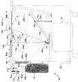
図2には、フレーム62内にPC20を含み、コンピュータの光入力およびビデオ表示デバイスの両方として使用される対話型表示テーブル60の実施例が示されている。対話型表示テーブルのこの切り欠き図では、テキストおよびグラフィック画像を表示するために使用される光線は、一般的に、点線を使用して示され、対話型表示テーブルの表示面64aに載っている、または真上にある物体を感知するために使用される赤外線(IR)光は、破線を使用して示されている。表示面64aは、対話型表示テーブルの上面64内にセットされる。テーブル面の周辺は、表示面64a上に表示されているグラフィック画像または仮想環境を対話形式で操作するために使用することができる物体を含む、ユーザの腕またはその他の物体を支えるために使用される。Interactive Surface Example FIG. 2 shows an example of an interactive display table 60 that includes a
IR光源66は、複数のIR発光ダイオード(LED)を備えるのが好ましく、フレーム62の内側に取り付けられる。IR光源66により出力されるIR光は、破線78a、78b、および78cにより示されるように、上向きに、表示面64aの下側に当てられる。IR光源66から出たIR光は、光拡散特性を有するベラムまたは他の好適な半透明材料のシートを含む、テーブルの半透明層64bを通過した後、表示面の上または近いところにある物体から反射される。図にはIR光源66が1つしか示されていないが、そのような複数のIR光源は、フレーム62の内側の周りの間隔を空けた位置に取り付けて、表示面64aを均等に照らすようにできることは理解されるであろう。IR光源により出力される赤外線は、
・破線78aにより示されているように、物体を照らさずに、テーブル面を抜けるか、
・破線78bにより示されているように、テーブル面上の物体を照らすか、
・破線78cにより示されているように、テーブル面から上に短い距離のところにあり、テーブル面と接触していない物体を照らすことができる。The IR
As indicated by the
Illuminate an object on the table surface, as indicated by dashed
As shown by the
表示面64aの上にある物体は、表示面の上に載る「タッチ」物体76aおよび表示面に近いが実際には接触していない「ホバー」物体76bを含む。半透明層64bを表示面の下に使用し、表示面を通過するIR光を拡散させた結果、物体が表示面64aに近づくにつれ、物体により反射されるIR光の量は、物体が実際に表示面と接触した場合に得られる最大レベルまで増大する。 Objects on the
デジタルビデオカメラ68は、表示面64aの下のフレーム62に取り付けられ、表示面64aの上の方に配置されたタッチ物体またはホバー物体から反射されるIR光を受信するのに適切な位置にある。デジタルビデオカメラ68は、IR光のみを透過し、点線84aに沿って表示面64a内を伝わる周辺可視光線をブロッキングするIRパスフィルタ86aを装備している。IR光源66とデジタルビデオカメラとの間に邪魔板79を配置し、IR光源から直接放射されたIR光がデジタルビデオカメラに入らないようにしたが、なぜかというと、このデジタルビデオカメラは、表示面64aから上に短い距離のところにある、または表示面64aに接触する物体から反射されたIR光にのみ反応(応答)し、表示面に載っている、またはその上の方にある物体から反射されたIR光の像に対応する出力信号を発生しなければならないからである。デジタルビデオカメラ68は、さらに、上から表示面64aを通り、対話型表示装置の内側に入る周辺光(例えば、点線84aにより示されている経路に沿っても伝わる周囲IR光)に含まれるIR光にも反応することは理解されるであろう。 The
テーブル面にある、またはその上の方にある物体から反射されたIR光は、
・反射して戻り、破線80aおよび80bにより示されているように、半透明層64bを通り、IRパスフィルタ86aを通り、デジタルビデオカメラ68のレンズ内に入るか、または
・破線80cに示されているように、デジタルビデオカメラ68のレンズに入ることなく、対話型表示装置内の他の内面により反射または吸収される可能性がある。IR light reflected from objects on or above the table surface is
Reflected back and through the
半透明層64bは、入射IR光と反射IR光の両方を拡散する。したがって、上で説明したように、表示面64aに近い「ホバー」物体ほど、表示面から遠い同じ反射率の物体と比べてより多くのIR光を反射して、デジタルビデオカメラ68に返す。デジタルビデオカメラ68は、撮像フィールド内の「タッチ」および「ホバー」物体から反射されたIR光を検知し、それぞれのそのような物体の位置、および任意選択により、物体のサイズ、配向、および形状を決定する処理のため、PC20に入力された反射IR光の像に対応するデジタル信号を出力する。物体の一部(ユーザの指など)が表示面に接触している間に、物体の他の部分(ユーザの前腕など)がテーブルの上にあってよいことに留意されたい。さらに、物体は、その物体またはその物体が一員である関連する物体のクラスに特有のその物体に固有の底面についているIR光反射パターンまたはコード化された識別子(例えば、バーコード)を含むことができる。したがって、デジタルビデオカメラ68からの撮像信号は、さらに、本発明により、反射パターンから反射されたIR光に基づいて、それぞれのそのような固有の物体を検出するだけでなく、その配向を決定するのにも使用することができる。この機能を実行するために実装される論理的ステップについて以下で説明する。 The
PC20は、図2に示されているように対話型表示テーブル60と一体であるか、またはその代わりに、図3の実施形態に示されているように、対話型表示テーブルに対し外付けとすることもできる。図3では、対話型表示テーブル60’は、データケーブル63を通じて外部のPC20(上述のように、オプションのモニタ47を含む)に接続されている。さらに、この図に示されているように、1組の直交軸XおよびYが、表示面64aに関連付けられており、また「0」で示される原点も関連付けられている。個別には示されていないが、それぞれの直交軸に沿う複数の座標位置を使用して、表示面64a上の位置を指定できることは理解されるであろう。 The
対話型表示テーブルが外部のPC20に接続されるか(図3のように)、またはセットトップボックス、テレビゲーム機、ラップトップコンピュータ、またはメディアコンピュータ(図に示されていない)などの他の種類の外部コンピューティングデバイスに接続されている場合、対話型表示テーブルは入力/出力デバイスを備える。対話型表示テーブルに送られる電力は、従来の交流(AC)電源(図に示されていない)に結合されている電源リード61を通じて供給される。対話型表示テーブル60’に接続されるデータケーブル63は、PC20上のUSB2.0ポート、Institute of Electrical and Electronics Engineers(IEEE)1394(またはファイヤワイヤ)ポート、またはEthernet(登録商標)ポートに結合することができる。また、無線接続の速度が向上し続けると、対話型表示テーブルも、そのような高速無線接続、または他の何らかの適切な有線または無線データ通信リンクを介して、PC20などのコンピューティングデバイスに接続されることもありうると考えられる。対話型表示装置の一体部分として内蔵されるか、または外付けされるかに関係なく、PC20は、デジタルビデオカメラ68からのデジタル画像を処理するアルゴリズムを実行し、よい所をひき立てて対話型表示テーブル60のより直観的なユーザインターフェイス機能を使用するように設計されたソフトウェアアプリケーションを実行し、さらに、そのような機能を利用するように特に設計されていないが、それでも、対話型表示テーブルの入力および出力機能を適切に使用できる他のソフトウェアアプリケーションをも実行する。 The interactive display table is connected to an external PC 20 (as in FIG. 3) or other type such as a set top box, video game machine, laptop computer, or media computer (not shown) The interactive display table comprises input / output devices when connected to external computing devices. The power sent to the interactive display table is supplied through a
対話型表示テーブル(つまり、上述のいずれかの実施形態)の重要で強力な特徴は、ゲームまたはその他のソフトウェアアプリケーションのためのグラフィック画像または仮想環境を表示し、グラフィック画像または仮想環境の間の対話操作を表示面64a上に表示できるようにし、物体76aなどの表示面の上に載っている物体、または物体76bなどの、その真上でホバリングしている物体を識別する機能である。 An important and powerful feature of the interactive display table (ie, any of the embodiments described above) is the display of graphic images or virtual environments for games or other software applications, and interaction between the graphic images or virtual environments. This is a function that enables an operation to be displayed on the
ここでもまた、図2を参照すると、対話型表示テーブル60は、グラフィック画像、仮想環境、またはテキスト情報を表示面64a上に表示するために使用されるビデオプロジェクタ70を備えている。ビデオプロジェクタは、解像度が少なくとも640×480ピクセルの液晶表示装置(LCD)またはデジタルライトプロセッサ(DLP)タイプであるのが好ましい。IRカットフィルタ86bは、ビデオプロジェクタ70のプロジェクタレンズの前面に取り付けられ、これにより、ビデオプロジェクタにより放射されたIR光が対話型表示テーブルの内部に入ってIR光が表示面64aに載っている、またはその上にある物体から反射されたIR光と干渉するのを防止する。第1の鏡組立部品72aは、投射光が第2の鏡組立品72b上に入射するように、点線82aに沿ってプロジェクタレンズから伝わる投射光をフレーム62内の透明開口部90aに通す。第2の鏡組立品72bは、投射像が見えるように、また表示のため表示面64a上に焦点が合うように、プロジェクタレンズの焦点のところにある半透明層64b上に投射光を反射する。 Again, referring to FIG. 2, the interactive display table 60 includes a
表示面に投射された像が表示面と必ず揃うように第1および第2の鏡組立品の角度を調整するため、位置合わせデバイス74aおよび74bが用意され、ネジ棒および回転可能調整ナット74cを含む。投射像を所望の方向に向ける他に、これら2つの鏡組立品を使用することで、プロジェクタ70と半透明層64bとの間の経路を長くできるため、焦点距離の長い(したがって低コストの)プロジェクタレンズをプロジェクタとともに使用することができる。 In order to adjust the angles of the first and second mirror assemblies so that the image projected on the display surface is always aligned with the display surface,
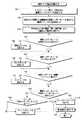
物体のコード認識
図4には、コード化された物体の二次元識別子コードを認識するための論理全体を例示する流れ図が示されている。ステップ100で、ゲームなどのアプリケーションプログラムでは、そのアプリケーション側でテーブル上にある物体に付いていることを検知することを期待する種類のコードを指定する。本発明で使用可能なコードの種類には、円形、リニア、マトリクス、可変ビット長マトリクス、多層マトリクス、白黒(バイナリ)、およびグレースケールがある。コードの種類を指定する方法としては、コードパターンの特性のロード、しきい値の設定、および/またはパターン認識に対するテンプレートの有効化が考えられる。テンプレートの有効化は、さらに、物体認識を容易にするテンプレートのいくつかの回転バージョンを生成することをも含むことができる。Object Code Recognition FIG. 4 shows a flow diagram illustrating the overall logic for recognizing a coded object two-dimensional identifier code. In
図4の残りの論理回路は、現在実行中のソフトウェアアプリケーションと通信する画像処理モジュールにより実行されるのが好ましい。このようにして、ソフトウェアアプリケーションは、標準的な方法により画像処理モジュールとインターフェイスすることができる。以下で詳しく説明するが、画像処理モジュールは、形状、ピクセル強度、コードタイプ、および対応するコード値を通じて物体を検出することに関係するさまざまな機能を実行する。例としては、物体がテーブル上に、任意の向きで出現できる場合にコード化された物体を見つけることを試みるテンプレート照合またはしきい値設定がある。 The remaining logic of FIG. 4 is preferably implemented by an image processing module that communicates with the currently executing software application. In this way, the software application can interface with the image processing module by standard methods. As described in detail below, the image processing module performs various functions related to detecting an object through shape, pixel intensity, code type, and corresponding code value. Examples include template matching or threshold setting that attempts to find a coded object when the object can appear on the table in any orientation.
ステップ102で、画像処理モジュールは、表示面上またはその付近にある1つまたは複数の物体から、テーブルの表示面から届いた反射されたIR光に対する応答としてIRビデオカメラにより出力される現在の入力像の2値画像内の接続コンポーネントを検出する。IR視覚システムのこの実施例では、接続コンポーネントは2値画像内の1組の隣接する「オン」ピクセルを含む。これらのピクセルは、IRビデオカメラに向かって反射IR光が戻るIR反射材料を含む二次元識別子コードの一部分を含む。接続コンポーネントは、対話型テーブル上に置かれている物体に付けられている識別子コード全体、またはその識別子付号のコード部分から分離されているサブコンポーネントに対応することができる。後述のいくつかの場合には、別々のサブコンポーネントが、識別子コードの位置および配向を決定するのを補助する手掛かりコンポーネントとして機能する。他の場合には、識別子コード全体がそれ専用の手掛かりコンポーネントとして使用され、それにより、識別子コードの位置および配向を特定する。2値画像は、正規化された入力画像のどのピクセルが所定の2値化しきい値を超えるかを判別することにより形成される。接続コンポーネント検出は、B.K.P.Horn(「ロボット視覚」を参照)により説明されているアルゴリズムなどの標準アルゴリズムを使用して実行される。 In
ステップ104では、画像処理モジュールは、接続コンポーネントを楕円として表し、楕円の長軸および短軸の中心および長さを計算する。その後、画像処理モジュールは、接続コンポーネントのピクセルに対する平均値および共分散値を求め、楕円軸に沿ってのピクセルの統計的平均および共分散に基づき、対話型表示テーブルの座標に関して接続コンポーネントの位置および配向を決定する。この手法の詳細については、例えば、非特許文献2を参照のこと。 In
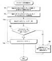
接続コンポーネントの位置および配向を決定した後、画像処理モジュールは1つまたは複数の任意選択の決定ステップを実行することによりコードのタイプおよび値を容易に決定できる。一実施形態では、任意選択の決定ステップ106、110、114、118、および120は、使用されず、プロセスは順次、ステップ104からコード決定ステップ108、112、116、122、124を通り、ステップ126へと流れ、そこでコード決定の結果の順位付けを行い、統計解析に基づいて最も近いコードタイプを選択する。第2の実施形態では、これらの任意選択の決定ステップは、実行されるべきコード決定ステップを選択するために使用される。例えば、任意選択の決定ステップ106は、コード決定ステップ108が実行されるべきかどうかを示す。したがって、この実施形態は、コード検出に必要な計算量を減らすフィルタとして機能する。 After determining the position and orientation of the connecting component, the image processing module can easily determine the type and value of the code by performing one or more optional determination steps. In one embodiment, the optional decision steps 106, 110, 114, 118, and 120 are not used, and the process proceeds sequentially from
コードタイプがうっかり捨てられないようにするため、上記の手法の組み合わせを使用することができる。組み合わせられた手法では、複数の任意選択の決定ステップを使用して、「信頼度」係数を決定されるそれぞれのコードタイプに割り当てることができる。例えば、画像処理システムでは、決定ステップ106での決定に従い、指定された半径内に収まる接続コンポーネントの統計解析に基づいて信頼度係数を割り当てることができる。同様に、画像処理モジュールでは、同じ接続コンポーネントが決定ステップ110での決定に従い指定された正方形領域内に収まる場合に他の信頼度係数を割り当てることができる。他の信頼度係数は、さらに、接続コンポーネントの短軸と指定された長さとが等しいかどうか(決定ステップ114の場合)、接続コンポーネントと指定された形状との一致(決定ステップ118の場合)、または接続コンポーネントへのビットの近さ(決定ステップ120の場合)について決定することもできる。一般に、信頼度係数は、コードタイプ毎に決定することができ、現在の検出されたコンポーネントに最も当てはまるコードタイプを決定する際にこの信頼度係数を使用できる。例えば、信頼度係数は、ピクセルがどれだけよく「読み取られるか」、つまり、白黒強度レベルにどれだけくっきりと分けられるか、およびさらにピクセル値が有効なコードのコードブックからの有効なビットコードのうちの1つとしてどれだけよく「読み取られるか」ということからも決定することができる。また、信頼度レベルは、最大および最小ピクセル強度レベルが少なくともある程度の所定の値だけ異なるかどうかにより決定することができるが、それは、それらの強度の差の値が小さすぎると、ピクセルはノイズとなる可能性があるからである。 A combination of the above techniques can be used to ensure that code types are not inadvertently discarded. In a combined approach, a plurality of optional decision steps can be used to assign a “confidence” factor to each code type to be determined. For example, the image processing system can assign a reliability factor based on a statistical analysis of connected components that fall within a specified radius, as determined in
例として、図4では、接続コンポーネントが少なくとも最小基準条件を満たすそれぞれのコードタイプに対するコード値を決定しながら、それぞれのコードタイプに対する最小基準条件を満たさないコードタイプを除去するために使用される第1と第2の実施形態の組み合わせを示している。これらの任意選択の決定ステップは、一致する可能性のあるコードタイプについて接続コンポーネントを最初にふるいにかけるため単独で、または組み合わせて実行することができる。接続コンポーネントが一致する可能性のあるコードタイプについて、画像処理モジュールでは、それぞれの一致する可能性のあるコードタイプから接続コンポーネントの分散を決定するのが好ましい。その後、画像処理モジュールは、最良適合により決定を順位付けして、最も一致度の高いコードタイプおよび対応するコード値を、物体に付けられたコードとして選択する。 As an example, in FIG. 4, the connected component is used to remove code types that do not meet the minimum criteria for each code type while determining a code value for each code type that satisfies at least the minimum criteria. The combination of 1 and 2nd embodiment is shown. These optional decision steps can be performed alone or in combination to initially screen the connected components for possible code types. For code types where the connected components may match, the image processing module preferably determines the distribution of the connected components from each possible code type. The image processing module then ranks the decisions by best fit and selects the code type with the highest match and the corresponding code value as the code attached to the object.
上で示されているように、任意選択の決定ステップ106で、画像処理モジュールは、特定の半径または放射状マスク内に収まるかどうかについて接続コンポーネントをテストする。接続コンポーネント軸の長さおよび/またはピクセル値の総和が定義済み範囲内にある(つまり、接続コンポーネントが放射状マスクの範囲内に収まる)場合、画像処理モジュールはステップ108に進み、放射状コードを決定する。放射状コードの決定の詳細は、図5および6に関して以下で説明される。放射状コードを決定した後、または接続コンポーネントが定義済み半径または放射状マスクの範囲内に収まらない場合、処理は任意選択の決定ステップ110に進む。 As indicated above, in an
任意選択の決定ステップ110では、画像処理モジュールは、ダイの寸法に対応する指定正方形領域内に収まるかどうかについて接続コンポーネントをテストする。接続コンポーネントが回転された白色の正方形テンプレートと一致するか、または主軸および副軸が等しい長さであり、定義済みダイ寸法に対応する(つまり、接続コンポーネントがダイ寸法の範囲内に収まる)場合、画像処理モジュールはステップ112に進み、ダイのスポットパターンを決定する。ダイのスポットパターンの決定の詳細は、図7および8に関して以下で説明される。ダイのスポットパターンを決定した後、または接続コンポーネントが知られているダイの寸法に対応する指定された正方形領域の範囲内に収まらない場合、処理は任意選択の決定ステップ114に進む。 In
任意選択の決定ステップ114では、画像処理モジュールは、リニアコード高さに対応する所定の長さと等しいかどうかについて接続コンポーネントをテストする。接続コンポーネントの短軸の長さが所定の長さに等しい(つまり、接続コンポーネントの2番目の軸がリニアコード高さに等しい)場合、画像処理モジュールはステップ116に進み、そのリニアコードを決定する。リニアコードの決定の詳細は、図9および10に関して以下で説明される。リニアコードを決定した後、または接続コンポーネントの副軸が所定の長さに等しくない場合、処理は任意選択の決定ステップ118に進む。 In an
任意選択の決定ステップ118では、画像処理モジュールは、所定の形状または手掛かりコンポーネントと一致するかどうかについて接続コンポーネントをテストする。接続コンポーネントが1つの知られている寸法を持つ直線の形状でない(つまり、接続コンポーネントは手掛かりコンポーネントと一致していない)場合、画像処理モジュールはステップ126に進み、そのような直線の形状である場合、画像処理モジュールは任意選択の決定ステップ120に進む。 In an
任意選択の決定ステップ120で、画像処理モジュールは、近隣コードビットについて接続コンポーネントをテストする。接続コンポーネントの所定の距離および配向の範囲内に非連結ビットがある(つまり、接続コンポーネントが近隣コードビットを持つ)場合、画像処理モジュールはステップ122に進み、マトリクスコードを決定する。マトリクスコードの決定の詳細は、図11および12に関して以下で説明される。マトリクスコードを決定した後、または接続コンポーネントの所定の距離および配向の範囲内に非連結ビットがない(つまり、接続コンポーネントが近隣コードビットを持たない)場合、画像処理モジュールはステップ124に進み、グレースケールコードを決定する。グレースケールコードの決定の詳細は、図13、14、および15に関して以下で説明される(ステップ122からステップ124への論理の流れは第1の実施形態の順次的な論理の流れを示す)。 In an
ステップ126で、画像処理モジュールは、(複数の)コード決定の結果を順位付けし、その後、統計解析を実行して、接続コンポーネントが適合する可能性が最も高いコードタイプを選択する。接続コンポーネントが、コードとして検出されない場合、画像処理モジュールは、その接続コンポーネントを識別子が付けられていない、ユーザの指または非コード化物体などの他のタイプの物体であると評価することができる。 At
放射状コード認識
図5は、丸い物体、つまり丸い「フットプリント」を持つ物体に識別子を付ける際に特に有用な放射状コード130の実施例を示している。放射状コード130は、暗い「開始ビット」134を持つ光反射内部円形領域132を含む。開始ビット134は、コード化領域の中心から定義済みの第1の半径のところに配置されるのが好ましく、キーストーン、パイスライスの形状、または開始ビットを簡単に特定できるその他の形状を取ることができる。光反射内部円形領域内の開始ビットは、コード値を決定できる開始基準点を定める。開始ビットは、光反射内部円形領域に関して、さらに、コードが付けられる物体の配向を定義する。Radial Code Recognition FIG. 5 shows an example of a
放射状コード130は、さらに、明るいキーストーン形状と暗いキーストーン形状の「データビット」を伴う外側の均等に分割された同心状円環136を含む。円環136は、第1の半径よりも大きい中心からの第2の半径のところに配置される。破線は、この図の中にのみ含まれ、データビットの配置をより明確に示すことに留意されたい。しかし、実際の放射状コードは、そのような線を含まず、光反射領域全体が単一の接続コンポーネントを含む。この場合、識別子コード全体がそれ独自の手掛かりコンポーネントとして機能する。外側の均等に分割された同心状円環は、コードの値を、明るいキーストーン形状と暗いキーストーン形状のビットの一連の並びとして含む。コード値は、定義済みの時計回り(または代わりに、好ましい反時計回り)の方向で開始ビットを配置することから始めて、読み取られる。 The
暗い背景138は、放射状コードが接続コンポーネントとして簡単に検出できるように、放射状コード130を囲む。暗い背景では、「ノイズ」ピクセルが接続コンポーネントの一部としてみなされるリスクを極力小さくする。 A
図6は、放射状コードを処理するため画像処理モジュールにより実行される論理的ステップを例示する流れ図である。ステップ140で、画像処理モジュールは、円形領域の中心から定義済み半径のところで開始ビットを探索する。探索領域は、データビットの半径以内に配置される。一般に、画像処理モジュールでは、定義済み固定しきい値を使用して、任意のビットの値を決定することができる。しかし、信頼性を高めるために、画像処理モジュールは、しきい値をコードパターンの最小ピクセル値と最大ピクセル値との平均値として計算するのが好ましい。上述のように、最小ピクセル値と最大ピクセル値との差が小さすぎるのは、ノイズを復号化しようとすることが原因である可能性がある。 FIG. 6 is a flow diagram illustrating the logical steps performed by the image processing module to process the radial code. In
決定ステップ142で、画像処理モジュールは、定義済み半径のところで開始ビットが見つかったかどうかを判定する。開始ビットが見つからない場合、放射状コード決定のプロセスは終了する。しかし、開始ビットが見つかった場合、画像処理モジュールはステップ144に進み、定義済みの時計回り(または反時計回り)の方向に円形領域の中心から定義済み半径のところでデータビットを読み込む。これらのビットは、入力画像からの変形されたテーブル座標に関して知られている半径方向の幅を持つ。 In
任意選択の決定ステップ146で、有効な放射状コードかどうかをテストする。放射状コードの有効性をテストするために、画像処理モジュールは、検出されたビットが可能な有効なコード値からなるテーブル内に存在するコード値を表すことを検証することを試みることができる。その代わりに、画像処理モジュールは、接続コンポーネントを有効な放射状コードのテンプレートと比較することができる。このパターンマッチング手法を、図8に関して詳述する。検出されたコードが有効なコードでない場合、放射状コード決定のプロセスは終了する。検出されたコードが有効な場合、または任意選択の有効性検査が実行されない場合、画像処理モジュールは、ステップ148に進み、テーブルルックアップまたは他のそのような方法を使用してコード内で検出されたビットから物体IDを決定する。 An
ダイマトリクスコード認識
図7は、ダイの面などの正方形の物体を認識する際に使用されるマトリクスコード150の実施例を示している。マトリクスコード150は、1から6個のデータビット154(ダイスポット)が3×3のグリッド158内に6つの所定のパターンで配列されている接続コンポーネントの正方形領域152(白色で示されている)を含む。破線は、データビットを例示するために図に含まれているだけであり、実際のダイマトリクスコードは線を含まないことに留意されたい。Die Matrix Code Recognition FIG. 7 shows an example of a
ダイのピクセルは、正方形領域内の3×3グリッドから読み取られる。この後、3×3グリッドパターンは、6つの許容可能なダイフェースパターンのそれぞれと比較され、「2」、「3」、または「6」のスポットダイフェースの場合は、さらに、90度回転されたバージョンのダイフェースパターンとも比較される。その代わりに、任意のサイズおよび関連するダイフェースビットパターンのグリッドを読み取ることもできる。表示面に面しているダイフェースが識別された後、反対側のダイフェースは常に定義済みの関係を持つ、つまり、知られているダイフェースに向かい合うダイフェースは7と知られているダイフェースとの差に等しい数のスポットを持つため上を向いているダイフェースが知られる。 The die pixels are read from a 3 × 3 grid in a square area. After this, the 3 × 3 grid pattern is compared with each of the six acceptable die face patterns, and for “2”, “3”, or “6” spot die faces, it is further rotated 90 degrees. It is also compared with different versions of the die face pattern. Alternatively, a grid of arbitrary sizes and associated die face bit patterns can be read. After the die face facing the display surface is identified, the opposite die face always has a predefined relationship, ie, the die face facing the known die face is known as 7 A die face facing upward is known because it has a number of spots equal to the difference between and.
暗い背景156は、マトリクスコードが接続コンポーネントとして簡単に検出できるように、マトリクスコード150を囲む。暗い背景では、「ノイズ」ピクセルが接続コンポーネントの一部としてみなされるリスクを極力小さくする。 A
図8は、ダイマトリクスコードを決定するため画像処理モジュールにより実行される論理的ステップを例示する流れ図である。ステップ160で、画像処理モジュールは、白色の正方形テンプレートを90度までの所定の角度だけ回転し、テンプレートと接続コンポーネントとの照合を行うことにより正方形の接続コンポーネントの配向を決定する。その後、画像処理モジュールは、ステップ162に進んで、3×3グリッド内から接続コンポーネントの2値化画像のピクセルパターンを読み取る。 FIG. 8 is a flow diagram illustrating the logical steps performed by the image processing module to determine the die matrix code. In
ステップ164aでは、それぞれの知られているダイフェースパターン(および「2」、「3」、または「6」個のスポットがあるダイフェースの場合には、90度回転させたバージョンのダイフェースパターン)を繰り返し調べるプロセスを開始する。決定ステップ166で、接続コンポーネントから読み取られたピクセルパターンと知られているダイフェースパターンとを比較する。ピクセルパターンが知られているダイフェースパターンと一致した場合、画像処理モジュールはステップ168に進み、ダイの上面の値を決定する。上述のように、ダイ上の対面の合計は7に等しく、上面の値は7引く検出パターン内のスポット数に等しい。上面の値を決定した後、画像処理モジュールは終了する。ただし、知られているダイフェースパターンが接続コンポーネントのピクセルパターンと一致しない場合、反復プロセスはステップ164bで終了する。 In step 164a, each known die face pattern (and the version of the die face pattern rotated 90 degrees for a die face with “2,” “3,” or “6” spots). Start the process of checking repeatedly. In a
リニアコード認識
図9は、物体の認識で使用されるリニアコード170の実施例を示す。リニアコード172は、2つの明るい平行なバー174aと174b、明るい開始ビット176、暗い停止ビット178、および複数の明るいまたは暗いコードビット180を含む。「明るい」および「暗い」という用語は、物体または物体自体の材料上のコード化パターンを作成するために適用される材料のIR反射率を意味することは明白であろう。明るいビットは、IR光の良好な反射器である識別子の一部に対応し、暗いビットまたは領域は、識別子の一部またはIR光を吸収する、またはあまりよく反射しない物体の囲む部分に対応する。これらの用語は、表示面の像は電子的に容易に反転できるため、いくぶん恣意的である。Linear Code Recognition FIG. 9 shows an example of a
暗い背景182は、リニアコードが接続コンポーネントとして簡単に検出できるように、リニアコードを囲む。暗い背景では、「ノイズ」ピクセルが接続コンポーネントの一部としてみなされるリスクを極力小さくする。ここでもまた、データビットを線引きする線は、データビットを例示するだけのために図に含まれていることに留意されたい。実際のリニアコードは、通常、識別可能な線を含まない。 A
リニアコードは、接続コンポーネントであり、主軸または長軸に関して対称的である。接続コンポーネントプロセスから計算されるような配向は、コードを表示する物体の真の向きから180度ずれることがある。開始ビットおよび停止ビットの位置を調べることにより、復号化アルゴリズムにより、配向の訂正を行うことができる。リニアコード内のビットの個数は可変である。ビットのサイズ(例えば、幅)が与えられると、リニアコード内のビットの個数は、明るい平行なバーの長さから直接決定することができる。リニアコードの実施例172aから172hは、3ビットコードの8つすべてのインスタンスを示している。 A linear cord is a connecting component and is symmetric about a major axis or a major axis. The orientation as calculated from the connected component process may be 180 degrees off the true orientation of the object displaying the code. By examining the position of the start bit and stop bit, the orientation can be corrected by the decoding algorithm. The number of bits in the linear code is variable. Given the size of the bits (eg, width), the number of bits in the linear code can be determined directly from the length of the bright parallel bars.
図10は、リニアコードを決定するため画像処理モジュールにより実行される論理的ステップの論理的ステップを例示する流れ図である。ステップ190で、画像処理モジュールは、主軸(長軸)の角から開始し、接続コンポーネントの主軸に垂直なそれぞれの線の中のピクセル値を総和することにより、接続コンポーネントの終了辺を特定する。リニアコンポーネント終端は、総和が0か、または所定の低いしきい値以下である場合に確認される。開始ビットの終了では、終了ビットの終了よりも大きな総和を持つことになる。決定ステップ192で、画像処理モジュールは、開始ビットの存在についてテストする。開始ビットが見つからない場合、リニアコードを決定するプロセスは終了し、見つかれば、プロセスはステップ194に続き、ステップ190で見つかった接続コンポーネントの終わりからコードの長さを決定する。 FIG. 10 is a flow diagram illustrating the logical steps of the logical steps performed by the image processing module to determine the linear code. In
任意選択の決定ステップ196で、画像処理モジュールは、有効なコード長についてテストする。物体が検出されるソフトウェアアプリケーションに基づき、コードの長さが予期した通りでない場合、リニアコードを決定するプロセスは終了する。ソフトウェアアプリケーションにより、コードの長さが予期した通りの場合、または有効なコード長についてテストする任意選択の決定が実行されない場合、プロセスはステップ198に進み、コード内のビットの個数を決定する。コード内のビットの個数は、以下の式で計算される。
コードビット=(接続コンポーネント長/ビット幅)−2In an
Code bit = (connection component length / bit width) -2
プロセスはステップ200に進み、長軸または主軸に沿ってそれぞれのコードビットの値を決定する。コードビット値は、
・コードビットの中心にあるピクセルの値に基づくか、または
・コードビットの領域内のすべての値の総和の平均値と所定のしきい値とを比較し、平均値が所定のしきい値よりも大きい場合には、コードビット値は「1」であるとすることにより、または
・パターンマッチングによるか、または
・他の何らかの司法使用することにより決定することが可能である。The process proceeds to step 200 to determine the value of each code bit along the major or major axis. The code bit value is
-Based on the value of the pixel at the center of the code bit, or-Compare the average value of the sum of all values in the area of the code bit with a predetermined threshold value, and the average value is less than the predetermined threshold value. Can be determined by assuming that the code bit value is “1”, or by pattern matching or by using some other judicial use.
プロセスはステップ202に進み、テーブルルックアップまたは他のそのような方法を介してコードビットの値から物体IDを決定する。 The process proceeds to step 202 to determine the object ID from the value of the code bit via a table lookup or other such method.
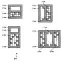
可変ビット長マトリクスコード認識
図11は、物体の認識で使用される可変ビット長マトリクスコード210の実施例を示す。可変ビット長マトリクスコード212は、明るい矩形の接続「手掛かり」コンポーネント214を含む。手掛かりコンポーネントの副軸または短軸は固定長であるが、主軸または長軸は、任意の長さ(短軸よりも長い)でよい。可変ビット長マトリクスコードの配向の推定は、リニアコードとほとんど同じようにして導かれる。手掛かりコンポーネントの配向は、最大180度の回転まで正しく、これは、さらに、ビットフィールドが配置されている手掛かりコンポーネントの辺を決定することにより訂正することができる。手掛かりコンポーネントの形状により、対応する楕円形モデルの配向信頼性を高めることが好ましい。Variable Bit Length Matrix Code Recognition FIG. 11 shows an example of a variable bit
可変ビット長マトリクスコードは、さらに、マトリクスフィールド216も含み、これは、手掛かりコンポーネントの一辺または両辺上の手掛かりコンポーネントの主軸から一定距離のところに配置される。データビットを線引きする線は、データビットを例示するだけのために図に含まれているのであり、実際のダイマトリクスコードは見える線を含まないことに留意されたい。マトリクスフィールドの幅は、手掛かりコンポーネントの主軸の長さに等しい。マトリクスフィールドは、1つまたは複数のデータビット行を含む。マトリクスフィールドの各行は、少なくとも1つの明るい、または白色ビットを含み、このため、復号化アルゴリズムでは、1行内に白色ビットが見つからなくなるまで、手掛かりコンポーネントから外に向かって連続する行を読み取ることによりビットの行数を決定することができる。その代わりに、マトリクスフィールド内の行の数は、マトリクスフィールドの第1の行の中にコード化することができる。手がかりコンポーネントの可変長の主軸とともに、可変個数の行を使用することにより、コードはさまざまな物体サイズに合わせて適切な形状を取るようにできる。マトリクスフィールドは、1つまたは複数のチェックサムビットを含むことができるので、画像分析によりビットシーケンスが復号化された後、復号化の誤りを検出することができる。チェックサムビットは、さらに、復号化プロセスが手掛かりコンポーネントの正しい辺からビットシーケンスを読み取ったかどうかについて、その問題を判別する他の手順がない場合に、それを決定するために使用することができる。そのようなアルゴリズムは、単に、手掛かりコンポーネントの両辺から復号化を試みて、有効なシーケンスを正しいビットパターンとして使用するだけである。その代わりに、手掛かりコンポーネントの形状は、コードが配置されているマトリクスの辺を示すことができる。 The variable bit length matrix code further includes a matrix field 216, which is located at a distance from the main axis of the cue component on one or both sides of the cue component. Note that the lines that delineate the data bits are included in the figure only to illustrate the data bits, and the actual die matrix code does not include visible lines. The width of the matrix field is equal to the length of the main axis of the clue component. The matrix field includes one or more data bit rows. Each row of the matrix field contains at least one bright or white bit, so the decoding algorithm reads the bit by reading successive rows out of the cue component until no white bit is found in one row. The number of rows can be determined. Instead, the number of rows in the matrix field can be encoded in the first row of the matrix field. By using a variable number of rows, along with the variable length principal axis of the cue component, the code can be shaped appropriately for different object sizes. Since the matrix field can include one or more checksum bits, decoding errors can be detected after the bit sequence is decoded by image analysis. The checksum bit can also be used to determine if there is no other procedure to determine the problem as to whether the decoding process has read the bit sequence from the correct side of the clue component. Such an algorithm simply tries to decode from both sides of the clue component and uses the valid sequence as the correct bit pattern. Instead, the shape of the clue component can indicate the side of the matrix where the code is located.
可変ビット長マトリクスコードは、暗い背景218により囲まれる。暗い背景により、手掛かりコンポーネントを接続コンポーネントとして容易に検出することができ、「ノイズ」ピクセルを手掛かりコンポーネントおよびマトリクスフィールドの一部とみなす危険性を最小限に抑えられる。 The variable bit length matrix code is surrounded by a dark background 218. The dark background allows the cue component to be easily detected as a connected component, minimizing the risk of considering “noise” pixels as part of the cue component and matrix field.
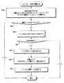
図12は、可変ビット長マトリクスコードを決定するため画像処理モジュールにより実行される論理的ステップを例示する流れ図である。ステップ230で、画像処理モジュールは、手掛かりコンポーネントの長さを決定する。画像処理モジュールは、手掛かりコンポーネントを楕円として表し、楕円の長軸および短軸の中心および長さを計算する。次に、画像処理モジュールは、楕円形の軸の統計学的平均および共分散から、テーブル座標に関する手掛かりコンポーネントの位置および配向を決定する。 FIG. 12 is a flow diagram illustrating the logical steps performed by the image processing module to determine the variable bit length matrix code. In step 230, the image processing module determines the length of the clue component. The image processing module represents the clue component as an ellipse and calculates the center and length of the major and minor axes of the ellipse. The image processing module then determines the position and orientation of the clue component with respect to the table coordinates from the statistical mean and covariance of the elliptical axes.
処理はステップ232に進み、マトリクスフィールドの1行当たりのビット数を決定する。コードビットの幅は固定であり、知られているため、1行当たりのビット数はコードビットの知られている幅で除算された手掛かりコンポーネントの長さに等しい。 Processing proceeds to step 232 where the number of bits per row of the matrix field is determined. Since the code bit width is fixed and known, the number of bits per row is equal to the length of the cue component divided by the known width of the code bits.
好ましい任意選択のステップ234では、画像処理モジュールは、2値化画像の代わりに正規化された画像にアクセスして、さらに処理を容易にする。正規化された画像を2値化すると、ノイズピクセルが入り込むことが多いが、正規化された画像からビットを読み取ると、比較的信頼性の高いピクセル値が得られ、より小さなビットパターンを読み取ることができる。 In a preferred
ブロック236a内のプロセスは、手掛かりコンポーネントの一辺上の可変ビット長マトリクスコードの値を確認する。ステップ238aでは、手掛かりコンポーネントの一辺のマトリクスフィールドの各行を繰り返しアドレス指定するプロセスを開始する。マトリクスフィールドの各行は手掛かりコンポーネントから連続する所定のオフセット距離のところに配置されているため、コードビットの読み取りの反復は、離散ステップで実行される。ステップ240aで、プロセスはマトリクスフィールドの1行内のデータビットを読み取る。データビットの読み取りは、定義済みの固定しきい値または相対的しきい値を使用して実行されるのが好ましく、その場合、相対的しきい値は、最大ピクセル強度と最小ピクセル強度との差の関数として決定される。パターンマッチングは可能であるが、可変長の行と可変個の行を検出する自由度は制限される。 The process in
決定ステップ242aで、コードの終わりを示す、コードビットの不足がないかをテストする。その行にコードビットが含まれていない場合、反復プロセスは終了し、含まれている場合、プロセスはステップ244aに進み、行コードを格納しておいて後で処理する。反復プロセスはステップ246aに進む。
続いて、ブロック236b内の任意選択のプロセスは、手掛かりコンポーネントの対辺上の可変ビット長マトリクスコードの値を確認する。このステップは、アプリケーションプログラム側で可変ビット長マトリクスフィールドが手掛かりコンポーネントの両辺に含まれるべきと予期している場合、またはアプリケーションプログラムが手掛かりコンポーネントの両辺から読み取りを試み、アルゴリズムを使用し、チェックサムまたはその他の妥当性確認プロセスを使ってコードの妥当性を確認する場合に実行されるが、それは、マトリクスコードの配向が±180度で決定されるからである。 Subsequently, the optional process in
任意選択のステップ238bでは、手掛かりコンポーネントの対辺のマトリクスフィールドの各行を繰り返しアドレス指定するプロセスを開始する。これ以降、任意選択のステップ240b、242b、244b、および246bは、ステップ240a、242a、244a、および246aと同じ機能をそれぞれ実行するが、ただし、手掛かりコンポーネントの対辺上のビットに対してである。コード決定プロセスはステップ248に進み、そこで、ルックアップテーブルまたは他の適切な方法使用してステップ244で格納されているコードビットから物体IDを決定する。
グレースケールコードおよび任意形状コードの認識
図13は、物体の認識で使用されるグレースケールコード252の実施例を示す。グレースケールコードでは、複数のしきい値を使用して、白黒画像だけでなくグレースケール画像をも検出する。グレースケールコード252aは、接続「手掛かり」コンポーネント254aを含む。暗い背景252aは、グレースケールコードが接続コンポーネントとして簡単に検出できるように、グレースケールコードを囲む。暗い背景により、手掛かりコンポーネントを容易に検出することができ、「ノイズ」ピクセルを手掛かりコンポーネントの一部とみなす危険性を最小限に抑えられる。入力画像の2値化では、しきい値を、入力画像を白黒でレンダリングする所定のレベルに設定する。したがって、2値化された手掛かりコンポーネントは白色であり、そのため、手掛かりコンポーネントとして容易に識別可能である(灰色ビットは2値化画像内では白色である)。Grayscale Code and Arbitrary Shape Code Recognition FIG. 13 shows an example of a grayscale code 252 used in object recognition. The gray scale code uses a plurality of threshold values to detect not only a black and white image but also a gray scale image.
手掛かりコンポーネントが検出された場合、第2の所定のしきい値が正規化された画像に適用され、手掛かりコンポーネント内の灰色および白色のコードビットを現す。この所定の第2のしきい値は、さらに、上で説明したように決定される、相対的しきい値であってよい。したがって、2値化された手掛かりコンポーネント254a、254c、254e、および254gは対をなす片割れのグレースケールコンポーネント254b、254d、254f、および254hをそれぞれ含む。灰色および白色のデータビットは、手掛かりコンポーネントに関する定義済み位置に配置される。データビットを線引きする線は、データビットを例示するだけのために図に含まれていることに留意されたい。ただし、実際のグレースケールコードは、通常、そのような見える線を含まない。 If a cue component is detected, a second predetermined threshold is applied to the normalized image to reveal gray and white code bits in the cue component. This predetermined second threshold may also be a relative threshold determined as described above. Thus,
グレースケールコードに対する手掛かりコンポーネントは、手掛かりコンポーネント例254cおよび254gにより示されているように、矩形である必要はない。接続コンポーネントが認識された後、第2の所定のしきい値は、接続コンポーネント内のグレースケールコードビットを現すことができる。その代わりに、グレースケールコードでは、手掛かりコンポーネントを特定するためにパターン認識を使用することもできる。 The clue component for the grayscale code need not be rectangular, as shown by the clue component examples 254c and 254g. After the connection component is recognized, the second predetermined threshold can represent a grayscale code bit in the connection component. Alternatively, with grayscale code, pattern recognition can be used to identify clue components.
グレースケールコードの埋め込みの性質により、共通の中心を持つ2つの接続コンポーネントを使用することができる。接続コンポーネントのこのような配列は、偶然起こることは非常にあり得ず、容易に検出される。手掛かりコンポーネント例252eは、他の接続コンポーネント254e内に中心を置く接続コンポーネント255eを含む。グレースケールコードの配向は、手掛かりコンポーネント内のいくつかのコードビットが白色、灰色、またはその独自の組み合わせであると規定することにより定義することができる。例えば、グレースケールコンポーネント254bおよび254fの配向は、コーナービットの1つだけ除いて全部が灰色である必要がある場合に容易に確認される。254cおよび254gなどの非対称の手掛かりコンポーネントの形状は、グレースケールコードの配向を明確に示すことができる。グレースケールコードは、複数のチェックサムビットを含むことができるので、画像分析によりビットシーケンスが復号化された後、復号化の誤りを検出することができる。 Due to the embedding nature of the grayscale code, two connected components with a common center can be used. Such an arrangement of connecting components is very unlikely to happen by chance and is easily detected. The
図14は、物体、特に奇妙な形の物体を認識する際に使用される任意形状コード例260を示す。任意形状コード260は、接続「手掛かり」コンポーネント262、および1つまたは複数のデータビット264を含む。任意形状コードは、暗い背景268により囲まれる。暗い背景により、手掛かりコンポーネントデータビットを容易に検出することができ、「ノイズ」ピクセルをコードの一部とみなす危険性を最小限に抑えられる。任意形状コードのデータビットは、手掛かりコンポーネントに関する定義済み位置に置かれている。その代わりに、データビットを、それぞれのデータビットの位置が予め定義されるように前のデータビットに関する定義済み位置に置くこともできる。 FIG. 14 shows an example
任意形状コードは、さらに、1つまたは複数の空の領域266を含むこともできる。このような空の領域は、コードが付けられる物体の形状に内在することがある。空の領域は、データビットの配置に影響を及ぼす場合がある。例えば、データビット264bは、空の領域266によりデータビット264aから隔てられる。その代わりに、空の領域は、一定の力でつる巻きバネ304を押したときに、例えば、IR反射領域306を移動して表示面と接触させることによりコード内の1つまたは複数のビットの値を変化させるボタン302を含む物体などで、コードに影響を及ぼすことができるメカニズムに関連付けることができる。その代わりに、ボタンは、前述のコードのどれかで通常ビットの反射率を変えることもできる。 The arbitrary shape code may further include one or more
図15は、接続コンポーネントを特定した後にグレースケールまたは任意形状コードを決定するため画像処理モジュールにより実行される論理的ステップを例示する流れ図である。ステップ270で、画像処理モジュールは、灰色の陰影を含む現在の正規化された画像にアクセスする。ステップ272で、画像処理モジュールは、接続コンポーネント内の最小灰色強度を決定する。このステップでは、グレースケールまたは任意形状コードの暗い背景をグレースケールまたは任意形状コード内のコードから区別する。ステップ274は、画像処理モジュールで、以下の式で定義される第2のしきい値Tを設定することを示している。
T=(最大白色強度−最小灰色強度)/2FIG. 15 is a flow diagram illustrating the logical steps performed by the image processing module to determine grayscale or arbitrary shape codes after identifying connected components. At
T = (maximum white intensity−minimum gray intensity) / 2
このしきい値を正規化された画像に適用することにより、灰色ビットと白色ビットとを区別できる。ステップ270、272、および274は、任意形状コードのビットを読み取るうえで必要ではない。しかし、正規化された画像にアクセスすると、小さなビットも正確に読み取ることができる。 By applying this threshold to the normalized image, it is possible to distinguish between gray bits and white bits.
ステップ276で、画像処理モジュールは、予想されるビット位置の定義済みパターンにアクセスする。これらの定義済み位置は、手掛かりコンポーネント内のビットおよび/または手掛かりコンポーネントの外部の、ただしそれに関する定義済みビット位置に適用可能である。画像処理モジュールは、ステップ278において、接続コンポーネントの形状および配向に関してステップ276で事前に定義されているパターンでデータビットを読み取る。これらのデータビットは、第2のしきい値を使用して読み取られる。 At
任意選択の決定ステップ280で、画像処理モジュールは、有効なコード値についてテストする。コード値が有効でなければ、プロセスは終了し、有効であれば、プロセスはステップ282に進み、そこで、テーブルルックアップまたは他のそのような方法を介してコードビットから物体IDを決定する。 In an
本発明に関連して使用される他のアプローチでは、物体に付けられているコード化されたパターンは、任意形状について認識される。この場合、領域外(ただし、ある定義済みのさらに大きな領域内)のすべての画像ピクセルは、黒色でなければならないが、コード化されたパターン上の画像ピクセルは黒色または白色(または灰色)であると規定される。このプロセスは、本当に有効なコードであることを保証するため知られているコードブックと突き合わせて、読み取られたコードの妥当性を確認する、上記の手法と連携するとうまく機能する。 In another approach used in connection with the present invention, the coded pattern attached to the object is recognized for arbitrary shapes. In this case, all image pixels outside the area (but within some predefined larger area) must be black, but the image pixels on the coded pattern are black or white (or gray) It is prescribed. This process works well in conjunction with the above approach of checking the validity of the read code against a known codebook to ensure that it is really valid code.
本発明は、本発明を実施する好ましい形態に関して説明されているが、当業者であれば、請求項の範囲内で多数の修正を加えられることを理解するであろう。したがって、本発明の範囲は、いかなる点でも上の説明により限定されることを意図していないが、その代わりに請求項を参照することで全体が定められる。 Although the present invention has been described in terms of a preferred form of practicing the invention, those skilled in the art will recognize that numerous modifications can be made within the scope of the claims. Accordingly, the scope of the invention is not intended to be limited in any respect by the above description, but instead is determined entirely by reference to the claims.
排他的権利が主張されている本発明は、請求項により定められる。 The invention in which an exclusive right is claimed is defined by the claims.
20 システムメモリ
35 オペレーティングシステム
36 アプリケーションプログラム
37 他のプログラムモジュール
38 プログラムデータ
21 処理ユニット
48 ビデオアダプタ
23 システムバス
32 ハードディスクドライブインターフェイス
33 磁気ディスクドライブインターフェイス
34 光ディスクドライブインターフェイス
46 I/Oデバイスインターフェイス(例えば、シリアル)
53 ネットワークインターフェイス
47 モニタ
49 リモートコンピュータ
54 モデム
36 アプリケーションプログラム
40 キーボード
20
53 Network interface 47
Claims (32)
Translated fromJapanese(a)前記表面検知システムが応答し、前記表面検知システムにより検出された場合に楕円として近似される、検出可能材料の連続領域を含み、前記楕円は、前記表面検知システムの座標系に関して前記二次元識別子の配向を示す軸を有する、手掛かりコンポーネントと、
(b)前記手掛かりコンポーネントに関する定義済み位置に配置され、前記表面検知システムにより検出可能な少なくとも1つのバイナリ要素で前記値をコード化する、コード部分と、
(c)前記手掛かりコンポーネントおよび前記コード部分を囲む、前記表面検知システムにより前記二次元識別子の一部として検知されず、前記手掛かりコンポーネントおよび前記コード部分を囲む干渉マスクとして機能し、ノイズを最小限に抑える、検出不可能な材料を含む、境界領域と
を備えることを特徴とする二次元識別子。A two-dimensional identifier attached to an object, wherein the value is encoded and the value is encoded such that the value can be determined when the two-dimensional identifier is placed adjacent to a surface sensing system;
(A) includes a continuous region of detectable material that is approximated as an ellipse when the surface sensing system is responsive and detected by the surface sensing system, the ellipse being the second in relation to the coordinate system of the surface sensing system; A cue component having an axis indicating the orientation of the dimension identifier;
(B) a code portion disposed at a predefined location with respect to the cue component and encoding the value with at least one binary element detectable by the surface sensing system;
(C) surrounds the cue component and the code portion and is not detected by the surface detection system as part of the two-dimensional identifier and functions as an interference mask surrounding the cue component and the code portion to minimize noise A two-dimensional identifier characterized by comprising: a boundary region containing a non-detectable material to suppress.
(a)前記手掛かりコンポーネントは、前記検出可能な材料の連続放射状領域を含み、前記放射状領域は前記放射状領域の中心から第1の定義済み半径のところに配置された検出不可能な材料を含む部分領域を含み、前記部分領域は前記コード部分が読み取られる開始位置を示す開始ビットを表し、
(b)前記コード部分は、第1の定義済み半径よりも大きい、前記放射状領域の前記中心から第2の定義済み半径のところに配置された領域内に構成され、前記コード部分は、一般的に、前記手掛かりコンポーネントの周りに伸びる
ことを特徴とする請求項1に記載の二次元識別子。A radial code is used to encode the value,
(A) the cue component includes a continuous radial region of the detectable material, the radial region including a non-detectable material disposed at a first predefined radius from a center of the radial region. Including a region, wherein the partial region represents a start bit indicating a start position from which the code portion is read;
(B) the code portion is configured in a region located at a second defined radius from the center of the radial region that is greater than a first defined radius, the code portion being generally The two-dimensional identifier according to claim 1, wherein the two-dimensional identifier extends around the clue component.
(a)前記手掛かりコンポーネントは、実質的に等しい長さであって、開始ビットとして使用される前記検出可能な材料の定義済み領域により第1端のところで接続される検出可能な材料でできている平行なストリップを含み、前記平行なストリップは第1端と向かい合う第2端のところで前記検出不可能な材料により隔てられ、前記第2端のところの前記検出不可能な材料は終了ビットとして使用され、
(b)前記コード部分は、検出可能な領域と検出不可能な領域とのパターンを含み、それぞれの検出可能な領域および検出不可能な領域は定義済みの寸法を有し、平行なストリップ間、および開始ビットと終了ビットとの間に配置される
ことを特徴とする請求項1に記載の二次元識別子。A variable length linear code is used to encode the value,
(A) the cue component is of substantially equal length and made of a detectable material connected at a first end by a defined area of the detectable material used as a start bit; Including parallel strips, the parallel strips being separated by the undetectable material at a second end opposite the first end, the undetectable material at the second end being used as an end bit. ,
(B) the code portion includes a pattern of detectable and non-detectable regions, each detectable region and non-detectable region having a defined dimension, between parallel strips; The two-dimensional identifier according to claim 1, wherein the two-dimensional identifier is arranged between a start bit and an end bit.
(a)前記手掛かりコンポーネントは、定義済み寸法および可変長寸法を含み、前記定義済み寸法は常に前記可変長寸法よりも短く、前記可変長寸法は基準配向を示し、また前記コード部分の範囲を示し、
(b)前記コード部分は、前記手掛かりコンポーネントから定義済みオフセットのところにある第1のバイナリ要素から始まり、追加バイナリ要素は、
(i)前記可変長寸法により示される前記コード部分の前記範囲で終了する1行分のバイナリ要素を形成するには、前記手掛かりコンポーネントの前記基準配向と一般的に平行な方向、
(ii)1行が前記表面検知システムにより検出可能な少なくとも1つのバイナリ要素を含まない場合に終了するバイナリ要素のマトリクスを形成するには、前記可変長寸法に一般的に垂直な方向、および
(iii)互いに関する定義済み位置で一連のバイナリ要素を形成するには、直前のバイナリ要素に関する定義済み方向および定義済み距離のうちの少なくとも1つで前記第1のバイナリ要素から伸びて離れてゆく
ことを特徴とする請求項1に記載の二次元識別子。A variable bit length code is used to encode the value;
(A) the cue component includes a predefined dimension and a variable length dimension, the predefined dimension is always shorter than the variable length dimension, the variable length dimension indicates a reference orientation, and indicates a range of the code portion; ,
(B) the code portion begins with a first binary element at a predefined offset from the cue component, and the additional binary element is:
(I) forming a line of binary elements ending in the range of the code portion indicated by the variable length dimension, in a direction generally parallel to the reference orientation of the cue component;
(Ii) to form a matrix of binary elements that terminates when a row does not contain at least one binary element detectable by the surface sensing system, and a direction generally perpendicular to the variable length dimension; and iii) To form a series of binary elements at predefined positions relative to each other, extend away from the first binary element in at least one of a defined direction and a defined distance with respect to the immediately preceding binary element. The two-dimensional identifier according to claim 1.
(a)前記手掛かりコンポーネントは、2値化しきい値で検出可能であり、前記手掛かりコンポーネントは少なくとも1つの可変長寸法を持つ定義済み形状を有し、前記少なくとも1つの可変長寸法は基準配向を示し、前記コード部分の範囲を示し、
(b)前記コード部分は、グレースケールのしきい値で検出可能な少なくとも1つのバイナリ要素を含むが、前記2値化しきい値では検出可能ではない
ことを特徴とする請求項1に記載の二次元識別子。The value is encoded using a multilayer variable bit length code;
(A) the cue component is detectable with a binarization threshold, the cue component has a predefined shape with at least one variable length dimension, the at least one variable length dimension indicating a reference orientation; Indicates the range of the code part,
2. The code portion of claim 1, wherein the code portion includes at least one binary element that is detectable with a grayscale threshold, but is not detectable with the binarization threshold. Dimension identifier.
(a)前記表面検知システムにより使用される軸に一般的に平行な方向、
(b)前記コード部分が定義済み形状を含むように互いに関する定義済み位置で一連のバイナリ要素を形成するために直前のバイナリ要素に関する定義済み方向および定義済み距離のうちの少なくとも1つで前記第1のバイナリ要素から伸びて離れてゆく
ことを特徴とする請求項6に記載の二次元識別子。The code portion begins with a first binary element located at a predefined offset from an origin located at a predefined position with respect to the cue component, and the additional binary element is:
(A) a direction generally parallel to the axis used by the surface sensing system;
(B) said first at least one of a defined direction and a defined distance with respect to the immediately preceding binary element to form a series of binary elements at a defined position relative to each other such that said code portion includes a defined shape; The two-dimensional identifier according to claim 6, wherein the two-dimensional identifier extends away from one binary element.
(a)前記二次元識別子の手掛かりコンポーネントを検出するステップであって、前記手掛かりコンポーネントは、前記表面検知システムにより検出可能であって前記表面検知システムにより前記二次元識別子の一部として検知されることのない境界領域により囲まれ、前記手掛かりコンポーネントの周りで干渉マスクとして機能して、ノイズを最小限に抑える連続領域を含むステップと、
(b)前記手掛かりコンポーネントを長軸と短軸を有する楕円として近似し、前記表面検知システムに関する前記手掛かりコンポーネントの位置および配向を決定するステップと、
(c)前記手掛かりコンポーネントの前記位置および配向に関して二次元識別子のコード部分の先頭を特定し、前記値は複数のバイナリ要素により前記コード部分内にコード化され、定義済み領域および前記コード部分もそれぞれ前記境界領域により囲まれ、これもまた前記コード部分の周りの干渉マスクとして機能しノイズを最小限に抑えるステップと、
(d)前記コード部分の先頭の1つおよび互いに関する定義済み位置で、前記表面検知システムにより前記複数のバイナリ要素を検出するステップと、
(e)検出された前記複数のバイナリ要素の関数としてコード化されている値を復号化するステップと
を含むことを特徴とする方法。A method for determining a value from a two-dimensional identifier attached to an object when the object is placed near the surface of the surface sensing system,
(A) detecting a cue component of the two-dimensional identifier, the cue component being detectable by the surface detection system and being detected as part of the two-dimensional identifier by the surface detection system. Including a continuous region that is surrounded by an unbounded boundary region and acts as an interference mask around the cue component to minimize noise;
(B) approximating the cue component as an ellipse having a major axis and a minor axis to determine the position and orientation of the cue component with respect to the surface sensing system;
(C) identifying the beginning of a code portion of a two-dimensional identifier with respect to the position and orientation of the clue component, wherein the value is encoded in the code portion by a plurality of binary elements, and the predefined region and the code portion are also respectively Surrounded by the boundary region, which also acts as an interference mask around the code portion to minimize noise;
(D) detecting the plurality of binary elements by the surface sensing system at one of the beginnings of the code portions and defined positions relative to each other;
(E) decoding a value encoded as a function of the detected plurality of binary elements.
(a)前記二次元識別子に赤外線を照射するステップと、
(b)前記手掛かりコンポーネントおよび前記二次元識別子の前記コード部分から反射された赤外線を検出し、前記二次元識別子の前記配向を検出し、前記複数のバイナリ要素によりコード化されている前記値を復号化するステップと
を含むことを特徴とする請求項9に記載の方法。further,
(A) irradiating the two-dimensional identifier with infrared rays;
(B) detecting infrared light reflected from the cue component and the code portion of the two-dimensional identifier, detecting the orientation of the two-dimensional identifier, and decoding the value encoded by the plurality of binary elements 10. The method of claim 9, comprising the steps of:
(a)前記赤外線の前記反射から正規化された画像を出力し前記赤外線の不均一を補正するステップと、
(b)定義済みの第1の光強度しきい値に基づいて前記正規化された画像から2値化画像を出力するステップと、
(c)前記2値化画像を使用して前記手掛かりコンポーネントを決定するステップと、
(d)前記正規化された画像を使用して、第2の光強度しきい値に基づき、前記複数のバイナリ要素を検出するステップとを含むことを特徴とする請求項10に記載の方法。further,
(A) outputting a normalized image from the reflection of the infrared light to correct the infrared non-uniformity;
(B) outputting a binarized image from the normalized image based on a defined first light intensity threshold;
(C) determining the clue component using the binarized image;
11. The method of claim 10, comprising: (d) detecting the plurality of binary elements based on a second light intensity threshold using the normalized image.
(a)前記手掛かりコンポーネントが連続する放射状領域を含むことを決定するステップと、
(b)前記連続する放射状領域の部分領域が前記放射状領域の中心から第1の定義済み半径のところで前記連続する放射状領域からなくなっていることを検出するステップであって、前記部分領域は前記コード部分の先頭が特定される開始ビットを表す、ステップと、
(c)前記部分領域に関して、前記放射状領域の前記中心から第2の定義済み半径のところにある前記コード部分の前記先頭を特定するステップであって、前記第2の定義済みの半径は前記第1の定義済み半径よりも長い、ステップと、
(d)前記第2の定義済みの半径のところにある円弧に沿って前記複数のバイナリ要素を検出するステップであって、前記円弧は一般的に前記手掛かりコンポーネントに関して同心である、ステップとを含むことを特徴とする請求項9に記載の方法。The value is encoded using a radial code, and
(A) determining that the clue component includes a continuous radial region;
(B) detecting that a partial region of the continuous radial region is missing from the continuous radial region at a first predefined radius from the center of the radial region, wherein the partial region is the code A step representing the start bit at which the beginning of the part is identified; and
(C) identifying, with respect to the partial region, the beginning of the code portion at a second defined radius from the center of the radial region, wherein the second predefined radius is the first A step longer than a predefined radius of 1, and
(D) detecting the plurality of binary elements along an arc at the second defined radius, wherein the arc is generally concentric with respect to the cue component. The method of claim 9.
(a)前記手掛かりコンポーネントは、前記ダイの定義済み寸法に実質的に等しい寸法を持つ正方形を含むことを決定するステップと、
(b)正方形テンプレートの位置が一般的に前記手掛かりコンポーネントと合うまで前記正方形テンプレートを回転することにより前記手掛かりコンポーネントの前記配向を決定するステップと、
(c)前記手掛かりコンポーネント内の定義済み位置にある前記複数のバイナリ要素を検出するステップであって、前記定義済み位置は前記手掛かりコンポーネントの前記配向に合わされているダイの可能なスポットの3×3正方形グリッドに対応する、ステップと
を含むことを特徴とする請求項9に記載の方法。The identifier corresponds to a spot on the die, and
(A) determining that the clue component includes a square having a dimension substantially equal to a predefined dimension of the die;
(B) determining the orientation of the cue component by rotating the square template until the position of the square template generally matches the cue component;
(C) detecting the plurality of binary elements at defined positions within the cue component, wherein the defined position is a 3 × 3 possible spot of the die that is aligned with the orientation of the cue component The method of claim 9, comprising: corresponding to a square grid.
(a)前記手掛かりコンポーネントは、開始ビットとして使用される定義済み領域により第1端で接続される等しい長さの実質的に平行なストリップを含むことを決定するステップであって、前記ストリップは終了ビットとして使用される第2の定義済み領域により前記第1端の反対側の第2端で隔てられる、ステップと、
(b)前記第1端のところの、前記ストリップの間の前記定義済み領域に関して前記コード部分の前記先頭を特定するステップと、
(c)前記ストリップの間の一般的に中心に配置され、前記ストリップに実質的に平行である中心軸に沿って、前記開始ビットと終了ビットとの間にある前記複数のバイナリ要素を検出するステップと
を含むことを特徴とする請求項9に記載の方法。The value is encoded using a variable length linear code, and
(A) determining that the cue component includes an equal length substantially parallel strip connected at a first end by a predefined region used as a start bit, the strip ending Separated at a second end opposite the first end by a second predefined region used as a bit;
(B) identifying the beginning of the code portion with respect to the defined area between the strips at the first end;
(C) detecting the plurality of binary elements between the start bit and end bit along a central axis that is generally centered between the strips and substantially parallel to the strip; The method of claim 9, comprising the steps of:
(a)前記手掛かりコンポーネントは、定義済み寸法および可変長寸法を持ち、前記定義済み寸法は前記可変長寸法よりも短く、前記可変長寸法は基準配向および前記コード部分の範囲を示す前記手掛かりコンポーネントを近似する前記楕円の主軸に対応することを決定するステップと、
(b)前記手掛かりコンポーネントの前記可変長寸法に基づいて1行内のバイナリ要素の可能な最大数を決定するステップと、
(c)前記手掛かりコンポーネントから定義済みオフセットのところに配置されている前記コード部分の前記先頭を特定するステップと、
(d)前記複数のバイナリ要素を検出するステップであって、
(i)前記可変長寸法により示される前記コード部分の前記範囲で終了する1行分のバイナリ要素を形成するには、前記コードコンポーネントの前記基準配向と一般的に平行な方向、
(ii)少なくとも1つのバイナリ要素を含まない行が検出された場合に終了する複数行分のバイナリ要素を形成するには、前記可変長寸法に一般的に垂直な方向、および
(iii)定義済み位置で一連のバイナリ要素を形成するには、直前のバイナリ要素に関する定義済み方向および定義済み距離、のうちの少なくとも1つで検出するステップ
を含むことを特徴とする請求項9に記載の方法。The value is encoded using a variable bit length code;
(A) the cue component has a defined dimension and a variable length dimension, the defined dimension being shorter than the variable length dimension, wherein the variable length dimension includes the cue component indicating a reference orientation and a range of the code portion. Determining to correspond to the principal axis of the ellipse to be approximated;
(B) determining the maximum possible number of binary elements in a row based on the variable length dimension of the clue component;
(C) identifying the head of the code portion located at a predefined offset from the clue component;
(D) detecting the plurality of binary elements,
(I) to form a line of binary elements ending in the range of the code portion indicated by the variable length dimension, in a direction generally parallel to the reference orientation of the code component;
(Ii) a direction generally perpendicular to the variable length dimension to form multiple rows of binary elements that terminate when a row that does not contain at least one binary element is detected; and (iii) predefined The method of claim 9, wherein forming a series of binary elements at a location includes detecting at least one of a defined direction and a defined distance with respect to the immediately preceding binary element.
(a)2値化しきい値で前記手掛かりコンポーネントを検出するステップと、
(b)前記2値化しきい値で検出可能でない前記コード部分をグレースケールのしきい値で検出するステップと
を含むことを特徴とする請求項9に記載の方法。The value is encoded using a multilayer variable bit length code;
(A) detecting the clue component with a binarization threshold;
10. The method of claim 9, further comprising: (b) detecting the code portion that is not detectable with the binarization threshold with a gray scale threshold.
(a)前記定義済み寸法は、前記可変長寸法よりも短く、前記可変長寸法は基準配向および前記コード部分の範囲を示す前記手掛かりコンポーネントを近似する前記楕円の主軸に対応することを決定するステップと、
(b)前記手掛かりコンポーネントの前記可変長寸法に基づいて1行内のバイナリ要素の可能な最大数を決定するステップと、
(c)前記手掛かりコンポーネントから定義済みオフセットのところにある前記コード部分の先頭を特定するステップと、
(d)前記複数のバイナリ要素を検出するステップであって、
(i)前記可変長寸法により示される前記コード部分の範囲で終了する1行分のバイナリ要素を形成するには、前記手掛かりコンポーネントの前記基準配向と一般的に平行な方向、
(ii)1行が検出可能な少なくとも1つのバイナリ要素を含まない場合に終了するバイナリ要素のマトリクスを形成するには、前記可変長寸法に垂直な方向、および
(iii)定義済み位置で一連のバイナリ要素を形成するには、直前のバイナリ要素に関する定義済み方向および定義済み距離、のうちの少なくとも1つで検出するステップ
を含むことを特徴とする請求項17に記載の方法。The clue component has predefined dimensions and variable length dimensions;
(A) determining that the predefined dimension is shorter than the variable length dimension, the variable length dimension corresponding to a principal axis of the ellipse that approximates the cue component indicating a reference orientation and a range of the code portion; When,
(B) determining the maximum possible number of binary elements in a row based on the variable length dimension of the clue component;
(C) identifying the beginning of the code portion at a predefined offset from the clue component;
(D) detecting the plurality of binary elements,
(I) to form a line of binary elements ending in the range of the code portion indicated by the variable length dimension, in a direction generally parallel to the reference orientation of the cue component;
(Ii) to form a matrix of binary elements that terminate if a row does not contain at least one detectable binary element, and (iii) a series of at a predefined position in a direction perpendicular to the variable length dimension; The method of claim 17, wherein forming a binary element comprises detecting at least one of a defined direction and a defined distance with respect to the immediately preceding binary element.
(a)原点から定義済みオフセットのところで前記コード部分の先頭を特定し、前記原点は前記手掛かりコンポーネントに関して定義済み位置のところに配置される、ステップと、
(b)前記複数のバイナリ要素を検出するステップであって、
(i)前記表面検知システムの軸に一般的に平行な方向、および
(ii)前記コード部分が定義済み形状を持つように互いに関する定義済み位置で一連のバイナリ要素を形成するために直前のバイナリ要素に関する定義済み方向および定義済み距離、のうちの少なくとも1つで検出するステップ
を含むことを特徴とする請求項17に記載の方法。further,
(A) identifying the beginning of the code portion at a predefined offset from the origin, the origin being located at a predefined location with respect to the cue component;
(B) detecting the plurality of binary elements,
(I) a binary immediately preceding to form a series of binary elements at a defined position relative to each other such that the direction is generally parallel to the axis of the surface sensing system, and (ii) the code portions have a defined shape. The method of claim 17, comprising detecting at least one of a defined direction and a defined distance for an element.
(a)前記物体を隣接して置くことができる対話型の側と対側とを持つ対話型表示面と、
(b)赤外線を前記対話型表示面の前記対側に向けて、前記対話型表示面を通して、前記対話型の側に当てる光源と、
(c)前記物体に付けられている前記二次元識別子を含む画像を形成する前記対話型表示面を通じて前記パターン形成された物体から反射されて戻ってくる赤外線を受け取って感知するように配置されている光センサと、
(d)前記光センサと通信するプロセッサと、
(e)前記プロセッサと通信するメモリであって、データおよび、
(i)前記光センサを使用して前記二次元識別子の手掛かりコンポーネントを検出し、前記手掛かりコンポーネントは、前記光センサにより検出可能であって前記光センサにより前記二次元識別子の一部として検知されることのない境界領域により囲まれ、前記手掛かりコンポーネントの周りで干渉マスクとして機能してノイズを最小限に抑える連続領域を含むことと、
(ii)前記手掛かりコンポーネントを長軸と短軸を有する楕円として近似し、前記対話型表示面に関する前記手掛かりコンポーネントの位置および配向を決定することと、
(iii)前記手掛かりコンポーネントの前記位置および配向に関して二次元識別子のコード部分の先頭を特定し、前記値は複数のバイナリ要素により前記コード部分内にコード化され、定義済み領域および前記コード部分もそれぞれ前記境界領域により囲まれ、これもまた前記コード部分の周りの干渉マスクとして機能しノイズを最小限に抑えることと、
(iv)前記コード部分の先頭の1つおよび互いに関する定義済み位置で、前記光センサにより前記複数のバイナリ要素を検出することと、
(v)検出された前記複数のバイナリ要素の関数としてコード化されている値を復号化すること
とを含む、複数の機能をプロセッサに実行させるマシン命令を格納するメモリとを備えることを特徴とするシステム。A system for determining a value from a two-dimensional identifier attached to an object,
(A) an interactive display surface having an interactive side and a contralateral side on which the object can be placed adjacent;
(B) a light source that directs infrared light toward the opposite side of the interactive display surface and through the interactive display surface to the interactive side;
(C) arranged to receive and sense infrared rays reflected back from the patterned object through the interactive display surface forming an image including the two-dimensional identifier attached to the object; A light sensor,
(D) a processor in communication with the optical sensor;
(E) a memory in communication with the processor, the data and
(I) using the optical sensor to detect a cue component of the two-dimensional identifier, the cue component being detectable by the optical sensor and detected by the optical sensor as part of the two-dimensional identifier. Including a continuous region surrounded by a solid boundary region and acting as an interference mask around the cue component to minimize noise;
(Ii) approximating the cue component as an ellipse having a major axis and a minor axis to determine the position and orientation of the cue component with respect to the interactive display surface;
(Iii) identifying the beginning of a code portion of a two-dimensional identifier with respect to the position and orientation of the cue component, wherein the value is encoded in the code portion by a plurality of binary elements, and the defined region and the code portion are also respectively Surrounded by the boundary region, which also acts as an interference mask around the code portion to minimize noise;
(Iv) detecting the plurality of binary elements by the optical sensor at a predefined position relative to each other at the beginning of the code portion;
And (v) decoding a value encoded as a function of the detected plurality of binary elements, and a memory for storing machine instructions that cause the processor to perform a plurality of functions. System.
(a)前記赤外線の前記反射から正規化された画像を出力して前記赤外線の不均一を補正し、
(b)定義済みの第1の光強度しきい値に基づいて前記正規化された画像から2値化画像を出力し、
(c)前記2値化画像を使用して前記手掛かりコンポーネントを決定し、
(d)前記正規化された画像を使用して、第2の光強度しきい値に基づき、前記複数のバイナリ要素を検出する
ことを前記プロセッサに実行させることを特徴とする請求項23に記載のシステム。The machine language instruction further includes:
(A) correcting the non-uniformity of the infrared by outputting a normalized image from the reflection of the infrared;
(B) outputting a binarized image from the normalized image based on a predefined first light intensity threshold;
(C) determining the clue component using the binarized image;
24. (d) causing the processor to detect the plurality of binary elements based on a second light intensity threshold using the normalized image. System.
(a)前記手掛かりコンポーネントが連続する放射状領域を含むこと決定し、
(b)前記連続する放射状領域の部分領域が前記放射状領域の中心から第1の定義済み半径のところで前記連続する放射状領域からなくなっていることを検出し、前記部分領域は前記コード部分の先頭が特定される開始ビットを表し、
(c)前記部分領域に関して、前記放射状領域の前記中心から第2の定義済み半径のところにある前記コード部分の前記先頭を特定し、前記第2の定義済みの半径は前記第1の定義済み半径よりも長く、
(d)前記第2の定義済みの半径のところにある円弧に沿って前記複数のバイナリ要素を検出し、前記円弧は一般的に前記手掛かりコンポーネントに関して同心であるようにする
ことを前記プロセッサに実行させることを特徴とする請求項22に記載のシステム。The value is encoded using a radial code, and the machine language instruction further comprises:
(A) determining that the clue component includes a continuous radial region;
(B) detecting that a partial region of the continuous radial region is missing from the continuous radial region at a first predefined radius from the center of the radial region, and the partial region has a top of the code portion Represents the starting bit identified,
(C) with respect to the partial region, identifying the beginning of the code portion at a second predefined radius from the center of the radial region, wherein the second predefined radius is the first predefined radius Longer than the radius,
(D) detecting the plurality of binary elements along an arc at the second predefined radius and causing the processor to make the arc generally concentric with respect to the cue component 23. The system of claim 22, wherein:
(a)前記手掛かりコンポーネントは前記ダイの定義済み寸法に実質的に等しい寸法を持つ正方形を含むことを決定し、
(b)正方形テンプレートの位置が一般的に前記手掛かりコンポーネントと合うまで前記正方形テンプレートを回転することにより前記手掛かりコンポーネントの前記配向を決定し、
(c)前記手掛かりコンポーネント内の定義済み位置にある前記複数のバイナリ要素を検出すること、ただし、そこでは前記定義済み位置は前記手掛かりコンポーネントの前記配向に合わされているダイの可能なスポットの3×3正方形グリッドに対応する
ことを前記プロセッサに実行させることを特徴とする請求項22に記載のシステム。The identifier corresponds to a plurality of spots on the die, and the machine language instruction further includes:
(A) determining that the cue component includes a square having a dimension substantially equal to a predefined dimension of the die;
(B) determining the orientation of the cue component by rotating the square template until the position of the square template generally matches the cue component;
(C) detecting the plurality of binary elements at defined positions within the cue component, wherein the defined position is a 3 × possible spot of a die that is aligned with the orientation of the cue component 23. The system of claim 22, having the processor perform a corresponding to a three square grid.
(a)前記手掛かりコンポーネントが開始ビットとして使用される定義済み領域により第1端で接続される等しい長さの実質的に平行なストリップを含むことを決定し、前記ストリップは終了ビットとして使用される第2の定義済み領域により前記第1端の反対側の第2端で隔てられ、
(b)前記第1端のところの、前記ストリップの間の前記定義済み領域に関して前記コード部分の前記先頭を特定し、
(c)前記ストリップの間の一般的に中心に配置され、前記ストリップに実質的に平行である中心軸に沿って、前記開始ビットと終了ビットとの間にある前記複数のバイナリ要素を検出する
ことを前記プロセッサに実行させることを特徴とする請求項22に記載のシステム。The value is encoded using a variable length linear code, and the machine language instruction further includes:
(A) determining that the cue component includes a substantially parallel strip of equal length connected at a first end by a predefined region used as a start bit, the strip being used as an end bit Separated by a second predefined region at a second end opposite the first end;
(B) identifying the beginning of the code portion with respect to the defined area between the strips at the first end;
(C) detecting the plurality of binary elements between the start bit and end bit along a central axis that is generally centered between the strips and substantially parallel to the strip; 23. The system of claim 22, causing the processor to execute.
(a)前記手掛かりコンポーネントは定義済み寸法および可変長寸法を持ち、前記定義済み寸法は前記可変長寸法よりも短く、前記可変長寸法は基準配向および前記コード部分の範囲を示す前記手掛かりコンポーネントを近似する前記楕円の主軸に対応することを決定し、
(b)前記手掛かりコンポーネントの前記可変長寸法に基づいて1行内のバイナリ要素の可能な最大数を決定し、
(c)前記手掛かりコンポーネントから定義済みオフセットのところに配置されている前記コード部分の前記先頭を特定し、
(d)前記複数のバイナリ要素を検出する際に、
(i)前記可変長寸法により示される前記コード部分の前記範囲で終了する1行分のバイナリ要素を形成するには、前記コードコンポーネントの前記基準配向と一般的に平行な方向、
(ii)少なくとも1つのバイナリ要素を含まない行が検出された場合に終了する複数行分のバイナリ要素を形成するには、前記可変長寸法に一般的に垂直な方向、および
(iii)定義済み位置で一連のバイナリ要素を形成するには、直前のバイナリ要素に関する定義済み方向および定義済み距離、のうちの少なくとも1つで検出する
ことを前記プロセッサに実行させることを特徴とする請求項22に記載のシステム。The value is encoded using a variable bit length code, and the machine language instruction further comprises:
(A) the cue component has a defined dimension and a variable length dimension, the defined dimension being shorter than the variable length dimension, the variable length dimension approximating the cue component indicating a reference orientation and a range of the code portion; To correspond to the principal axis of the ellipse,
(B) determining the maximum possible number of binary elements in a row based on the variable length dimension of the cue component;
(C) identifying the head of the code portion located at a predefined offset from the clue component;
(D) when detecting the plurality of binary elements,
(I) to form a line of binary elements ending in the range of the code portion indicated by the variable length dimension, in a direction generally parallel to the reference orientation of the code component;
(Ii) a direction generally perpendicular to the variable length dimension to form multiple rows of binary elements that terminate when a row that does not contain at least one binary element is detected; and (iii) predefined 23. The method of claim 22, wherein forming a series of binary elements at a position causes the processor to detect at least one of a defined direction and a defined distance with respect to the immediately preceding binary element. The system described.
(a)2値化しきい値で前記手掛かりコンポーネントを検出し、
(b)前記2値化しきい値で検出可能でない前記コード部分をグレースケールのしきい値で検出する
ことを前記プロセッサに実行させることを特徴とする請求項22に記載のシステム。The value is encoded using a multilayer variable bit length code, and the machine language instruction further comprises:
(A) detecting the clue component with a binarization threshold;
23. The system of claim 22, further comprising: (b) causing the processor to detect, with a grayscale threshold, the code portion that is not detectable with the binarization threshold.
(a)前記定義済み寸法は、前記可変長寸法よりも短く、前記可変長寸法は基準配向および前記コード部分の範囲を示す前記手掛かりコンポーネントを近似する前記楕円の主軸に対応することを決定し、
(b)前記手掛かりコンポーネントの前記可変長寸法に基づいて1行内のバイナリ要素の可能な最大数を決定し、
(c)前記手掛かりコンポーネントから定義済みオフセットのところにある前記コード部分の先頭を特定し、
(d)前記複数のバイナリ要素を検出する際に、
(i)前記可変長寸法により示される前記コード部分の範囲で終了する1行分のバイナリ要素を形成するには、前記手掛かりコンポーネントの前記基準配向と一般的に平行な方向、
(ii)1行が検出可能な少なくとも1つのバイナリ要素を含まない場合に終了するバイナリ要素のマトリクスを形成するには、前記可変長寸法に垂直な方向、および
(iii)定義済み位置で一連のバイナリ要素を形成するには、直前のバイナリ要素に関する定義済み方向および定義済み距離、のうちの少なくとも1つで検出する
ことを前記プロセッサに実行させることを特徴とする請求項30に記載のシステム。
The clue component includes predefined dimensions and variable length dimensions, and the machine language instructions further include:
(A) determining that the predefined dimension is shorter than the variable length dimension, the variable length dimension corresponding to a principal axis of the ellipse that approximates the cue component indicating a reference orientation and a range of the code portion;
(B) determining the maximum possible number of binary elements in a row based on the variable length dimension of the cue component;
(C) identifying the beginning of the code portion at a predefined offset from the clue component;
(D) when detecting the plurality of binary elements,
(I) to form a line of binary elements ending in the range of the code portion indicated by the variable length dimension, in a direction generally parallel to the reference orientation of the cue component;
(Ii) to form a matrix of binary elements that terminate if a row does not contain at least one detectable binary element, and (iii) a series of at a predefined position in a direction perpendicular to the variable length dimension; 31. The system of claim 30, wherein forming the binary element causes the processor to detect at least one of a defined direction and a defined distance with respect to the immediately preceding binary element.
Applications Claiming Priority (1)
| Application Number | Priority Date | Filing Date | Title |
|---|---|---|---|
| US10/814,577US7204428B2 (en) | 2004-03-31 | 2004-03-31 | Identification of object on interactive display surface by identifying coded pattern |
Related Child Applications (2)
| Application Number | Title | Priority Date | Filing Date |
|---|---|---|---|
| JP2008273830ADivisionJP4922277B2 (en) | 2004-03-31 | 2008-10-24 | Identifying objects on interactive display surfaces by identifying coded patterns |
| JP2008273842ADivisionJP4920659B2 (en) | 2004-03-31 | 2008-10-24 | Identifying objects on interactive display surfaces by identifying coded patterns |
Publications (3)
| Publication Number | Publication Date |
|---|---|
| JP2005293579Atrue JP2005293579A (en) | 2005-10-20 |
| JP2005293579A5 JP2005293579A5 (en) | 2008-03-13 |
| JP4246710B2 JP4246710B2 (en) | 2009-04-02 |
Family
ID=34887721
Family Applications (3)
| Application Number | Title | Priority Date | Filing Date |
|---|---|---|---|
| JP2005091719AExpired - Fee RelatedJP4246710B2 (en) | 2004-03-31 | 2005-03-28 | Identifying objects on interactive display surfaces by identifying coded patterns |
| JP2008273842AExpired - Fee RelatedJP4920659B2 (en) | 2004-03-31 | 2008-10-24 | Identifying objects on interactive display surfaces by identifying coded patterns |
| JP2008273830AExpired - Fee RelatedJP4922277B2 (en) | 2004-03-31 | 2008-10-24 | Identifying objects on interactive display surfaces by identifying coded patterns |
Family Applications After (2)
| Application Number | Title | Priority Date | Filing Date |
|---|---|---|---|
| JP2008273842AExpired - Fee RelatedJP4920659B2 (en) | 2004-03-31 | 2008-10-24 | Identifying objects on interactive display surfaces by identifying coded patterns |
| JP2008273830AExpired - Fee RelatedJP4922277B2 (en) | 2004-03-31 | 2008-10-24 | Identifying objects on interactive display surfaces by identifying coded patterns |
Country Status (3)
| Country | Link |
|---|---|
| US (1) | US7204428B2 (en) |
| EP (1) | EP1583028A3 (en) |
| JP (3) | JP4246710B2 (en) |
Cited By (3)
| Publication number | Priority date | Publication date | Assignee | Title |
|---|---|---|---|---|
| WO2008090908A1 (en) | 2007-01-23 | 2008-07-31 | Nec Corporation | Marker generating and marker detecting system, method and program |
| KR101323141B1 (en)* | 2011-12-13 | 2013-10-30 | 전자부품연구원 | Apparatus and method for concurrent calibration of visible light sensor and infrared ray sensor |
| US10664674B2 (en) | 2016-08-30 | 2020-05-26 | Alibaba Group Holding Limited | Digital object unique identifier (DOI) recognition method and device |
Families Citing this family (92)
| Publication number | Priority date | Publication date | Assignee | Title |
|---|---|---|---|---|
| US20050227217A1 (en)* | 2004-03-31 | 2005-10-13 | Wilson Andrew D | Template matching on interactive surface |
| US7394459B2 (en)* | 2004-04-29 | 2008-07-01 | Microsoft Corporation | Interaction between objects and a virtual environment display |
| US7593593B2 (en)* | 2004-06-16 | 2009-09-22 | Microsoft Corporation | Method and system for reducing effects of undesired signals in an infrared imaging system |
| TWI258707B (en)* | 2004-09-13 | 2006-07-21 | Sunplus Technology Co Ltd | Surface sensing input with indexes, and computer system using the sensing input |
| US20060072009A1 (en)* | 2004-10-01 | 2006-04-06 | International Business Machines Corporation | Flexible interaction-based computer interfacing using visible artifacts |
| US20060090078A1 (en)* | 2004-10-21 | 2006-04-27 | Blythe Michael M | Initiation of an application |
| US20060118634A1 (en)* | 2004-12-07 | 2006-06-08 | Blythe Michael M | Object with symbology |
| JP4244919B2 (en)* | 2004-12-14 | 2009-03-25 | ソニー株式会社 | Information processing apparatus and method, program, and information processing system |
| US7499027B2 (en)* | 2005-04-29 | 2009-03-03 | Microsoft Corporation | Using a light pointer for input on an interactive display surface |
| US7525538B2 (en)* | 2005-06-28 | 2009-04-28 | Microsoft Corporation | Using same optics to image, illuminate, and project |
| US7911444B2 (en)* | 2005-08-31 | 2011-03-22 | Microsoft Corporation | Input method for surface of interactive display |
| US8060840B2 (en) | 2005-12-29 | 2011-11-15 | Microsoft Corporation | Orientation free user interface |
| US7791597B2 (en)* | 2006-02-10 | 2010-09-07 | Microsoft Corporation | Uniquely identifiable inking instruments |
| US7692639B2 (en)* | 2006-02-10 | 2010-04-06 | Microsoft Corporation | Uniquely identifiable inking instruments |
| US7515143B2 (en)* | 2006-02-28 | 2009-04-07 | Microsoft Corporation | Uniform illumination of interactive display panel |
| US8062115B2 (en)* | 2006-04-27 | 2011-11-22 | Wms Gaming Inc. | Wagering game with multi-point gesture sensing device |
| TWI311205B (en)* | 2006-04-28 | 2009-06-21 | Benq Corporatio | Optical system and projector utilizing the same |
| US8092293B2 (en)* | 2006-09-13 | 2012-01-10 | Igt | Method and apparatus for tracking play at a roulette table |
| WO2008045464A2 (en)* | 2006-10-10 | 2008-04-17 | Wms Gaming Inc. | Multi-player, multi-touch table for use in wagering game systems |
| WO2008091813A2 (en)* | 2007-01-25 | 2008-07-31 | Mitsubishi Electric Research Laboratories, Inc. | Method and system for marking scenes and images of scenes with optical tags |
| US8212857B2 (en)* | 2007-01-26 | 2012-07-03 | Microsoft Corporation | Alternating light sources to reduce specular reflection |
| US8606000B2 (en)* | 2007-04-19 | 2013-12-10 | Eyecue Vision Technologies Ltd. | Device and method for identification of objects using morphological coding |
| US20090044118A1 (en)* | 2007-08-06 | 2009-02-12 | Apple Inc | User interface that conveys the predicted quality of a multimedia device prior to its creation |
| US8719920B2 (en) | 2007-10-25 | 2014-05-06 | International Business Machines Corporation | Arrangements for identifying users in a multi-touch surface environment |
| US8439756B2 (en) | 2007-11-09 | 2013-05-14 | Igt | Gaming system having a display/input device configured to interactively operate with external device |
| US8545321B2 (en) | 2007-11-09 | 2013-10-01 | Igt | Gaming system having user interface with uploading and downloading capability |
| US7976372B2 (en) | 2007-11-09 | 2011-07-12 | Igt | Gaming system having multiple player simultaneous display/input device |
| US8294082B2 (en)* | 2007-11-14 | 2012-10-23 | Boulder Innovation Group, Inc. | Probe with a virtual marker |
| TWI353736B (en)* | 2007-11-23 | 2011-12-01 | Compal Communications Inc | Device of wireless remote control and operating me |
| US7874495B2 (en)* | 2008-02-13 | 2011-01-25 | Microsoft Corporation | Reducing a visible presence of an optically readable tag |
| US7834956B2 (en)* | 2008-03-11 | 2010-11-16 | Microsoft Corporation | Photoluminescent backlighting of and infrared transmissive visible light barrier for light valve |
| US7930642B1 (en) | 2008-03-20 | 2011-04-19 | Intuit Inc. | System and method for interacting with hard copy documents |
| US8584029B1 (en) | 2008-05-23 | 2013-11-12 | Intuit Inc. | Surface computer system and method for integrating display of user interface with physical objects |
| US8602857B2 (en)* | 2008-06-03 | 2013-12-10 | Tweedletech, Llc | Intelligent board game system with visual marker based game object tracking and identification |
| EP2328662A4 (en) | 2008-06-03 | 2013-05-29 | Tweedletech Llc | An intelligent game system for putting intelligence into board and tabletop games including miniatures |
| US9649551B2 (en) | 2008-06-03 | 2017-05-16 | Tweedletech, Llc | Furniture and building structures comprising sensors for determining the position of one or more objects |
| US8974295B2 (en) | 2008-06-03 | 2015-03-10 | Tweedletech, Llc | Intelligent game system including intelligent foldable three-dimensional terrain |
| WO2012033862A2 (en) | 2010-09-09 | 2012-03-15 | Tweedletech, Llc | A multi-dimensional game comprising interactive physical and virtual components |
| US9849369B2 (en) | 2008-06-03 | 2017-12-26 | Tweedletech, Llc | Board game with dynamic characteristic tracking |
| US8241912B2 (en)* | 2008-06-26 | 2012-08-14 | Wms Gaming Inc. | Gaming machine having multi-touch sensing device |
| US20100001467A1 (en)* | 2008-07-02 | 2010-01-07 | Behrendsen Mark C | Methods and Devices for Playing a Card Game |
| US8427424B2 (en) | 2008-09-30 | 2013-04-23 | Microsoft Corporation | Using physical objects in conjunction with an interactive surface |
| US8529345B2 (en) | 2008-10-02 | 2013-09-10 | Igt | Gaming system including a gaming table with mobile user input devices |
| KR101522004B1 (en)* | 2008-10-29 | 2015-05-20 | 삼성전자 주식회사 | Apparatus and method for transmitting data using visual code and apparatus and method for receiving data using visual code |
| US8606657B2 (en)* | 2009-01-21 | 2013-12-10 | Edgenet, Inc. | Augmented reality method and system for designing environments and buying/selling goods |
| US9971458B2 (en) | 2009-03-25 | 2018-05-15 | Mep Tech, Inc. | Projection of interactive environment |
| US20110165923A1 (en) | 2010-01-04 | 2011-07-07 | Davis Mark L | Electronic circle game system |
| US20110256927A1 (en) | 2009-03-25 | 2011-10-20 | MEP Games Inc. | Projection of interactive game environment |
| CN102696043A (en)* | 2009-08-17 | 2012-09-26 | 艾修视力科技有限公司 | Device and method for identification of objects using morphological coding |
| CN101776836B (en)* | 2009-12-28 | 2013-08-07 | 武汉全真光电科技有限公司 | Projection display system and desktop computer |
| JP5560722B2 (en)* | 2010-01-12 | 2014-07-30 | セイコーエプソン株式会社 | Image processing apparatus, image display system, and image processing method |
| US8730309B2 (en) | 2010-02-23 | 2014-05-20 | Microsoft Corporation | Projectors and depth cameras for deviceless augmented reality and interaction |
| US9329469B2 (en) | 2011-02-17 | 2016-05-03 | Microsoft Technology Licensing, Llc | Providing an interactive experience using a 3D depth camera and a 3D projector |
| US9480907B2 (en) | 2011-03-02 | 2016-11-01 | Microsoft Technology Licensing, Llc | Immersive display with peripheral illusions |
| TW201241751A (en)* | 2011-04-08 | 2012-10-16 | Univ Nat Cheng Kung | Patterned marker for coding |
| US8687172B2 (en) | 2011-04-13 | 2014-04-01 | Ivan Faul | Optical digitizer with improved distance measurement capability |
| TWI443587B (en)* | 2011-05-30 | 2014-07-01 | Univ Nat Cheng Kung | Three dimensional dual-mode scanning apparatus and three dimensional dual-mode scanning system |
| US9597587B2 (en) | 2011-06-08 | 2017-03-21 | Microsoft Technology Licensing, Llc | Locational node device |
| US8959459B2 (en) | 2011-06-15 | 2015-02-17 | Wms Gaming Inc. | Gesture sensing enhancement system for a wagering game |
| TWI471765B (en)* | 2011-12-30 | 2015-02-01 | Au Optronics Corp | Three-dimensional interaction display and operation method thereof |
| US9132346B2 (en) | 2012-04-04 | 2015-09-15 | Kenneth J. Huebner | Connecting video objects and physical objects for handheld projectors |
| US9086732B2 (en) | 2012-05-03 | 2015-07-21 | Wms Gaming Inc. | Gesture fusion |
| US9317109B2 (en) | 2012-07-12 | 2016-04-19 | Mep Tech, Inc. | Interactive image projection accessory |
| US9576422B2 (en) | 2013-04-18 | 2017-02-21 | Bally Gaming, Inc. | Systems, methods, and devices for operating wagering game machines with enhanced user interfaces |
| US9778546B2 (en) | 2013-08-15 | 2017-10-03 | Mep Tech, Inc. | Projector for projecting visible and non-visible images |
| US20150199872A1 (en)* | 2013-09-23 | 2015-07-16 | Konami Gaming, Inc. | System and methods for operating gaming environments |
| WO2015092694A1 (en)* | 2013-12-17 | 2015-06-25 | Lau Tak Wai | Composite information bearing devices |
| US10169957B2 (en) | 2014-02-13 | 2019-01-01 | Igt | Multiple player gaming station interaction systems and methods |
| CN109102057B (en)* | 2014-02-28 | 2020-10-27 | 联想(北京)有限公司 | Information processing method and electronic equipment |
| GB2526261B (en)* | 2014-04-28 | 2017-08-02 | Gelliner Ltd | Encoded cells and cell arrays |
| US10482361B2 (en) | 2015-07-05 | 2019-11-19 | Thewhollysee Ltd. | Optical identification and characterization system and tags |
| AU2015261614A1 (en)* | 2015-09-04 | 2017-03-23 | Musigma Business Solutions Pvt. Ltd. | Analytics system and method |
| MY189969A (en)* | 2015-11-19 | 2022-03-22 | Angel Playing Cards Co Ltd | Table game management system, game token, and inspection apparatus |
| US9904883B2 (en)* | 2016-04-15 | 2018-02-27 | Cisco Technology, Inc. | Method and apparatus for tracking assets in one or more optical domains |
| TWI653563B (en)* | 2016-05-24 | 2019-03-11 | 仁寶電腦工業股份有限公司 | Projection touch image selection method |
| CN106447001A (en)* | 2016-09-19 | 2017-02-22 | 华南农业大学 | Circular two-dimensional code, circular two-dimensional code coding method and application thereof |
| FR3065560B1 (en)* | 2017-04-25 | 2019-04-19 | Continental Automotive France | IMAGE PROCESSING METHOD FOR REMOVAL OF LIGHT ZONES |
| CN107580064A (en)* | 2017-09-18 | 2018-01-12 | 北京京东尚科信息技术有限公司 | 2 D code information sending method, device and storage medium |
| US11501224B2 (en) | 2018-01-24 | 2022-11-15 | Andersen Corporation | Project management system with client interaction |
| DE102018112618A1 (en)* | 2018-05-25 | 2019-11-28 | Endress+Hauser SE+Co. KG | Method for identifying a field device for an augmented reality application |
| JP7145994B2 (en)* | 2020-02-14 | 2022-10-03 | エンゼルグループ株式会社 | Game substitute money and its manufacturing method |
| CN113642346B (en)* | 2020-05-11 | 2023-12-08 | 北京君正集成电路股份有限公司 | Method for improving image data acquisition rate of processor |
| EP3949926A1 (en) | 2020-08-07 | 2022-02-09 | Axinesis | Rehabilitation device and apparatus |
| CN112911011B (en)* | 2021-02-05 | 2022-05-27 | 深圳前海益链网络科技有限公司 | Block generation control method applied to block chain and related device |
| KR20220156263A (en) | 2021-05-18 | 2022-11-25 | 한국전자통신연구원 | Method and apparatus for recognizing object |
| CN116203720A (en)* | 2021-12-01 | 2023-06-02 | 港大科桥有限公司 | Method and apparatus for an anti-counterfeiting system using color space correlated Raman spectroscopy of diamond |
| US12160533B2 (en)* | 2022-04-20 | 2024-12-03 | EllansaLabs Inc. | System and method for etching internal surfaces of transparent gemstones with information pertaining to a blockchain |
| WO2023063996A1 (en)* | 2022-04-20 | 2023-04-20 | EllansaLabs Inc. | System and method for etching internal surfaces of transparent gemstones with information pertaining to a blockchain |
| US20240129108A1 (en)* | 2022-10-14 | 2024-04-18 | Tencent Technology (Shenzhen) Company Limited | Data processing methods and apparatuses based on blockchain, electronic device, computer-readable storage medium, and computer program product |
| US11867637B2 (en) | 2022-12-15 | 2024-01-09 | EllansaLabs Inc. | Systems for authentication and related devices and methods |
| US11783145B2 (en) | 2022-12-21 | 2023-10-10 | EllansaLabs Inc. | Systems for authentication and related devices and methods |
| US12213295B2 (en) | 2023-03-15 | 2025-01-28 | EllansaLabs Inc. | Diamond-based electromagnetic interference shield |
Family Cites Families (6)
| Publication number | Priority date | Publication date | Assignee | Title |
|---|---|---|---|---|
| WO1990007162A1 (en)* | 1988-12-20 | 1990-06-28 | Australian Meat And Live-Stock Research And Development Corporation | An optically readable coded target |
| US4992650A (en) | 1990-03-29 | 1991-02-12 | International Business Machines Corporation | Method and apparatus for barcode recognition in a digital image |
| JP2788604B2 (en)* | 1994-06-20 | 1998-08-20 | インターナショナル・ビジネス・マシーンズ・コーポレイション | Information display tag having two-dimensional information pattern, image processing method and image processing apparatus using the same |
| US6088482A (en)* | 1998-10-22 | 2000-07-11 | Symbol Technologies, Inc. | Techniques for reading two dimensional code, including maxicode |
| JP2001337978A (en)* | 2000-05-26 | 2001-12-07 | Takashi Mine | Digital information input system |
| US7231063B2 (en)* | 2002-08-09 | 2007-06-12 | Intersense, Inc. | Fiducial detection system |
- 2004
- 2004-03-31USUS10/814,577patent/US7204428B2/ennot_activeExpired - Fee Related
- 2005
- 2005-03-23EPEP05102344.8Apatent/EP1583028A3/ennot_activeWithdrawn
- 2005-03-28JPJP2005091719Apatent/JP4246710B2/ennot_activeExpired - Fee Related
- 2008
- 2008-10-24JPJP2008273842Apatent/JP4920659B2/ennot_activeExpired - Fee Related
- 2008-10-24JPJP2008273830Apatent/JP4922277B2/ennot_activeExpired - Fee Related
Cited By (5)
| Publication number | Priority date | Publication date | Assignee | Title |
|---|---|---|---|---|
| WO2008090908A1 (en) | 2007-01-23 | 2008-07-31 | Nec Corporation | Marker generating and marker detecting system, method and program |
| US8655076B2 (en) | 2007-01-23 | 2014-02-18 | Nec Corporation | Marker generating and marker detecting system, method and program |
| US9760804B2 (en) | 2007-01-23 | 2017-09-12 | Nec Corporation | Marker generating and marker detecting system, method and program |
| KR101323141B1 (en)* | 2011-12-13 | 2013-10-30 | 전자부품연구원 | Apparatus and method for concurrent calibration of visible light sensor and infrared ray sensor |
| US10664674B2 (en) | 2016-08-30 | 2020-05-26 | Alibaba Group Holding Limited | Digital object unique identifier (DOI) recognition method and device |
Also Published As
| Publication number | Publication date |
|---|---|
| EP1583028A2 (en) | 2005-10-05 |
| JP4920659B2 (en) | 2012-04-18 |
| US7204428B2 (en) | 2007-04-17 |
| JP4246710B2 (en) | 2009-04-02 |
| EP1583028A3 (en) | 2014-07-02 |
| JP4922277B2 (en) | 2012-04-25 |
| JP2009054184A (en) | 2009-03-12 |
| US20050240871A1 (en) | 2005-10-27 |
| JP2009059379A (en) | 2009-03-19 |
Similar Documents
| Publication | Publication Date | Title |
|---|---|---|
| JP4246710B2 (en) | Identifying objects on interactive display surfaces by identifying coded patterns | |
| US7379562B2 (en) | Determining connectedness and offset of 3D objects relative to an interactive surface | |
| CN204256748U (en) | There is the scanner of illuminator | |
| US7787706B2 (en) | Method for controlling an intensity of an infrared source used to detect objects adjacent to an interactive display surface | |
| US7626578B2 (en) | Calibration of an interactive display system | |
| US20050227217A1 (en) | Template matching on interactive surface | |
| CN103019474B (en) | Optical touch scanning device | |
| JP4547578B2 (en) | Method for reading a symbol having encoded information | |
| CN1898677A (en) | Fingerprint Detection Using Scanning Imager with Optoelectronic Velocity Sensor | |
| JP3829743B2 (en) | Optical information recording medium and optical information reader | |
| JP4801411B2 (en) | Edge lighting system and edge lighting method for interactive display surfaces | |
| JP2002196875A (en) | Coordinate input device, coordinate input method and coordinate input / output device, coordinate input / output unit, coordinate plate | |
| JP2003256768A (en) | Information code reader | |
| US7281662B2 (en) | Methods and apparatus for information capture illumination | |
| US8629855B2 (en) | Multimode apparatus and method for making same | |
| US20100295823A1 (en) | Apparatus for touching reflection image using an infrared screen | |
| US9007346B2 (en) | Handwriting system and sensing method thereof | |
| CN111291703A (en) | Fingerprint Sensing Device | |
| JP7289703B2 (en) | handheld optical information reader | |
| JP5683661B1 (en) | Information input auxiliary sheet, dot code information processing system, and calibration method | |
| KR100763880B1 (en) | Tabletop scanner | |
| US9704007B2 (en) | Illumination with wedge-shaped optical element | |
| JP7543788B2 (en) | Display device, input method, and program | |
| EP3016023B1 (en) | Scanner with illumination system | |
| CN117956659A (en) | Scanning device using reflection for automatic illumination switching |
Legal Events
| Date | Code | Title | Description |
|---|---|---|---|
| RD03 | Notification of appointment of power of attorney | Free format text:JAPANESE INTERMEDIATE CODE: A7423 Effective date:20071122 | |
| A521 | Request for written amendment filed | Free format text:JAPANESE INTERMEDIATE CODE: A523 Effective date:20071226 | |
| A621 | Written request for application examination | Free format text:JAPANESE INTERMEDIATE CODE: A621 Effective date:20071226 | |
| A871 | Explanation of circumstances concerning accelerated examination | Free format text:JAPANESE INTERMEDIATE CODE: A871 Effective date:20071226 | |
| RD04 | Notification of resignation of power of attorney | Free format text:JAPANESE INTERMEDIATE CODE: A7424 Effective date:20071226 | |
| A975 | Report on accelerated examination | Free format text:JAPANESE INTERMEDIATE CODE: A971005 Effective date:20080310 | |
| A131 | Notification of reasons for refusal | Free format text:JAPANESE INTERMEDIATE CODE: A131 Effective date:20080324 | |
| A521 | Request for written amendment filed | Free format text:JAPANESE INTERMEDIATE CODE: A523 Effective date:20080624 | |
| A521 | Request for written amendment filed | Free format text:JAPANESE INTERMEDIATE CODE: A821 Effective date:20080624 | |
| A131 | Notification of reasons for refusal | Free format text:JAPANESE INTERMEDIATE CODE: A131 Effective date:20080724 | |
| A521 | Request for written amendment filed | Free format text:JAPANESE INTERMEDIATE CODE: A523 Effective date:20081023 | |
| TRDD | Decision of grant or rejection written | ||
| A01 | Written decision to grant a patent or to grant a registration (utility model) | Free format text:JAPANESE INTERMEDIATE CODE: A01 Effective date:20081210 | |
| A01 | Written decision to grant a patent or to grant a registration (utility model) | Free format text:JAPANESE INTERMEDIATE CODE: A01 | |
| A61 | First payment of annual fees (during grant procedure) | Free format text:JAPANESE INTERMEDIATE CODE: A61 Effective date:20090108 | |
| R150 | Certificate of patent or registration of utility model | Ref document number:4246710 Country of ref document:JP Free format text:JAPANESE INTERMEDIATE CODE: R150 Free format text:JAPANESE INTERMEDIATE CODE: R150 | |
| FPAY | Renewal fee payment (event date is renewal date of database) | Free format text:PAYMENT UNTIL: 20120116 Year of fee payment:3 | |
| FPAY | Renewal fee payment (event date is renewal date of database) | Free format text:PAYMENT UNTIL: 20130116 Year of fee payment:4 | |
| R250 | Receipt of annual fees | Free format text:JAPANESE INTERMEDIATE CODE: R250 | |
| R250 | Receipt of annual fees | Free format text:JAPANESE INTERMEDIATE CODE: R250 | |
| R250 | Receipt of annual fees | Free format text:JAPANESE INTERMEDIATE CODE: R250 | |
| R250 | Receipt of annual fees | Free format text:JAPANESE INTERMEDIATE CODE: R250 | |
| S111 | Request for change of ownership or part of ownership | Free format text:JAPANESE INTERMEDIATE CODE: R313113 | |
| R350 | Written notification of registration of transfer | Free format text:JAPANESE INTERMEDIATE CODE: R350 | |
| R250 | Receipt of annual fees | Free format text:JAPANESE INTERMEDIATE CODE: R250 | |
| R250 | Receipt of annual fees | Free format text:JAPANESE INTERMEDIATE CODE: R250 | |
| R250 | Receipt of annual fees | Free format text:JAPANESE INTERMEDIATE CODE: R250 | |
| R250 | Receipt of annual fees | Free format text:JAPANESE INTERMEDIATE CODE: R250 | |
| LAPS | Cancellation because of no payment of annual fees |