JP2005287963A - Endoscopic treatment apparatus - Google Patents
Endoscopic treatment apparatusDownload PDFInfo
- Publication number
- JP2005287963A JP2005287963AJP2004110426AJP2004110426AJP2005287963AJP 2005287963 AJP2005287963 AJP 2005287963AJP 2004110426 AJP2004110426 AJP 2004110426AJP 2004110426 AJP2004110426 AJP 2004110426AJP 2005287963 AJP2005287963 AJP 2005287963A
- Authority
- JP
- Japan
- Prior art keywords
- guide tube
- tube
- overtube
- introduction guide
- distal end
- Prior art date
- Legal status (The legal status is an assumption and is not a legal conclusion. Google has not performed a legal analysis and makes no representation as to the accuracy of the status listed.)
- Granted
Links
- 238000012277endoscopic treatmentMethods0.000titleabstractdescription10
- 238000003780insertionMethods0.000claimsdescription54
- 230000037431insertionEffects0.000claimsdescription54
- 238000011282treatmentMethods0.000claimsdescription47
- 238000005452bendingMethods0.000claimsdescription19
- 230000007246mechanismEffects0.000description15
- 239000012530fluidSubstances0.000description6
- 238000001356surgical procedureMethods0.000description3
- 125000002066L-histidyl groupChemical group[H]N1C([H])=NC(C([H])([H])[C@](C(=O)[*])([H])N([H])[H])=C1[H]0.000description2
- 238000003745diagnosisMethods0.000description2
- 230000000694effectsEffects0.000description2
- 210000000683abdominal cavityAnatomy0.000description1
- 238000005286illuminationMethods0.000description1
- 230000006698inductionEffects0.000description1
- 238000000034methodMethods0.000description1
- 230000002093peripheral effectEffects0.000description1
- 230000000717retained effectEffects0.000description1
Images


Classifications
- A—HUMAN NECESSITIES
- A61—MEDICAL OR VETERINARY SCIENCE; HYGIENE
- A61B—DIAGNOSIS; SURGERY; IDENTIFICATION
- A61B1/00—Instruments for performing medical examinations of the interior of cavities or tubes of the body by visual or photographical inspection, e.g. endoscopes; Illuminating arrangements therefor
- A61B1/012—Instruments for performing medical examinations of the interior of cavities or tubes of the body by visual or photographical inspection, e.g. endoscopes; Illuminating arrangements therefor characterised by internal passages or accessories therefor
- A61B1/018—Instruments for performing medical examinations of the interior of cavities or tubes of the body by visual or photographical inspection, e.g. endoscopes; Illuminating arrangements therefor characterised by internal passages or accessories therefor for receiving instruments
- A—HUMAN NECESSITIES
- A61—MEDICAL OR VETERINARY SCIENCE; HYGIENE
- A61B—DIAGNOSIS; SURGERY; IDENTIFICATION
- A61B1/00—Instruments for performing medical examinations of the interior of cavities or tubes of the body by visual or photographical inspection, e.g. endoscopes; Illuminating arrangements therefor
- A61B1/00064—Constructional details of the endoscope body
- A61B1/00071—Insertion part of the endoscope body
- A61B1/0008—Insertion part of the endoscope body characterised by distal tip features
- A—HUMAN NECESSITIES
- A61—MEDICAL OR VETERINARY SCIENCE; HYGIENE
- A61B—DIAGNOSIS; SURGERY; IDENTIFICATION
- A61B1/00—Instruments for performing medical examinations of the interior of cavities or tubes of the body by visual or photographical inspection, e.g. endoscopes; Illuminating arrangements therefor
- A61B1/00131—Accessories for endoscopes
- A61B1/00135—Oversleeves mounted on the endoscope prior to insertion
- A—HUMAN NECESSITIES
- A61—MEDICAL OR VETERINARY SCIENCE; HYGIENE
- A61B—DIAGNOSIS; SURGERY; IDENTIFICATION
- A61B1/00—Instruments for performing medical examinations of the interior of cavities or tubes of the body by visual or photographical inspection, e.g. endoscopes; Illuminating arrangements therefor
- A61B1/00147—Holding or positioning arrangements
- A61B1/00149—Holding or positioning arrangements using articulated arms
- A—HUMAN NECESSITIES
- A61—MEDICAL OR VETERINARY SCIENCE; HYGIENE
- A61B—DIAGNOSIS; SURGERY; IDENTIFICATION
- A61B5/00—Measuring for diagnostic purposes; Identification of persons
- A61B5/145—Measuring characteristics of blood in vivo, e.g. gas concentration or pH-value ; Measuring characteristics of body fluids or tissues, e.g. interstitial fluid or cerebral tissue
- A61B5/14539—Measuring characteristics of blood in vivo, e.g. gas concentration or pH-value ; Measuring characteristics of body fluids or tissues, e.g. interstitial fluid or cerebral tissue for measuring pH
- A—HUMAN NECESSITIES
- A61—MEDICAL OR VETERINARY SCIENCE; HYGIENE
- A61B—DIAGNOSIS; SURGERY; IDENTIFICATION
- A61B90/00—Instruments, implements or accessories specially adapted for surgery or diagnosis and not covered by any of the groups A61B1/00 - A61B50/00, e.g. for luxation treatment or for protecting wound edges
- A61B90/50—Supports for surgical instruments, e.g. articulated arms
- A—HUMAN NECESSITIES
- A61—MEDICAL OR VETERINARY SCIENCE; HYGIENE
- A61B—DIAGNOSIS; SURGERY; IDENTIFICATION
- A61B17/00—Surgical instruments, devices or methods
- A61B17/28—Surgical forceps
- A61B17/29—Forceps for use in minimally invasive surgery
- A61B2017/2901—Details of shaft
- A61B2017/2906—Multiple forceps
- A—HUMAN NECESSITIES
- A61—MEDICAL OR VETERINARY SCIENCE; HYGIENE
- A61B—DIAGNOSIS; SURGERY; IDENTIFICATION
- A61B17/00—Surgical instruments, devices or methods
- A61B17/34—Trocars; Puncturing needles
- A61B2017/347—Locking means, e.g. for locking instrument in cannula
Landscapes
- Health & Medical Sciences (AREA)
- Life Sciences & Earth Sciences (AREA)
- Surgery (AREA)
- General Health & Medical Sciences (AREA)
- Public Health (AREA)
- Veterinary Medicine (AREA)
- Pathology (AREA)
- Physics & Mathematics (AREA)
- Animal Behavior & Ethology (AREA)
- Engineering & Computer Science (AREA)
- Biomedical Technology (AREA)
- Heart & Thoracic Surgery (AREA)
- Medical Informatics (AREA)
- Molecular Biology (AREA)
- Biophysics (AREA)
- Nuclear Medicine, Radiotherapy & Molecular Imaging (AREA)
- Optics & Photonics (AREA)
- Radiology & Medical Imaging (AREA)
- Oral & Maxillofacial Surgery (AREA)
- Endoscopes (AREA)
- Instruments For Viewing The Inside Of Hollow Bodies (AREA)
- Surgical Instruments (AREA)
Abstract
Description
Translated fromJapanese本発明は、軟性の導入ガイドチューブ等の器具を体腔内へ誘導する誘導用チューブに関する。 The present invention relates to a guide tube for guiding a device such as a flexible introduction guide tube into a body cavity.
軟性の導入ガイドチューブを通じて処置具を体腔内に誘導し、内視鏡による観察下で治療する内視鏡治療装置が知られている。この内視鏡治療装置で上記導入ガイドチューブはいわゆるオーバーチューブを通じて体腔内に案内される(特許文献1参照)。
上述した従来の内視鏡治療装置の導入ガイドチューブは、オーバーチューブに挿通して体腔内へ案内され、そのオーバーチューブに保持されているため、手術中に導入ガイドチューブの位置が変わってしまうことがあった。このように導入ガイドチューブの位置が変わった場合、他の導入ガイドチューブや内視鏡との相対的な位置関係も変わるため、位置を元に戻してから改めて手術作業を進める必要があった。特に、生体組織を挙上する場合のように、処置具に比較的大きい負荷がかかり、その反作用による導入ガイドチューブの移動も大きくなり易いので、導入ガイドチューブの位置関係の修正に手間取る。 The introduction guide tube of the conventional endoscope treatment apparatus described above is inserted into the overtube and guided into the body cavity, and is held by the overtube, so that the position of the introduction guide tube changes during the operation. was there. When the position of the introduction guide tube changes in this way, the relative positional relationship with other introduction guide tubes and endoscopes also changes. Therefore, it is necessary to proceed with the surgical operation after returning the position to the original position. In particular, as in the case of raising a living tissue, a relatively large load is applied to the treatment tool, and the movement of the introduction guide tube due to the reaction tends to be large, so that it takes time to correct the positional relationship of the introduction guide tube.
本発明は、上記課題に着目してなされたもので、その目的とするところは、誘導用チューブを通じて案内される器具類が動いてしまうことを阻止できるようにして操作性を高めた誘導用チューブを提供することにある。 The present invention has been made paying attention to the above-mentioned problems, and the object of the present invention is to provide a guide tube with improved operability by preventing movement of instruments guided through the guide tube. Is to provide.
請求項1に係る発明は、器具を体腔内に誘導する軟性の誘導用チューブにおいて、上記誘導用チューブの先端部に、そのチューブを通じて誘導される器具の挿通部分を、解除可能に上記チューブに対して相対的に係止する係止手段を設けたことを特徴とする誘導用チューブである。
請求項2に係る発明は、上記係止手段による係止とその解除を操作する操作手段を、上記チューブの手元側に設けたことを特徴とする請求項1に記載の誘導用チューブである。
請求項3に係る発明は、上記係止手段は、上記チューブの先端開口部の内壁に沿って配置された弾性片と、上記チューブを通じて誘導される器具の挿通部分に上記弾性片を押し当てる押付具とを備えることを特徴とする請求項1または請求項2に記載の誘導用チューブである。
請求項4に係る発明は、上記係止手段は、上記チューブの先端開口部に設けたバルーンを含むことを特徴とする請求項1または請求項2に記載の誘導用チューブである。
請求項5に係る発明は、処置具を体腔内に誘導すると共に先端付近に湾曲機能を備えた軟性の導入ガイドチューブと、この導入ガイドチューブを体腔内に誘導すると共に上記導入ガイドチューブを解除可能に上記チューブに対して相対的に係止する係止手段を有した軟性の誘導用チューブと、を備えることを特徴とする治療システムである。
請求項6に係る発明は、上記誘導用チューブの手元側付近で上記誘導用チューブの軟性挿入部の中途部分を支持する第1ホルダと、上記誘導用チューブの手元部を支持する第2ホルダとを有し、上記第1ホルダに対して上記第2ホルダの位置が変更自在である支持装置を備えたことを特徴とする請求項5に記載の治療システムである。The invention according to
The invention according to
According to a third aspect of the present invention, the locking means includes an elastic piece disposed along the inner wall of the distal end opening of the tube and a pressing unit that presses the elastic piece against an insertion portion of an instrument guided through the tube. The guide tube according to
The invention according to
The invention according to
According to a sixth aspect of the present invention, there is provided a first holder for supporting a middle portion of the flexible insertion portion of the guide tube in the vicinity of a hand side of the guide tube, and a second holder for supporting a hand portion of the guide tube. The treatment system according to
本発明によれば、誘導用チューブを通じて案内される器具類が動いてしまうことを阻止できる。 According to the present invention, it is possible to prevent the instruments guided through the guide tube from moving.
図1乃至図3を参照して本発明の一実施形態に係る内視鏡治療装置について説明する。 An endoscope treatment apparatus according to an embodiment of the present invention will be described with reference to FIGS. 1 to 3.
図1中、符号1は誘導用チューブとしてのオーバーチューブである。このオーバーチューブ1は処置具用導入ガイドチューブ2や内視鏡3または各種の処置具等の器具を挿通してこれらの器具類を体腔内へ誘導するための複数のチャンネル(ルーメン)15a,15b,15cを有した軟性チューブ状部材によって構成されている。また、オーバーチューブ1は挿入部4と手元部5を備える。ここではチャンネル15a,15b,15cにはそれぞれ別々の器具を挿通するようにしている。処置具用導入ガイドチューブ2はチャンネル15a,15bに挿入し、また、内視鏡3はチャンネル15cに挿通する。 In FIG. 1,
図2に示すように、各処置具用導入ガイドチューブ2は軟性の挿入部17と、この挿入部17の手元側部分に設けられた操作部18とを備える。上記挿入部17は最先端に位置した先端部20と、この先端部20の手元側に位置した第1湾曲部21と、この第1湾曲部21の手元側に位置した第2湾曲部22と、この第2湾曲部22の後に設けられた軟性部23とを備える。また、導入ガイドチューブ2の挿入部17の内部にはその全長にわたって処置具誘導用チャンネル24が形成されている。この処置具誘導用チャンネル24は先端部20の最先端において外部に開口している。第1湾曲部21は図2に矢印で示すように、上下方向と左右方向のいずれにも湾曲する構成になっている。第2湾曲部22は図2に矢印で示すように、上下方向のみに湾曲するようになっている。これらの湾曲部21,22は図示しない複数の湾曲操作ワイヤによって湾曲させられる。 As shown in FIG. 2, each treatment instrument
図2に示すように、手元の操作部18には把持部25と、上記処置具誘導用チャンネル24に通じる挿入口26と、上記湾曲部21,22をそれぞれ湾曲する複数の操作体として第1湾曲部21を操作する2つのアングルノブ28a,28bと、第2湾曲部22を操作する1つのアングルハンドル29とが設けられている。 As shown in FIG. 2, the
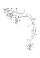
図1に示すように、内視鏡3の挿入部12は最先端に位置した先端部31と、この先端部31の手元側に位置した湾曲部32と、この湾曲部32の手元側に位置した軟性部33とを備える。また、先端部31の先端面には観察窓34、照明窓35及びチャンネル口36等が設けられ、一般的な内視鏡と同様の機能を備える。湾曲部32はその挿入部12の基端に設けられた図示しない操作部によって湾曲操作がなされる。 As shown in FIG. 1, the insertion portion 12 of the
また、図1に示すように、オーバーチューブ1において、処置具用導入ガイドチューブ2をそれぞれ挿通して誘導するチャンネル15a,15bの先端開口部41は前方に向かって開口するだけではなく、側方へ向かっても連続的に広く開口し、導入ガイドチューブ2の湾曲部21,22の湾曲動作を阻害しないようになっている。 Further, as shown in FIG. 1, in the
そして、図3に示すように、各チャンネル15a,15bの先端開口部41の内壁にはそのチャンネル15a,15bに挿通した処置具用導入ガイドチューブ2の挿入部17を押え付け、オーバーチューブ1にその導入ガイドチューブ2の挿入部17を解除可能に固定的に係止する係止手段が設けられている。つまり、導入ガイドチューブ2の挿入部17を位置決め固定するストッパ45が設けられている。このストッパ45はチャンネル15a,15bの内壁に沿って形成された弾性片46を有し、この弾性片46の先端には押当て摩擦部材47を取り付けている。弾性片46は通常、図3に示すように、チャンネル15a,15bの通路内に突き出さない位置に退避しているが、後述する押付け具48によってチャンネル15a,15b内に押し出されたときはそのチャンネル15a,15bに挿通した導入ガイドチューブ2の挿入部17に押し当って係止する状態になり、オーバーチューブ1に導入ガイドチューブ2の挿入部17を位置決め保持するようになっている。なお、このような位置決め保持手段は内視鏡3の挿入部12を挿通するチャンネル15cにも設けてもよい。 Then, as shown in FIG. 3, the
また、図3に示すように、上記押付け具48はチャンネル15a,15bの内壁に沿って弾性片46の背面側に向き合って形成されたガイド面51に沿ってオーバーチューブ1の前後方向へスライド自在に設置されている。押付け具48には上記弾性片46の背面に形成した傾斜面52に押し当る突起53が形成されている。そして。この押付け具48には操作ワイヤ54が連結されており、操作ワイヤ54によって押付け具48をスライド操作するようになっている。操作ワイヤ54はオーバーチューブ1内を通じて手元側部分に設けられた手元部5に導かれる。 As shown in FIG. 3, the
図1に示すように、オーバーチューブ1の手元部5には、上記操作ワイヤ54を進退操作するための操作手段としてワイヤ操作機構55が組み込まれている。このワイヤ操作機構55は操作レバー56により回動されるピニオンギア57と、このピニオンギア57によってスライド移動するラック58を備え、上記操作ワイヤ54がそのラック58に連結されている。この操作レバー56を回動することによってワイヤ操作機構55を操作することにより上記操作ワイヤ54を進退操作することができる。ここでは各チャンネル15a,15bのストッパ45それぞれのワイヤ操作機構55を1つの操作レバー56により操作するようにしてある。しかし、各チャンネル15a,15bのストッパ45毎に操作手段としての操作レバー56を個別的に設け、上記チャンネル15a,15bに挿通される器具の挿通部分をそれぞれ独立して解除可能に係止するようにしても良い。 As shown in FIG. 1, a wire operation mechanism 55 is incorporated in the
次に、上述した内視鏡治療装置を使用する場合について説明する。まず、最初に、体外で、オーバーチューブ1内に内視鏡3の挿入部12を挿通し、オーバーチューブ1の先端から挿入部12の先端側部分を予め突き出し、その観察機能のある内視鏡3の挿入部12の部分を腹腔などの体腔内に挿入する。その後に、内視鏡3の挿入部12に沿わせながら、オーバーチューブ1の方を体腔内に挿入する。一旦、オーバーチューブ1を体腔内に挿入して設置してしまえば、その後は、内視鏡3等の器具類を自由に抜き差しできる。 Next, the case where the endoscopic treatment apparatus described above is used will be described. First, outside the body, the insertion portion 12 of the
そして、このオーバーチューブ1を通じて体腔内に導入した内視鏡3により体腔内を観察して診断や手術を行なうことができる。また、処置具42を用いて診断や手術を行なう場合には、図1に示すように、オーバーチューブ1のチャンネル15a,15bを通じて、処置具用導入ガイドチューブ2を導入し、導入ガイドチューブ2の湾曲部21,22を含む先端側可動部分をオーバーチューブ1の先端開口部41から体腔内に突き出し、この処置具用導入ガイドチューブ2を通じて処置具42を体腔内まで挿入する。 Then, diagnosis and surgery can be performed by observing the inside of the body cavity by the
次に、オーバーチューブ1の手元部5の操作レバー56を操作し、ストッパ45により導入ガイドチューブ2をオーバーチューブ1に固定する。これにより、オーバーチューブ1に対する導入ガイドチューブ2の位置が定まり、導入ガイドチューブ2の位置が変わらない。その上で、導入ガイドチューブ2の湾曲部21,22を湾曲して処置具42の向きや位置を決める操作を行なって手術などの作業を行なう。 Next, the operation lever 56 of the
このようにオーバーチューブ1に対する導入ガイドチューブ2の位置が変わらないので、手術の最中に導入ガイドチューブ2の位置を調整し直す必要がなくなる。 Thus, since the position of the
本実施形態のように、複数の導入ガイドチューブ2を用いて複数の処置具42を使用する場合には一方の処置具42を操作している間、他方の処置具42を誘導した導入ガイドチューブ2の位置が変わり易いが、オーバーチューブ1に導入ガイドチューブ2を固定しておけるので、その不都合を解消できる。また、処置具42で生体組織を挙上する場合には、処置具42及びそれを操作する導入ガイドチューブ2に比較的大きい負荷がかかっても、その反作用により導入ガイドチューブ2の位置がずれることを阻止することができる。 In the case of using a plurality of treatment tools 42 using a plurality of
上述したように、上記実施形態の構成によれば、着脱操作可能な固定的係止手段を用いて、オーバーチューブ1を通じて案内される導入ガイドチューブ2が動いてしまうことを抑止できる。 As described above, according to the configuration of the above-described embodiment, it is possible to prevent the
なお、上記実施形態では、導入ガイドチューブ2をオーバーチューブ1に固定する場合について述べたが、同様の固定的な係止手段を用い、内視鏡3の挿入部についてもオーバーチューブ1に固定するようにしてもよい。 In the above embodiment, the case where the
次に、図4及び図5を参照して本発明の他の実施形態に係る内視鏡治療装置について説明する。上述した実施形態と同様なものについては同一の符号を付して説明する。 Next, an endoscopic treatment apparatus according to another embodiment of the present invention will be described with reference to FIGS. 4 and 5. The same components as those in the above-described embodiment will be described with the same reference numerals.
本実施形態ではオーバーチューブ1に形成した導入ガイドチューブ用チャンネルの先端開口周縁の全周にわたりバルーン61を付設し、このバルーン61を膨らませて導入ガイドチューブ2の挿入部17を押え付けてその導入ガイドチューブ2を固定的に係止する流体操作式の係止手段を構成したものである。上記バルーン61はオーバーチューブ1の外周またはその内部に配置したチューブ62に接続され、そのチューブ62による流体管路を通じて上記バルーン61に流体を供給したり排出したりすることができるようになっている。 In this embodiment, a
図5に示すように、チューブ62はオーバーチューブ1の外周に沿ってオーバーチューブ1の体外に位置する手元部63まで導かれ、その手元部63に設けた口金64に接続されている。そして、口金64にシリンジ65を接続し、このシリンジ65を用いてバルーン61に流体を給排するようになっている。 As shown in FIG. 5, the
図4に示すように、本実施形態では、オーバーチューブ1の先端部分には内視鏡3における挿入部の先端部31を保持する連結具66が着脱自在に取着されている。この連結具66を使用する場合、オーバーチューブ1に内視鏡3の挿入部を沿わせて配置し、オーバーチューブ1の先端に内視鏡3の湾曲部より先に位置する先端部31の部分を連結具66により、オーバーチューブ1の先端に係止して両者を一緒に体腔内に誘導することができる。また、オーバーチューブ1の先端から突き出す導入ガイドチューブ2または処置具42等の状況を内視鏡3によって監視することができる。 As shown in FIG. 4, in the present embodiment, a
また、図4に示すように、導入ガイドチューブ2の挿入部17をオーバーチューブ1内に挿通して適量、先端部20を突き出す。そして、導入ガイドチューブ2の前後の位置を決めた後、バルーン61に流体を供給して上記バルーン61を膨張させることによってその位置に導入ガイドチューブ2の挿入部17を固定することができる。また、バルーン61を収縮させておけば、オーバーチューブ1の先端開口は解放しており、導入ガイドチューブ2の進退移動を許容する。この実施形態の場合にも上述した実施形態の場合と同様、オーバーチューブ1に対する導入ガイドチューブ2の進退及び固定が可能であり、上述した実施形態の場合と同様の作用効果が得られる。 Further, as shown in FIG. 4, the
次に、図6及び図7を参照して本発明のさらに他の実施形態に係る内視鏡治療装置について説明する。上述した実施形態と同様なものについては同一の符号を付して説明する。 Next, an endoscope treatment apparatus according to still another embodiment of the present invention will be described with reference to FIGS. 6 and 7. The same components as those in the above-described embodiment will be described with the same reference numerals.
本実施形態は、上述したようなオーバーチューブの手元側部分を複数の個所で位置決め固定するようにした支持装置70の例である。すなわち、処置具用導入ガイドチューブ2を誘導する第1オーバーチューブ1aについてはその第1オーバーチューブ1aの挿入部4aにおける基端部の中途部分を把持する第1固定ホルダ71aと、第1のオーバーチューブ1aの手元部5aを把持する第1可動ホルダ72aとを備える。また、内視鏡3の挿入部を誘導する第2オーバーチューブ1bについてはその第2オーバーチューブ1bの挿入部4bにおける基端側中途部分を把持する第2固定ホルダ71bと、第2オーバーチューブ1bの手元部5bを把持する第2可動ホルダ72bとを備える。 The present embodiment is an example of a
上記第1固定ホルダ71aと第2固定ホルダ71bはいずれも伸縮リンク75や回動・固定が自在な球面軸受76等を用いた支持アーム77によってその支持位置が任意に選択できるように基台78に支持されている。支持アーム77はその固定ホルダ71a,71bの支持位置を変更することができるようになっていて、これは、第1支持位置調整手段を構成している。上記基台78はキャスタ79を備えており、床面上を移動自在である。 The first fixed
一方、第1可動ホルダ72aは第1リンク機構81を介して第1固定ホルダ71aに対して移動自在に支持されている。また、第2可動ホルダ72bは第2リンク機構82を介して第2固定ホルダ71bに対して移動自在に支持されている。このため、第1可動ホルダ72aと第2可動ホルダ72bは、上記固定ホルダ71a,71bを支点または基点として、オーバーチューブ1a,1bの手元部5a,5bを保持したまま動き得る。第1リンク機構81及び第2リンク機構82は可動ホルダ72a,72bの支持位置を変更することができるようになっていて、これは、第2支持位置調整手段を構成している。 On the other hand, the first
上記支持装置70の第1リンク機構81,82の可動部にはその移動に対して抵抗力を付加する摩擦力発生手段(図示せず)が組み込まれている。すなわち、導入ガイドチューブ2や内視鏡3を支持した状態で、操作者が手を離しても、上記可動ホルダ72a,72bはその位置で固定される。また、上記可動部には摩擦力を付与する固定状態と、上記可動部がフリーに動く固定解除状態を選択できる切換え操作可能な、例えば電磁式ブレーキ手段を組み込んでも良い。このブレーキ手段の操作は例えば支持装置70やその周辺に設置したスイッチなどの操作手段によって操作できるようにする。 Friction force generating means (not shown) for adding resistance to the movement is incorporated in the movable portions of the
また、第1リンク機構81,82の可動部が固定状態でも僅かに大きめの力を加えると、可動が可能な固定状態とし、上記可動ホルダ72a,72bが導入ガイドチューブ2や内視鏡3の手元部5a,5bを支持したまま動き得るように設定しても良い。 Further, even when the movable parts of the
また、図7に示すように、オーバーチューブ1a,1bの挿入部4a,4bの途中部分に筒状の保持部材83を取り付け、この保持部材83に形成した係止用穴84に固定ホルダ71a,71bの止ネジ85を嵌め込んで係着する。また、オーバーチューブ1a,1bの手元部5a,5bにも係止用穴86を形成し、この係止用穴86に対して可動ホルダ72a,72bの止ネジ87を嵌め込んで係着する。 In addition, as shown in FIG. 7, a
このような実施形態では上記支持装置70によってオーバーチューブ1a,1bの手元側部分を支持できるので、オーバーチューブ1a,1bの取り扱えが容易である。また、オーバーチューブ1a,1bの柔軟な挿入部4a,4bにおける基端側途中部分は固定ホルダ71a,71bで把持され、患者に対する位置が決まり、定位置で固定的に支持しておけるため、導入ガイドチューブ2や内視鏡3等の器具先端の位置を安定化させることができる。また、導入ガイドチューブ2や内視鏡3の手元部5a,5bは別の可動ホルダ72a,72bで把持するようにしたので、手術の作業状況に応じて自由に移動させて操作に最適な場所に保持可能である。このため、導入ガイドチューブ2や内視鏡3の操作性能を高めることができる。また、固定ホルダ71a,71bと可動ホルダ72a,72bの支持位置は互いに離れており、その固定ホルダ71a,71bと可動ホルダ72a,72bの間に柔軟な挿入部部分が存在するので、挿入部4a,4bの患者に近い先端側部分の安定性が増す。また、オーバーチューブ1a,1bを通じて導入ガイドチューブ2や内視鏡3を挿入する際、その手元部5a,5bを移動する手元操作が容易であると共に、その手元部5a,5bを操作する際の影響が、先端側に伝わることを遮断する。これによっても、オーバーチューブ1a,1bの柔軟な挿入部4a,4bの先端側部分を安定させることができる。 In such an embodiment, since the proximal side portions of the
さらに、固定ホルダ71a,71bに対して患者から離れた可動ホルダ72a,72bにより、オーバーチューブ1a,1bの手元部5a,5bを保持するので、術中、導入ガイドチューブ2や内視鏡3の手元部5a,5bから操作者が手を離しても、その姿勢にそのまま維持しておける。 Furthermore, since the
固定ホルダ71a,71bによる導入ガイドチューブ2や内視鏡3の支持位置は、通常、術中には変更しない。これは手術器具の先端の位置を安定化させるためである。しかし、患者に対する固定ホルダ71a,71bの位置は支持アーム77を操作することにより変更が可能である。 The support positions of the
一方、導入ガイドチューブ2や内視鏡3の手元部5a,5bは上記可動ホルダ72a,72bによって操作者が手を離してもその位置に維持できる。しかし、固定状態を解除してフリー状態を選択し、或いは固定状態でも外力を加えることにより動き得るようにした場合は大きめの力を加えると、可動ホルダ72a,72bは導入ガイドチューブ2や内視鏡3と一緒に追従して動かせる。 On the other hand, the
なお、この実施形態のオーバーチューブには上述した実施形態のストッパ機構等のチューブ固定手段を組み込むことが可能である。 In addition, tube fixing means such as the stopper mechanism of the above-described embodiment can be incorporated in the overtube of this embodiment.
次に、図8を参照して本発明のさらに他の実施形態に係る内視鏡治療装置について説明する。上述した実施形態と同様なものについては同一の符号を付して説明する。 Next, an endoscopic treatment apparatus according to still another embodiment of the present invention will be described with reference to FIG. The same components as those in the above-described embodiment will be described with the same reference numerals.
この実施形態ではオーバーチューブ1の先端の部分に連結具90を設け、この連結具90には内視鏡3の挿入部における先端部31を保持する把持片91を形成したものである。内視鏡3の先端部31に装着されたフード92を把持片91によって把持し、オーバーチューブ1と内視鏡3の両最先端同士を連結するようにした。これによれば、内視鏡3によってオーバーチューブ1の先端から突き出す導入ガイドチューブ2または処置具42等の器具の使用状況を容易に監視することができる。この実施形態のオーバーチューブには上述した実施形態のストッパ機構等のチューブ固定手段を組み込み適用が可能なものである。 In this embodiment, a
図9乃至12は本発明のさらに他の実施形態に係る内視鏡治療装置を示すものである。上述した実施形態と同様なものについては同一の符号を付して説明する。 9 to 12 show an endoscope treatment apparatus according to still another embodiment of the present invention. The same components as those in the above-described embodiment will be described with the same reference numerals.
本実施形態は患者用ベット101の上に載置できるオーバーチューブ用支持装置102の例である。図9に示すように、支持装置102は基台103を有し、この基台103には2本のオーバーチューブ1の挿入部4における中間部分を載置する1つの固定式の第1支持具104と、オーバーチューブ1の手元部5をそれぞれ別々に支持する複数の可動式の第2支持具105とが設けられている。第1支持具104は患者の近くに配置され、複数のオーバーチューブ1を一緒に保持できる。この第1支持具104はオーバーチューブ1を下から受ける台106と上側へ回動して開閉自在な蓋状の押え部材107を備える。また、第2支持具105は互いに離れて配置されると共に、第1支持具104からも離れて配置される。 This embodiment is an example of an
図10に示すように、第2支持具105は、オーバーチューブ1の手元部5を把持する開閉自在な把持具111を備える。図11はその把持具111を開き、これにオーバーチューブ1の手元部5を載置しようとする状況を示している。 As shown in FIG. 10, the
上記把持具111は基台103に取り付けた支持アーム113の先端に保持されている。この支持アーム113は図10に示すように複数のアーム114と把持具111を順次枢着することにより各アーム114及び把持具111の回動方向を異ならせることにより把持具111の位置を自由に変更することができる。また、支持アーム113の各連結部には、術者が任意に所定の摩擦力の付勢と解除が可能な、例えば電磁式ブレーキ手段(図示せず)が設けられていて、このブレーキ手段を選択的に操作することにより、必要時、支持アーム113の相対的な移動を許容し、またはその相対的な移動を抑制できるようになっている。 The
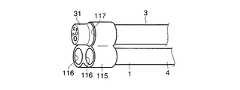
図12は2本のオーバーチューブ1の先端と内視鏡3における挿入部の先端部31を束ねる連結具115の例を示している。連結具115は2本のオーバーチューブ1の先端部分をそれぞれ別々に嵌め込む2つの挿入孔116と、内視鏡3の先端部31を嵌め込む1つの挿入孔117を有している。 FIG. 12 shows an example of a
このような実施形態ではオーバーチューブ1の手元側部分を支持装置102によって支持できるのでオーバーチューブ1の取り扱いが容易である。また、オーバーチューブ1の柔軟な挿入部4における途中部分を第1支持具104で把持すると共に手元部5を別々の連結具115で把持するようにした。したがって、患者に近い柔軟な挿入部4の部分を固定的に支持しておける。また、第1支持具104と第2支持具105は間隔をあけ離れているので、この間には導入ガイドチューブ2や内視鏡3の柔軟な挿入部の部分が存在する。したがって、オーバーチューブ1を通じて挿入する導入ガイドチューブ2や内視鏡3の手元部5を移動する操作による影響を遮断し、オーバーチューブ1の柔軟な挿入部4の先端側を安定させることができる。さらに、オーバーチューブ1の手元部5を可動自在な第2支持具105で把持しているので、オーバーチューブ1を通じて挿入する導入ガイドチューブ2や内視鏡3の手元部5を自由に移動させる操作が可能になり、導入ガイドチューブ2や内視鏡3の操作性を確保することができる。 In such an embodiment, since the proximal side portion of the
なお、この実施形態のオーバーチューブ1には上述した実施形態のストッパ機構等のチューブ固定手段を組み込み、適用可能なものである。 In addition, tube fixing means, such as the stopper mechanism of embodiment mentioned above, is incorporated in the
図13は本発明のさらに他の実施形態に係る支持装置を示すものである。上述した実施形態と同様なものについては同一の符号を付して説明する。 FIG. 13 shows a support device according to still another embodiment of the present invention. The same components as those in the above-described embodiment will be described with the same reference numerals.
この実施形態ではオーバーチューブ1の挿入部4における中間部分を保持する第1支持具121と、オーバーチューブ1の手元部5を支持する第2支持具122とが設けられている。第1支持具121は患者の近くに配置され、第2支持具122はその第1支持具121から離れて配置されている。 In this embodiment, a
第1支持具121と第2支持具122はいずれも天井から吊持される別々の支持アーム123,124の先端にそれぞれ保持されている。支持アーム123,124はいずれも図13に示すように複数のアーム125を順次枢着することにより各アーム125の回動方向を適宜異ならせることにより支持具121,122の位置を自由に変更できるようになっている。また、支持アーム123,124の連結部には、術者が任意に所定の摩擦力の付勢と解除が可能なブレーキ手段(図示せず)が設けられていて、このブレーキ手段を操作することにより、必要時、支持アーム123,124の相対的な移動を許容し、またはその相対的な移動を抑制できるようになっている。 Both the
この実施形態でも天井から吊持する点の相違はあるものの先に述べたと同様の作用効果を奏する。また、支持具121,122を天井から吊持するのでそれらの部材が邪魔になり難い。この実施形態のオーバーチューブには上述した実施形態のストッパ機構等のチューブ固定手段を組み込み適用が可能なものである。 Even in this embodiment, although there is a difference in that it is suspended from the ceiling, the same effects as described above can be obtained. Moreover, since the
なお、本発明は、前述したものに限定されず、他の形態にも適用が可能である。 In addition, this invention is not limited to what was mentioned above, It is applicable to another form.
〔付記〕
1.器具を体腔内に誘導する軟性の誘導用チューブにおいて、上記誘導用チューブの先端部に、そのチューブを通じて誘導される器具の挿通部分を、解除可能に上記チューブに対し係止する係止手段を設けたことを特徴とする誘導用チューブ。
2.上記係止手段による係止とその解除を操作する操作手段を、上記チューブの手元側に設けたことを特徴とする第1項に記載の誘導用チューブ。
3.上記係止手段は、上記チューブの先端開口部の内壁に沿って配置された弾性片と、上記チューブを通じて誘導される器具の挿通部分に上記弾性片を押し当てる押付具とを備えることを特徴とする第1項または第2項に記載の誘導用チューブ。
4.上記係止手段は、上記チューブの先端開口部に設けたバルーンを含むことを特徴とする第1項または第2項に記載の誘導用チューブ。
5.上記チューブを通じて誘導される器具は、内視鏡を含むことを特徴とする第1〜4項のいずれかに記載の誘導用チューブ。
6.上記チューブを通じて誘導される器具は、処置具用挿通ルーメンを有し、かつ、手元側から湾曲操作可能な湾曲部を有した処置具用導入ガイドチューブを含むことを特徴とする第1〜4項のいずれかに記載の誘導用チューブ。
7.上記固定手段は、上記チューブの手元部に設けた操作手段に接続されたワイヤを介して操作されるものであることを特徴とする第1〜4項のいずれかに記載の誘導用チューブ。
8.上記係止手段は、上記チューブに配置された管路を通じて流体により操作されるものであることを特徴とする第1〜4項のいずれかに記載の誘導用チューブ。
9.上記チューブは複数のチャンネルを有し、上記係止手段は上記チャンネルに挿通される器具の挿通部分を解除可能に係止するようにしたことを特徴とする第1〜8項のいずれかに記載の誘導用チューブ。
10.上記係止手段は上記チャンネルに挿通される器具の挿通部分をそれぞれ独立して解除可能に係止するようにしたことを特徴とする第9項のいずれかに記載の誘導用チューブ。
11.処置具を体腔内に誘導すると共に先端付近に湾曲機能を備えた軟性の導入ガイドチューブと、この導入ガイドチューブを体腔内に誘導すると共に上記導入ガイドチューブを解除可能に上記チューブに対し係止する係止手段を有した軟性の誘導用チューブと、を備えることを特徴とする治療システム。[Appendix]
1. In a flexible guide tube for guiding an instrument into a body cavity, a locking means for releasably locking the insertion portion of the instrument guided through the tube to the tube is provided at the distal end of the guide tube. A guide tube characterized by that.
2. 2. The guide tube according to
3. The locking means includes an elastic piece disposed along the inner wall of the distal end opening of the tube, and a pressing tool that presses the elastic piece against an insertion portion of an instrument guided through the tube. The guide tube according to
4). 3. The guiding tube according to
5). The guiding tube according to any one of
6). The instrument guided through the tube includes a treatment instrument introduction guide tube having a treatment instrument insertion lumen and a bending portion that can be bent from the proximal side. The guide tube according to any one of the above.
7). The guide tube according to any one of
8). The guide tube according to any one of
9. 9. The tube according to
10. 10. The guide tube according to any one of claims 9 to 9, wherein the locking means is configured to lock the insertion portions of the instruments inserted through the channels so that they can be released independently of each other.
11. A flexible introduction guide tube that guides the treatment tool into the body cavity and has a bending function near the distal end thereof, and guides the introduction guide tube into the body cavity and releasably engages the introduction guide tube with the tube. A treatment system comprising: a flexible guide tube having locking means.
12.上記誘導用チューブの手元側付近で上記誘導用チューブの軟性挿入部の中途部分を支持する第1ホルダと、上記誘導用チューブの手元部を支持する第2ホルダとを有し、上記第1ホルダに対して上記第2ホルダの位置が変更自在である支持装置を備えたことを特徴とする第11項に記載の治療システム。
13.上記第1ホルダによる上記誘導用チューブの支持位置を変更可能な第1支持位置調整手段を備えたことを特徴とする第12項に記載の治療システム。
14.上記第2ホルダによる上記誘導用チューブの支持位置を変更可能な第2支持位置調整手段を備えたことを特徴とする第12項または第13項に記載の治療システム。
15.上記第1ホルダに対する上記第2ホルダの位置を変更自在に支持する支持装置を備えたことを特徴とする第12項、第13項または第14項に記載の治療システム。
16.上記第1ホルダに対する上記第2ホルダの位置を定めて固定する固定力を付加する手段と、上記固定力を解除する手段と、上記付加手段と上記解除手段を選択する操作手段とを備えたことを特徴とする第15項に記載の治療システム。
17.上記第2ホルダの位置を固定する固定状態とその固定を解除する状態を選択する操作手段を備えたことを特徴とする第15項に記載の治療システム。12 A first holder for supporting a middle portion of the flexible insertion portion of the guide tube near the proximal side of the guide tube; and a second holder for supporting the proximal portion of the guide tube, the first holder The treatment system according to item 11, further comprising a support device capable of changing the position of the second holder.
13. 13. The treatment system according to item 12, further comprising first support position adjusting means capable of changing a support position of the guide tube by the first holder.
14 14. The treatment system according to item 12 or 13, further comprising second support position adjusting means capable of changing a support position of the guide tube by the second holder.
15. The treatment system according to item 12, 13, or 14, further comprising a support device that supports the position of the second holder with respect to the first holder in a changeable manner.
16. Means for applying a fixing force for determining and fixing the position of the second holder with respect to the first holder; means for releasing the fixing force; and an operating means for selecting the adding means and the releasing means. Item 16. The treatment system according to item 15,
17. 16. The treatment system according to item 15, further comprising operation means for selecting a fixed state for fixing the position of the second holder and a state for releasing the fixation.
1…オーバーチューブ、2…導入ガイドチューブ、3…内視鏡
4…挿入部、5…手元部、11…内視鏡、45…ストッパ
46…弾性片、48…押付け具、51…ガイド面、52…傾斜面
53…突起、54…操作ワイヤ、55…ワイヤ操作機構、56…操作レバー
57…ピニオンギア、58…ラック、61…バルーン、62…チューブ。DESCRIPTION OF
Claims (6)
Translated fromJapanesePriority Applications (4)
| Application Number | Priority Date | Filing Date | Title |
|---|---|---|---|
| JP2004110426AJP4652713B2 (en) | 2004-04-02 | 2004-04-02 | Endoscopic treatment device |
| DE602005009595TDE602005009595D1 (en) | 2004-04-02 | 2005-03-21 | Medical system with cladding tube |
| EP05006143AEP1582138B1 (en) | 2004-04-02 | 2005-03-21 | Medical system with over-tube |
| US11/093,824US20050222495A1 (en) | 2004-04-02 | 2005-03-30 | Medical system with over-tube |
Applications Claiming Priority (1)
| Application Number | Priority Date | Filing Date | Title |
|---|---|---|---|
| JP2004110426AJP4652713B2 (en) | 2004-04-02 | 2004-04-02 | Endoscopic treatment device |
Publications (2)
| Publication Number | Publication Date |
|---|---|
| JP2005287963Atrue JP2005287963A (en) | 2005-10-20 |
| JP4652713B2 JP4652713B2 (en) | 2011-03-16 |
Family
ID=34880138
Family Applications (1)
| Application Number | Title | Priority Date | Filing Date |
|---|---|---|---|
| JP2004110426AExpired - Fee RelatedJP4652713B2 (en) | 2004-04-02 | 2004-04-02 | Endoscopic treatment device |
Country Status (4)
| Country | Link |
|---|---|
| US (1) | US20050222495A1 (en) |
| EP (1) | EP1582138B1 (en) |
| JP (1) | JP4652713B2 (en) |
| DE (1) | DE602005009595D1 (en) |
Cited By (30)
| Publication number | Priority date | Publication date | Assignee | Title |
|---|---|---|---|---|
| WO2007080974A1 (en)* | 2006-01-13 | 2007-07-19 | Olympus Medical Systems Corp. | Treatment endoscope |
| JP2008125819A (en)* | 2006-11-21 | 2008-06-05 | Kobe Univ | Overtube |
| JP2009153924A (en)* | 2007-12-27 | 2009-07-16 | Olympus Medical Systems Corp | Endoscope body and endoscope |
| JP2009268592A (en)* | 2008-05-01 | 2009-11-19 | Olympus Medical Systems Corp | Endoscope system |
| JP2011078576A (en)* | 2009-10-07 | 2011-04-21 | Kyorin Gakuen | Detachable treatment hood for endoscope |
| US8021293B2 (en) | 2006-01-13 | 2011-09-20 | Olympus Medical Systems Corp. | Medical treatment endoscope |
| US8092371B2 (en) | 2006-01-13 | 2012-01-10 | Olympus Medical Systems Corp. | Medical treatment endoscope |
| JP2013514150A (en)* | 2009-12-18 | 2013-04-25 | クック メディカル テクノロジーズ エルエルシー | Endoscope sheath |
| US8439828B2 (en) | 2006-01-13 | 2013-05-14 | Olympus Medical Systems Corp. | Treatment endoscope |
| WO2013132992A1 (en)* | 2012-03-08 | 2013-09-12 | オリンパスメディカルシステムズ株式会社 | Guide sheath and medical system |
| US8556805B2 (en) | 2006-01-13 | 2013-10-15 | Olympus Medical Systems Corp. | Rotational force transmission mechanism, force-attenuating apparatus, medical device, and medical instrument-operation mechanism |
| WO2013176167A1 (en)* | 2012-05-25 | 2013-11-28 | 富士フイルム株式会社 | Endoscopic surgery device and outer sleeve tube |
| WO2015033910A1 (en)* | 2013-09-03 | 2015-03-12 | 富士フイルム株式会社 | Endoscopic surgical device and outer sleeve |
| WO2015033907A1 (en)* | 2013-09-03 | 2015-03-12 | 富士フイルム株式会社 | Endoscopic surgical device and outer sleeve |
| WO2015033908A1 (en)* | 2013-09-03 | 2015-03-12 | 富士フイルム株式会社 | Endoscopic surgical device, outer sleeve and endoscope |
| WO2015033909A1 (en)* | 2013-09-03 | 2015-03-12 | 富士フイルム株式会社 | Endoscopic surgical device and outer sleeve |
| US9173550B2 (en) | 2006-01-13 | 2015-11-03 | Olympus Corporation | Medical apparatus |
| US9289112B2 (en) | 2006-01-13 | 2016-03-22 | Olympus Corporation | Medical treatment endoscope having an operation stick formed to allow a procedure instrument to pass |
| US9308049B2 (en) | 2006-01-13 | 2016-04-12 | Olympus Corporation | Medical treatment endoscope |
| WO2016114089A1 (en)* | 2015-01-16 | 2016-07-21 | オリンパス株式会社 | Over tube and manipulator system |
| JP2017006729A (en)* | 2013-09-03 | 2017-01-12 | 富士フイルム株式会社 | Endoscopic surgical apparatus and sheath tube |
| WO2017119108A1 (en)* | 2016-01-07 | 2017-07-13 | 学校法人慶應義塾 | Endoscope treatment device |
| CN107205789A (en)* | 2015-06-01 | 2017-09-26 | 奥林巴斯株式会社 | Medical manipulator system |
| WO2018079045A1 (en)* | 2016-10-26 | 2018-05-03 | 国立大学法人九州大学 | Fixing base |
| JP2018075429A (en)* | 2011-04-06 | 2018-05-17 | メドロボティクス コーポレイション | System for performing medical procedure |
| US10258369B2 (en) | 2013-09-03 | 2019-04-16 | Fujifilm Corporation | Endoscopic surgical device and overtube |
| US10264950B2 (en) | 2013-03-29 | 2019-04-23 | Fujifilm Corporation | Endoscopic surgery device |
| WO2021193822A1 (en)* | 2020-03-27 | 2021-09-30 | 日本ゼオン株式会社 | Mounting member for endoscope |
| JP2022041104A (en)* | 2020-08-31 | 2022-03-11 | 学校法人慶應義塾 | Treatment tool insertion aid |
| WO2023032145A1 (en)* | 2021-09-03 | 2023-03-09 | オリンパス株式会社 | Treatment apparatus, treatment tool manipulation device, treatment system, and treatment tool manipulation method |
Families Citing this family (67)
| Publication number | Priority date | Publication date | Assignee | Title |
|---|---|---|---|---|
| WO2004021873A2 (en) | 2002-09-06 | 2004-03-18 | C.R. Bard, Inc. | Integrated endoscope and accessory treatment device |
| WO2004060040A2 (en)* | 2002-12-30 | 2004-07-22 | Fannie Mae | System and method for processing data pertaining to financial assets |
| US8562516B2 (en)* | 2004-04-14 | 2013-10-22 | Usgi Medical Inc. | Methods and apparatus for obtaining endoluminal access |
| US8512229B2 (en)* | 2004-04-14 | 2013-08-20 | Usgi Medical Inc. | Method and apparatus for obtaining endoluminal access |
| US8277373B2 (en) | 2004-04-14 | 2012-10-02 | Usgi Medical, Inc. | Methods and apparaus for off-axis visualization |
| US20050272977A1 (en)* | 2004-04-14 | 2005-12-08 | Usgi Medical Inc. | Methods and apparatus for performing endoluminal procedures |
| US8641728B2 (en)* | 2005-06-13 | 2014-02-04 | Ethicon Endo-Surgery, Inc. | Attachment apparatus for coupling with an endoscope |
| US7846169B2 (en) | 2005-06-13 | 2010-12-07 | Ethicon Endo-Surgery, Inc. | Adjustable vacuum chamber for a surgical suturing apparatus |
| US7628796B2 (en) | 2005-06-13 | 2009-12-08 | Ethicon Endo-Surgery, Inc. | Surgical suturing apparatus with anti-backup system |
| US20060282097A1 (en) | 2005-06-13 | 2006-12-14 | Ortiz Mark S | Surgical suturing apparatus with a non-visible spectrum sensing member |
| US9545191B2 (en) | 2005-06-13 | 2017-01-17 | Ethicon Endo-Surgery, Inc. | Method for suture lacing |
| US7615060B2 (en) | 2005-06-13 | 2009-11-10 | Ethicon-Endo Surgery, Inc. | Endoscopic suturing device |
| US7766925B2 (en) | 2005-06-13 | 2010-08-03 | Ethicon Endo-Surgery, Inc. | Surgical suturing apparatus |
| US20070088373A1 (en)* | 2005-10-18 | 2007-04-19 | Endogastric Solutions, Inc. | Invaginator for gastroesophageal flap valve restoration device |
| AU2007201312B2 (en) | 2006-03-31 | 2012-08-30 | Ethicon Endo-Surgery, Inc. | Method for suture lacing |
| CA2650474A1 (en) | 2006-04-24 | 2007-11-08 | Synecor, Llc | Natural orifice surgical system |
| US8518024B2 (en) | 2006-04-24 | 2013-08-27 | Transenterix, Inc. | System and method for multi-instrument surgical access using a single access port |
| US7753843B2 (en)* | 2006-05-09 | 2010-07-13 | Boston Scientific Scimed, Inc. | Medical device positioning system |
| US7927271B2 (en) | 2006-05-17 | 2011-04-19 | C.R. Bard, Inc. | Endoscope tool coupling |
| KR101477133B1 (en)* | 2006-06-13 | 2014-12-29 | 인튜어티브 서지컬 인코포레이티드 | Minimally invasive surgical system |
| US9456877B2 (en) | 2006-12-01 | 2016-10-04 | Boston Scientific Scimed, Inc. | Direct drive instruments and methods of use |
| US7976458B2 (en)* | 2006-12-05 | 2011-07-12 | Ethicon Endo-Surgery, Inc. | Independent articulating accessory channel |
| US20080147018A1 (en)* | 2006-12-15 | 2008-06-19 | Squilla John R | Laparoscopic cannula with camera and lighting |
| US8007432B2 (en) | 2007-01-26 | 2011-08-30 | Ethicon Endo-Surgery, Inc. | Endoscopic accessory control mechanism |
| US7655004B2 (en) | 2007-02-15 | 2010-02-02 | Ethicon Endo-Surgery, Inc. | Electroporation ablation apparatus, system, and method |
| JP2008259701A (en)* | 2007-04-12 | 2008-10-30 | Olympus Corp | Apparatus inserted into living body |
| EP3375479B1 (en) | 2007-05-18 | 2023-03-22 | Boston Scientific Scimed, Inc. | Medical drive systems |
| DE102007029162A1 (en)* | 2007-06-25 | 2009-01-08 | Tahar Benhidjeb | Surgical instrument |
| US8579897B2 (en) | 2007-11-21 | 2013-11-12 | Ethicon Endo-Surgery, Inc. | Bipolar forceps |
| US20090112059A1 (en) | 2007-10-31 | 2009-04-30 | Nobis Rudolph H | Apparatus and methods for closing a gastrotomy |
| US8480657B2 (en) | 2007-10-31 | 2013-07-09 | Ethicon Endo-Surgery, Inc. | Detachable distal overtube section and methods for forming a sealable opening in the wall of an organ |
| US8287469B2 (en) | 2008-01-09 | 2012-10-16 | Ethicon Endo-Surgery, Inc. | Articulating surgical device and method of use |
| JP5128979B2 (en)* | 2008-02-15 | 2013-01-23 | オリンパスメディカルシステムズ株式会社 | Rotating self-propelled endoscope |
| US8679003B2 (en) | 2008-05-30 | 2014-03-25 | Ethicon Endo-Surgery, Inc. | Surgical device and endoscope including same |
| US8771260B2 (en) | 2008-05-30 | 2014-07-08 | Ethicon Endo-Surgery, Inc. | Actuating and articulating surgical device |
| US8906035B2 (en) | 2008-06-04 | 2014-12-09 | Ethicon Endo-Surgery, Inc. | Endoscopic drop off bag |
| US8361112B2 (en) | 2008-06-27 | 2013-01-29 | Ethicon Endo-Surgery, Inc. | Surgical suture arrangement |
| US8888792B2 (en) | 2008-07-14 | 2014-11-18 | Ethicon Endo-Surgery, Inc. | Tissue apposition clip application devices and methods |
| JP2010029382A (en)* | 2008-07-28 | 2010-02-12 | Olympus Medical Systems Corp | Endoscope insertion aid and endoscope apparatus |
| US8409200B2 (en) | 2008-09-03 | 2013-04-02 | Ethicon Endo-Surgery, Inc. | Surgical grasping device |
| US20100137681A1 (en)* | 2008-11-21 | 2010-06-03 | Usgi Medical, Inc. | Endoscopic instrument management system |
| US8157834B2 (en) | 2008-11-25 | 2012-04-17 | Ethicon Endo-Surgery, Inc. | Rotational coupling device for surgical instrument with flexible actuators |
| US8361066B2 (en) | 2009-01-12 | 2013-01-29 | Ethicon Endo-Surgery, Inc. | Electrical ablation devices |
| US20110098704A1 (en) | 2009-10-28 | 2011-04-28 | Ethicon Endo-Surgery, Inc. | Electrical ablation devices |
| US8608652B2 (en) | 2009-11-05 | 2013-12-17 | Ethicon Endo-Surgery, Inc. | Vaginal entry surgical devices, kit, system, and method |
| US8353487B2 (en) | 2009-12-17 | 2013-01-15 | Ethicon Endo-Surgery, Inc. | User interface support devices for endoscopic surgical instruments |
| US8496574B2 (en) | 2009-12-17 | 2013-07-30 | Ethicon Endo-Surgery, Inc. | Selectively positionable camera for surgical guide tube assembly |
| US9028483B2 (en) | 2009-12-18 | 2015-05-12 | Ethicon Endo-Surgery, Inc. | Surgical instrument comprising an electrode |
| US8506564B2 (en) | 2009-12-18 | 2013-08-13 | Ethicon Endo-Surgery, Inc. | Surgical instrument comprising an electrode |
| US9005198B2 (en) | 2010-01-29 | 2015-04-14 | Ethicon Endo-Surgery, Inc. | Surgical instrument comprising an electrode |
| JP6167041B2 (en)* | 2010-11-11 | 2017-07-19 | メドロボティクス コーポレイション | Introduction assembly for articulated robotic probes |
| US10092291B2 (en) | 2011-01-25 | 2018-10-09 | Ethicon Endo-Surgery, Inc. | Surgical instrument with selectively rigidizable features |
| US9233241B2 (en) | 2011-02-28 | 2016-01-12 | Ethicon Endo-Surgery, Inc. | Electrical ablation devices and methods |
| US9314620B2 (en) | 2011-02-28 | 2016-04-19 | Ethicon Endo-Surgery, Inc. | Electrical ablation devices and methods |
| US9254169B2 (en) | 2011-02-28 | 2016-02-09 | Ethicon Endo-Surgery, Inc. | Electrical ablation devices and methods |
| US9049987B2 (en) | 2011-03-17 | 2015-06-09 | Ethicon Endo-Surgery, Inc. | Hand held surgical device for manipulating an internal magnet assembly within a patient |
| US9259240B2 (en)* | 2011-03-29 | 2016-02-16 | Covidien Lp | Articulating surgical access system for laparoscopic surgery |
| US9427255B2 (en) | 2012-05-14 | 2016-08-30 | Ethicon Endo-Surgery, Inc. | Apparatus for introducing a steerable camera assembly into a patient |
| US9078662B2 (en) | 2012-07-03 | 2015-07-14 | Ethicon Endo-Surgery, Inc. | Endoscopic cap electrode and method for using the same |
| US9545290B2 (en) | 2012-07-30 | 2017-01-17 | Ethicon Endo-Surgery, Inc. | Needle probe guide |
| US10314649B2 (en) | 2012-08-02 | 2019-06-11 | Ethicon Endo-Surgery, Inc. | Flexible expandable electrode and method of intraluminal delivery of pulsed power |
| US9572623B2 (en) | 2012-08-02 | 2017-02-21 | Ethicon Endo-Surgery, Inc. | Reusable electrode and disposable sheath |
| US9277957B2 (en) | 2012-08-15 | 2016-03-08 | Ethicon Endo-Surgery, Inc. | Electrosurgical devices and methods |
| US10098527B2 (en) | 2013-02-27 | 2018-10-16 | Ethidcon Endo-Surgery, Inc. | System for performing a minimally invasive surgical procedure |
| US9788856B2 (en) | 2014-03-11 | 2017-10-17 | Stryker European Holdings I, Llc | Endoscopic surgical systems and methods |
| WO2019003308A1 (en)* | 2017-06-27 | 2019-01-03 | オリンパス株式会社 | Medical instrument for endoscope |
| WO2019133439A1 (en)* | 2017-12-29 | 2019-07-04 | The Board Of Regents Of The Unviversity Of Texas | End effector and end effector drive apparatus |
Citations (15)
| Publication number | Priority date | Publication date | Assignee | Title |
|---|---|---|---|---|
| JPS57188231A (en)* | 1981-05-14 | 1982-11-19 | Olympus Optical Co | Treating tool guide apparatus of endoscope |
| JPS63230163A (en)* | 1987-03-19 | 1988-09-26 | オリンパス光学工業株式会社 | Hyperthermia apparatus in body cavity |
| JPH01152413A (en)* | 1987-12-09 | 1989-06-14 | Olympus Optical Co Ltd | Guide tube for endoscope |
| JPH02239874A (en)* | 1989-03-13 | 1990-09-21 | Olympus Optical Co Ltd | Biotube expander and biotube expanding device |
| US5353783A (en)* | 1991-12-09 | 1994-10-11 | Nakao Naomi L | Endoscopic method using sheath |
| JPH06339456A (en)* | 1993-06-01 | 1994-12-13 | Olympus Optical Co Ltd | Apparatus for endoscopy |
| JPH078442A (en)* | 1993-06-22 | 1995-01-13 | Olympus Optical Co Ltd | Endoscope inspection system |
| JPH11192203A (en)* | 1997-10-31 | 1999-07-21 | Olympus Optical Co Ltd | Endoscope |
| JP2000033071A (en)* | 1998-07-17 | 2000-02-02 | Olympus Optical Co Ltd | Endoscope therapeutic device |
| JP2000325303A (en)* | 1999-05-17 | 2000-11-28 | Olympus Optical Co Ltd | Endoscopic therapeutic device |
| WO2001023027A1 (en)* | 1999-09-27 | 2001-04-05 | Essex Technology, Inc. | Rotate-to-advance catheterization system |
| JP2001275942A (en)* | 2000-03-31 | 2001-10-09 | Olympus Optical Co Ltd | Endoscope fixing tool |
| JP2002034905A (en)* | 2000-04-17 | 2002-02-05 | Olympus Optical Co Ltd | Endoscope and its endoscope system |
| JP2003305002A (en)* | 2002-04-17 | 2003-10-28 | Olympus Optical Co Ltd | Endoscope |
| JP2004065679A (en)* | 2002-08-07 | 2004-03-04 | Olympus Corp | Endoscope treatment system |
Family Cites Families (10)
| Publication number | Priority date | Publication date | Assignee | Title |
|---|---|---|---|---|
| US2003114A (en)* | 1934-11-26 | 1935-05-28 | Samuel J Goldsmith | Garment protector |
| DE4137426C1 (en)* | 1991-11-14 | 1993-02-11 | Richard Wolf Gmbh, 7134 Knittlingen, De | |
| US5957832A (en)* | 1993-10-08 | 1999-09-28 | Heartport, Inc. | Stereoscopic percutaneous visualization system |
| US6090063A (en)* | 1995-12-01 | 2000-07-18 | C. R. Bard, Inc. | Device, system and method for implantation of filaments and particles in the body |
| US5779624A (en)* | 1996-12-05 | 1998-07-14 | Boston Scientific Corporation | Sigmoid splint device for endoscopy |
| US6149581A (en)* | 1997-06-12 | 2000-11-21 | Klingenstein; Ralph James | Device and method for access to the colon and small bowel of a patient |
| US5913866A (en)* | 1997-06-19 | 1999-06-22 | Cardiothoracic Systems, Inc. | Devices and methods for harvesting vascular conduits |
| US6361488B1 (en)* | 2000-01-28 | 2002-03-26 | Endius Incorporated | Support apparatus for endoscopic surgery |
| JP3679674B2 (en)* | 2000-02-03 | 2005-08-03 | オリンパス株式会社 | Endoscope |
| US6461294B1 (en)* | 2000-10-30 | 2002-10-08 | Vision Sciences, Inc. | Inflatable member for an endoscope sheath |
- 2004
- 2004-04-02JPJP2004110426Apatent/JP4652713B2/ennot_activeExpired - Fee Related
- 2005
- 2005-03-21EPEP05006143Apatent/EP1582138B1/ennot_activeExpired - Lifetime
- 2005-03-21DEDE602005009595Tpatent/DE602005009595D1/ennot_activeExpired - Lifetime
- 2005-03-30USUS11/093,824patent/US20050222495A1/ennot_activeAbandoned
Patent Citations (15)
| Publication number | Priority date | Publication date | Assignee | Title |
|---|---|---|---|---|
| JPS57188231A (en)* | 1981-05-14 | 1982-11-19 | Olympus Optical Co | Treating tool guide apparatus of endoscope |
| JPS63230163A (en)* | 1987-03-19 | 1988-09-26 | オリンパス光学工業株式会社 | Hyperthermia apparatus in body cavity |
| JPH01152413A (en)* | 1987-12-09 | 1989-06-14 | Olympus Optical Co Ltd | Guide tube for endoscope |
| JPH02239874A (en)* | 1989-03-13 | 1990-09-21 | Olympus Optical Co Ltd | Biotube expander and biotube expanding device |
| US5353783A (en)* | 1991-12-09 | 1994-10-11 | Nakao Naomi L | Endoscopic method using sheath |
| JPH06339456A (en)* | 1993-06-01 | 1994-12-13 | Olympus Optical Co Ltd | Apparatus for endoscopy |
| JPH078442A (en)* | 1993-06-22 | 1995-01-13 | Olympus Optical Co Ltd | Endoscope inspection system |
| JPH11192203A (en)* | 1997-10-31 | 1999-07-21 | Olympus Optical Co Ltd | Endoscope |
| JP2000033071A (en)* | 1998-07-17 | 2000-02-02 | Olympus Optical Co Ltd | Endoscope therapeutic device |
| JP2000325303A (en)* | 1999-05-17 | 2000-11-28 | Olympus Optical Co Ltd | Endoscopic therapeutic device |
| WO2001023027A1 (en)* | 1999-09-27 | 2001-04-05 | Essex Technology, Inc. | Rotate-to-advance catheterization system |
| JP2001275942A (en)* | 2000-03-31 | 2001-10-09 | Olympus Optical Co Ltd | Endoscope fixing tool |
| JP2002034905A (en)* | 2000-04-17 | 2002-02-05 | Olympus Optical Co Ltd | Endoscope and its endoscope system |
| JP2003305002A (en)* | 2002-04-17 | 2003-10-28 | Olympus Optical Co Ltd | Endoscope |
| JP2004065679A (en)* | 2002-08-07 | 2004-03-04 | Olympus Corp | Endoscope treatment system |
Cited By (64)
| Publication number | Priority date | Publication date | Assignee | Title |
|---|---|---|---|---|
| US8617054B2 (en) | 2006-01-13 | 2013-12-31 | Olympus Medical Systems Corp. | Medical treatment endoscope |
| US9289112B2 (en) | 2006-01-13 | 2016-03-22 | Olympus Corporation | Medical treatment endoscope having an operation stick formed to allow a procedure instrument to pass |
| US9308049B2 (en) | 2006-01-13 | 2016-04-12 | Olympus Corporation | Medical treatment endoscope |
| US9173550B2 (en) | 2006-01-13 | 2015-11-03 | Olympus Corporation | Medical apparatus |
| WO2007080974A1 (en)* | 2006-01-13 | 2007-07-19 | Olympus Medical Systems Corp. | Treatment endoscope |
| US8021293B2 (en) | 2006-01-13 | 2011-09-20 | Olympus Medical Systems Corp. | Medical treatment endoscope |
| US8092371B2 (en) | 2006-01-13 | 2012-01-10 | Olympus Medical Systems Corp. | Medical treatment endoscope |
| JP5134971B2 (en)* | 2006-01-13 | 2013-01-30 | オリンパスメディカルシステムズ株式会社 | Treatment endoscope |
| US8556805B2 (en) | 2006-01-13 | 2013-10-15 | Olympus Medical Systems Corp. | Rotational force transmission mechanism, force-attenuating apparatus, medical device, and medical instrument-operation mechanism |
| US8439828B2 (en) | 2006-01-13 | 2013-05-14 | Olympus Medical Systems Corp. | Treatment endoscope |
| US8444547B2 (en) | 2006-01-13 | 2013-05-21 | Olympus Medical Systems Corp. | Medical treatment endoscope |
| JP2008125819A (en)* | 2006-11-21 | 2008-06-05 | Kobe Univ | Overtube |
| JP2009153924A (en)* | 2007-12-27 | 2009-07-16 | Olympus Medical Systems Corp | Endoscope body and endoscope |
| JP2009268592A (en)* | 2008-05-01 | 2009-11-19 | Olympus Medical Systems Corp | Endoscope system |
| JP2011078576A (en)* | 2009-10-07 | 2011-04-21 | Kyorin Gakuen | Detachable treatment hood for endoscope |
| JP2013514150A (en)* | 2009-12-18 | 2013-04-25 | クック メディカル テクノロジーズ エルエルシー | Endoscope sheath |
| US9913574B2 (en) | 2009-12-18 | 2018-03-13 | Cook Medical Technologies Llc | Endoscope cap with ramp |
| US10342559B2 (en) | 2011-04-06 | 2019-07-09 | Medrobotics Corporation | Articulating surgical tools and tool sheaths, and methods of deploying the same |
| JP2018075429A (en)* | 2011-04-06 | 2018-05-17 | メドロボティクス コーポレイション | System for performing medical procedure |
| JP5509392B2 (en)* | 2012-03-08 | 2014-06-04 | オリンパスメディカルシステムズ株式会社 | Guide sheath |
| WO2013132992A1 (en)* | 2012-03-08 | 2013-09-12 | オリンパスメディカルシステムズ株式会社 | Guide sheath and medical system |
| US8911359B2 (en) | 2012-03-08 | 2014-12-16 | Olympus Medical Systems Corp. | Guide sheath and medical system |
| US10376135B2 (en) | 2012-05-25 | 2019-08-13 | Fujifilm Corporation | Endoscopic surgery device and outer tube |
| JPWO2013176167A1 (en)* | 2012-05-25 | 2016-01-14 | 富士フイルム株式会社 | Endoscopic surgical apparatus and mantle tube |
| WO2013176167A1 (en)* | 2012-05-25 | 2013-11-28 | 富士フイルム株式会社 | Endoscopic surgery device and outer sleeve tube |
| US11241145B2 (en) | 2012-05-25 | 2022-02-08 | Fujifilm Corporation | Endoscopic surgery device and outer tube |
| US11547284B2 (en) | 2013-03-29 | 2023-01-10 | Fujifilm Corporation | Endoscopic surgery device |
| US10264950B2 (en) | 2013-03-29 | 2019-04-23 | Fujifilm Corporation | Endoscopic surgery device |
| JP2017074446A (en)* | 2013-09-03 | 2017-04-20 | 富士フイルム株式会社 | Endoscopic surgical apparatus and mantle tube |
| US10165933B2 (en) | 2013-09-03 | 2019-01-01 | Fujifilm Corporation | Endoscopic surgical device and overtube |
| JPWO2015033908A1 (en)* | 2013-09-03 | 2017-03-02 | 富士フイルム株式会社 | Endoscopic surgical apparatus, mantle tube, and endoscope |
| JPWO2015033909A1 (en)* | 2013-09-03 | 2017-03-02 | 富士フイルム株式会社 | Endoscopic surgical apparatus and mantle tube |
| JP6062557B2 (en)* | 2013-09-03 | 2017-01-18 | 富士フイルム株式会社 | Endoscopic surgical apparatus and mantle tube |
| JP2017094212A (en)* | 2013-09-03 | 2017-06-01 | 富士フイルム株式会社 | Endoscopic surgical device and sheath tube |
| WO2015033910A1 (en)* | 2013-09-03 | 2015-03-12 | 富士フイルム株式会社 | Endoscopic surgical device and outer sleeve |
| WO2015033907A1 (en)* | 2013-09-03 | 2015-03-12 | 富士フイルム株式会社 | Endoscopic surgical device and outer sleeve |
| US9895049B2 (en) | 2013-09-03 | 2018-02-20 | Fujifilm Corporation | Endoscopic surgical device and overtube |
| JP2017006729A (en)* | 2013-09-03 | 2017-01-12 | 富士フイルム株式会社 | Endoscopic surgical apparatus and sheath tube |
| US10765449B2 (en) | 2013-09-03 | 2020-09-08 | Fujifilm Corporation | Endoscopic surgical device and overtube |
| US10595715B2 (en) | 2013-09-03 | 2020-03-24 | Fujifilm Corporation | Endoscopic surgical device and outer sleeve |
| US10537359B2 (en) | 2013-09-03 | 2020-01-21 | Fujifilm Corporation | Endoscopic surgical device and overtube |
| US10092316B2 (en) | 2013-09-03 | 2018-10-09 | Fujifilm Corporation | Endoscopic surgical device and overtube |
| US10092173B2 (en) | 2013-09-03 | 2018-10-09 | Fujifilm Corporation | Endoscopic surgical device, overtube, and endoscope |
| US10456015B2 (en) | 2013-09-03 | 2019-10-29 | Fujifilm Corporation | Endoscopic surgical device and outer sleeve |
| WO2015033908A1 (en)* | 2013-09-03 | 2015-03-12 | 富士フイルム株式会社 | Endoscopic surgical device, outer sleeve and endoscope |
| JP6068654B2 (en)* | 2013-09-03 | 2017-01-25 | 富士フイルム株式会社 | Endoscopic surgical apparatus and mantle tube |
| WO2015033909A1 (en)* | 2013-09-03 | 2015-03-12 | 富士フイルム株式会社 | Endoscopic surgical device and outer sleeve |
| US10251671B2 (en) | 2013-09-03 | 2019-04-09 | Fujifilm Corporation | Endoscopic surgical device and overtube |
| US10258369B2 (en) | 2013-09-03 | 2019-04-16 | Fujifilm Corporation | Endoscopic surgical device and overtube |
| WO2016114089A1 (en)* | 2015-01-16 | 2016-07-21 | オリンパス株式会社 | Over tube and manipulator system |
| JP6017741B1 (en)* | 2015-01-16 | 2016-11-02 | オリンパス株式会社 | Overtube and manipulator system |
| US10201394B2 (en) | 2015-06-01 | 2019-02-12 | Olympus Corporation | Medical manipulator system |
| US10335243B2 (en) | 2015-06-01 | 2019-07-02 | Olympus Corporation | Drape unit |
| US10117716B2 (en) | 2015-06-01 | 2018-11-06 | Olympus Corporation | Medical manipulator system |
| US10314663B2 (en) | 2015-06-01 | 2019-06-11 | Olympus Corporation | Medical overtube |
| CN107205789A (en)* | 2015-06-01 | 2017-09-26 | 奥林巴斯株式会社 | Medical manipulator system |
| JPWO2017119108A1 (en)* | 2016-01-07 | 2018-11-01 | 学校法人慶應義塾 | Endoscopic treatment device |
| WO2017119108A1 (en)* | 2016-01-07 | 2017-07-13 | 学校法人慶應義塾 | Endoscope treatment device |
| JP2018068518A (en)* | 2016-10-26 | 2018-05-10 | 国立大学法人九州大学 | Fixed base |
| WO2018079045A1 (en)* | 2016-10-26 | 2018-05-03 | 国立大学法人九州大学 | Fixing base |
| WO2021193822A1 (en)* | 2020-03-27 | 2021-09-30 | 日本ゼオン株式会社 | Mounting member for endoscope |
| JP2022041104A (en)* | 2020-08-31 | 2022-03-11 | 学校法人慶應義塾 | Treatment tool insertion aid |
| JP7464923B2 (en) | 2020-08-31 | 2024-04-10 | 慶應義塾 | Treatment tool insertion aid |
| WO2023032145A1 (en)* | 2021-09-03 | 2023-03-09 | オリンパス株式会社 | Treatment apparatus, treatment tool manipulation device, treatment system, and treatment tool manipulation method |
Also Published As
| Publication number | Publication date |
|---|---|
| DE602005009595D1 (en) | 2008-10-23 |
| EP1582138B1 (en) | 2008-09-10 |
| EP1582138A3 (en) | 2005-12-07 |
| EP1582138A2 (en) | 2005-10-05 |
| US20050222495A1 (en) | 2005-10-06 |
| JP4652713B2 (en) | 2011-03-16 |
Similar Documents
| Publication | Publication Date | Title |
|---|---|---|
| JP4652713B2 (en) | Endoscopic treatment device | |
| EP1985246B1 (en) | Endoscope therapeutic device | |
| US8617054B2 (en) | Medical treatment endoscope | |
| US8092371B2 (en) | Medical treatment endoscope | |
| US7618413B2 (en) | Medical device control system | |
| JP6084296B2 (en) | Medical system | |
| EP2779885B1 (en) | Operation device especially intended for proceeding to an operation inside the body of a living being | |
| JP2004049891A (en) | Endoscope apparatus | |
| JP2007111541A (en) | Endoscope apparatus and connecting device for endoscope | |
| JP6795820B2 (en) | Fixed base | |
| CN105392412B (en) | Surgeon controlled endoscopic device and method | |
| US20240407632A1 (en) | Endoscopic tool stabilization and related methods of use | |
| JP6725815B2 (en) | Fixing means of endoscope | |
| WO2020026336A1 (en) | Endoscope system and curved needle delivery method | |
| JP2002291765A (en) | Retainer for surgical treatment appliance | |
| KR101868442B1 (en) | Endoclip device | |
| JP7349553B2 (en) | Endoscope needle holder | |
| JP6747800B2 (en) | Treatment tool insertion tool | |
| KR102275597B1 (en) | Fixing Jig for Ear Endoscope and Ear Endoscope System Having the Same | |
| JP4402444B2 (en) | Endoscope holding device | |
| JP2010253315A (en) | Endoscope apparatus and connecting device for endoscope | |
| JP2003088496A (en) | System and method for replacing endo-therapy accessory |
Legal Events
| Date | Code | Title | Description |
|---|---|---|---|
| A621 | Written request for application examination | Free format text:JAPANESE INTERMEDIATE CODE: A621 Effective date:20070206 | |
| A131 | Notification of reasons for refusal | Free format text:JAPANESE INTERMEDIATE CODE: A131 Effective date:20100105 | |
| A521 | Request for written amendment filed | Free format text:JAPANESE INTERMEDIATE CODE: A523 Effective date:20100301 | |
| A131 | Notification of reasons for refusal | Free format text:JAPANESE INTERMEDIATE CODE: A131 Effective date:20100914 | |
| A521 | Request for written amendment filed | Free format text:JAPANESE INTERMEDIATE CODE: A523 Effective date:20101115 | |
| TRDD | Decision of grant or rejection written | ||
| A01 | Written decision to grant a patent or to grant a registration (utility model) | Free format text:JAPANESE INTERMEDIATE CODE: A01 Effective date:20101207 | |
| A01 | Written decision to grant a patent or to grant a registration (utility model) | Free format text:JAPANESE INTERMEDIATE CODE: A01 | |
| A61 | First payment of annual fees (during grant procedure) | Free format text:JAPANESE INTERMEDIATE CODE: A61 Effective date:20101216 | |
| R151 | Written notification of patent or utility model registration | Ref document number:4652713 Country of ref document:JP Free format text:JAPANESE INTERMEDIATE CODE: R151 | |
| FPAY | Renewal fee payment (event date is renewal date of database) | Free format text:PAYMENT UNTIL: 20131224 Year of fee payment:3 | |
| S531 | Written request for registration of change of domicile | Free format text:JAPANESE INTERMEDIATE CODE: R313531 | |
| R350 | Written notification of registration of transfer | Free format text:JAPANESE INTERMEDIATE CODE: R350 | |
| R250 | Receipt of annual fees | Free format text:JAPANESE INTERMEDIATE CODE: R250 | |
| LAPS | Cancellation because of no payment of annual fees |