JP2005278058A - Portable electronic apparatus - Google Patents
Portable electronic apparatusDownload PDFInfo
- Publication number
- JP2005278058A JP2005278058AJP2004091882AJP2004091882AJP2005278058AJP 2005278058 AJP2005278058 AJP 2005278058AJP 2004091882 AJP2004091882 AJP 2004091882AJP 2004091882 AJP2004091882 AJP 2004091882AJP 2005278058 AJP2005278058 AJP 2005278058A
- Authority
- JP
- Japan
- Prior art keywords
- image display
- display sheet
- image
- sheet
- portable electronic
- Prior art date
- Legal status (The legal status is an assumption and is not a legal conclusion. Google has not performed a legal analysis and makes no representation as to the accuracy of the status listed.)
- Pending
Links
- 230000004913activationEffects0.000abstract2
- 238000003384imaging methodMethods0.000description23
- 238000004804windingMethods0.000description19
- 238000010586diagramMethods0.000description3
- 230000035939shockEffects0.000description3
- 230000006835compressionEffects0.000description2
- 238000007906compressionMethods0.000description2
- 238000005401electroluminescenceMethods0.000description2
- 238000009432framingMethods0.000description2
- 239000004973liquid crystal related substanceSubstances0.000description2
- 238000000034methodMethods0.000description2
- 229920001690polydopaminePolymers0.000description2
- 239000011347resinSubstances0.000description2
- 229920005989resinPolymers0.000description2
- 238000006243chemical reactionMethods0.000description1
- 230000001276controlling effectEffects0.000description1
- 230000002596correlated effectEffects0.000description1
- 230000006837decompressionEffects0.000description1
- 239000013013elastic materialSubstances0.000description1
- 239000000463materialSubstances0.000description1
- 230000002093peripheral effectEffects0.000description1
- 238000003825pressingMethods0.000description1
- 238000001454recorded imageMethods0.000description1
- 238000005070samplingMethods0.000description1
- 238000007789sealingMethods0.000description1
Images


Classifications
- H—ELECTRICITY
- H04—ELECTRIC COMMUNICATION TECHNIQUE
- H04N—PICTORIAL COMMUNICATION, e.g. TELEVISION
- H04N1/00—Scanning, transmission or reproduction of documents or the like, e.g. facsimile transmission; Details thereof
- H04N1/0035—User-machine interface; Control console
- H04N1/00493—Particular location of the interface or console
- H—ELECTRICITY
- H04—ELECTRIC COMMUNICATION TECHNIQUE
- H04N—PICTORIAL COMMUNICATION, e.g. TELEVISION
- H04N23/00—Cameras or camera modules comprising electronic image sensors; Control thereof
- H04N23/50—Constructional details
- H04N23/51—Housings
- H—ELECTRICITY
- H04—ELECTRIC COMMUNICATION TECHNIQUE
- H04N—PICTORIAL COMMUNICATION, e.g. TELEVISION
- H04N23/00—Cameras or camera modules comprising electronic image sensors; Control thereof
- H04N23/50—Constructional details
- H04N23/53—Constructional details of electronic viewfinders, e.g. rotatable or detachable
- H—ELECTRICITY
- H04—ELECTRIC COMMUNICATION TECHNIQUE
- H04N—PICTORIAL COMMUNICATION, e.g. TELEVISION
- H04N23/00—Cameras or camera modules comprising electronic image sensors; Control thereof
- H04N23/60—Control of cameras or camera modules
- H04N23/63—Control of cameras or camera modules by using electronic viewfinders
- H—ELECTRICITY
- H04—ELECTRIC COMMUNICATION TECHNIQUE
- H04N—PICTORIAL COMMUNICATION, e.g. TELEVISION
- H04N2201/00—Indexing scheme relating to scanning, transmission or reproduction of documents or the like, and to details thereof
Landscapes
- Engineering & Computer Science (AREA)
- Multimedia (AREA)
- Signal Processing (AREA)
- Studio Devices (AREA)
- Control Of Indicators Other Than Cathode Ray Tubes (AREA)
- Control Of El Displays (AREA)
- Indication In Cameras, And Counting Of Exposures (AREA)
Abstract
Description
Translated fromJapanese本発明は、画像データを読み出し、シート状の画像表示手段に画像を表示する携帯型電子機器に関する。 The present invention relates to a portable electronic device that reads out image data and displays an image on a sheet-like image display unit.
近年、デジタルカメラや、携帯電話、PDA(携帯型情報端末)、ポータブルAVプレーヤー(音楽や映像を再生する携帯型プレーヤー)などの携帯型電子機器が急速に普及してきている。これらの携帯型電子機器には、LCD(液晶ディスプレイ)を代表とする画像表示手段が設けられているのが一般的である。 In recent years, portable electronic devices such as digital cameras, mobile phones, PDAs (portable information terminals), and portable AV players (portable players that reproduce music and video) have been rapidly spreading. These portable electronic devices are generally provided with image display means represented by LCD (Liquid Crystal Display).
上述したような携帯型電子機器では、さらなる小型化の要求が高まってきており、従来の画像表示手段としてLCDを用いたものでは、小型化を図ることが困難になってきている。そこで、例えば特許文献1,2に示すように、有機EL(エレクトロルミネッセンス)素子を用いた周知の有機ELシートディスプレイを携帯用電子機器の画像表示手段として使用することが考えられている。 There is an increasing demand for further downsizing of the portable electronic devices as described above, and it is difficult to reduce the size of the conventional electronic display using an LCD. Therefore, for example, as shown in
しかしながら、有機ELシートディスプレイのような、シート状に形成された画像表示シートを携帯型電子機器に組み込むことは、これまで余り考えられていなかった。そこで、筐体内により効率良く画像表示シートを収納し、携帯型電子機器のさらなる小型化を図ることが望まれている。 However, it has not been considered so far to incorporate an image display sheet formed in a sheet shape, such as an organic EL sheet display, into a portable electronic device. Therefore, it is desired to store the image display sheet more efficiently in the housing and to further reduce the size of the portable electronic device.
また、このような携帯型電子機器は、鞄や衣服の中に入れられて様々な場所に持ち運ばれたり、室外などの環境で使用されることも多い。ところが、上述したような画像表示シートを組み込んだ場合の防水性、防塵性、及び耐衝撃性などの対策についてはあまり考えられていなかった。 In addition, such portable electronic devices are often carried in various places by being placed in bags or clothes, or used in an environment such as outdoors. However, little consideration has been given to measures such as waterproofness, dustproofness, and impact resistance when the above-described image display sheet is incorporated.
本発明は、上記課題を鑑みてなされたものであり、画像表示シートを筐体内に効率良く配置し、小型化を図ることが可能であり、さらにまた優れた防水性、防塵性、及び耐衝撃性を有する携帯型電子機器を提供することを目的とする。 The present invention has been made in view of the above problems, and it is possible to efficiently arrange an image display sheet in a housing to achieve downsizing, and to have excellent waterproofness, dustproofness, and impact resistance. It is an object of the present invention to provide a portable electronic device having characteristics.
上記目的を達成するために、本発明は、記憶媒体から読み出された画像データに基づく画像を表示する画像表示手段と、電源となる電池と、これらを支持する筐体とからなる携帯型電子機器において、前記画像表示手段は、シート状で柔軟性を持つ画像表示シートであり、前記筐体は、その一方の側方部に筐体を保持するためのグリップ部が設けられ、さらにこのグリップ部の内部に、前記電池を入れる電池収納室、及び電池収納室の周囲に前記画像表示シートを巻き付けた状態で収納する表示シート収納室が設けられており、前記画像表示シートの使用時には、前記筐体から前記画像表示シートを引き出して使用することを特徴とする。 In order to achieve the above object, the present invention provides a portable electronic device comprising an image display means for displaying an image based on image data read from a storage medium, a battery serving as a power source, and a casing for supporting these. In the apparatus, the image display means is a sheet-like and flexible image display sheet, and the casing is provided with a grip portion for holding the casing on one side portion thereof, and the grip A battery storage chamber for storing the battery, and a display sheet storage chamber for storing the image display sheet in a wound state around the battery storage chamber, and when the image display sheet is used, The image display sheet is used by being pulled out from a housing.
なお、前記画像表示シートを前記筐体の外部に引き出したときの最大長は、引き出し方向における前記筐体の寸法よりも長いことが好ましい。また、前記グリップ部の近傍に前記画像表示シートとは異なる小型画像表示手段を設け、前記画像表示シートが収納状態のときは、前記小型画像表示手段が使用状態、かつ前記画像表示シートが停止状態となり、前記画像表示シートが前記筐体から引き出された引き出し状態のときには、前記小型画像表示手段が停止状態、かつ前記画像表示シートが使用状態になることも効果的である。 The maximum length when the image display sheet is pulled out of the casing is preferably longer than the dimension of the casing in the pull-out direction. Further, a small image display means different from the image display sheet is provided in the vicinity of the grip portion, and when the image display sheet is in the stored state, the small image display means is in use, and the image display sheet is in a stopped state. Thus, when the image display sheet is pulled out from the housing, it is also effective that the small image display means is stopped and the image display sheet is in use.
さらにまた、前記画像表示シートは、その引き出し方向の先端部に、前記引き出し方向と直交する幅方向に沿って配置され、画像表示シートに平面性を持たせる支持部材を設けていることが好ましい。あるいは、前記画像表示シートの引き出し量に応じて、表示する画像の枚数、又は画像の表示サイズを変更することが好ましい。 Furthermore, it is preferable that the image display sheet is provided at the leading end in the pull-out direction along a width direction orthogonal to the pull-out direction and provided with a support member that gives the image display sheet flatness. Alternatively, it is preferable to change the number of images to be displayed or the display size of the image according to the drawing amount of the image display sheet.
なお、前記筐体から外部へ前記画像表示シートが引き出される引き出し口の周囲には、この引き出し口を開閉し、開き位置にあるときには前記引き出し口を露呈させ、閉じ位置にあるときには前記引き出し口を密閉する引き出し開閉蓋、又は柔軟性を持ち、前記画像表示シートの不使用時には前記引き出し口を遮蔽し、前記画像表示シートの使用時には変形して画像表示シートを引き出し可能とする遮蔽部材を配置するとともに、前記グリップ部に開閉自在に設けられ、開き位置にあるときにはグリップ部内部を外部に露呈し、閉じ位置にあるときにはグリップ部内部を密閉するグリップ部蓋を設けていることが好ましい。さらに、前記グリップ部を含む前記筐体の稜線部分に沿って連続して配置されている衝撃吸収部材を設けていることが好ましい。 The drawer opening is opened and closed around the drawer outlet from which the image display sheet is pulled out from the housing. The drawer outlet is exposed when the drawer is in the open position, and the drawer outlet is opened when the drawer is in the closed position. A drawer opening / closing lid that is hermetically sealed, or a shielding member that has flexibility and shields the drawer opening when the image display sheet is not used, and can be deformed and pulled out when the image display sheet is used is provided. At the same time, it is preferable that the grip portion is provided so as to be openable and closable, and a grip portion lid is provided that exposes the inside of the grip portion to the outside when in the open position and seals the inside of the grip portion when in the closed position. Furthermore, it is preferable to provide an impact absorbing member arranged continuously along the ridge line portion of the housing including the grip portion.
本発明によれば、シート状で柔軟性を持つ画像表示シートを使用し、筐体の一方の側方部に、筐体を保持するためのグリップ部を設け、さらにこのグリップ部の内部に、電池を入れる電池収納室、及び電池収納室の周囲に画像表示シートを巻き付けた状態で収納する表示シート収納室を設けており、画像表示シートの使用時には、筐体から画像表示シートを引き出して使用しているので、画像表示シートを効率良く組み込みながら、携帯型電子機器の小型を図ることが可能となっている。 According to the present invention, a sheet-like and flexible image display sheet is used, and a grip portion for holding the housing is provided on one side portion of the housing, and further inside the grip portion, A battery storage chamber for storing the battery and a display sheet storage chamber for storing the image display sheet wrapped around the battery storage chamber are provided. When the image display sheet is used, the image display sheet is pulled out from the housing. Therefore, it is possible to reduce the size of the portable electronic device while efficiently incorporating the image display sheet.
また、引き出し口を密閉する引き出し開閉蓋、又は遮蔽部材や、グリップ部内部を密閉するグリップ部蓋を設けているので、優れた防水性及び防塵性を持つことができ、さらにまたグリップ部を含む筐体の稜線部分に沿って連続して配置されている衝撃吸収部材を設けているので、耐衝撃性にも優れている。 In addition, because it has a drawer opening / closing lid that seals the drawer opening, a shielding member, and a grip part lid that seals the inside of the grip part, it can have excellent waterproof and dustproof properties, and also includes a grip part Since the shock absorbing member arranged continuously along the ridge line portion of the housing is provided, the shock resistance is also excellent.
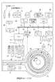
本発明を適用したデジタルカメラ(携帯型電子機器)の正面側及び背面側斜視図を図1及び図2に示す。このデジタルカメラ2のカメラボディ(筐体)3は、図3の上面図に示すように、一方の側方部に位置する円柱形状のグリップ部3aと、他方側に位置する四角柱形状の引き出し通路部3bから形成されている。カメラボディ3の前面には、撮像レンズ10、ストロボ発光窓11が、背面側には、電源ボタン13、決定ボタン14、モードボタン15a,15b、引き込みレバー16、電子式ファインダ(小型画像表示手段)17などが設けられている。電子式ファインダとしては、例えば周知のLCD( 液晶ディスプレイ) が使用される。またグリップ部3aの上面には、レリーズボタン19が設けられている。 1 and 2 are front and rear perspective views of a digital camera (portable electronic device) to which the present invention is applied. As shown in the top view of FIG. 3, the camera body (housing) 3 of the
デジタルカメラ2では、被写体の撮像を行う撮像モード、撮像した記録画像を再生表示する再生モードなどが選択可能となっている。これらのモードの切り替えは、例えば、モードボタン15a,15bを押圧操作することで行われる。 The
さらにカメラボディ3には、グリップ部3aとは反対側に位置する引き出し通路部3bの側面に引き出し口20が形成され、またこの引き出し口20を開閉する引き出し開閉蓋21が設けられている。引き出し開閉蓋21は、引き出し通路部3bに対して開閉自在に取り付けられており、開き位置にあるときには引き出し口20を露呈させ、閉じ位置にあるときには引き出し口20を密閉する。 Further, the
なお、引き出し開閉蓋21の周縁部分には、図3に示すように、引き出し口20と引き出し開閉蓋21との隙間を塞ぐ弾性部材22が設けられている。これによって、引き出し開閉蓋21が閉じ位置にあるとき、引き出し口20と引き出し開閉蓋21との間が密閉され、高い防水性及び防塵性を持つことができる。弾性部材22としては、例えばゴムや軟質樹脂などから形成される。 As shown in FIG. 3, an
さらにカメラボディ3には、グリップ部3aの内部に、電源用の電池26を収納する電池収納室27(図4参照)、及びこの電池収納室27の周囲に位置する表示シート収納室28(図4参照)が設けられている。また、グリップ部3aの背面には、滑り止め用のリブ29aや突起部29bなどが多数形成されている。 Further, the
このデジタルカメラ2には、シート状で柔軟性を持つ画像表示シート30が設けられている。画像表示シート30としては例えば、有機EL(エレクトロルミネッセンス)素子を用いた周知の有機ELシートディスプレイが使用される。この画像表示シート30は、後述するように、再生モード下では、画像を再生するモニタとして、撮像モード下では、撮影画像のスルー画像表示を行うビューファインダとして使用されるものである。 The
さらに、画像表示シート30は、図4に示すように、表示シート収納室28の内部に設けられた巻き軸31の周りに巻き付けられて表示シート収納室28の内部に収納されている。巻き軸31は、電池収納室27の周りに回転自在に取り付けられている。この巻き軸31には、例えばワンウェイクラッチを介して巻き取りモータ32が接続されている。引き込みレバー16を回転操作すると、モータ32が回転駆動してワンウェイクラッチが接続状態となり、モータ32の駆動が巻き軸31に伝達され、巻き取り方向(図中時計方向)に回動する。これにより、画像表示シート30は、巻き軸31に巻き付けられ、表示シート収納室28に引き込まれる。また、画像表示シート30が引き出されるときには、ワンウェイクラッチは解除状態となり、画像表示シート30の引き出しに従動して巻き軸31は引き出し方向( 図中反時計方向) に回動する。なお、画像表示シート30をグリップ部3a内部に巻き取るための駆動源としてはモータ32に限らず、例えば、ねじりコイルバネなどをグリップ部3a内部に組み込み、巻き軸31を巻き取り方向に回転させて画像表示シート30を巻き取るようにしてもよい。 Further, as shown in FIG. 4, the
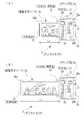
画像表示シート30の使用時には、図5及び図6に示すように、引き出し開閉蓋21を開き位置にし、画像表示シート30をカメラボディ3の外部に引き出す。これによって、画像表示シート30の表示画面30a〜cが露呈する。そして、画像表示シート30の不使用時には、巻き軸31に画像表示シート30を巻き付けて表示シート収納室28の内部に収納し、引き出し開閉蓋21を閉じ位置にする。 When the
この画像表示シート30は、図5に示すように、カメラボディ3の外部に引き出されたとき、その最大長LMAXが、カメラボディ3の横幅(画像表示シート30の引き出し方向における寸法)WBよりも大きくなっている。これにより、本実施形態においては、カメラボディ3の横幅よりも大きなサイズの画像表示手段を配置することが可能となっている。また、画像表示シート30は、その背面側に、複数の表示画面30a〜cが設けられている。本実施形態においては、この表示画面30a〜cの各コマに画像を表示させることができる。なお、本実施形態においては、画像表示シートに3つの表示画面を設けているが、表示画面の個数はこれに限るものではない。As shown in FIG. 5, when the
さらに、画像表示シート30には、その引き出し方向の先端部に、支持部材33が設けられている。支持部材33は、画像表示シート30の引き出し方向に直交する幅方向に沿って配置され、画像表示シート30を支持する。この支持部材33によって、画像表示シート30は平面性を持つことが可能となり、カメラボディ3の外部に画像表示シート30が引き出されたときに、平面性を持った表示画面30a〜cに画像を表示することができる。 Further, the
また、グリップ部3aの底面には、図3の底面図に示すように、電池収納室蓋(グリップ部蓋)36が設けられている。この電池収納室蓋36は、グリップ部3aに対して開閉自在に取り付けられ、開き位置にあるときには電池収納室27を外部に露呈し、閉じ位置にあるときには電池収納室27を密閉する。なお、この電池収納室蓋36にも、上記引き出し開閉蓋21と同様に、その周縁部に隙間を塞ぐための弾性部材37が設けられている。これによって、電池収納室蓋36が閉じ位置にあるときにグリップ部3aの内部を密閉し、高い防水性及び防塵性を持つことができる。なお、この弾性部材37としては、Oリングなどのゴム、又は軟質樹脂などから成形されたものが好ましい。 Further, as shown in the bottom view of FIG. 3, a battery storage chamber lid (grip portion lid) 36 is provided on the bottom surface of the
さらにまた、カメラボディ3には、グリップ部3a及び引き出し通路部3bの稜線に沿って連続するように配置された衝撃吸収部材39が設けられている。衝撃吸収部材39は、断面が円形状のパイプ型に形成されている、カメラボディ3の全体に渡って配置されている。 Furthermore, the
図4は、デジタルカメラ2の電気的構成を示すブロック図である。撮像レンズ10の背後には、CCDイメージセンサやCMOSイメージセンサなどから構成された固体撮像素子41が配置されている。撮像レンズ10を透過した被写体光が、固体撮像素子41によって撮像信号に変換される。固体撮像素子41は、ドライバ42及びタイミングジェネレータ43を介して、デジタルカメラ2の全体を制御するCPU44に接続されている。このCPU44が、ドライバ42及びタイミングジェネレータ43を制御して固体撮像素子41が駆動される。 FIG. 4 is a block diagram showing an electrical configuration of the
この固体撮像素子41から出力された撮像信号は、相関二重サンプリング回路(CDS)45に入力される。CDS45は、固体撮像素子41から入力された撮像信号を、固体撮像素子41の各セルの蓄積電荷量に正確に対応したR、G、Bの画像データとして出力する。CDS45から出力された画像データは、増幅器(AMP)46で増幅される。A/D変換器47は、AMP46で増幅された画像データをデジタルの画像データに変換する。A/D変換器47から出力されたデジタルの画像データは、画像信号処理回路48に送信される。 The imaging signal output from the solid-state imaging device 41 is input to a correlated double sampling circuit (CDS) 45. The CDS 45 outputs the imaging signal input from the solid-state imaging device 41 as R, G, and B image data that accurately corresponds to the accumulated charge amount of each cell of the solid-state imaging device 41. Image data output from the CDS 45 is amplified by an amplifier (AMP) 46. The A /
画像信号処理部48は、データバス49を介してCPU44に接続されている。CPU44は画像信号処理部48を制御して階調変換、ホワイトバランス補正、γ補正処理などの各種画像処理を画像データに施す。さらに画像信号処理部48には、データバス49を介してビデオメモリ50及びバッファメモリ51が接続されている。ビデオメモリ50は、電子式ファインダ17又は画像表示シート30をビューファインダとして使用する際に、画像信号処理部48から送られた解像度の低い画像データが一時的に記録される。ビデオメモリ50に記録された画像データは、データバス49を介してディスプレイドライバ52又は53に送信され、電子式ファインダ17又は画像表示シート30に表示される。バッファメモリ51は、撮像された高解像度のデータが一時的に記録される。このバッファメモリ51から読み出された画像データは、データバス49を解して接続されている圧縮・伸張処理部54により、JPEG等の圧縮方式により圧縮される。圧縮された画像データは、CPU44がメディアコントローラ55を制御してメモリカード56に記録される。 The image
また、CPU44には、モータドライバ58、引き出し量算出部59が接続されている。モータドライバ58は、巻き軸31に接続されたモータ32の回転駆動を制御する。引き出し量算出部59は、巻き軸31に内蔵されたエンコーダ61に接続されている。エンコーダ61は、巻き軸31の回転量を検出して引き出し量算出部59に送り、引き出し量算出部59は巻き軸31の回転量から画像表示シート30の引き出し長さLを算出する。 The
さらにまた、CPU44には、レリーズボタン19、決定ボタン14、モードボタン15a,15b、引き込みレバー16、及び電源ボタン13が接続されている。CPU44は、これらの操作によってユーザーからの指令を取得する。ユーザーから記録画像の再生命令を取得した場合には、CPU44は、メディアコントローラ55を制御してメモリカード56から画像データを読み出す。CPU44は、ディスプレイドライバ52又は53を制御して伸張された画像データに基づく画像を電子式ファインダ17又は画像表示シート30に表示させることができる。 Furthermore, a
このデジタルカメラ2では、電子式ファインダ17又は画像表示シート30のうち、いずれか一方を起動状態、かつ他方を停止状態として、起動状態となっている一方のみを使用して、撮像モード下でのスルー画像表示、及び再生モード下での画像再生表示を行う。この電子式ファインダ17と、画像表示シート30との起動状態・停止状態の切り換えは、画像表示シート30の引き出し操作に連動して行われる。すなわち、画像表示シート30が表示シート収納室28の内部に巻き取られた収納状態のときには、画像表示シート30が停止状態、かつ電子式ファインダ17が起動状態となるようにCPU44がディスプレイドライバ52,53を制御する。そして、画像表示シート30が引き出されたとき、CPU44は、引き出し量算出部59が算出した引き出し量から、画像表示シート30が引き出されていることを検出し、この画像表示シート30の引き出しが検出されたときに、画像表示シート30が起動状態、かつ電子式ファインダ17が停止状態となるようにディスプレイドライバ52,53の制御状態を切り換える。さらに、引き出された画像表示シート30は、引き込みレバー16の操作によってモータ32が駆動されて巻き軸31が巻き取り方向に回転すると、巻き軸31に巻き取られて収納状態となる。このとき、引き出し量算出部59が、画像表示シート30の収納状態(引き出し量が0)であることを検出すると、CPU44は、画像表示シート30を停止状態とし、電子式ファインダ17を起動状態にする。 In this
さらにデジタルカメラ2では、画像表示シート30を引き出した引き出し量Lに応じて表示される画像の個数が変化する。すなわち、図5(A)及び図6(A)に示すように1画面分の引き出し量LMINだけ画像表示シート30を引き出したときには、1つの表示画面30aのみが起動状態となって1つの画像が表示される。そして2画面分の引き出し量となったときには、2つの表示画面30a,30bが起動状態となって2つの画像が表示される。さらに引き出し量が最大のLMAXになったときは、図5(B)及び図6(B)に示すように全ての表示画面30a〜cが起動状態となって、この表示画面30a〜cにそれぞれ画像が表示される。Further, in the
上記構成の作用について図7のフローチャートに基づいて説明する。まず、モードボタン15a,15bの操作によって再生モード、撮像モードのいずれかを選択する。そして、ユーザーは、周囲の撮影環境に応じて画像表示シート30を引き出し状態とするか、それとも収納状態とするかを選択する。このとき、人ごみの中など、画像表示シート30の引き出し操作がしにくいときなどには、収納状態のままとし、室外などで動きやすい場所のときには、引き出し状態とすればよい。 The operation of the above configuration will be described based on the flowchart of FIG. First, either the playback mode or the imaging mode is selected by operating the
そして画像表示シート30を引き出し状態とすると、上述したように画像表示シート30が起動状態となり、電子式ファインダ17が停止状態となる。その後、撮像モードが選択されているときには、画像表示シート30にはスルー画像が表示され、使用者はこれを見ながらフレーミングし、レリーズボタン19を押圧する。レリーズボタン19が押圧されると、メモリカード56に画像データが記憶されて一回の撮像が終了する。なお、再生モードが選択されているときには、メモリカード56に記憶された画像が読み出されて、画像表示シート30に画像が再生表示される。 When the
また、画像表示シート30が収納状態にあるときには、上述したように、電子式ファインダ17が起動状態、かつ画像表示シート30が停止状態となっており、撮像モード下では、電子式ファインダ17に表示されたスルー画像を見ながら撮像を行い、再生モード下では、再生画像が電子式ファインダ17に表示されることになる。 Further, as described above, when the
このようにして、デジタルカメラ2では、画像表示シート30を引き出し状態、又は収納状態として使用することが可能であり、さらに画像表示シート30が収納状態のときには、電子式ファインダ17を使用し、引き出し状態のときには、画像表示シート30を使用するように、制御が切り換えられているので、撮影環境に応じてデジタルカメラ2の使用形態を変化させて使用できるようになっており、さらに画像表示シート30の収納状態ではデジタルカメラ2はコンパクトで携帯性に優れた状態となり、また、引き出し状態では、カメラボディ3よりも大きな画像表示シート30の表示画面に画像を表示できるので、画像が見やすくなり、撮像時のフレーミングや、再生時の画像の確認などに非常に便利である。 In this way, in the
上記実施形態においては、画像表示シート30の引き出し量に応じて画像を表示する表示画面の数が変更するように制御されているが、本発明はこれに限らず、画像表示シート30の引き出し量に応じて画像の表示サイズを変更するようにしてもよい。すなわち、この場合、図8(A)に示す通常の引き出し量L1だけ画像表示シート30を引き出されたときには、通常画面サイズ30dで画像が表示され、さらに画像表示シート30を引き出して、引き出し量がL2(L2>L1)になったときは、横長のワイド画面サイズ30eで画像が表示されるように画像表示シート30の表示内容を切り換える。なお、この場合、例えば通常画面サイズはいわゆるハイビジョンサイズ(アスペクト比が9:16)で、ワイド画面サイズはパノラマサイズ(アスペクト比が1:3)というように設定し、この比率に応じた引き出し長さになったとき、表示を切り換えるようにしてもよい。In the above embodiment, the number of display screens that display an image is controlled to change according to the pull-out amount of the
上記実施形態においては、画像表示シート30の引き出し口20を密閉する部材としてカメラボディ3に開閉自在に取り付けられた引き出し開閉蓋を設けているが、これに限らず、例えばこの開閉蓋の代わりに、柔軟性を持つ弾性材料から形成され、画像表示シート30の不使用時には引き出し口20を遮蔽し、画像表示シート30の使用時には弾性変形して画像表示シート30を引き出し可能とするテレンプのような遮蔽部材を設けてもよい。 In the above-described embodiment, the drawer opening / closing lid attached to the
上記実施形態では、携帯型電子機器としてデジタルカメラを例示して説明したが、本発明はこれに限定されず、他の携帯型電子機器、例えばパーソナルコンピュータや、カメラ付き携帯電話、携帯型情報端末(PDA)、パーソナルAVプレーヤなどにも適用することができる。 In the above embodiment, a digital camera has been described as an example of the portable electronic device. However, the present invention is not limited to this, and other portable electronic devices such as a personal computer, a camera-equipped mobile phone, and a portable information terminal. (PDA), personal AV players, and the like.
2 デジタルカメラ
3 カメラボディ
3a グリップ部
17 電子式ファインダ
30 画像表示シート2
Claims (7)
Translated fromJapanese前記画像表示手段は、シート状で柔軟性を持つ画像表示シートであり、前記筐体は、その一方の側方部に筐体を保持するためのグリップ部が設けられ、さらにこのグリップ部の内部に、前記電池を入れる電池収納室、及び電池収納室の周囲に前記画像表示シートを巻き付けた状態で収納する表示シート収納室が設けられており、前記画像表示シートの使用時には、前記筐体から前記画像表示シートを引き出して使用することを特徴とする携帯型電子機器。In a portable electronic device comprising an image display means for displaying an image based on image data read from a storage medium, a battery serving as a power source, and a housing supporting these,
The image display means is a sheet-like and flexible image display sheet, and the housing is provided with a grip portion for holding the housing on one side portion thereof, and the inside of the grip portion is further provided. A battery storage chamber for storing the battery, and a display sheet storage chamber for storing the image display sheet around the battery storage chamber, and when the image display sheet is used, A portable electronic device, wherein the image display sheet is pulled out and used.
Priority Applications (2)
| Application Number | Priority Date | Filing Date | Title |
|---|---|---|---|
| JP2004091882AJP2005278058A (en) | 2004-03-26 | 2004-03-26 | Portable electronic apparatus |
| US11/088,914US20050212942A1 (en) | 2004-03-26 | 2005-03-25 | Portable electronics device for displaying an image on a sheet-shaped image display |
Applications Claiming Priority (1)
| Application Number | Priority Date | Filing Date | Title |
|---|---|---|---|
| JP2004091882AJP2005278058A (en) | 2004-03-26 | 2004-03-26 | Portable electronic apparatus |
Publications (1)
| Publication Number | Publication Date |
|---|---|
| JP2005278058Atrue JP2005278058A (en) | 2005-10-06 |
Family
ID=34989324
Family Applications (1)
| Application Number | Title | Priority Date | Filing Date |
|---|---|---|---|
| JP2004091882APendingJP2005278058A (en) | 2004-03-26 | 2004-03-26 | Portable electronic apparatus |
Country Status (2)
| Country | Link |
|---|---|
| US (1) | US20050212942A1 (en) |
| JP (1) | JP2005278058A (en) |
Cited By (6)
| Publication number | Priority date | Publication date | Assignee | Title |
|---|---|---|---|---|
| JP2011114509A (en)* | 2009-11-26 | 2011-06-09 | Nikon Corp | Display device and image pickup device |
| JP2013037330A (en)* | 2011-08-10 | 2013-02-21 | Samsung Display Co Ltd | Display device |
| JP2013232214A (en)* | 2007-03-06 | 2013-11-14 | Creator Technology Bv | Display device, display method and computer program product |
| WO2014171179A1 (en)* | 2013-04-19 | 2014-10-23 | ソニー株式会社 | Information processing device, information processing method, and imaging device |
| KR101517179B1 (en) | 2012-11-22 | 2015-05-04 | 임유섭 | Flexible display apparatus with the torque generating method of roller by the folding or unfolding operation power |
| KR101591075B1 (en) | 2014-12-29 | 2016-02-02 | 임유섭 | Flexible display apparatus with the torque generating method of roller by the folding or unfolding operation power |
Families Citing this family (9)
| Publication number | Priority date | Publication date | Assignee | Title |
|---|---|---|---|---|
| JP2007081556A (en)* | 2005-09-12 | 2007-03-29 | Canon Inc | Imaging apparatus and control method thereof |
| JP4977363B2 (en) | 2005-12-09 | 2012-07-18 | 富士フイルム株式会社 | Display device |
| US20080231740A1 (en)* | 2007-03-21 | 2008-09-25 | Mcintyre Dale F | Camera with multiple displays |
| US20080231741A1 (en)* | 2007-03-21 | 2008-09-25 | Mcintyre Dale F | Camera with multiple displays |
| US20080245453A1 (en)* | 2007-04-03 | 2008-10-09 | David Law | Battery Grip Protective Device for Cameras, Video Recorders, and Other Electronic Devices |
| US20080245452A1 (en)* | 2007-04-03 | 2008-10-09 | David Law | Weatherproofing Apparatus and Method for Cameras and Video Recorders |
| US9182935B2 (en) | 2011-09-27 | 2015-11-10 | Z124 | Secondary single screen mode activation through menu option |
| KR102319684B1 (en)* | 2015-06-22 | 2021-11-02 | 엘지전자 주식회사 | Deformable display device and operating method thereof |
| KR20170036489A (en)* | 2015-09-24 | 2017-04-03 | 엘지전자 주식회사 | Camera module and mobile terminal communicatively therewith |
Family Cites Families (14)
| Publication number | Priority date | Publication date | Assignee | Title |
|---|---|---|---|---|
| MX9305144A (en)* | 1992-08-31 | 1994-03-31 | Motorola Inc | PIVOTABLE OR ROTABLE DISPLAY HEAD FOR AN ELECTRONIC DEVICE. |
| FI103238B1 (en)* | 1997-02-21 | 1999-05-14 | Nokia Mobile Phones Ltd | Mobile communication devices |
| US6643124B1 (en)* | 2000-08-09 | 2003-11-04 | Peter J. Wilk | Multiple display portable computing devices |
| US6640113B1 (en)* | 2000-09-08 | 2003-10-28 | Mobigence, Inc. | Touch sensitive display integrated with a handheld radiotelephone |
| US20020090980A1 (en)* | 2000-12-05 | 2002-07-11 | Wilcox Russell J. | Displays for portable electronic apparatus |
| JP2002209226A (en)* | 2000-12-28 | 2002-07-26 | Canon Inc | Imaging device |
| US20030050019A1 (en)* | 2001-09-07 | 2003-03-13 | Dowling Eric Morgan | Mobile units with fexible-retractable peripherals |
| US6940497B2 (en)* | 2001-10-16 | 2005-09-06 | Hewlett-Packard Development Company, L.P. | Portable electronic reading apparatus |
| US7050835B2 (en)* | 2001-12-12 | 2006-05-23 | Universal Display Corporation | Intelligent multi-media display communication system |
| US7184086B2 (en)* | 2002-02-25 | 2007-02-27 | Konica Corporation | Camera having flexible display |
| JP2003316563A (en)* | 2002-04-22 | 2003-11-07 | Pioneer Electronic Corp | Information terminal, method for controlling information terminal and display control program |
| JP3722125B2 (en)* | 2003-01-30 | 2005-11-30 | コニカミノルタフォトイメージング株式会社 | Imaging device |
| JP2005130045A (en)* | 2003-10-21 | 2005-05-19 | Konica Minolta Photo Imaging Inc | Image pickup apparatus and image pickup element used therefor |
| US20050088463A1 (en)* | 2003-10-23 | 2005-04-28 | Schilling Donald L. | Expanded display for cell phone, palm pilot or computer |
- 2004
- 2004-03-26JPJP2004091882Apatent/JP2005278058A/enactivePending
- 2005
- 2005-03-25USUS11/088,914patent/US20050212942A1/ennot_activeAbandoned
Cited By (9)
| Publication number | Priority date | Publication date | Assignee | Title |
|---|---|---|---|---|
| JP2013232214A (en)* | 2007-03-06 | 2013-11-14 | Creator Technology Bv | Display device, display method and computer program product |
| JP2011114509A (en)* | 2009-11-26 | 2011-06-09 | Nikon Corp | Display device and image pickup device |
| JP2013037330A (en)* | 2011-08-10 | 2013-02-21 | Samsung Display Co Ltd | Display device |
| US9230468B2 (en) | 2011-08-10 | 2016-01-05 | Samsung Display Co., Ltd. | Display device |
| KR101517179B1 (en) | 2012-11-22 | 2015-05-04 | 임유섭 | Flexible display apparatus with the torque generating method of roller by the folding or unfolding operation power |
| WO2014171179A1 (en)* | 2013-04-19 | 2014-10-23 | ソニー株式会社 | Information processing device, information processing method, and imaging device |
| JPWO2014171179A1 (en)* | 2013-04-19 | 2017-02-16 | ソニー株式会社 | Information processing apparatus, information processing method, and imaging apparatus |
| US10051188B2 (en) | 2013-04-19 | 2018-08-14 | Sony Corporation | Information processing device and image shooting device for display of information on flexible display |
| KR101591075B1 (en) | 2014-12-29 | 2016-02-02 | 임유섭 | Flexible display apparatus with the torque generating method of roller by the folding or unfolding operation power |
Also Published As
| Publication number | Publication date |
|---|---|
| US20050212942A1 (en) | 2005-09-29 |
Similar Documents
| Publication | Publication Date | Title |
|---|---|---|
| US7009637B2 (en) | Portable multi-function apparatus and controller | |
| JP4657977B2 (en) | Imaging device | |
| CN100550982C (en) | Image Quality Selection Method and Digital Camera | |
| JP2005278058A (en) | Portable electronic apparatus | |
| JP4431447B2 (en) | Digital camera | |
| US6683644B1 (en) | Portable electronic apparatus with flat display | |
| KR20090045117A (en) | Portable and Imaging Devices | |
| JP2008011232A (en) | Digital camera | |
| JP2005236883A (en) | Photographing apparatus | |
| JP4732387B2 (en) | Display device, display control method thereof, and imaging device | |
| JP2006060585A (en) | Digital camera | |
| JPH11298773A (en) | Camera with monitor | |
| JP4565265B2 (en) | Electronic camera with projector and electronic camera system | |
| JP4110268B2 (en) | camera | |
| JP4581780B2 (en) | Display device with touch panel | |
| US20060215051A1 (en) | Display device | |
| JP4338456B2 (en) | Digital camera | |
| JP4570837B2 (en) | Imaging device | |
| US7982780B2 (en) | Photographing apparatus having multiple control button sets and displays and method of displaying image | |
| EP1437732A1 (en) | Portable Digital Video Recorder | |
| JP4184166B2 (en) | Audio recording / playback device | |
| JP2003005266A (en) | Camera | |
| JP4507278B2 (en) | Display device with switch panel | |
| JP4485391B2 (en) | Camera, camera system and electronic device | |
| JP2004194102A (en) | Digital camera |
Legal Events
| Date | Code | Title | Description |
|---|---|---|---|
| A621 | Written request for application examination | Free format text:JAPANESE INTERMEDIATE CODE: A621 Effective date:20060519 | |
| A711 | Notification of change in applicant | Free format text:JAPANESE INTERMEDIATE CODE: A712 Effective date:20061221 | |
| A977 | Report on retrieval | Free format text:JAPANESE INTERMEDIATE CODE: A971007 Effective date:20081211 | |
| A131 | Notification of reasons for refusal | Free format text:JAPANESE INTERMEDIATE CODE: A131 Effective date:20081224 | |
| A521 | Request for written amendment filed | Free format text:JAPANESE INTERMEDIATE CODE: A523 Effective date:20090218 | |
| A02 | Decision of refusal | Free format text:JAPANESE INTERMEDIATE CODE: A02 Effective date:20090408 |