JP2005277937A - Communication method and communication apparatus - Google Patents
Communication method and communication apparatusDownload PDFInfo
- Publication number
- JP2005277937A JP2005277937AJP2004090061AJP2004090061AJP2005277937AJP 2005277937 AJP2005277937 AJP 2005277937AJP 2004090061 AJP2004090061 AJP 2004090061AJP 2004090061 AJP2004090061 AJP 2004090061AJP 2005277937 AJP2005277937 AJP 2005277937A
- Authority
- JP
- Japan
- Prior art keywords
- address
- communication
- communication terminal
- address assignment
- information
- Prior art date
- Legal status (The legal status is an assumption and is not a legal conclusion. Google has not performed a legal analysis and makes no representation as to the accuracy of the status listed.)
- Withdrawn
Links
Images


Landscapes
- Small-Scale Networks (AREA)
- Mobile Radio Communication Systems (AREA)
Abstract
Description
Translated fromJapanese本発明は、ネットワークにおける通信方法に関し、例えば無線通信により画像等のデータを送信するのに先立ち、通信に用いるアドレス情報を自動的に重複しないように割り当てる技術に関する。 The present invention relates to a communication method in a network, for example, to a technique for automatically assigning address information used for communication so as not to overlap before transmitting data such as an image by wireless communication.
従来、通信に用いるアドレス情報を重複しないように自動的に決定する代表的な方法として、DHCP(Dynamic Host Configuration Protocol)とAuto-IP(Auto Internet Protocol)との2種類の方法が実現されている。 2. Description of the Related Art Conventionally, two types of methods, DHCP (Dynamic Host Configuration Protocol) and Auto-IP (Auto Internet Protocol), have been realized as typical methods for automatically determining address information used for communication so as not to overlap. .
DHCPによる方法では、通信を行う各通信端末に対し、アドレス情報を配布及び管理するサーバ機能を有する通信端末を設置する。ここで、このサーバ機能を有する通信端末からアドレスを取得し、通信を行う各通信端末は「DHCPクライアント」と呼ばれ、このサーバ機能を有する通信端末は「DHCPサーバ」と呼ばれる。各DHCPクライアントは、データ通信を行う前にアドレス情報をDHCPサーバから取得する。そのアドレス情報を取得する手順は、以下のようになる。
(1)DHCPクライアントがDHCP発見パケットをブロードキャストし、IPアドレス、ネットマスク等のネットワークの設定を要求する。
(2)DHCPサーバがDHCP発見パケットに応答し、DHCP提供パケットをDHCPクライアントに送信し、使用してよいネットワークの設定を通知する。
(3)DHCPクライアントがDHCP要求パケットをブロードキャストし、通知されたネットワークの設定を使用したいことを通知する。
(4)DHCPサーバがDHCP確認応答パケットをDHCPクライアントに送信し、そのDHCP要求で通知された要求の許可又は不許可を通知する。In the DHCP method, a communication terminal having a server function for distributing and managing address information is installed for each communication terminal that performs communication. Here, each communication terminal that obtains an address from the communication terminal having the server function and performs communication is called a “DHCP client”, and the communication terminal having the server function is called a “DHCP server”. Each DHCP client acquires address information from a DHCP server before performing data communication. The procedure for acquiring the address information is as follows.
(1) A DHCP client broadcasts a DHCP discovery packet and requests network settings such as an IP address and a netmask.
(2) The DHCP server responds to the DHCP discovery packet, sends a DHCP provided packet to the DHCP client, and notifies the network settings that can be used.
(3) The DHCP client broadcasts a DHCP request packet to notify that it is desired to use the notified network setting.
(4) The DHCP server transmits a DHCP confirmation response packet to the DHCP client, and notifies whether the request notified by the DHCP request is permitted or not.
また、DHCPによるアドレス情報の取得を発展させた方法として、主DHCPサーバの他に副DHCPサーバを有し、主・副DHCPサーバの間で割り当てテーブルを共有し、主DHCPサーバに障害があった場合、副DHCPサーバが代行する方法(例えば、特許文献1参照)、DHCPサーバの他に管理サーバを有し、異なるネットワーク間を移動した端末について、論理アドレスを流用するための方法(例えば、特許文献2参照)、DHCPサーバが自己のホスト名と、アドレス割当要求を送信したクライアントのアドレス割当を担当するホスト名が一致した時にのみ応答することにより、特定DHCPサーバのみが応答することを実現した方法(例えば、特許文献3参照)などが提案されている。 In addition, as a method of developing acquisition of address information by DHCP, there is a secondary DHCP server in addition to the primary DHCP server, and the allocation table is shared between the primary and secondary DHCP servers, and the primary DHCP server has a failure. In this case, a method in which a secondary DHCP server acts as a proxy (for example, see Patent Document 1), a method for diverting a logical address to a terminal that has a management server in addition to a DHCP server and moves between different networks (for example, a patent) (Refer to Reference 2), the DHCP server responds only when the host name of its own and the host name in charge of address assignment of the client that sent the address assignment request match, thereby realizing that only the specific DHCP server responds A method (see, for example, Patent Document 3) has been proposed.
一方、Auto-IPによる方法では、通信を行う複数の通信端末が所定のアドレス範囲からアドレス情報を選択する。各通信端末は、選択したアドレス情報に対して、ARP(Address Resolution Protocol)要求パケットを送信する。各通信端末は、送信したARP要求パケットに対し、ARP応答パケットが受信された場合、その選択したアドレス情報を破棄し、新たなアドレス情報を選択し、新たに選択したアドレス情報に対して、ARP要求パケットの送信を行う。送信したARP要求パケットに対して、所定のタイムアウト時間内にARP応答パケットが受信できなかった場合、送信したアドレス情報を各通信端末のアドレス情報として決定する。 On the other hand, in the method using Auto-IP, a plurality of communication terminals that perform communication select address information from a predetermined address range. Each communication terminal transmits an ARP (Address Resolution Protocol) request packet for the selected address information. When an ARP response packet is received for each transmitted ARP request packet, each communication terminal discards the selected address information, selects new address information, and selects the ARP for the newly selected address information. Send a request packet. If the ARP response packet is not received within a predetermined timeout period for the transmitted ARP request packet, the transmitted address information is determined as the address information of each communication terminal.
次に、本発明を適用可能な無線ネットワーク規格の代表的なものとして、IEEE802.11と呼ばれる規格がある。IEEE802.11のネットワーク形成方法について説明する。 Next, as a representative wireless network standard to which the present invention can be applied, there is a standard called IEEE802.11. An IEEE 802.11 network formation method will be described.
IEEE802.11で規定されているネットワークには、集中制御局のある「インフラストラクチャーモード」と、集中制御局のない「アドホックモード」とがある。IEEE802.11では、チャネルと呼ばれる通信に用いられる周波数帯が複数規定されている。このネットワークに参加する各通信端末は、複数のチャネルのうち一を選択し、選択したチャネルを用いて通信を行う。また、「ESS-ID(Extended Service Set Identifier)」と呼ばれるネットワークを識別する識別子が規定されている。各通信端末は、ESS-IDを保持しており、同一のESS-IDを有するネットワークに接続する。 Networks defined by IEEE802.11 have an “infrastructure mode” with a central control station and an “ad hoc mode” without a central control station. IEEE802.11 defines a plurality of frequency bands used for communication called channels. Each communication terminal participating in the network selects one of a plurality of channels and performs communication using the selected channel. Also, an identifier for identifying a network called “ESS-ID (Extended Service Set Identifier)” is defined. Each communication terminal holds an ESS-ID and connects to a network having the same ESS-ID.
インフラストラクチャーモードにおいては、集中制御局であるアクセスポイントが制御するネットワークを識別するESS-IDを保持している。アクセスポイントはそのESS-IDを含むビーコンを定期的にブロードキャストしている。また、インフラストラクチャーモードのネットワークに参加する通信端末であるステーションでも自己が参加するネットワークを識別するESS-IDを有している。ここで、ステーションは複数のチャネルを順次切り替え、各チャネル上でビーコンを受信し、そのビーコンに含まれるESS-IDを取得する。そして、取得したESS-IDと保有しているESS-IDとが一致した場合、そのビーコンを受信したチャネルを通信に用いるチャネルとして選択し、そのビーコンを送信したアクセスポイントと接続処理を行う。 In the infrastructure mode, an ESS-ID for identifying a network controlled by an access point that is a central control station is held. The access point periodically broadcasts a beacon including the ESS-ID. In addition, even a station that is a communication terminal participating in an infrastructure mode network has an ESS-ID that identifies the network in which the station participates. Here, the station sequentially switches a plurality of channels, receives a beacon on each channel, and acquires an ESS-ID included in the beacon. When the acquired ESS-ID matches the ESS-ID possessed, the channel that received the beacon is selected as the channel used for communication, and connection processing is performed with the access point that transmitted the beacon.
一方、アドホックモードのネットワークに参加する通信端末であるステーションも自己が参加するネットワークを識別するSSID(Service Set Identifier)を有している。このアドホックモードにおいては、ネットワークに参加している各ステーションが所定の順番でビーコンを送信している。新たにネットワークに参加するステーションは、複数のチャネルを順次切り替え、各チャネル上でビーコンを受信し、そのビーコンに含まれるSSIDを取得する。そして、受信したSSIDと保有しているSSIDとが一致した場合、そのビーコンを受信したチャネルを通信に用いるチャネルとして選択する。 On the other hand, a station, which is a communication terminal participating in an ad hoc mode network, also has an SSID (Service Set Identifier) that identifies the network in which it is participating. In this ad hoc mode, each station participating in the network transmits a beacon in a predetermined order. A station newly joining the network sequentially switches a plurality of channels, receives a beacon on each channel, and acquires an SSID included in the beacon. If the received SSID and the owned SSID match, the channel that received the beacon is selected as the channel used for communication.
図8は、従来の無線通信システムにおける通信フレームの一例を示す図である。図8に示す通信フレームの宛先MACアドレス801、送信元MACアドレス802及びネットワークタイプ803は、イーサネット(登録商標)プロトコルなどの所定のプロトコルに従って生成される。宛先MACアドレス801及び送信元MACアドレス802は、それぞれ、現在直接の宛先、送信元となる機器を識別するための、それぞれの機器に固定的に割り当てられる数値列である。また、ネットワークタイプ803は、ネットワークタイプ803以降の通信フレームの構成を指定するものである。 FIG. 8 is a diagram illustrating an example of a communication frame in a conventional wireless communication system. The
また、宛先IPアドレス804、送信元IPアドレス805、フレーム制御情報806がIPプロトコル等のプロトコルに従って生成される。ここで宛先IPアドレス805、送信元IPアドレス806は、最終的な送信元、宛先となる機器を識別するための論理的な数値列である。また、フレーム制御情報806は、通信フレームの重複や、抜けなどを検査し、更に複数フレームに分解されたフレームを再構成するためなどに用いられる情報である。そして、データ807は、通信フレームで送信する情報である。 Also, a
上述した各プロトコル及びフレーム構成については、非特許文献1に詳しく説明されている。
無線通信機能を有するプリンタなどの印字装置と無線通信機能を有するデジタルカメラなどの撮像装置との間で、上述したIEEE802.11準拠の無線ネットワークにおいて、通信を行い、上述の撮像装置で撮影した画像データを上述の印字装置から出力する場合、通信に用いるSSID、チャネル、アドレス情報など多くの情報を上述した印字装置及び撮像装置に入力し、設定を行う必要があった。しかし、このような無線通信機能付きの印字装置及び撮像装置にはユーザインターフェースが乏しく、設定を行うことは容易でなかった。 An image captured by the above-described imaging device by performing communication between a printing device such as a printer having a wireless communication function and an imaging device such as a digital camera having a wireless communication function in the above-described IEEE 802.11-compliant wireless network. When data is output from the above-described printing apparatus, it is necessary to input and set a lot of information such as SSID, channel, and address information used for communication to the above-described printing apparatus and imaging apparatus. However, such a printing apparatus and an imaging apparatus with a wireless communication function have a poor user interface, and it is not easy to make settings.
そこで、上述したDHCP、Auto-IP等を採用し、アドレス情報の入力を省く試みが行われている。上述したDHCPを用いる場合、様々な方法が提案されているが、別途DHCPサーバを設ける必要がある。インフラストラクチャーモードを使用する際には、アクセスポイントがDHCPサーバ機能を有することができるが、特にアドホックモードにおいては、別途DHCPサーバを準備する必要があった。 Therefore, attempts have been made to adopt the above-described DHCP, Auto-IP, etc., and to omit input of address information. When using the DHCP described above, various methods have been proposed, but it is necessary to provide a separate DHCP server. When using the infrastructure mode, the access point can have a DHCP server function. However, in the ad hoc mode, it is necessary to prepare a separate DHCP server.
また、Auto-IPを利用する場合、所定のタイムアウト時間の間、待つ必要があり、撮影データを送信する前の、初期化処理に多くの時間を費やす必要があった。更に、ユーザによる撮像装置に対するSSIDの設定を省き、各チャネルにおいて通信相手となる印字装置を探す手続きを実現した場合において、各チャネルにおいてアドレス情報を取得する必要がある場合も多く、より多くの初期化処理時間が必要となっていた。 Further, when using Auto-IP, it is necessary to wait for a predetermined time-out period, and it is necessary to spend a lot of time for initialization processing before transmission of imaging data. In addition, when the procedure for searching for a printing device to be a communication partner in each channel is realized by omitting the SSID setting for the imaging device by the user, it is often necessary to acquire address information in each channel. Processing time was required.
本発明は、上記課題を解決するためになされたもので、DHCPサーバを別途静的に設けることなく、Auto-IPのアドレス割り当て毎にタイムアウト時間を待つ必要もないアドレス割り当て方法を提供することを目的とする。 The present invention has been made to solve the above-described problem, and provides an address assignment method that does not need to wait for a time-out period for each Auto-IP address assignment without separately providing a DHCP server. Objective.
本発明は、複数の通信端末を物理的に識別する物理的アドレスと、複数の通信端末を論理的に識別する論理的アドレスとを用いて通信する通信ネットワークのアドレス割り当て方法であって、物理的アドレスに対して論理的アドレスを割り当てるアドレス割り当て工程と、他の通信端末で割り当てられた論理的アドレスを取得するアドレス取得工程と、前記アドレス割り当て工程か、アドレス取得工程の何れかを有効とする切り替え工程とを有することを特徴とする。 The present invention relates to an address assignment method for a communication network that performs communication using a physical address that physically identifies a plurality of communication terminals and a logical address that logically identifies the plurality of communication terminals. An address assignment step of assigning a logical address to the address, an address acquisition step of obtaining a logical address assigned by another communication terminal, and a switching to enable either the address assignment step or the address acquisition step And a process.
本発明によれば、周囲の通信端末の状況にあったアドレス割り当てを行うことができる。 ADVANTAGE OF THE INVENTION According to this invention, the address allocation suitable for the condition of the surrounding communication terminal can be performed.
また、無線通信に参加する各無線端末にDHCPサーバ機能を搭載し、通信開始時の初期化処理において、各無線端末のデバイス種別、起動順、ネットワークへの参加順等、所定の優先順位に従って、DHCPサーバ機能を起動するか否かを決定し、各無線端末に割り当てたアドレス情報を管理するアドレス管理テーブルを各無線端末間で共有することにより、DHCPサーバを起動している無線端末がネットワークを抜けた際に、他の無線端末が遅滞無くDHCPサーバ機能を立ち上げ、アドレス割り当てを連続的に行うことができる。 In addition, each wireless terminal participating in wireless communication is equipped with a DHCP server function, and in the initialization process at the start of communication, according to a predetermined priority order, such as the device type of each wireless terminal, the startup order, the order of participation in the network, By deciding whether or not to activate the DHCP server function and sharing the address management table for managing the address information assigned to each wireless terminal, the wireless terminal that activates the DHCP server When leaving, other wireless terminals can start up the DHCP server function without delay and perform address assignment continuously.
以下、図面を参照しながら発明を実施するための最良の形態について詳細に説明する。 The best mode for carrying out the invention will be described below in detail with reference to the drawings.
図1は、本実施形態における無線ネットワークの一例を示す模式図である。図1に示すように、ネットワークには、無線通信機能を有するデジタルカメラである無線通信機能付撮像装置101、無線通信機能を有するプリンタである無線通信機能付印字装置102、第2の無線通信機能付撮像装置103、第2の無線通信機能付印字装置104、無線通信機能を有するハードディスク等の磁気記録装置や無線通信機能を有するDVD(Digital Versatile Disk)等の光記憶装置である無線通信機能付記録装置105、パーソナルコンピュータやPDA(Personal Digital Assistance)等である無線通信機能付端末106等が接続される。 FIG. 1 is a schematic diagram illustrating an example of a wireless network according to the present embodiment. As shown in FIG. 1, the network includes an
尚、本実施形態では、無線方式として、無線LANの物理層及びメディアアクセス制御層(MAC層)を標準化しているIEEE802.11を例に説明する。 In the present embodiment, an example of IEEE802.11 that standardizes the physical layer and the media access control layer (MAC layer) of the wireless LAN will be described as an example of the wireless method.
ここで、無線通信機能付撮像装置101で撮影された画像は、無線通信機能付印字装置102又は第2の無線通信機能付印字装置104に送信されて印刷されたり、無線通信機能付記憶装置105に送信されて記憶されたり、無線通信機能付端末106に送信されて編集、記録又は閲覧されたり、第2の無線通信機能付撮像装置103に送信されて記憶、閲覧されたりする。また、無線通信機能付記憶装置105に記憶されている画像又は無線通信機能付端末106で編集或いは記憶されている画像も同様に、無線通信機能付印字装置102又は無線通信機能付印字装置104に送信された印刷されたり、無線通信機能付記憶装置105に送信されて記憶されたり、無線通信機能付端末106に送信されて編集、記録又は閲覧されたり、無線通信機能付撮像装置101或いは無線通信機能付撮像装置103に送信されて記憶、閲覧されたりする。 Here, the image photographed by the
図2は、本実施形態における無線通信機能付撮像装置の構成の一例を示すブロック図である。本実施形態では、図1に示した無線通信機能付撮像装置101及び無線通信機能付撮像装置103に適用可能なデジタルカメラを例に説明する。 FIG. 2 is a block diagram illustrating an example of the configuration of the imaging apparatus with a wireless communication function in the present embodiment. In the present embodiment, a digital camera applicable to the
図2に示すデジタルカメラの画像入力部201は、光学系によって画像を撮影し、撮影された画像信号をビット情報に変換しデジタル画像として入力する。入力されたデジタル画像は後述する記録部202に記憶されたり、後述する無線通信部203から送信されたりする。記録部202は、メモリカード及びメモリカードの制御装置等で構成され、画像入力部201から入力された画像を記録する。無線通信部203は、所定のプロトコルに従って画像を無線通信により送受信する。ユーザインターフェース(I/F)部204は、ユーザが画像撮影、送信、電源オン/オフ等の指示を入力するためのキーや各種状態を表示するLCD表示器等で構成される。制御部205は、各装置を協調制御する中央処理装置等である。また、デジタルカメラを構成する各機能部はバスなどで結合され、相互にデータ交換及び/又は制御可能である。 An
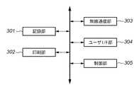
図3は、本実施形態における無線通信機能付印字装置の構成の一例を示すブロック図である。本実施形態では、図1に示した無線通信機能付印字装置102に適用可能なプリンタを例に説明する。 FIG. 3 is a block diagram showing an example of the configuration of the printing apparatus with a wireless communication function in the present embodiment. In the present embodiment, a printer that can be applied to the
図3に示すプリンタの記録部301は、後述する無線通信部303が受信したデータ等を記憶する。印刷部302は、記録部301に記憶されたデータを印刷可能な形式に展開し、紙などの外部媒体に印刷する。無線通信部303は、所定のプロトコルに従ってデータを受信し、記録部301に記憶する。ユーザインターフェース(I/F)部204は、ユーザが各種設定、電源オン/オフ等の指示を入力するためのキーや各種状態を表示するLCD表示器等で構成される。制御部305は、各装置を協調制御する中央処理装置等である。また、プリンタを構成する各機能部はバスなどで結合され、相互にデータ交換及び/又は制御可能である。 The
以上の構成からなるIEEE802.11準拠の無線通信システムにおいて、複数の無線通信機能付通信端末が無線通信に用いるSSID、チャネル、アドレス情報を決定する方法について説明する。 A method of determining SSID, channel, and address information used by a plurality of communication terminals with a wireless communication function in a wireless communication system compliant with IEEE802.11 having the above configuration will be described.
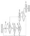
図4は、通信端末の起動時における接続・アドレス割り当て処理を表すフローチャートである。この処理は、図2に示した無線通信機能付撮像装置や図3に示した無線通信機能付印字装置で実行されるものである。 FIG. 4 is a flowchart showing a connection / address assignment process when the communication terminal is activated. This process is executed by the imaging apparatus with a wireless communication function shown in FIG. 2 or the printing apparatus with a wireless communication function shown in FIG.
また、図4に示す処理は、例えば無線通信機能付撮像装置101が撮影した画像を無線通信機能付印字装置102に送信して印刷させる無線印字システムにおけるネットワーク接続及びアドレス割り当て処理に適用可能であり、特に無線通信機能付撮像装置101にはSSIDやチャネルを設定せずに、無線通信機能付印字装置102にのみ、SSIDとチャネルとを設定し、無線通信機能付撮像装置101がネットワークに接続する際に、通信相手を検索してアドレスを割り当てる処理である。 4 is applicable to, for example, network connection and address assignment processing in a wireless printing system in which an image captured by the imaging device with
尚、この適用事例は一例であり、これに限定するものではなく、他の通信システムにも容易に適用可能である。図4に示すフローチャートは、インフラストラクチャーモードとアドホックモードの何れにも適用可能であるが、ここではアドホックモードについて説明する。 In addition, this application example is an example, it is not limited to this, It can apply easily to another communication system. The flowchart shown in FIG. 4 can be applied to both the infrastructure mode and the ad hoc mode. Here, the ad hoc mode will be described.
まず、無線通信機能付撮像装置101と無線通信機能付印字装置102が起動されると、ステップS401において、SSIDの一覧を保持していない場合、全チャネルでビーコンの受信を行い、受信されたビーコンに含まれているSSIDの一覧を生成する。SSIDの一覧にはSSIDと各SSIDに対応付けられたフラグ情報が記録される。このフラグ情報は、後述するステップS402で接続相手デバイスの検索を試みていないSSIDを判別するために用いられる。そして、そのSSIDの一覧の中から、接続相手デバイスの検索を試みていないSSIDを選択し、そのSSIDで表されるネットワークに接続する。一例として、フラグ情報がセットされていないSSIDを選択する。選択され、接続されたネットワークを示すSSIDに対応するフラグ情報がセットされる。 First, when the imaging device with
次に、ステップS402において、所望のサービスを提供している通信端末を検索する。一例として、所望のサービス名称をフレーム内に含むサービス検索フレームをブロードキャストし、そのサービスを提供している通信端末がそのサービス検索フレームを受信すると、そのサービス検索フレームの送信元に対して、自己がそのサービスを提供していることを表す情報を含む、サービス応答フレームを送信し応答する。 Next, in step S402, a communication terminal that provides a desired service is searched. As an example, when a service search frame that includes a desired service name in a frame is broadcast and a communication terminal that provides the service receives the service search frame, A service response frame including information indicating that the service is provided is transmitted and responded.
次に、ステップS403において、サービス応答フレームが受信された場合はステップS404へ進み、現在のSSID、チャネルを実際にデータ通信に用いるSSID、チャネルとして決定する。そして、ステップS405において、アドレス取得機能であるDHCPクライアントを起動し、既にネットワーク上に起動されている、アドレス割り当て機能であるDHCPサーバからアドレスを取得する。尚、アドレス取得の具体的なシーケンスは、従来の技術で説明した方法によるものとする。 Next, when a service response frame is received in step S403, the process proceeds to step S404, and the current SSID and channel are determined as the SSID and channel actually used for data communication. In step S405, a DHCP client that is an address acquisition function is activated, and an address is acquired from a DHCP server that is already activated on the network and is an address assignment function. It should be noted that the specific sequence of address acquisition is based on the method described in the prior art.
また、ステップS403で、サービス応答フレームが受信されなかった場合はステップS406へ進み、ステップS401で作成したSSIDの一覧に、ステップS402での接続相手デバイスの検索を試みていないSSIDが残っているか否かを調べる。具体的には、一例として、フラグ情報がセットされていないSSIDが残っているか否かを調べる。ここで接続相手デバイスの検索を試みていないSSIDが残っている場合にはステップS401に戻るが、残っていない場合にはステップS407へ進み、新たなネットワークを形成するか否かを決定する。 If a service response frame is not received in step S403, the process proceeds to step S406, and whether or not an SSID that has not been searched for a connection partner device in step S402 remains in the list of SSIDs created in step S401. Find out. Specifically, as an example, it is checked whether or not there remains an SSID for which flag information is not set. If an SSID that has not been searched for a connection partner device remains, the process returns to step S401. If no SSID remains, the process proceeds to step S407 to determine whether or not to form a new network.
ここで、新たなネットワークを形成する場合にはステップS408へ進み、所定の方法により通信に用いるSSIDとチャネルを決定し、ネットワークを構築、ビーコンのブロードキャストを開始する。そして、ステップS409において、自己のIPアドレスを所定の値に決定する。次に、ステップS410において、アドレス割り当て機能であるDHCPサーバ機能を起動し、DHCPサーバを起動したことを示すサーバ通知情報を含むサーバ通知フレームを送信する。 If a new network is to be formed, the process proceeds to step S408, the SSID and channel used for communication are determined by a predetermined method, the network is constructed, and beacon broadcasting is started. In step S409, the self IP address is determined to be a predetermined value. Next, in step S410, the DHCP server function which is an address assignment function is activated, and a server notification frame including server notification information indicating that the DHCP server has been activated is transmitted.
尚、新たなネットワークを形成するか否か、SSID、チャネル、及び自己のIPアドレス、DHCPサーバ機能により割り当てるIPアドレスの範囲などは、処理の都度、ユーザインターフェースより入力しても良いし、予めユーザ又は装置の製造者などが設定しておいても良い。 Whether or not to form a new network, SSID, channel, own IP address, range of IP addresses assigned by the DHCP server function, etc. may be input from the user interface every time processing is performed. Alternatively, it may be set by the manufacturer of the apparatus.
図5は、図1に示した無線通信システムに適用可能な接続・アドレス割り当てシーケンスを表すフローチャートであり、図2に示した無線通信機能付撮像装置や、図3に示した無線通信機能付印字装置で実行される。また、図5に示したフローチャートは、図4に示したフローチャートのS403において、サービス検索フレームに対して、サービス応答フレームが受信された時に、S404及びS405の代わりに実行される。 FIG. 5 is a flowchart showing a connection / address assignment sequence applicable to the wireless communication system shown in FIG. 1, and an imaging apparatus with a wireless communication function shown in FIG. 2 and a print with a wireless communication function shown in FIG. Executed on the device. The flowchart shown in FIG. 5 is executed instead of S404 and S405 when a service response frame is received for a service search frame in S403 of the flowchart shown in FIG.
図4のステップS404と同様に、ステップS501において、現在のSSID、チャネルを実際にデータ通信に用いるSSID、チャネルとして決定する。そして、ステップS502において、そのサービス検索フレームを送信した通信端末と、そのサービス応答フレームを送信した通信端末を送信した通信端末の間で、どちらの通信端末のDHCPサーバを起動するかを決定するためのサーバ決定情報を含む、サーバ決定情報フレームをお互いに送受信する。 Similar to step S404 in FIG. 4, in step S501, the current SSID and channel are determined as the SSID and channel actually used for data communication. In step S502, in order to determine which communication terminal DHCP server is to be activated between the communication terminal that transmitted the service search frame and the communication terminal that transmitted the communication terminal that transmitted the service response frame. The server determination information frame including the server determination information is transmitted / received to / from each other.
尚、サーバ決定情報は、一例として、印字機能、撮像機能などの通信端末が有する機能や、予め設定された優先度情報等である。ここで、優先度情報は、後述する図10で説明する方法によっても良いし、各通信端末が計時装置を有し、ネットワークに加わった時間等を記録、優先度情報として用いても良いし、更に他の方法によって設定しても良い。 The server determination information is, for example, functions that the communication terminal has such as a printing function and an imaging function, preset priority information, and the like. Here, the priority information may be based on the method described in FIG. 10 to be described later, each communication terminal has a timing device, may record the time and the like that has joined the network, may be used as priority information, Further, it may be set by another method.
次に、ステップS503において、送受信したサーバ決定情報から所定の方法により、どちらの通信端末のDHCPサーバ機能を起動するかを決定する。具体的には、所定の機能を有する通信端末のDHCPサーバを起動する、或いは、優先度の高い端末のDHCPサーバを起動する。ここで、DHCPサーバを起動しないと決定した場合はステップS504へ進み、DHCPクライアント機能を起動し、DHCPサーバからIPアドレスを取得する。 Next, in step S503, which communication terminal's DHCP server function is to be activated is determined from the transmitted / received server determination information by a predetermined method. Specifically, a DHCP server of a communication terminal having a predetermined function is activated, or a DHCP server of a terminal having a high priority is activated. If it is determined that the DHCP server is not activated, the process advances to step S504 to activate the DHCP client function and acquire an IP address from the DHCP server.
また、ステップS503において、DHCPサーバを起動すると決定した場合はステップS505へ進み、自己のIPアドレスを所定の値に決定する。そして、ステップS506において、アドレス割り当て機能であるDHCPサーバ機能を起動し、DHCPサーバを起動したことを示すサーバ通知情報を含むサーバ通知フレームを送信する。 If it is determined in step S503 that the DHCP server is to be activated, the process proceeds to step S505, and its own IP address is determined to be a predetermined value. In step S506, the DHCP server function which is an address assignment function is activated, and a server notification frame including server notification information indicating that the DHCP server has been activated is transmitted.
尚、自己のIPアドレス、DHCPサーバ機能により割り当てるIPアドレスの範囲などは、処理の都度、ユーザインターフェースより入力しても良いし、予め、ユーザ又は装置の製造者などが、設定しておいても良い。 The IP address range assigned by the DHCP server function may be input from the user interface each time processing is performed, or may be set in advance by the user or the device manufacturer. good.
図6は、図1に示した無線通信システムに上述した接続・アドレス割り当てシーケンスを適用し、DHCPサーバを起動した通信端末の電源が切れる際のDHCPクライアントの動作を示すフローチャートであり、図2に示した無線通信機能付撮像装置や、図3に示した無線通信機能付印字装置で実行される。 FIG. 6 is a flowchart showing the operation of the DHCP client when the communication terminal that starts the DHCP server is turned off by applying the connection / address assignment sequence described above to the wireless communication system shown in FIG. It is executed by the illustrated imaging apparatus with a wireless communication function or the printing apparatus with a wireless communication function shown in FIG.
DHCPサーバを起動している通信端末が通信端末の電源を切る際に、電源を切断することを通知する情報である「サーバオフ通知情報」を含むサーバオフ通知フレームをブロードキャストする。これにより、ステップS601において、DHCPクライアントは無線媒体による受信処理を行い、ステップS602において、ステップS601で受信したフレームがサーバオフ通知フレームか否かを判定する。ここで、サーバオフ通知フレームでなかった場合はステップS603へ進み、ステップS601で受信したフレームが、従来の例で説明したDHCP発見パケット又はDHCP要求パケットであるか否かを判定する。ここで、DHCP発見パケット又はDHCP要求パケットであれば、DHCP発見パケット又はDHCP要求パケットを受信したことを示すDHCP受信フラグをセットし、受信したパケットを保存する。 When the communication terminal that has started the DHCP server turns off the communication terminal, it broadcasts a server off notification frame including “server off notification information” that is information for notifying that the power is to be turned off. Accordingly, in step S601, the DHCP client performs reception processing using a wireless medium, and in step S602, it is determined whether the frame received in step S601 is a server-off notification frame. If it is not a server-off notification frame, the process proceeds to step S603, and it is determined whether the frame received in step S601 is the DHCP discovery packet or DHCP request packet described in the conventional example. If the packet is a DHCP discovery packet or a DHCP request packet, a DHCP reception flag indicating that the DHCP discovery packet or the DHCP request packet has been received is set, and the received packet is stored.
また、ステップS601で受信したフレームがDHCP発見パケット又はDHCP要求パケットでなければステップS604へ進み、既にDHCP受信フラグがセットされており、ステップS601で受信したフレームが保存してあるパケットに対応する従来の例で説明したDHCP提供パケット又はDHCP確認応答パケットであるか否かを判定する。ここで、DHCP提供パケット又はDHCP確認応答パケットであればステップS601に戻り、またDHCP受信フラグがセットされておらず、DHCP提供パケット又はDHCP確認応答パケットでなければステップS605へ進む。 If the frame received in step S601 is not a DHCP discovery packet or DHCP request packet, the process proceeds to step S604, where the DHCP reception flag is already set, and the frame received in step S601 corresponds to the packet stored. It is determined whether the packet is a DHCP provided packet or a DHCP confirmation response packet described in the example. If the packet is a DHCP provided packet or a DHCP confirmation response packet, the process returns to step S601. If the DHCP reception flag is not set and the packet is not a DHCP provided packet or a DHCP confirmation response packet, the process proceeds to step S605.
尚、ステップS601で受信したフレームが、保存してあるパケットに対応する従来の例で説明したDHCP提供パケット又はDHCP確認応答パケットであるか否かの判定はフレームの宛先アドレス、送受信アドレス、及びフレームデータの比較によって行う。 Whether the frame received in step S601 is the DHCP provided packet or the DHCP acknowledgment packet described in the conventional example corresponding to the stored packet is determined by determining the frame destination address, transmission / reception address, and frame. This is done by comparing the data.
一方、ステップS602において、ステップS601で受信したフレームがサーバオフ通知フレームであった場合はステップS605へ進み、DHCP受信フラグをリセットすると共に源を切断しようとしているDHCPサーバを起動している通信端末以外のネットワークに参加している通信端末の間で、どの通信端末のDHCPサーバを起動するかを決定するためのサーバ決定情報を含むサーバ決定情報フレームをお互いに送受信する。 On the other hand, if it is determined in step S602 that the frame received in step S601 is a server off notification frame, the process proceeds to step S605, where the DHCP reception flag is reset and the communication terminal other than the communication terminal that is starting the DHCP server that is trying to disconnect the source The server determination information frame including the server determination information for determining which communication server DHCP server is to be activated is transmitted and received between the communication terminals participating in the network.
このサーバ決定情報は、一例として印字機能、撮像機能などの通信端末が有する機能や予め設定された優先度情報等である。ここで、優先度情報は、後述する図10で説明する方法によっても良いし、各通信端末が計時装置を有し、ネットワークに加わった時間等を記録、優先度情報として用いても良いし、更に他の方法によって設定しても良い。 This server determination information is, for example, functions that the communication terminal has such as a printing function and an imaging function, preset priority information, and the like. Here, the priority information may be based on the method described in FIG. 10 to be described later, each communication terminal has a timing device, may record the time and the like that has joined the network, may be used as priority information, Further, it may be set by another method.
次に、ステップS606において、送受信したサーバ決定情報から所定の方法により、どちらの通信端末のDHCPサーバ機能を起動するかを決定する。具体的には、所定の機能を有する通信端末のDHCPサーバを起動するか、或いは優先度の高い端末のDHCPサーバを起動する。ここで、DHCPサーバを起動しないと決定した場合はステップS601に戻り、またDHCPサーバを起動すると決定した場合はステップS607へ進み、アドレス割り当て機能であるDHCPサーバ機能を起動し、DHCPサーバを起動したことを示すサーバ通知情報を含むサーバ通知フレームを送信する。 Next, in step S606, it is determined which communication terminal DHCP server function is to be activated from the transmitted / received server determination information by a predetermined method. Specifically, a DHCP server of a communication terminal having a predetermined function is activated, or a DHCP server of a terminal having a high priority is activated. If it is determined not to start the DHCP server, the process returns to step S601. If it is determined to start the DHCP server, the process proceeds to step S607 to start the DHCP server function as an address assignment function and start the DHCP server. A server notification frame including server notification information indicating that is transmitted.
尚、DHCPサーバ機能により割り当てるIPアドレスの範囲などは、処理の都度、ユーザインターフェースより入力しても良いし、予めユーザ又は装置の製造者などが、設定しておいても良い。 Note that the IP address range assigned by the DHCP server function may be input from the user interface each time processing is performed, or may be set in advance by the user or the manufacturer of the apparatus.
図7は、図1に示した無線通信システムに上述した接続・アドレス割り当てシーケンスを適用した場合に、ネットワークに参加している通信端末間で、DHCPサーバ機能を起動している通信端末がアドレス割り当て状態を管理するために用いる、アドレス管理テーブルを共有する処理を示すフローチャートであり、図2に示した無線通信機能付撮像装置や、図3に示した無線通信機能付印字装置で実行される。 FIG. 7 shows that when the connection / address assignment sequence described above is applied to the wireless communication system shown in FIG. 1, a communication terminal that has activated the DHCP server function is assigned an address between communication terminals participating in the network. 4 is a flowchart showing processing for sharing an address management table used for managing the state, and is executed by the imaging apparatus with a wireless communication function shown in FIG. 2 and the printing apparatus with a wireless communication function shown in FIG. 3.
DHCPサーバ機能を起動している通信端末であるホストデバイスは、ステップS701において、新規クライアントがネットワークに参加したことを検知するとステップS707へ進み、検知しない場合はステップS702へ進む。ここでは、新たにアドレス割り当て処理を行うか、接続処理を行うなどにより、新規クライアントがネットワークに参加したことを検知する。 In step S701, the host device that is the communication terminal that has activated the DHCP server function proceeds to step S707 when detecting that a new client has joined the network, and proceeds to step S702 if not detected. Here, it is detected that a new client has joined the network by performing a new address assignment process or a connection process.
このステップS702では、ネットワークに参加していたクライアントがネットワークから切断したことを検知した場合はステップS707へ進み、検知しない場合はステップS703へ進む。ここでは、クライアントが割り当てられたアドレスの返却処理を行う、切断処理を行う、クライアント宛てのフレームに対して応答がないなどのときに、クライアントがネットワークから切断したことを検知する。 In step S702, if it is detected that a client participating in the network is disconnected from the network, the process proceeds to step S707. If not detected, the process proceeds to step S703. Here, it is detected that the client has disconnected from the network, for example, when the client performs return processing of the assigned address, performs disconnection processing, or does not respond to a frame addressed to the client.
このステップS703では、前回の所定の時間から所定の時間経過した場合はステップS707へ進み、経過しない場合はステップS704へ進む。このステップS704では、ホストデバイスが電源を切断するなど、通信を終了する場合にステップS705へ進み、終了しない場合はステップS701に戻る。 In step S703, if a predetermined time has elapsed from the previous predetermined time, the process proceeds to step S707, and if not, the process proceeds to step S704. In step S704, the process proceeds to step S705 when the communication is terminated, for example, the host device is turned off, and the process returns to step S701 otherwise.
このステップS705では、ホストデバイスは、保存しているアドレス管理テーブルに記録されている情報を送信する。そして、ステップS706において、ホストデバイスは通信終了処理を行う。ここで、一例として、上述したように、サーバオフ通知フレームの送信を行う。 In step S705, the host device transmits information recorded in the stored address management table. In step S706, the host device performs communication end processing. Here, as an example, as described above, the server-off notification frame is transmitted.
また、ステップS707では、ホストデバイスは、保存しているアドレス管理テーブルに記録されている情報を送信する。 In step S707, the host device transmits information recorded in the stored address management table.
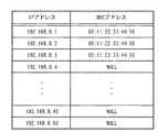
図9は、本実施形態におけるアドレス管理テーブルの一例を示す図である。図9に示すように、アドレス管理テーブルには、IPアドレスとMACアドレスとが対応付けられて保存されている。また、IPアドレスは、割り当て可能なIPアドレスが全て保存されている。ここで、IPアドレスの割り当てが完了すると、割り当てたIPアドレスに割当先の通信機器を識別するMACアドレスが対応付けられて保存される。また、未割り当てのIPアドレスに対応するMACアドレスには、NULL情報(0)が保存されている。 FIG. 9 is a diagram showing an example of an address management table in the present embodiment. As shown in FIG. 9, the IP address and the MAC address are stored in the address management table in association with each other. As for IP addresses, all assignable IP addresses are stored. Here, when the assignment of the IP address is completed, the assigned IP address is stored in association with the MAC address for identifying the assigned communication device. Also, NULL information (0) is stored in the MAC address corresponding to the unassigned IP address.
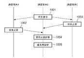
図10は、本実施形態における優先度の設定の一例を示すシーケンス図である。図10に示す一例では、ネットワークに参加した順に優先度を高く設定する。また、2台の通信端末A、Cが存在し、新たに通信端末Bがネットワークに参加する場合である。 FIG. 10 is a sequence diagram illustrating an example of priority setting in the present embodiment. In the example shown in FIG. 10, the priority is set higher in the order of participation in the network. Further, there are two communication terminals A and C, and a new communication terminal B joins the network.
まず処理1001で、図4により説明したように、通信端末Bがサービス検索フレームをブロードキャストし、所望のサービスを提供している通信端末の発見要求を行う。これにより、処理1002及び処理1003で、通信端末A及び通信端末Cが、サービス応答フレームを送信すると、通信端末Bは処理1004で、サービス応答フレームを受信すると共に、受信したサービス応答フレームの数を数える。そして、処理1005で、上述の処理1004で数えたサービス応答フレームの数を優先度として設定する。 First, in the
尚、本実施形態では、サービス検索フレームと、そのサービス検索フレームに対応したサービス応答フレームを用いたが、計数用に独立のフレームを設けても良いし、また他のフレームを利用しても良い。 In this embodiment, a service search frame and a service response frame corresponding to the service search frame are used. However, an independent frame may be provided for counting, or another frame may be used. .
また、本実施形態では、無線ネットワークを例に説明したが、有線ネットワークに適用することも可能である。また、無線通信機能付撮像装置と、無線通信機能付印字装置とを例に説明したが、他の機能を有した無線通信端末に適用することも可能である。 In the present embodiment, a wireless network has been described as an example, but the present invention can also be applied to a wired network. In addition, the imaging apparatus with a wireless communication function and the printing apparatus with a wireless communication function have been described as examples, but the present invention can also be applied to a wireless communication terminal having other functions.
尚、本発明は複数の機器(例えば、ホストコンピュータ,インターフェース機器,リーダ,プリンタなど)から構成されるシステムに適用しても、1つの機器からなる装置(例えば、複写機,ファクシミリ装置など)に適用しても良い。 Even if the present invention is applied to a system composed of a plurality of devices (for example, a host computer, an interface device, a reader, a printer, etc.), it is applied to an apparatus (for example, a copier, a facsimile machine, etc.) composed of a single device. It may be applied.
また、本発明の目的は前述した実施形態の機能を実現するソフトウェアのプログラムコードを記録した記録媒体を、システム或いは装置に供給し、そのシステム或いは装置のコンピュータ(CPU若しくはMPU)が記録媒体に格納されたプログラムコードを読出し実行することによっても、達成されることは言うまでもない。 Another object of the present invention is to supply a recording medium in which a program code of software realizing the functions of the above-described embodiments is recorded to a system or apparatus, and the computer (CPU or MPU) of the system or apparatus stores the recording medium in the recording medium. Needless to say, this can also be achieved by reading and executing the programmed program code.
この場合、記録媒体から読出されたプログラムコード自体が前述した実施形態の機能を実現することになり、そのプログラムコードを記憶した記録媒体は本発明を構成することになる。 In this case, the program code itself read from the recording medium realizes the functions of the above-described embodiment, and the recording medium storing the program code constitutes the present invention.
このプログラムコードを供給するための記録媒体としては、例えばフロッピー(登録商標)ディスク,ハードディスク,光ディスク,光磁気ディスク,CD−ROM,CD−R,磁気テープ,不揮発性のメモリカード,ROMなどを用いることができる。 As a recording medium for supplying the program code, for example, a floppy (registered trademark) disk, a hard disk, an optical disk, a magneto-optical disk, a CD-ROM, a CD-R, a magnetic tape, a nonvolatile memory card, a ROM, or the like is used. be able to.
また、コンピュータが読出したプログラムコードを実行することにより、前述した実施形態の機能が実現されるだけでなく、そのプログラムコードの指示に基づき、コンピュータ上で稼働しているOS(オペレーティングシステム)などが実際の処理の一部又は全部を行い、その処理によって前述した実施形態の機能が実現される場合も含まれることは言うまでもない。 Further, by executing the program code read by the computer, not only the functions of the above-described embodiments are realized, but also an OS (operating system) operating on the computer based on the instruction of the program code. It goes without saying that a case where the function of the above-described embodiment is realized by performing part or all of the actual processing and the processing is included.
更に、記録媒体から読出されたプログラムコードが、コンピュータに挿入された機能拡張ボードやコンピュータに接続された機能拡張ユニットに備わるメモリに書込まれた後、そのプログラムコードの指示に基づき、その機能拡張ボードや機能拡張ユニットに備わるCPUなどが実際の処理の一部又は全部を行い、その処理によって前述した実施形態の機能が実現される場合も含まれることは言うまでもない。 Further, after the program code read from the recording medium is written in a memory provided in a function expansion board inserted into the computer or a function expansion unit connected to the computer, the function expansion is performed based on the instruction of the program code. It goes without saying that the CPU or the like provided in the board or the function expansion unit performs part or all of the actual processing and the functions of the above-described embodiments are realized by the processing.
101 無線通信機能付撮像装置
102 無線通信機能付印字装置
103 第2の無線通信機能付撮像装置
104 第2の無線通信機能付印字装置
105 無線通信機能付記録装置
106 無線通信機能付端末101 Imaging Device with
Claims (25)
Translated fromJapanese物理的アドレスに対して論理的アドレスを割り当てるアドレス割り当て工程と、
他の通信端末で割り当てられた論理的アドレスを取得するアドレス取得工程と、
前記アドレス割り当て工程か、アドレス取得工程の何れかを有効とする切り替え工程とを有することを特徴とするアドレス割り当て方法。An address assignment method for a communication network that communicates using a physical address that physically identifies a plurality of communication terminals and a logical address that logically identifies the plurality of communication terminals,
An address assignment step for assigning a logical address to a physical address;
An address acquisition step of acquiring a logical address assigned by another communication terminal;
An address assignment method comprising: a switching step for validating either the address assignment step or the address acquisition step.
各ネットワーク識別子情報及び各チャネル情報を切り換えつつ、通信端末発見要求を送信し、所望の通信端末発見応答が受信されたネットワーク識別子情報及びチャネル情報を選択し、該ネットワーク識別子情報及びチャネル情報により決定される通信ネットワークにおいて通信を行うことを特徴とした請求項1記載のアドレス割り当て方法。A communication network in which communication is performed simultaneously with a communication terminal in which channel identifier information for identifying a network that performs communication and channel information that is a frequency band for performing communication match.
While switching each network identifier information and each channel information, a communication terminal discovery request is transmitted, a desired communication terminal discovery response is received, network identifier information and channel information are selected, and determined by the network identifier information and channel information. 2. The address assignment method according to claim 1, wherein communication is performed in a communication network.
Priority Applications (1)
| Application Number | Priority Date | Filing Date | Title |
|---|---|---|---|
| JP2004090061AJP2005277937A (en) | 2004-03-25 | 2004-03-25 | Communication method and communication apparatus |
Applications Claiming Priority (1)
| Application Number | Priority Date | Filing Date | Title |
|---|---|---|---|
| JP2004090061AJP2005277937A (en) | 2004-03-25 | 2004-03-25 | Communication method and communication apparatus |
Publications (1)
| Publication Number | Publication Date |
|---|---|
| JP2005277937Atrue JP2005277937A (en) | 2005-10-06 |
Family
ID=35177113
Family Applications (1)
| Application Number | Title | Priority Date | Filing Date |
|---|---|---|---|
| JP2004090061AWithdrawnJP2005277937A (en) | 2004-03-25 | 2004-03-25 | Communication method and communication apparatus |
Country Status (1)
| Country | Link |
|---|---|
| JP (1) | JP2005277937A (en) |
Cited By (16)
| Publication number | Priority date | Publication date | Assignee | Title |
|---|---|---|---|---|
| JP2007201650A (en)* | 2006-01-25 | 2007-08-09 | Nec Infrontia Corp | Radio communication system, radio lan base station and method for confirming/changing set content used for these system and base station |
| JP2009049576A (en)* | 2007-08-15 | 2009-03-05 | Canon Inc | Communication apparatus and communication method thereof |
| CN102256103A (en)* | 2010-05-20 | 2011-11-23 | 鸿富锦精密工业(深圳)有限公司 | Application server and method for realizing camera control |
| DE102008055033B4 (en)* | 2007-12-20 | 2012-11-08 | Realtek Semiconductor Corp. | Circuit and method for setting data and their application in integrated circuits |
| WO2013078814A1 (en)* | 2011-12-01 | 2013-06-06 | 中兴通讯股份有限公司 | Ip address allocation method and device |
| JP2013141273A (en)* | 2013-02-12 | 2013-07-18 | Canon Inc | Communication apparatus and communication method therefor |
| JP2014045505A (en)* | 2007-05-29 | 2014-03-13 | Canon Inc | Wireless communication apparatus and control method therefor |
| WO2014103656A1 (en)* | 2012-12-27 | 2014-07-03 | Canon Kabushiki Kaisha | Communication apparatus, control method, and computer-readable storage medium |
| WO2014115612A1 (en)* | 2013-01-25 | 2014-07-31 | キヤノン株式会社 | Communication apparatus, method for controlling communication apparatus, program |
| JP2014175748A (en)* | 2013-03-07 | 2014-09-22 | Nec Access Technica Ltd | Network device and control method therefor |
| JP2014207699A (en)* | 2014-06-30 | 2014-10-30 | キヤノン株式会社 | Communication device and communication method therefor |
| JP2018148301A (en)* | 2017-03-02 | 2018-09-20 | 任天堂株式会社 | Radio communication system, communication method, information processing device, and information processing program |
| JP2019036775A (en)* | 2017-08-10 | 2019-03-07 | キヤノン株式会社 | Communication apparatus, control method, and program |
| JP2019161679A (en)* | 2019-07-01 | 2019-09-19 | キヤノン株式会社 | Communication device, control method, and program |
| US10430138B2 (en) | 2017-08-10 | 2019-10-01 | Canon Kabushiki Kaisha | Communication apparatus |
| WO2024147563A1 (en)* | 2023-01-04 | 2024-07-11 | 주식회사 엘지에너지솔루션 | Battery system control apparatus and operating method thereof |
- 2004
- 2004-03-25JPJP2004090061Apatent/JP2005277937A/ennot_activeWithdrawn
Cited By (27)
| Publication number | Priority date | Publication date | Assignee | Title |
|---|---|---|---|---|
| US8189545B2 (en) | 2006-01-25 | 2012-05-29 | Nec Infrontia Corporation | Wireless communication system, wireless LAN access point and settings confirmation/change method used therefor |
| JP2007201650A (en)* | 2006-01-25 | 2007-08-09 | Nec Infrontia Corp | Radio communication system, radio lan base station and method for confirming/changing set content used for these system and base station |
| JP2014045505A (en)* | 2007-05-29 | 2014-03-13 | Canon Inc | Wireless communication apparatus and control method therefor |
| JP2009049576A (en)* | 2007-08-15 | 2009-03-05 | Canon Inc | Communication apparatus and communication method thereof |
| CN102364923A (en)* | 2007-08-15 | 2012-02-29 | 佳能株式会社 | Communication apparatus and control method thereof |
| DE102008055033B4 (en)* | 2007-12-20 | 2012-11-08 | Realtek Semiconductor Corp. | Circuit and method for setting data and their application in integrated circuits |
| US9473344B2 (en) | 2007-12-20 | 2016-10-18 | Realtek Semiconductor Corporation | Circuit and method for setting data and their application to integrated circuit |
| CN102256103B (en)* | 2010-05-20 | 2014-12-10 | 南通新业电子有限公司 | Application server and method for realizing camera control |
| CN102256103A (en)* | 2010-05-20 | 2011-11-23 | 鸿富锦精密工业(深圳)有限公司 | Application server and method for realizing camera control |
| WO2013078814A1 (en)* | 2011-12-01 | 2013-06-06 | 中兴通讯股份有限公司 | Ip address allocation method and device |
| KR101770049B1 (en)* | 2012-12-27 | 2017-08-21 | 캐논 가부시끼가이샤 | Communication apparatus, control method, and computer-readable storage medium |
| JP2014128018A (en)* | 2012-12-27 | 2014-07-07 | Canon Inc | Communication device, control method and program |
| WO2014103656A1 (en)* | 2012-12-27 | 2014-07-03 | Canon Kabushiki Kaisha | Communication apparatus, control method, and computer-readable storage medium |
| WO2014115612A1 (en)* | 2013-01-25 | 2014-07-31 | キヤノン株式会社 | Communication apparatus, method for controlling communication apparatus, program |
| JP2014143634A (en)* | 2013-01-25 | 2014-08-07 | Canon Inc | Communication apparatus, method for controlling communication apparatus, and program |
| US9602579B2 (en) | 2013-01-25 | 2017-03-21 | Canon Kabushiki Kaisha | Communication apparatus, method for controlling the same, and program |
| JP2013141273A (en)* | 2013-02-12 | 2013-07-18 | Canon Inc | Communication apparatus and communication method therefor |
| JP2014175748A (en)* | 2013-03-07 | 2014-09-22 | Nec Access Technica Ltd | Network device and control method therefor |
| JP2014207699A (en)* | 2014-06-30 | 2014-10-30 | キヤノン株式会社 | Communication device and communication method therefor |
| JP2018148301A (en)* | 2017-03-02 | 2018-09-20 | 任天堂株式会社 | Radio communication system, communication method, information processing device, and information processing program |
| JP2019036775A (en)* | 2017-08-10 | 2019-03-07 | キヤノン株式会社 | Communication apparatus, control method, and program |
| US10430138B2 (en) | 2017-08-10 | 2019-10-01 | Canon Kabushiki Kaisha | Communication apparatus |
| US10936267B2 (en) | 2017-08-10 | 2021-03-02 | Canon Kabushiki Kaisha | Communication apparatus |
| US11334306B2 (en) | 2017-08-10 | 2022-05-17 | Canon Kabushiki Kaisha | Communication apparatus |
| JP2019161679A (en)* | 2019-07-01 | 2019-09-19 | キヤノン株式会社 | Communication device, control method, and program |
| JP7016839B2 (en) | 2019-07-01 | 2022-02-07 | キヤノン株式会社 | Communication equipment, control methods and programs |
| WO2024147563A1 (en)* | 2023-01-04 | 2024-07-11 | 주식회사 엘지에너지솔루션 | Battery system control apparatus and operating method thereof |
Similar Documents
| Publication | Publication Date | Title |
|---|---|---|
| US7554979B2 (en) | Communication apparatus and method having function of transmitting notification signal while hiding group identification information | |
| JP4475639B2 (en) | Wireless terminal apparatus, control method thereof and communication control method | |
| JP4125173B2 (en) | Information processing apparatus connection control method, information processing apparatus, and computer program | |
| JP2005277937A (en) | Communication method and communication apparatus | |
| US20180324139A1 (en) | Communication apparatus and communication method therefor | |
| US20150334749A1 (en) | Communication apparatus, control method, and computer-readable storage medium | |
| JP6271843B2 (en) | COMMUNICATION DEVICE, ITS CONTROL METHOD, PROGRAM | |
| JP4549207B2 (en) | COMMUNICATION DEVICE AND ITS CONTROL METHOD | |
| US10021004B2 (en) | Communication device, control method for communication device, and program | |
| WO2020250713A1 (en) | Communication device, control method of communication device, and program | |
| US9882880B2 (en) | Communication apparatus, method for controlling the same, and storage medium | |
| US9979792B2 (en) | Communication apparatus that, in a direct printing mode, is controlled not to transfer a search signal to another printer regardless of the state of the other printer, control method therefor, and storage medium | |
| KR20190020624A (en) | Information processing apparatus, control method and recording medium | |
| US10098161B2 (en) | Information processing apparatus and non-transitory computer readable medium | |
| US11368989B2 (en) | Information processing apparatus, method of controlling the same, and program | |
| KR102208987B1 (en) | Communication device, communication method, and program | |
| JP7721597B2 (en) | Electronic device, control method thereof, program, and storage medium | |
| JP2006173948A (en) | Document processing system | |
| JP4412721B2 (en) | Control method in wireless communication system | |
| JP2025006818A (en) | Electronic device, information terminal, control method thereof, program, and storage medium | |
| CN119233337A (en) | Electronic device, method for controlling electronic device, and storage medium | |
| CN117651098A (en) | Information processing apparatus, control method, and storage medium | |
| JP6584106B2 (en) | COMMUNICATION DEVICE, ITS CONTROL METHOD, PROGRAM | |
| JP2025006816A (en) | Electronic device, control method thereof, program, and storage medium | |
| CN118590583A (en) | Printing device, printing device control method, and recording medium |
Legal Events
| Date | Code | Title | Description |
|---|---|---|---|
| A300 | Application deemed to be withdrawn because no request for examination was validly filed | Free format text:JAPANESE INTERMEDIATE CODE: A300 Effective date:20070605 |