JP2005267662A - Print processing method and print processing system - Google Patents
Print processing method and print processing systemDownload PDFInfo
- Publication number
- JP2005267662A JP2005267662AJP2005158091AJP2005158091AJP2005267662AJP 2005267662 AJP2005267662 AJP 2005267662AJP 2005158091 AJP2005158091 AJP 2005158091AJP 2005158091 AJP2005158091 AJP 2005158091AJP 2005267662 AJP2005267662 AJP 2005267662A
- Authority
- JP
- Japan
- Prior art keywords
- unit
- user interface
- marking device
- information
- Prior art date
- Legal status (The legal status is an assumption and is not a legal conclusion. Google has not performed a legal analysis and makes no representation as to the accuracy of the status listed.)
- Pending
Links
- 238000012545processingMethods0.000titleclaimsabstractdescription78
- 238000003672processing methodMethods0.000titleclaimsabstractdescription11
- 230000008859changeEffects0.000claimsabstractdescription6
- 238000012544monitoring processMethods0.000claimsdescription7
- 238000004891communicationMethods0.000abstractdescription44
- 238000000034methodMethods0.000abstractdescription25
- 230000008569processEffects0.000abstractdescription12
- 238000007726management methodMethods0.000description26
- 238000010586diagramMethods0.000description15
- 230000006870functionEffects0.000description13
- 238000011161developmentMethods0.000description12
- 238000012937correctionMethods0.000description8
- 239000003795chemical substances by applicationSubstances0.000description7
- 238000012546transferMethods0.000description7
- 238000006243chemical reactionMethods0.000description6
- 239000004065semiconductorSubstances0.000description6
- 230000005540biological transmissionEffects0.000description4
- 230000004044responseEffects0.000description4
- 230000007274generation of a signal involved in cell-cell signalingEffects0.000description3
- 239000003086colorantSubstances0.000description2
- 230000003287optical effectEffects0.000description2
- 230000002159abnormal effectEffects0.000description1
- 230000005856abnormalityEffects0.000description1
- 230000015572biosynthetic processEffects0.000description1
- 238000002716delivery methodMethods0.000description1
- 238000009792diffusion processMethods0.000description1
- 230000000694effectsEffects0.000description1
- 230000003203everyday effectEffects0.000description1
- 239000000284extractSubstances0.000description1
- 238000003384imaging methodMethods0.000description1
- 238000012423maintenanceMethods0.000description1
- 230000007246mechanismEffects0.000description1
- 230000002093peripheral effectEffects0.000description1
- 238000002360preparation methodMethods0.000description1
- 230000009467reductionEffects0.000description1
- 230000008439repair processEffects0.000description1
- 239000013598vectorSubstances0.000description1
Images


Abstract
Description
Translated fromJapanese本発明は印刷処理方法および印刷処理システムに関し、特に用紙上にイメージを生成するマーキング装置とマーキング装置の特性に合わせて処理するイメージングコントローラとを組み合わせて機能する印刷処理方法および印刷処理システムに関する。 The present invention relates to a print processing method and a print processing system, and more particularly to a print processing method and a print processing system that function in combination with a marking device that generates an image on a sheet and an imaging controller that performs processing according to the characteristics of the marking device.
小型、高速のディジタル印刷に適した電子写真方式のページプリンタの開発に伴い、従来の文字情報中心の印刷から脱皮した、画像、図形、文字などを同様に取り扱い、図形、文字などの拡大、回転、変形などが自由に制御できる記述言語を用いる印刷処理装置が一般に普及してきた。このような記述言語の代表的な例として、PostScript(Adobe Systems社商標)、Interpress(Xerox社商標)、Acrobat(Adobe Systems社商標)、GDI(Graphics Device Interface、Microsoft社商標)などが知られている。 Accompanying the development of a small and high-speed electrophotographic page printer suitable for digital printing, images, graphics, and characters are handled in the same way, and the graphics and characters are enlarged and rotated. In general, print processing apparatuses using a description language in which deformation and the like can be freely controlled have been widely used. Representative examples of such a description language include PostScript (trademark of Adobe Systems), Interpress (trademark of Xerox), Acrobat (trademark of Adobe Systems), GDI (Graphics Devices Interface, Microsoft, etc.). Yes.
記述言語で作成されている印刷データは、ページ内の任意の位置の画像、図形、文字を表現する描画命令およびデータを任意の順で配置した命令およびデータ列で構成されており、ページプリンタで印字するためには、印字前に印刷データをラスタ化しなければならない。ラスタ化というのは、ページまたはページの一部を横切る一連の個々のドットまたは画素へ展開してラスタ走査線を形成し、そのページの下へ引き続く走査線を次々に発生する過程である。 The print data created in the description language consists of a command and data sequence in which drawing commands and data representing images, figures, and characters in any position in the page are arranged in any order. In order to print, the print data must be rasterized before printing. Rasterization is the process of developing raster scan lines into a series of individual dots or pixels across a page or part of a page, and successively generating scan lines below the page.
この印刷データからラスタデータヘの展開は非常に大きな計算量を伴うものであるため、この処理を高速化するために専用ハードウェアを利用することが考えられている。専用ハードウェアを用いた一例として、特開平6−86032号公報が知られている。この公報に記載の技術によれば、まず、記述言語で作成されている印刷データの構文を解釈し、ベクタで表される描画命令の集合に変換する。次に、専用ハードウェアで展開処理可能な中間データに変換する。ここまでの処理はソフトウェアで行われる。1ページ分の中問データの生成が終了すると、マーキング装置(プリンタ)に起動をかけ、専用ハードウェアはそのマーキング装置の要求するスピードで中間データからラスタデータの変換を行い、マーキング装置にラスタデータを転送するという処理を行う。 Since development from this print data to raster data involves a very large amount of calculation, it is considered to use dedicated hardware in order to speed up this processing. JP-A-6-86032 is known as an example using dedicated hardware. According to the technique described in this publication, first, the syntax of print data created in a description language is interpreted and converted into a set of drawing commands represented by vectors. Next, the data is converted into intermediate data that can be expanded by dedicated hardware. The processing so far is performed by software. When the generation of intermediate data for one page is completed, the marking device (printer) is activated, and the dedicated hardware converts the raster data from the intermediate data at the speed required by the marking device. The process of transferring is performed.
この専用ハードウェアは特定のマーキング装置に対してカスタマイズされたものであり、他の機種のマーキング装置に出力する場合は専用ハードウェアの一部の回路を交換するか、これらの回路をマーキング装置に応じて並列的に用意しておく必要がある。 This dedicated hardware is customized for a specific marking device. When outputting to other types of marking devices, replace some of the circuits of the dedicated hardware, or replace these circuits with the marking device. It is necessary to prepare in parallel accordingly.
また、一つの専用ハードウェアを用いて複数種のマーキング装置に出力する場合も、それぞれのマーキング装置にカスタマイズされた回路を並列的に用意しておく必要がある。しかしながら、中問データからラスタデータへの展開処理を行うという同じような処理をするにも拘らず、それぞれのマーキング装置にカスタマイズされた回路を並列的に複数用意することは、使用率を考えればたいへん無駄であるともに、新たな機種のマーキング装置を使用する場合はそのマーキング装置の仕様に合わせた回路を追加しなければならないという問題がある。 Also, when outputting to a plurality of types of marking devices using one dedicated hardware, it is necessary to prepare customized circuits in parallel for each marking device. However, in spite of the same process of developing the middle data to raster data, it is necessary to prepare a plurality of customized circuits in parallel in each marking device in consideration of the usage rate. In addition to being very useless, there is a problem that when a new type of marking device is used, a circuit that matches the specifications of the marking device must be added.
本発明は以上のような点に鑑みてなされたものであり、マーキング装置の仕様に合った機種ごとの回路を必要とせずに複数のマーキング装置に接続して印刷処理を可能にする印刷処理方法および印刷処理システムを提供することを目的とする。 The present invention has been made in view of the above points, and a printing processing method that enables printing processing by connecting to a plurality of marking devices without requiring a circuit for each model that meets the specifications of the marking device. And a print processing system.
本発明では上記問題を解決するために、マーキング装置に対してユーザインタフェース部で前記マーキング装置に対する装置状態監視または印刷指示を行う印刷処理方法において、前記ユーザインタフェース部で表示されるユーザインタフェースを前記マーキング装置と整合するように変更制御することを特徴とする印刷処理方法が提供される。 In the present invention, in order to solve the above-described problem, in the printing processing method in which the user interface unit monitors the device status or prints the marking device with respect to the marking device, the user interface displayed on the user interface unit is the marking device. There is provided a print processing method characterized in that change control is performed so as to be consistent with an apparatus.
このような印刷処理方法によれば、ユーザインタフェース部で表示されるユーザインタフェースをマーキング装置と整合するように変更制御することにより、機種によってそれぞれ異なるマーキング装置のユーザインタフェースを変更することができるので、ユーザインタフェース部は、同一のハードウェア資源を用いて複数機種のマーキング装置に対応したユーザインタフェースで印刷処理を行うことができ、機種ごとに専用ハードウェアの一部の回路を並列的に用意する必要がなくなる。 According to such a printing processing method, by changing and controlling the user interface displayed on the user interface unit so as to be consistent with the marking device, the user interface of the different marking device can be changed depending on the model, The user interface unit can perform printing with a user interface that supports multiple types of marking devices using the same hardware resources, and it is necessary to prepare some dedicated hardware circuits in parallel for each model. Disappears.
また、本発明では、マーキング装置に対してユーザインタフェース部で前記マーキング装置に対する装置状態監視または印刷指示を行う印刷処理システムにおいて、前記ユーザインタフェース部で表示されるユーザインタフェースを前記マーキング装置と整合するように変更制御する制御装置を備えたことを特徴とする印刷処理システムが提供される。 According to the present invention, in a print processing system that performs a device status monitoring or a print instruction for the marking device at the user interface unit with respect to the marking device, the user interface displayed on the user interface unit is matched with the marking device. There is provided a print processing system characterized by comprising a control device for performing change control.
このような印刷処理システムによれば、制御装置がユーザインタフェース部で表示されるユーザインタフェースをマーキング装置と整合するように変更制御することができるので、ユーザインタフェース部は、同一のハードウェア資源を用いて複数機種のマーキング装置に対応したユーザインタフェースで印刷処理を行うことができ、機種ごとに専用ハードウェアの一部の回路を並列的に用意する必要がなくなる。 According to such a print processing system, since the control device can change and control the user interface displayed on the user interface unit so as to match the marking device, the user interface unit uses the same hardware resource. Thus, it is possible to perform printing processing with a user interface corresponding to a plurality of types of marking apparatuses, and it is not necessary to prepare a part of circuits of dedicated hardware in parallel for each model.
本発明ではマーキング装置の機種によって異なる処理を行うユーザインタフェース部のユーザインタフェースをマーキング装置と整合するように変更制御するようにした。これにより、マーキング装置への印刷指示やマーキング装置の状態管理を行うユーザインタフェース部と、マーキング装置と、印刷処理装置との間で通信の内容を適宜同一のハードウェアで再構成を行うことでマーキング装置ごとに異なったプロトコルデコード情報をもとに通信を行うことができ、通信の高速処理化が可能になる。ユーザインタフェース部では、各種のマーキング装置や印刷処理装置での通信の内容は、ユーザがそれぞれのプロトコル特性を意識することなく正常に通信できるように変換される。 In the present invention, the user interface of the user interface unit that performs different processing depending on the type of the marking device is changed and controlled so as to match the marking device. As a result, marking is performed by appropriately reconfiguring the content of communication between the user interface unit that performs printing instructions to the marking device and the status management of the marking device, the marking device, and the print processing device. Communication can be performed based on different protocol decode information for each apparatus, and high-speed processing of communication is possible. In the user interface unit, the contents of communication in various marking devices and print processing devices are converted so that the user can normally communicate without being aware of the respective protocol characteristics.
また、通信内容には多くの種類があるがそれらを適宜外部より再構成できるため、マーキング装置の機種に応じたインタフェースを個々に用意する必要がなく、再構成ハードウェアを用いることで汎用的でかつ高速処理を実現できる。 In addition, there are many types of communication content, but they can be reconfigured from the outside as needed, so there is no need to prepare individual interfaces according to the model of the marking device. In addition, high-speed processing can be realized.
以下、本発明の実施の形態を図面を参照して説明する。
図1は本発明による印刷処理装置の原理図である。本発明の印刷処理装置1は印刷を行うマーキング装置2に接続されて、入力された印刷データを印刷可能な画像データに変換してマーキング装置2に渡すもので、印刷データを入力する印刷データ入力手段1aと、印刷データ展開処理手段1bと、再構成インタフェース手段1cとから構成されている。Hereinafter, embodiments of the present invention will be described with reference to the drawings.
FIG. 1 is a principle diagram of a print processing apparatus according to the present invention. The print processing apparatus 1 of the present invention is connected to a marking
外部より画像、図形、文字などを描画するために命令およびデータ列を有する印刷データが印刷処理装置1に入力されると、印刷データ入力手段1aがその印刷データを受け付け、印刷データ展開処理手段1bに渡す。印刷データ展開処理手段1bは受け取った印刷データを解析し、中間データを作成する。その後、印刷データ展開処理手段1bは中間データをマーキング装置2の特性に合わせてビットマップデータに展開し、再構成インタフェース手段1cを介してマーキング装置2に出力する。マーキング装置2は印刷処理装置1からのビットマップデータをもとに印刷を行う。ここで、再構成インタフェース手段1cは機種によってそれぞれ異なるマーキング装置2の通信内容を印刷処理装置1が扱う共通の通信内容と相互変換する機能を有している。再構成インタフェース手段1cはハードウェアの構成をソフトウェアによって再構成可能な手段が用いられ、接続されるマーキング装置2の仕様に合わせて相互変換機能が変更される。これにより、マーキング装置2の機種ごとに専用ハードウェアの一部の回路を並列的に用意し、これらを交換して使用するという必要がなくなる。 When print data having an instruction and a data string for drawing an image, a figure, a character, etc. is input from the outside to the print processing apparatus 1, the print data input means 1a accepts the print data, and the print data expansion processing means 1b. To pass. The print data expansion processing unit 1b analyzes the received print data and creates intermediate data. Thereafter, the print data expansion processing unit 1b expands the intermediate data into bitmap data in accordance with the characteristics of the
次に、本発明の印刷処理装置を印刷処理システムに適用した場合の実施の形態について説明する。
図2は印刷処理システムの一構成例を示すブロック図である。図2において、印刷処理システムは、ユーザインタフェース部10と、コントローラ20と、マーキング装置30から構成されている。コントローラ20は印刷データ入力部21と、展開処理部22と、制御部23と、再構成インタフェース部24とから成っており、マーキング装置30は出力部31と出力部制御管理部32とから成っている。Next, an embodiment when the print processing apparatus of the present invention is applied to a print processing system will be described.
FIG. 2 is a block diagram illustrating a configuration example of the print processing system. In FIG. 2, the print processing system includes a
ユーザインタフェース部10はWindows(米国Microsoft社の米国およびその他の国における登録商標)などの汎用オペレーティングシステム上で動作するアプリケーションソフトウェアと連動して、印刷データをどのマーキング装置で印刷するのか、何部印刷したいのかなどをディスプレイ画面を使って指示する機能と、コントローラ20やマーキング装置30が正常に動作しているかなどの状態をモニタする機能を持っている。 The
コントローラ20の印刷データ入力部21は、印字を行う印刷データを生成する機能を備えたアプリケーションプログラムである。本実施の形態で説明する印刷データはPostScriptで代表されるページ記述言語で記述されたものである。 The print
コントローラ20は、印刷データ入力部21より入力された印刷データを印刷可能な画像データに変換する。まず、展開処理部22では一旦展開処理可能な中間データを生成する。中間データを生成する目的は、展開処理部22での高速な展開処理を可能にすることである。そのため、展開処理部22は、印刷データをマーキング装置30の特性に合わせて記述内容を印刷できるデータに変換する。中間データは単純な図形(台形)の集合で表されている。この中間データの最少単位はオブジェクトであり、各々のオブジェクトには処理内容に関する情報が付加されている。ここでの処理内容とは、たとえば図形処理、文字処理、画像処理などに必要な処理群である。マーキング装置30の特性にもよるが、電子写真のような一定速度で印刷する装置では一旦1ページ分の中間データを作成する。その後、ハードウェアまたはソフトウェアでビットマップデータに展開し、マーキング装置30の出力部31に転送する役割を持つ。 The
制御部23はユーザインタフェース部10からの情報、マーキング装置30からの情報を受け取り、全体が正常に動作するように制御や制御のための通信を行う部分である。
再構成インタフェース部24はマーキング装置30の仕様にあわせてコントローラ20とマーキング装置30をハード的、ソフト的に接続する部分であり、マーキングするための画像データをインタフェースする部分と、出力部制御管理部32と通信する部分とを備えている。この再構成インタフェース部24の回路は、たとえばFPGA(Field Programmable Gate Array)のようにソフトウェアでハードウェアの内容を制御出来る素子を用いて実現され、ハード的およびソフト的に接続する部分の内容がマーキング装置30の仕様に合わせて再構成される。The
The
マーキング装置30の出力部31は、展開処理部22から出力される印字データを再構成インタフェース部24を経由して受け取って、記録用紙に印字し、出力するものである。出力部31はたとえば後述の図3に示すような電子写真方式を使ったカラーのマーキング装置であれば、C、M、Y、BK (シアン、マゼンタ、イエロー、ブラック)カラーの色ごとに露光、現像、転写を繰り返すことによりフルカラー画像を出力できるレーザー走査方式の電子写真方式を用いたカラーページプリンタである。もちろん、出力部31は、インクジェット方式のカラープリンタでもよい。 The
出力部制御管理部32は、マーキング装置30を構成する各種モジュールを動作させることで紙送り、画像形成、用紙排出、正常終了監視などを行う出力部制御部(図示せず)とリンクして、コントローラ20側と通信し、マーキングが効率よく正常に動作するための情報を備えており、現在接続されている出力部31の形態情報、動作情報や属性情報を保持し、管理する。形態情報とはマーキング装置30に依存して接続動作させるためにあらかじめ必要な情報で画像データの受け渡し方式、通信方式、プロトコル形式、動作タイミングなどである。動作情報とはマーキング装置30の動作に関するユーザインタフェース部で指示される用紙サイズや印刷枚数などの設定と動作管理であり、属性情報とは、たとえば出力解像度、各ピクセルの階調数、出力色、印字方式、スクリーン方式などのマーキング装置30のデバイス特性などである。これらの情報はコントローラ20とマーキング装置30とが接続されるための重要な情報である。出力部31に合わせた内容はあらかじめ出力部制御管理部32内に保持しているか、問い合わせることによって収集するか、あるいは管理者が入力する。 The output unit
ここで、一般的なレーザー走査方式の電子写真方式を用いたカラーページプリンタの構成および動作について説明する。
図3はカラーページプリンタの構成例を示す図である。図3において、ビデオインタフェース311は、展開処理部22から順次送られてくるCMYBK の色情報に対応した印刷データを図示されない半導体レーザーの点灯を制御するドライバへ入力して光信号に変換する。半導体レーザー走査装置312は、赤外半導体レーザー、レンズ3121、ポリゴンミラー3122より構成され、数十μmのスポット光となって感光体ドラム313を走査する。感光体ドラム313は、帯電器314により帯電されており、光信号により、静電潜像が形成される。潜像はロータリ現像器315上の2成分磁気ブラシ現像によりトナー像となり、転写ドラム316上に吸着させた用紙上に転写される。感光体ドラム313は、クリーナ317で余分のトナーがクリーニングされる。この工程をBK 、Y、M、Cの順に繰り返し、用紙上に多重転写する。最後に、転写ドラム316より用紙を剥離し、定着器318でトナーを定着する。Here, the configuration and operation of a color page printer using a general laser scanning type electrophotographic system will be described.
FIG. 3 is a diagram illustrating a configuration example of a color page printer. In FIG. 3, a
まず、印刷実行に先立って、コンピュータにあるユーザインタフェース部10とコントローラ20とマーキング装置30とが接続される。ユーザインタフェース部10とコントローラ20とはハードウェアとしてコンピュータの周辺機器となり、コンピュータの備えた汎用的なインタフェース方式、たとえばネットワークであればイーサネット(登録商標)、ローカルバスであればUSB(Universal Serial Bus)やIEEE1394、SCSI(Small Computer System Interface)などがある。出力部制御管理部32は、出力部31に形態情報、動作情報、属性情報を問い合わせ、その結果を管理し、再構成データとして使用する。なお、出力部31にこのような問い合わせに答える機能がない場合は、管理者がユーザインタフェース部10などを経由してコントローラ20に入力してもよい。 First, prior to execution of printing, the
ユーザインタフェース部10で指示された印刷データは印刷データ入力部21に入力される。印刷データは、順次展開処理部22に渡される。展開処理部22は言語解釈処理で描画命令群を抽出し、中間データと呼ばれる台形オブジェクトの集合に変換する。中間データは、画像、文字、図形などの種類に分けて処理され、各々のオブジェクトに画像、文字、図形などの種類が分かる情報、描画の属性、オブジェクトの外接矩形が付加される。さらに展開処理部22では、出力部制御管理部32から得た情報の一部をもとに中間データをデバイス特性に合わせて展開処理し、展開処理の結果であるビットマップを展開処理部22の内部に一時保持する。これを1ページ分の印刷データすべてを処理するまで実行する。1ページ分のデータ処理が終了すると、展開処理部22からマーキング装置30の記録速度に応じて印字データが1ラインごとに転送され、印字が行われる。展開処理部22から出力部31への印字データの転送は、1ページ分の印刷データが転送されるまで、色ごとにあるいは4色同時に繰り返される。または、中間データをまず1ページ分生成し、中間データの展開はマーキング装置30に同期して1ラインごとに転送され、印字が行われる形式もある。 The print data instructed by the
以上、本発明の印刷処理装置を適用した印刷処理システムの概要について記述した。次に、コントローラ20の再構成インタフェース部24の詳細を中心に説明する。
図4は再構成インタフェース部の詳細な構成を示すブロック図である。図4に示すように、再構成インタフェース部24は再構成制御部241、タイミングインタフェース(I/F)部242、ビデオ回路I/F部243、通信I/F部244、タイミング信号生成部245、トーン補正部246、スクリーン生成部247、プロトコルデコーダ248から構成される。The outline of the print processing system to which the print processing apparatus of the present invention is applied has been described above. Next, the details of the
FIG. 4 is a block diagram showing a detailed configuration of the reconfiguration interface unit. As shown in FIG. 4, the
トーン補正部246は展開処理部22の出力に接続されている。トーン補正部246の出力はスクリーン生成部247に接続され、この出力はビデオ回路I/F部243に接続されている。そして、このビデオ回路I/F部243の出力はマーキング装置30の出力部31に接続されている。これにより、展開処理部22から出力される印字データをマーキング装置30へ出力するという処理の流れを構成している。 The tone correction unit 246 is connected to the output of the
また、再構成インタフェース部24では、再構成制御部241、プロトコルデコーダ248およびタイミング信号生成部245が制御部23に接続され、再構成制御部241、タイミングI/F部242および通信I/F部244がマーキング装置30の出力部制御管理部32に接続されており、制御部23とマーキング装置30との間での通信に必要な処理を行う。また、再構成制御部241はタイミングI/F部242、ビデオ回路I/F部243、通信I/F部244、タイミング信号生成部245、トーン補正部246、スクリーン生成部247、およびプロトコルデコーダ248に接続されており、これらをマーキング装置30の仕様に合わせて再構成することができるようにしている。 In the
次に、この再構成インタフェース部24における処理の流れについて簡単に説明する。
図5は再構成インタフェース部の処理の流れを示すフローチャートである。再構成インタフェース部24では、まず、通信I/F部244が設定される(ステップS1)。これにより、再構成インタフェース部24とマーキング装置30との間での通信方法が決められると、これに基づいてトーン補正部246、スクリーン生成部247、およびビデオ回路I/F部243についてのビデオインタフェース設定情報を入手し(ステップS2)、さらに、プロトコル情報を入手する(ステップS3)。次に、マーキング装置30によってユーザインタフェースが違うので、現在入出力デバイスで表示しているユーザインタフェースと整合しているかどうかを判断する(ステップS4)。ここで、ユーザインタフェースが整合しない場合には、ユーザインタフェースをマーキング装置30のユーザインタフェースに変更することになる(ステップS5)。そして、再構成インタフェース部24はプロトコルデコーダ248と、トーン補正部246、スクリーン生成部247、およびビデオ回路I/F部243のビデオインタフェースとを設定する(ステップS6)。Next, a process flow in the
FIG. 5 is a flowchart showing a processing flow of the reconfiguration interface unit. In the
通信I/F部244の設定では、マーキング装置30と物理的に接続するコネクタ(図示せず)で通信を行うための物理的なプロトコル、たとえばシリアル非同期方式で、ピン配置、たとえばコネクタの1から4ピンまではあらかじめ固定的に決まっているので、再構成制御部241は通信I/F部244を通してマーキング装置30の出力部制御管理部32に形態情報、動作情報、属性情報を要求して受け取る。 In setting of the communication I /
次に、出力部制御管理部32が保持していて要求によりコントローラ20にアップロードされる情報の例を示す。
図6はマーキング装置の機種に応じて出力部制御管理部が保持する情報の例を示す図である。ここでは、4種類の出力部A〜Dの例を示してある。この例によれば、マーキング装置30を特定する出力部名称と、そのデバイスに関する情報が記憶されている。これらの情報は再構成制御部241が受け取り、保持する形式で示してある。その情報には、出力部が書き込む「出力解像度」、色の変化の滑らかさを示す「階調」、色の種類(CMYK,CMY,K)を示す「出力の色」、出力部が紙面に印字可能な「再現範囲」、色の再現範囲の広さをたとえばクラス別で規定した「Gamut」、用紙に電子写真方式で印字するかインクジェット方式で印字するかを示す「印字方式」、網点処理のタイプなどを指示する「スクリーン」、プロトコルをそのバージョンで表した「プロトコルID(識別子)」、および転送速度を表す「ビデオインタフェース」がある。Next, an example of information held by the output unit
FIG. 6 is a diagram illustrating an example of information held by the output unit control management unit in accordance with the model of the marking device. Here, examples of four types of output units A to D are shown. According to this example, the output unit name that identifies the marking
実際にはより詳しい情報がそれぞれの項目で必要となる。再構成制御部241では、受け取った情報をもとに、たとえば解像度形態情報から何ビットでビデオ情報を送るのか、アッパービットとロワービットの位置規定、信号ハイレベルが画像ありなのかどうかの論理レベル規定、コネクタのうちどのピンをビデオI/Fのピンとして規定するか、また、ビデオ信号のマーキング装置ヘの転送速度の周波数を決めるための設定であるタイミング信号生成部245の設定、タイミング信号のピン規定を行うため、FPGAなど外部から電気的に回路を構成できる素子を使っているビデオ回路I/F部243とタイミングI/F部242とを設定する。タイミング信号生成部は位相同期ループ回路と入力の分周比を決定するレジスタとがあり、そのレジスタの値で周波数が決定される。タイミングはカウンタ回路の分周比で生成できるため同様にカウンタの入力レジスタを設定することで実現する。 Actually, more detailed information is required for each item. Based on the received information, the
属性情報はマーキングデバイスに合わせて画像を最適に作るための情報であり、解像度や階調数、出力色数などは再構成制御部から展開処理部の制御部へ送られ、その値をもとに展開される。属性情報のうち階調を表現するトーンカーブがデバイスや機器の状況によって異なるため補正情報を受け取り、再構成制御部241からトーン補正部246が設定される。同様に網点や誤差拡散などのスクリーン方式を獲得し、FPGAと参照テーブルとで構成されるスクリーン生成部247を設定する。 The attribute information is information for optimally creating an image according to the marking device. The resolution, the number of gradations, the number of output colors, etc. are sent from the reconstruction control unit to the control unit of the development processing unit. Expanded to Of the attribute information, the tone curve that expresses the gradation differs depending on the status of the device or device, so that correction information is received and the tone correction unit 246 is set from the
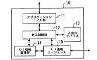
図7はユーザインタフェース部の構成例を示すブロック図である。ユーザインタフェース部10はアプリケーションと通信して印刷するドキュメント情報を得るためのアプリケーションインタフェース(I/F)部11と、ユーザインタフェース情報全体を制御する表示制御部12と、ディスプレイやキーボード、マウスなどの入出力デバイス13と、印刷するためのユーザインタフェース(UI)情報をあらかじめ蓄積しておくUI情報蓄積部14と、指示した内容や表示した内容をコントローラ20と通信するUI通信エージェント15とから構成される。 FIG. 7 is a block diagram illustrating a configuration example of the user interface unit. The
表示制御部12はアプリケーションインタフェース部11から印刷情報とデータとを入手し、UI情報蓄積部14から印刷に必要なユーザインタフェース情報を取り出し、入出力デバイス13のディスプレイに表示する。 The
一方、コントローラ20では、再構成制御部241がマーキング装置30からプロトコルIDとその内容モジュールを入手し、そのIDタイプを検出する。IDタイプは制御部23に送られ、プロトコルIDタイプとユーザインタフェース部10のバージョンとの対応が制御部23でチェックされる。制御部23はユーザインタフェース部10のUI通信エージェント15と通信する。UI通信エージェント15は再構成インタフェース部24を経由して入手したプロトコルIDを問い合わせる。次いで、UI通信エージェント15は表示制御部12に問い合わせ、表示制御部12が現在入出力デバイス13のディスプレイで表示しているユーザインタフェース内容を、UI情報蓄積部14のどの情報を使用しているかで認識する。制御部23は送られてきたプロトコルIDとUI情報蓄積部14から得たIDとを比較し、マッチしているかどうかをチェツクする。バージョンがマッチすれば、通信に問題はないと判断する。もし、問題があると、制御部23はユーザインタフェース部10に通知し、ユーザインタフェース部10は別のマッチするモジュールをダウンロードして持ってくるか、一部のユーザインタフェースソフトを変更する。マーキング装置30にプロトコルID情報がない場合は制御部23に要求し、制御部23はユーザインタフェース部10へ要求し、ユーザインタフェース部10でマッチしたプロトコルIDとそのプロトコル内容モジュールをUI通信エージェント15が転送する。 On the other hand, in the
プロトコル内容モジュールには、マーキング装置30を外部から制御やモニタするために必要なすべてのコマンド、ステータス情報が含まれている。管理情報ベース(MIB:Management Information Base)などの標準化でサポートする機能をユーザインタフェース部10からSNMP(Simple Network Management Protocol)プロトコルなどでコントローラ20に問い合わせが来る。実際のマーキング装置30で記述されるコマンドやステータスは標準的な機能のほかにデバイスの詳細な状況を問い合わせたり、設定できたりする。そのため、コントローラ20とマーキング装置30との間でやりとりするコマンドやステータスは多くのパラメータを含み、パラメータはそのマーキング装置30に特有であり、機器が代わるとそのパラメータの示す位置や数字の意味が異なる。 The protocol content module includes all commands and status information necessary for controlling and monitoring the marking
ここで、コマンドやステータス情報の意味を双方向にデコード処理するプロトコルデコーダ248の構成例について説明する。
図8はコントローラ内のプロトコルデコーダの構成例を示すブロック図である。プロトコルデコーダ248は制御部23がコマンドを出す系とそれに応答してステータスを受ける系とからなっている。コマンドを出す系はシリアルパラレル変換部2481、アドレス生成部2482、コマンド参照テーブル2483、通信データ生成部2484、およびパラレルシリアル変換部2485を有し、ステータスを受ける系はシリアルパラレル変換部2481a、アドレス生成部2482a、ステータス参照テーブル2486、通信データ生成部2484a、およびパラレルシリアル変換部2485aを有している。アドレス生成部2482、コマンド参照テーブル2483、通信データ生成部2484、アドレス生成部2482a、ステータス参照テーブル2486、および通信データ生成部2484aはFPGAによって構成され、それぞれ再構成制御部241に接続されて再構成可能なように制御される。また、展開処理部22でのエラー処理に備えて、アドレス生成部2482からステータス参照テーブル2486を介して通信データ生成部2484aへ進む系もある。Here, a configuration example of the
FIG. 8 is a block diagram showing a configuration example of a protocol decoder in the controller. The
以上の構成に従って、ユーザインタフェース部10、コントローラ20およびマーキング装置30における通信の流れを以下に示す。
まず、ユーザインタフェース部10で指示された印刷指示はUI通信エージェント15からコントローラ20の制御部23を通してシリアル伝送方式で送られてくる。シリアル伝送は一般的にUART(Universal Asynchronous Receiver−Transmitter)またはUSBなどで代表される。シリアル情報はシリアルパラレル変換部2481でパラレル情報に変換される。たとえばコマンド列“Size A4、SEL、S”の印刷指示が送られてきたとすると、アドレス生成部2482はコマンド参照テーブル2483を参照する。参照では、コマンド列の最初の文字列から、“Size”の参照先頭アドレスが0400(hex)であるとすると、第1パラメータの“A4”、第2パラメータの“SEL”、第3パラメータの“S”から参照テーブルの相対アドレスを計算し、0400(hex)+それぞれの相対アドレスからテーブルの値を順に取り出し、通信データ生成部2484で同じ意味であるが記述された内容の異なる新たなコマンド列を生成する。ユーザインタフェース部10から送られたコマンドが文字列を使用しているのに対し、新たなコマンド列は数字列となる。数字列は制御するコンピュータが解析しやすく、同じ処理速度を要求された場合、安価なCPUを使用できる。通信データ生成部2484はパラレルシリアル変換部2485から通信I/F部244を経由してマーキング装置30へ送られる。The flow of communication in the
First, a print instruction instructed by the
マーキング装置30がステータスをユーザインタフェース部10へ返す流れでは、まず、マーキング装置30から通信I/F部244を経由してシリアル伝送方式のステータス信号が送られてくる。シリアル情報はシリアルパラレル変換部2481aでパラレル情報に変換される。変換の結果が、たとえばステータス列“1121、08、11、12”であるとする。アドレス生成部2482aはステータス参照テーブル2486を参照する。参照はステータス列の数字列から、最初の“1121”を取り出し、参照アドレス先頭を計算する。たとえば0800(hex)とすると、第1パラメータの“08”、第2パラメータの“11”、第3パラメータの“12”からステータス参照テーブル2486の相対アドレスを計算し、0800(hex)+それぞれの相対アドレスからテーブルの値を順に取り出し、通信データ生成部2484aで同じ意味であるが記述された内容の異なる新たな文字列で構成されたステータス列を生成する。このステータス列はたとえば“Size、A4、SEL、Empty”であるとすると、この例では要求されたA4サイズの短辺送りの用紙は空であるとの返答を返している。このようにして、マーキング装置30から送られた数字列は文字列に変換され、ユーザインタフェース部10でダイレクトに表示しやすい情報に直される。 In the flow in which the marking
たとえばマーキング装置30に故障箇所があり、印刷できない場合はマーキング装置30からは詳細な情報が出されるが、ユーザインタフェース部10が一般の印刷ユーザだった場合、装置が正常かどうかの問い合わせに対して、正常であれば正常と返せばよい。すなわち、故障の場合はプロトコルデコーダとして“Broken”、または“Fatal Error”と返せばよい。一方、ユーザインタフェース部10が装置管理者だった時は、異常があればどの部品が異常なのか返事を返すために詳しい情報としてデコードする。たとえば図3に示したように半導体レーザー走査装置、感光体、現像機、定着機など多くのモジュールから構成されていている場合、ステータスはそれぞれのモジュールが正常かどうか伝えてくる。そのためコントローラ20に送られるステータスは装置を構成する各ユニットごとに、たとえば半導体レーザー走査装置ではその中のレンズ3121やポリゴンミラー3122、同期センサ、レーザー素子などが正常に動作中かの問い合わせに対して返事を返す。一つのユニットでは、多くの部品から構成されていて、それぞれの状態を返事として返す。たとえばユーザインタフェース部10から“Error、?”と送られると、同じルートでマーキング装置30へ送られ、マーキング装置30からは“0875、15、28、99”が返され、半導体レーザー走査装置のレンズとミラーの不具合というような詳細情報がプロトコルデコーダ248でデコードされる。ユーザインタフェース部10が一般ユーザなのか管理者なのかはUI通信エージェント15のヘッダ情報でどちらの問い合わせかは区別できる。 For example, if the marking
通信する情報全般を上げる一般印刷の基本モードの印刷指示では、プリンタ名称、アドレス、サポートするファイル形式、出力色、原稿サイズ、出力用紙サイズであり、基本モードの状態モードでは、電源、動作、エラー、優先順位、キャンセルなどである。応用印刷指示モードとして拡大縮小、回転、Nアップ、余白付与、ページ揃えなどがある。 In general mode printing instructions for general printing that raises the overall information to be communicated, it is the printer name, address, supported file format, output color, document size, output paper size. In basic mode status mode, power, operation, error , Priority, cancellation, etc. Application print instruction modes include enlargement / reduction, rotation, N-up, margin addition, page alignment, and the like.
管理者モードは大きく分けて設定管理、状態障害管理、利用状況管理がある。設定管理は使用部門やユーザごとのアクセス設定や管理をして、費用管理なども行う。状態障害管理は最も使用頻度の高いモードで、プリンタを構成するモジュール単位にエラーが無いか、消耗品が無くなっていないか、メンテナンスの時期に来ていないかどうかのチェックおよびユーザからのプリントエラー原因チェック、エラー発生したプリントジョブの修復管理などを行う。利用状況管理はプリントジョブモニタなどで日々どの程度プリンタが稼働しているかチェックするなどである。 The administrator mode is roughly divided into setting management, status failure management, and usage status management. The setting management performs access setting and management for each department and user, and also manages expenses. Status failure management is the most frequently used mode, and checks whether there are no errors in each module module, whether consumables have been exhausted, or the maintenance time has come, and causes of print errors from users Performs check management and repair management of errored print jobs. Usage status management is to check how much the printer is operating every day with a print job monitor or the like.
マーキング装置30とユーザインタフェース部10との通信を説明してきたが、通信がスムーズにいかない原因にコントローラ20が絡むことがある。マーキング装置30では、同じA4サイズの用紙をサポートしていても、画像再現範囲は同じではない。ある装置は297mm、210mm最大に再現可能であるが、別の装置では回り3mmに画像抜けが発生する。その場合は同じ印刷データでも一方は正常に出力されるが、他方は像がわずかであるが欠落する。欠落する場合にはあらかじめユーザインタフェース部10にウォーニングを上げる。マーキング装置30のデバイス特性は通信I/F部244経由で制御部23に渡され、その中に像再現範囲が規定されている。 Although the communication between the marking
また、展開処理部22で処理した結果、アピアランスエラーが発生する印刷データを検出した場合には、その時点で展開処理部22は制御部23にエラー情報をシリアル伝送の数字列で渡し、制御部23はその数字列を再構成インタフェース部24のプロトコルデコーダ248に渡す。プロトコルデコーダ248では、その数字列を一点鎖線の矢印で示したように、シリアルパラレル変換部2481およびアドレス生成部2482を経由してステータス参照テーブル2486へ送られる。ここで別の文字列にデコードされたエラーメッセージは通信データ生成部2484aで通信データに直され、パラレルシリアル変換部2485aでシリアル情報に変換され、再度制御部23、ユーザインタフェース部10に戻され、入出力デバイス13のディスプレイに像が欠ける部分を情報として表示する。これに対し、ユーザは原稿を小さくするか、別のマーキング装置で印刷するようにすることで、正常な印刷が可能になる。参照テーブルなどのハードウェアは単純にするために再構成インタフェース部24に置いているが、制御部23の内部に同様の構能を設置することでもよい。 If print data that causes an appearance error is detected as a result of processing by the
以上の実施の形態では、コントローラ20に1種類のマーキング装置を接続する形式で説明してきたが、再構成インタフェース部を含むコントローラ20は複数のマーキング装置でも同様の効果を発揮する。 Although the above embodiment has been described in the form of connecting one type of marking device to the
図9は複数のマーキング装置を含む印刷処理システムの構成を示すブロック図である。図9において、図2に示した要素と同じ構成要素には同じ符号を付してその詳細は省略する。 FIG. 9 is a block diagram showing a configuration of a print processing system including a plurality of marking devices. In FIG. 9, the same components as those shown in FIG.
コントローラ20の再構成インタフェース部24はn個のマーキング装置30a〜30nが接続されている。これらのマーキング装置30a〜30nはそれぞれたとえば図6に示したような各種タイプの出力部を備えたものである。したがって、再構成インタフェース部24は印刷に使用するマーキング装置に応じてインタフェースが変更されることになる。 The
ユーザインタフェース部10がマーキング装置を特定せずにコントローラ20ヘ印刷データを送る場合は、制御部23がまずマーキング装置を適当に選択する。ここでは、たとえばマーキング装置30bを選択したとすれば、再構成インタフェース部24はそのマーキング装置30bから情報を入手して各種設定処理を行う。そして、制御部23がマーキング装置30bの通信プロトコルIDをユーザインタフェース部10に伝えることによってプリント処理が可能になる。 When the
以上、本発明をその好適な実施の形態について詳述したが、本発明はこれらの実施の形態に限定されるものではない。たとえば、上述のコントローラは再構成インタフェース部24を1つしか備えていないが、再構成インタフェースのみを2つまたはそれ以上サポートするようにしてもよく、その場合は、多くのユーザが同時に別々のマーキング装置に印刷要求してきたときにも、個々にかつ高速に対応できる機構となる。 As mentioned above, although this invention was explained in full detail about the suitable embodiment, this invention is not limited to these embodiment. For example, although the controller described above has only one
また、マーキング装置として、単に印刷処理をするだけではなく、印刷後に製本やステープラ止めなどを行う機能を備えたものもあり、このような機能に関する情報も出力部制御管理部に保存されている。この場合、マーキング装置のデバイス情報としてすべてのプロトコルデコード情報を印刷処理装置にアップロードするのではなく、ユーザインタフェース部の持つ機能に応じて必要な情報、すなわち、少なくともプリント情報デコード情報および装置状態監視デコード情報だけをアップロードする。 In addition, some marking apparatuses have a function of performing bookbinding or stapler stop after printing as well as printing processing, and information on such functions is also stored in the output unit control management unit. In this case, instead of uploading all protocol decode information as device information of the marking device to the print processing device, information required according to the function of the user interface unit, that is, at least print information decode information and device state monitoring decode Upload information only.
1 印刷処理装置
1a 印刷データ入力手段
1b 印刷データ展開処理手段
1c 再構成インタフェース手段
2 マーキング装置
10 ユーザインタフェース部
20 コントローラ
21 印刷データ入力部
22 展開処理部
23 制御部
24 再構成インタフェース部
30 マーキング装置
31 出力部
32 出力部制御管理部DESCRIPTION OF SYMBOLS 1
Claims (4)
Translated fromJapanese前記ユーザインタフェース部で表示されるユーザインタフェースを前記マーキング装置と整合するように変更制御することを特徴とする印刷処理方法。In a printing processing method for performing device status monitoring or printing instruction for the marking device at a user interface unit with respect to the marking device,
A print processing method comprising: changing and controlling a user interface displayed on the user interface unit so as to be consistent with the marking device.
前記ユーザインタフェース部で表示されるユーザインタフェースを前記マーキング装置と整合するように変更制御する制御装置を備えたことを特徴とする印刷処理システム。In a print processing system that performs device status monitoring or a print instruction for the marking device at a user interface unit with respect to the marking device,
A print processing system comprising: a control device that controls to change a user interface displayed on the user interface unit so as to match the marking device.
Priority Applications (1)
| Application Number | Priority Date | Filing Date | Title |
|---|---|---|---|
| JP2005158091AJP2005267662A (en) | 2005-05-30 | 2005-05-30 | Print processing method and print processing system |
Applications Claiming Priority (1)
| Application Number | Priority Date | Filing Date | Title |
|---|---|---|---|
| JP2005158091AJP2005267662A (en) | 2005-05-30 | 2005-05-30 | Print processing method and print processing system |
Related Parent Applications (1)
| Application Number | Title | Priority Date | Filing Date |
|---|---|---|---|
| JP31022597ADivisionJP3700351B2 (en) | 1997-11-12 | 1997-11-12 | Print processing device |
Publications (1)
| Publication Number | Publication Date |
|---|---|
| JP2005267662Atrue JP2005267662A (en) | 2005-09-29 |
Family
ID=35092071
Family Applications (1)
| Application Number | Title | Priority Date | Filing Date |
|---|---|---|---|
| JP2005158091APendingJP2005267662A (en) | 2005-05-30 | 2005-05-30 | Print processing method and print processing system |
Country Status (1)
| Country | Link |
|---|---|
| JP (1) | JP2005267662A (en) |
Citations (6)
| Publication number | Priority date | Publication date | Assignee | Title |
|---|---|---|---|---|
| JPH06234257A (en)* | 1993-02-12 | 1994-08-23 | Canon Inc | Printer control method and apparatus |
| JPH07199077A (en)* | 1993-12-29 | 1995-08-04 | Olympus Optical Co Ltd | Microscopic system |
| JPH0818723A (en)* | 1994-06-29 | 1996-01-19 | Toshiba Corp | Multifunction multifunction machine |
| JPH0926867A (en)* | 1995-05-30 | 1997-01-28 | Canon Inc | User interface display method |
| JPH0946330A (en)* | 1995-07-28 | 1997-02-14 | Toshiba Corp | E-mail encryption device and e-mail transfer device |
| JPH09258919A (en)* | 1996-03-19 | 1997-10-03 | Ricoh Co Ltd | Printer device |
- 2005
- 2005-05-30JPJP2005158091Apatent/JP2005267662A/enactivePending
Patent Citations (6)
| Publication number | Priority date | Publication date | Assignee | Title |
|---|---|---|---|---|
| JPH06234257A (en)* | 1993-02-12 | 1994-08-23 | Canon Inc | Printer control method and apparatus |
| JPH07199077A (en)* | 1993-12-29 | 1995-08-04 | Olympus Optical Co Ltd | Microscopic system |
| JPH0818723A (en)* | 1994-06-29 | 1996-01-19 | Toshiba Corp | Multifunction multifunction machine |
| JPH0926867A (en)* | 1995-05-30 | 1997-01-28 | Canon Inc | User interface display method |
| JPH0946330A (en)* | 1995-07-28 | 1997-02-14 | Toshiba Corp | E-mail encryption device and e-mail transfer device |
| JPH09258919A (en)* | 1996-03-19 | 1997-10-03 | Ricoh Co Ltd | Printer device |
Similar Documents
| Publication | Publication Date | Title |
|---|---|---|
| JP3826038B2 (en) | Printing system, printing method therefor, and printing apparatus | |
| US8472043B2 (en) | Information processing apparatus and its control method for managing distributed processing | |
| JP4529148B2 (en) | Print control program, print control apparatus, image forming apparatus, and print control method | |
| US7382484B2 (en) | Information processing apparatus and its control method | |
| CN104219422A (en) | Color adjusting system, and color adjusting method | |
| US20100123926A1 (en) | Image forming apparatus and control method thereof | |
| JP2008258845A (en) | Color image processing system and method | |
| JP4661932B2 (en) | Image forming apparatus and image forming control program | |
| US8264744B2 (en) | Image processing apparatus, image processing method, and program to execute image processing method | |
| JP4418642B2 (en) | HOST DEVICE, PRINTING DEVICE, PRINTING SYSTEM HAVING THEM, PRINT CONTROL METHOD, AND PROGRAM THEREOF | |
| JPH10173947A (en) | Image processing apparatus and method | |
| JP3700351B2 (en) | Print processing device | |
| JP2005349755A (en) | Color printer | |
| JPH1065919A (en) | Image forming device and image processing unit | |
| JP2005022298A (en) | Printing device | |
| US20050275883A1 (en) | Information processing apparatus and its control method | |
| JP2016213646A (en) | Print image generating device, color conversion control program and color conversion control method | |
| JPH11105371A (en) | Print processor | |
| JP2005267662A (en) | Print processing method and print processing system | |
| JP2006106473A (en) | Image processing device | |
| JP4479289B2 (en) | Printing control apparatus and method, data expansion apparatus | |
| JP5389096B2 (en) | Apparatus and control method thereof | |
| JP6504464B2 (en) | PRINT CONTROL DEVICE, PRINT CONTROL PROGRAM, AND PRINT CONTROL METHOD | |
| JP4663140B2 (en) | Data processing apparatus and method, storage medium and program | |
| JP2006235813A (en) | Printing system |
Legal Events
| Date | Code | Title | Description |
|---|---|---|---|
| A977 | Report on retrieval | Free format text:JAPANESE INTERMEDIATE CODE: A971007 Effective date:20080221 | |
| A131 | Notification of reasons for refusal | Free format text:JAPANESE INTERMEDIATE CODE: A131 Effective date:20080226 | |
| A521 | Written amendment | Free format text:JAPANESE INTERMEDIATE CODE: A523 Effective date:20080423 | |
| A02 | Decision of refusal | Free format text:JAPANESE INTERMEDIATE CODE: A02 Effective date:20080520 |