JP2005266718A - Microscopic image photographing system - Google Patents
Microscopic image photographing systemDownload PDFInfo
- Publication number
- JP2005266718A JP2005266718AJP2004083240AJP2004083240AJP2005266718AJP 2005266718 AJP2005266718 AJP 2005266718AJP 2004083240 AJP2004083240 AJP 2004083240AJP 2004083240 AJP2004083240 AJP 2004083240AJP 2005266718 AJP2005266718 AJP 2005266718A
- Authority
- JP
- Japan
- Prior art keywords
- image
- parent
- magnification
- child
- sub
- Prior art date
- Legal status (The legal status is an assumption and is not a legal conclusion. Google has not performed a legal analysis and makes no representation as to the accuracy of the status listed.)
- Pending
Links
Images


Landscapes
- Microscoopes, Condenser (AREA)
- Studio Devices (AREA)
Abstract
Description
Translated fromJapanese本発明は、顕微鏡画像撮影装置に係わり、特に病理診断学の教材用に用いられる顕微鏡ディジタル画像の撮像装置に関する。 The present invention relates to a microscope image photographing apparatus, and more particularly to a microscope digital image imaging apparatus used for teaching materials for pathological diagnosis.
顕微鏡画像をディジタル化して観察する方法として、次のものがある。特許文献1では、顕微鏡を用いて標本の観察をする場合、一度に観察できる範囲は主に対物レンズの倍率によって決定され、対物レンズが高倍率になると観察範囲が狭くなるが、その分高精細な画像を取得できることを利用して、この高倍率の対物における高精細な顕微鏡画像の画像を貼り合わせることにより、高解像および広画角な画像を形成する顕微鏡装置が提案されている。 There are the following methods for digitizing and observing a microscope image. In Patent Document 1, when observing a specimen using a microscope, the range that can be observed at a time is mainly determined by the magnification of the objective lens, and when the objective lens becomes high magnification, the observation range becomes narrower. A microscope apparatus has been proposed that forms a high-resolution and wide-angle image by combining high-definition microscope image images of this high-magnification objective using the ability to acquire a simple image.
また、特許文献2では、顕微鏡の観察手順について、現在の観察画像を親画像として、この親画像の一部について対物の倍率を上げて取り込んだ画像を子画像とし、親子関係情報を作成し、この親子関係に基づいて、観察画像をツリー構造図で表示し、観察過程を残す方法が提案されている。 Further, in Patent Document 2, regarding the observation procedure of the microscope, the current observation image is used as a parent image, an image obtained by increasing the objective magnification for a part of the parent image is used as a child image, and parent-child relationship information is created. Based on this parent-child relationship, a method of displaying an observation image in a tree structure diagram and leaving an observation process has been proposed.
上記の例のように、顕微鏡画像をディジタル化することにより、病理診断学の教材として利用することが可能であり、ディジタル画像のモニタ観察により、同一の臓器ブロックから複数枚の切り出し・スライドガラスの作成をする必要がなくなり、切り出し位置が異なることによる標本のばらつきをなくすことができる。
しかしながら、前述した従来例のうち、特許文献1では、対物レンズ倍率に応じたオーバーラップも考慮した取り込み位置制御はするが、標本の存在しない位置の画像の撮影や、標本がある位置でも診断には不要な位置までも撮影してしまい、無駄な時間・無駄な記録容量を必要とすると問題点があった。 However, among the above-described conventional examples, in Patent Document 1, capture position control is performed in consideration of overlap according to the objective lens magnification. In this case, there is a problem in that even unnecessary positions are photographed, and useless time and useless recording capacity are required.
また、特許文献2では、観察手順を親子情報として管理することにより任意の画像を迅速に且つ容易に選択、表示することができ、更には各画像に様々なコメントや印を付けることで、観察やその後のレポート等の作成が容易することができることが記載されているが、弱拡大倍率での解像度が不足しているという問題があった。 Further, in Patent Document 2, any image can be selected and displayed quickly and easily by managing the observation procedure as parent-child information. Furthermore, various comments and marks can be attached to each image for observation. However, there is a problem that the resolution at the low magnification is insufficient.
上記の課題に鑑み、本発明は、特に病理診断学の教材に使用可能な必要最小限の領域かつ高精細な顕微鏡ディジタル画像撮影可能な顕微鏡画像撮影システム、顕微鏡画像撮影方法、及び顕微鏡画像撮影プログラムを提供する。 In view of the above problems, the present invention provides a microscope image photographing system, a microscope image photographing method, and a microscope image photographing program capable of photographing a minimum necessary area and a high-definition digital microscope image that can be used particularly as a teaching material for pathological diagnosis. I will provide a.
上記課題は、特許請求の範囲の請求項1に記載の発明によれば、観察する標本の所望の位置を所望の倍率で撮影して画像として取り込み可能な顕微鏡画像撮影システムにおいて、低倍率で取り込んだ前記画像を親画像とし、該親画像中の一部の領域に対応する前記標本の部位を倍率を上げて取り込んだ画像を子画像として、順次これらの取り込まれた画像間の親子関係情報を記憶する記憶手段と、前記子画像のうち所定の子画像に対応する所定の親画像である対象親画像を前記親子関係情報に基づいて決定する対象親画像決定手段と、前記対象親画像の座標情報と所定の倍率情報とに基づいて、該対象親画像の撮影領域を分割した小区画を算出する小区画算出手段と、前記小区画算出手段により算出された小区画に対応する前記標本の部位を前記所定の倍率情報の示す倍率により順次撮影する小区画撮影手段と、前記小区画撮影手段により撮影した複数の前記小区画の画像を連続した一枚の画像に合成する小区画合成手段と、を備えることを特徴とする顕微鏡画像撮影システムを提供することによって達成できる。 According to the first aspect of the present invention, in the microscope image capturing system capable of capturing a desired position of a specimen to be observed at a desired magnification and capturing it as an image, capturing at a low magnification. The image is a parent image, and an image obtained by increasing the magnification of the part of the specimen corresponding to a part of the parent image is used as a child image, and parent-child relationship information between these captured images is sequentially obtained. Storage means for storing; target parent image determination means for determining a target parent image that is a predetermined parent image corresponding to a predetermined child image of the child images based on the parent-child relationship information; and coordinates of the target parent image Based on the information and predetermined magnification information, a small section calculating means for calculating a small section obtained by dividing the imaging region of the target parent image, and a part of the sample corresponding to the small section calculated by the small section calculating means The A small section photographing means for sequentially photographing at a magnification indicated by the predetermined magnification information; and a small section combining means for combining the images of the plurality of small sections photographed by the small section photographing means into a single continuous image. This can be achieved by providing a microscope image capturing system characterized by comprising:
このように構成することによって、標本画像のうち必要な箇所のみを高精細な画像とすることができる。
上記課題は、特許請求の範囲の請求項2に記載の発明によれば、観察する標本の所望の位置を所望の倍率で撮影して画像として取り込み可能な顕微鏡画像撮影システムにおいて、低倍率で取り込んだ前記画像を親画像とし、該親画像中の一部の領域に対応する前記標本の部位を倍率を上げて取り込んだ画像を子画像として、順次これらの取り込まれた画像間の親子関係情報を記憶する記憶手段と、前記子画像のうち所定の子画像の注目領域の座標を読み出す読み出し手段と、前記座標を含む所定領域を表す情報と所定の倍率情報とに基づいて、該所定領域を分割した小区画を算出する小区画算出手段と、前記小区画算出手段により算出された小区画に対応する前記標本の部位を前記所定の倍率情報の示す倍率により順次撮影する小区画撮影手段と、前記小区画撮影手段により撮影した複数の前記小区画の画像を連続した一枚の画像に合成する小区画合成手段と、を備えることを特徴とする顕微鏡画像撮影システムを提供することによって達成できる。By configuring in this way, only a necessary portion of the sample image can be made a high-definition image.
According to the second aspect of the present invention, in the microscope image capturing system capable of capturing a desired position of a specimen to be observed at a desired magnification and capturing it as an image, capturing at a low magnification. The image is a parent image, and an image obtained by increasing the magnification of the part of the specimen corresponding to a part of the parent image is used as a child image, and parent-child relationship information between these captured images is sequentially obtained. The predetermined area is divided based on storage means for storing, reading means for reading out the coordinates of the attention area of a predetermined child image of the child images, information indicating the predetermined area including the coordinates, and predetermined magnification information A small section calculating means for calculating the small section, and a small section photographing hand for sequentially photographing the part of the sample corresponding to the small section calculated by the small section calculating means at a magnification indicated by the predetermined magnification information And a small-compartment synthesizing unit that synthesizes a plurality of images of the small sections photographed by the small-section photographing means into a single continuous image. it can.
このように構成することによって、標本画像のうち必要な箇所のみを高精細な画像とすることができる。
上記課題は、特許請求の範囲の請求項3に記載の発明によれば、前記顕微鏡画像撮影システムは、さらに、前記小区画合成手段により合成した画像である合成画像を前記対象親画像に関連付ける合成画像関連付け手段を備えることを特徴とする請求項1、又は2に記載の顕微鏡画像撮影システムを提供することによって達成できる。By configuring in this way, only a necessary portion of the sample image can be made a high-definition image.
According to the third aspect of the present invention, the microscope image capturing system further includes a composition for associating a synthesized image, which is an image synthesized by the subsection synthesizing unit, with the target parent image. It can be achieved by providing the microscope image photographing system according to claim 1 or 2, further comprising an image association means.
このように構成することによって、作成した高精細な画像を全体画像に関連付けて、これらの画像間で親子関係を形成することができる。
上記課題は、特許請求の範囲の請求項4に記載の発明によれば、前記顕微鏡画像撮影システムは、さらに、前記合成画像の表示倍率を変更する表示倍率変更手段を備えることを特徴とする請求項3に記載の顕微鏡画像撮影システムを提供することによって達成できる。With this configuration, the created high-definition image can be associated with the entire image, and a parent-child relationship can be formed between these images.
According to the invention described in claim 4, the microscope image capturing system further includes display magnification changing means for changing a display magnification of the composite image. This can be achieved by providing the microscope image capturing system according to Item 3.
このように構成することによって、高精細画像自体を拡大・縮小することができる。
上記課題は、特許請求の範囲の請求項5に記載の発明によれば、前記顕微鏡画像撮影システムは、さらに、前記標本の撮影に使用される対物レンズと前記標本との間の光軸方向の相対位置を変化させる位置変化手段を備えることを特徴とする請求項1、又は2に記載の顕微鏡画像撮影システムを提供することによって達成できる。With this configuration, the high-definition image itself can be enlarged or reduced.
According to the invention described in claim 5 of the present invention, the microscope image photographing system further includes an objective lens used for photographing the specimen and an optical axis direction between the specimen. It can be achieved by providing a microscope image photographing system according to claim 1 or 2, further comprising position changing means for changing a relative position.
このように構成することによって、撮影面に対して例えば垂直方向(ΔZ)のみ異なる同一領域の高精細画像を複数取得することができる。
上記課題は、特許請求の範囲の請求項6に記載の発明によれば、前記顕微鏡画像撮影システムは、さらに、1つ又は複数のクライアント装置を備え、前記クライアント装置から当該前記顕微鏡画像撮影システムを制御することを特徴とする請求項1〜5のいずれか1項に記載の顕微鏡画像撮影システムを提供することによって達成できる。With this configuration, it is possible to acquire a plurality of high-definition images in the same region that differ only in the vertical direction (ΔZ), for example, with respect to the imaging surface.
According to the invention described in claim 6, the microscope image capturing system further includes one or a plurality of client devices, and the microscope image capturing system is transferred from the client device. Control can be achieved by providing the microscope image photographing system according to any one of claims 1 to 5.
このように構成することによって、各クライアント装置から、標本画像のうち必要な箇所のみを高精細な画像として得ることができる。
上記課題は、特許請求の範囲の請求項7に記載の発明によれば、観察する標本の所望の位置を所望の倍率で撮影して画像として取り込む顕微鏡画像撮影方法において、低倍率で取り込んだ前記画像を親画像とし、該親画像中の一部の領域に対応する前記標本の部位を倍率を上げて取り込んだ画像を子画像として、順次これらの取り込まれた画像間の親子関係情報を記憶し、前記子画像のうち所定の子画像に対応する所定の親画像である対象親画像を前記親子関係情報に基づいて決定し、前記対象親画像の座標情報と所定の倍率情報とに基づいて、該対象親画像の撮影領域を分割した小区画を算出し、前記小区画算出手段により算出された小区画に対応する前記標本の部位を前記所定の倍率情報の示す倍率により順次撮影し、前記小区画撮影手段により撮影した複数の前記小区画の画像を連続した一枚の画像に合成することを特徴とする顕微鏡画像撮影方法を提供することによって達成できる。With this configuration, it is possible to obtain only a necessary portion of the specimen image as a high-definition image from each client device.
According to the invention described in claim 7 of the present invention, the above-mentioned problem is that the microscope image capturing method that captures a desired position of a specimen to be observed at a desired magnification and captures it as an image is captured at a low magnification. An image is a parent image, and an image acquired by increasing the magnification of the part of the sample corresponding to a part of the region in the parent image is used as a child image, and parent-child relationship information between these acquired images is sequentially stored. Determining a target parent image that is a predetermined parent image corresponding to a predetermined child image among the child images based on the parent-child relationship information, and based on the coordinate information of the target parent image and predetermined magnification information, A small section obtained by dividing the imaging region of the target parent image is calculated, and the part of the sample corresponding to the small section calculated by the small section calculating unit is sequentially captured at a magnification indicated by the predetermined magnification information, and the small section is captured. Section shooting hand It can be achieved by providing a microscopic image capturing method characterized by synthesizing a single image with images continuous of the plurality of small sections taken by.
このように構成することによって、標本画像のうち必要な箇所のみを高精細な画像とすることができる。
上記課題は、特許請求の範囲の請求項8に記載の発明によれば、観察する標本の所望の位置を所望の倍率で撮影して画像として取り込むために、コンピュータに実行させるための顕微鏡画像撮影プログラムにおいて、低倍率で取り込んだ前記画像を親画像とし、該親画像中の一部の領域に対応する前記標本の部位を倍率を上げて取り込んだ画像を子画像として、順次これらの取り込まれた画像間の親子関係情報を記憶する記憶処理と、前記子画像のうち所定の子画像に対応する所定の親画像である対象親画像を前記親子関係情報に基づいて決定する対象親画像決定処理と、前記対象親画像の座標情報と所定の倍率情報とに基づいて、該対象親画像の撮影領域を分割した小区画を算出する小区画算出処理と、前記小区画算出処理により算出された小区画に対応する前記標本の部位を前記所定の倍率情報の示す倍率により順次撮影する小区画撮影処理と、前記小区画撮影処理により撮影した複数の前記小区画の画像を連続した一枚の画像に合成する小区画合成処理と、を、コンピュータに実行させるための顕微鏡画像撮影プログラムを提供することによって達成できる。By configuring in this way, only a necessary portion of the sample image can be made a high-definition image.
According to the invention described in claim 8, the above-described problem is a microscope image photographing for causing a computer to execute photographing at a desired magnification and capturing an image as a desired position of a specimen to be observed. In the program, the image captured at a low magnification is used as a parent image, and the portion of the specimen corresponding to a part of the region in the parent image is captured as a child image. Storage processing for storing parent-child relationship information between images, and target parent image determination processing for determining a target parent image that is a predetermined parent image corresponding to a predetermined child image among the child images based on the parent-child relationship information; Based on the coordinate information of the target parent image and predetermined magnification information, a small section calculation process for calculating a small section obtained by dividing the shooting region of the target parent image and the small section calculation process are used. A single image in which the image of the plurality of small sections photographed by the small section photographing process and the small section photographing process sequentially photographing the portion of the specimen corresponding to the small section at the magnification indicated by the predetermined magnification information is continuous. By providing a microscopic image photographing program for causing a computer to execute the sub-compartment combining processing to be combined with the computer.
このように構成することによって、標本画像のうち必要な箇所のみを高精細な画像とすることができる。 By configuring in this way, only a necessary portion of the sample image can be made a high-definition image.
本発明によれば、広画角かつ高精細の顕微鏡画像を効率良く撮影・構築し、画像取り込み時間および画像記録容量の削減を図った顕微鏡画像撮影装置を提供でき、病理診断学の教材や病理医間のカンファレンス用としても必要充分な画質の画像を提供することができる。 According to the present invention, it is possible to provide a microscopic image photographing apparatus that efficiently captures and constructs a wide-angle and high-definition microscopic image and reduces the image capturing time and the image recording capacity. It is possible to provide necessary and sufficient image quality for conferences between doctors.
<第1の実施形態>
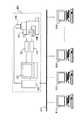
図1は、本実施形態における顕微鏡画像撮影装置の全体構成を示す図である。顕微鏡画像撮影装置100は、顕微鏡107、コンピュータ120、モニタ103、顕微鏡コントローラ105、ステージコントローラ106から構成される。顕微鏡107には、図示しない対物切り替え用電動レボルバ、光量調節、絞り調整、光路切り替え、準焦部制御等の電動機能を備えており、さらに電動ステージ108と顕微鏡像用のTVカメラ109を備えている。<First Embodiment>
FIG. 1 is a diagram illustrating an overall configuration of a microscope image photographing apparatus according to the present embodiment. The microscope
この顕微鏡を制御する顕微鏡コントローラ105は、コンピュータから顕微鏡の動作命令を受け取って、顕微鏡各部のアクチュエータを動作命令通りに駆動させる駆動信号を作る。この顕微鏡コントローラ105は、顕微鏡本体107とコンピュータ120に接続されており、コンピュータ120から顕微鏡107についての所望の対物レンズ倍率、XY座標位置、Z位置、明るさ、絞り等の調整を可能にしている。 The
コンピュータ120は、CPU117、メモリ116その他モニタ表示用のディスプレイドライバ101と、TVカメラからの画像信号を取りこむ画像キャプチャ102と、顕微鏡コントローラあるいはステージコントローラと通信をする通信I/F(インターフェース)111,112と、キーボードやマウスまたはフットSW(スイッチ)等の入力装置を制御する制御ドライバ114と、大容量の記録媒体113のユニットから構成される。各々のユニットは、CPUバス110に接続されており、これらはCPU117にて制御可能となっている。 The
大容量記録媒体113は、コンピュータ120に内蔵せずに、ファイバーチャネルなどの1Gbpsを超える高速データ転送可能なインターフェースを有する外付け大容量ディスクを使用しても良い。コンピュータ120の周辺の制御機器は、キーボードあるいはマウス115が有り、コンピュータ120内のドライバ114を経由してCPUバス110と接続する。 The large-
また、コンピュータ120の制御画面表示は、ディスプレイドライバ101を介してモニタ103に表示される。コンピュータ120には、図示しない顕微鏡画像撮影用アプリケーションソフトウェアが記録媒体113に記憶されており、このソフトウェアはCPU117の制御によってメモリ116にロードされ、モニタ103上に図示しない顕微鏡撮影用操作画面を表示する。 The control screen display of the
大容量記録媒体113は、TVカメラ109からの画像信号をコンピュータ120内の画像キャプチャ102を通じて撮影した顕微鏡画像データと座標情報を含む画像付随データと共に記録可能にする。このような機器接続より操作者は、モニタ103上に表示している顕微鏡撮影用アプリケーションソフトウェア画面上をキーボードあるいはマウス115により操作し、顕微鏡107、ステージ108を制御し、顕微鏡画像撮影ができることになる。 The large-
図2は、本実施形態における画像取り込み手順のフローを示す。まず、病理診断できる指導医が診断を実施し、その観察手順を記録する(S201)。観察手順は、特許文献2に記載されているように、どのように観察したかその観察ログ(観察履歴であって、画像間の親子関係情報を含むもの)を保存し、その結果をツリー構造表示できるようにする。 FIG. 2 shows a flow of an image capturing procedure in the present embodiment. First, an instructor who can make a pathological diagnosis performs a diagnosis and records the observation procedure (S201). As described in Patent Document 2, the observation procedure is to store the observation log (observation history including information on parent-child relationship between images) as to how the observation was performed, and display the result in a tree structure Enable display.
ツリー構造の表示についてさらに説明すると、まず、観察者はプレパラートに標本をセットして、その標本を撮影し、その標本の全体画像を取り込む。そして、この全体画像をモニタ103に表示して、適当な弱拡大倍率の対物レンズの画角に相当する大きさのブロックで分割する。 The display of the tree structure will be further described. First, the observer sets a specimen on a slide, photographs the specimen, and captures the entire image of the specimen. Then, the entire image is displayed on the
次に、プレパラートを顕微鏡107の電動ステージ108に載せ換え、指定したブロックに対応する顕微鏡画像を順次取り込んでいく。これらの画像は全て大容量記憶媒体113に保存される。
こうして、全てのブロックに対応する画像が取り込まれると、コンピュータ120はブロックの枚数を基に最初のツリー構造図を作り、モニタ103に表示する(図3参照)。Next, the preparation is placed on the
When images corresponding to all the blocks are captured in this way, the
そして、インデックス画像(ツリー構造図の分岐部分や枝部分等に用いられる画像、図3でいえば四角枠で表される部分)を用いるツリー構造図を表示する際には、対応する画像を外部記憶装置から呼び出し、画素を適当に間引くことによって、画像を縮小させる。例えば、もとの画像の2×2画像分の領域を適当な1画素で代表させることにより、画像の大きさは縦横それぞれ1/2に縮小される。 When displaying a tree structure diagram using an index image (an image used for a branch part or a branch part of the tree structure diagram, a part represented by a square frame in FIG. 3), the corresponding image is externally displayed. The image is reduced by calling from the storage device and thinning out the pixels appropriately. For example, by representing a 2 × 2 image area of the original image with an appropriate one pixel, the size of the image is reduced to ½ in both vertical and horizontal directions.
本実施形態では、16×16画素の領域を1画素で代表させることにより、原画の1/16のインデックス画像をつくり、これをツリー構造図に用いた。このツリー構造図の任意のブロックあるいはインデックス画像をマウス115で選択することにより、それに対応する画像が外部記憶装置から読み出されモニタ103に再生・表示される。 In the present embodiment, an index image of 1/16 of the original image is created by representing an area of 16 × 16 pixels with one pixel, and this is used in the tree structure diagram. By selecting an arbitrary block or index image of this tree structure diagram with the
そして、観察者は任意の画像をモニタ103に表示させた後、マウス115を用いて画像上に更に拡大観察したい領域を指定できると共に、メニューを操作することにより、希望の対物レンズを選択することができる。
こうして、これらの指定が終了すると、コンピュータ120から制御信号が発せられ、電動ステージ108が所定の位置に移動し、電動対物レンズレボルバが回転して所定の対物レンズに切り替わる。そして、ピント、絞りの調節を行う。その後、観察者は、この顕微鏡画像を取り込むことができ、新たに取り込まれた画像は外部記憶装置に保存される。このようにして画像の取り込みを繰り返す毎に観察ログが記録されていき、その結果、これらの顕微鏡画像は、ツリー構造状の親子関係を構成する。Then, after displaying an arbitrary image on the
Thus, when these designations are completed, a control signal is issued from the
以上のようにして観察ログがツリー構造状に記録されていき、この観察ログの中で、最終診断に至った重要な画像または画像内の所定箇所にマーキングを施す。マーキングは、従来行われている手法で行い、例えば、最終的に診断に至るために注目した画像について、診断した医師(指導医)によりマーキングしてもよいし(例えば、当該画像を管理するデータのうち、所定のフラグを「1」にするなど)、ツリー構造のうち最も下位にある画像をマーキングするようにしてもよい。 As described above, the observation log is recorded in a tree structure, and in this observation log, marking is performed on an important image that has reached the final diagnosis or a predetermined location in the image. Marking is performed by a conventionally performed technique. For example, an image focused on to finally reach a diagnosis may be marked by a diagnosed doctor (instructor) (for example, data for managing the image) Among them, a predetermined flag may be set to “1”), and the lowest image in the tree structure may be marked.
また、キーボードやマウスの代わりにフットSW(不図示)を用いて、観察したログを引き出すトリガが取りだせるようにして、観察ログをツリー構造で保存しても良い。
次に、観察手順の中からマーキングされた重要な部分に関する座標を検出する(S202)。具体的には、指導医による診断が終了すると、所定の操作(例えば、所定のスイッチを押下する等)により、CPU117は大容量記録媒体113から上記の観察ログを読み出し、診断に至った画像、つまりマーキングした画像(以下、マーキング画像)を検出する(上記の通り、このような画像には所定のフラグがONになっているので、それを検出する)。このマーキング画像の上位の関係にある画像(親画像)のうち、所定の上位の画像(親画像)まで遡る。そして、この親画像を撮影領域として決定する(S203)。この処理については、図3で詳述する。Further, the observation log may be stored in a tree structure so that a trigger for extracting the observed log can be taken out using a foot SW (not shown) instead of a keyboard or a mouse.
Next, coordinates relating to an important portion marked from the observation procedure are detected (S202). Specifically, when the diagnosis by the instructor is completed, the CPU 117 reads the above observation log from the large-
S203において撮影位置・領域を決定後、対物レンズ倍率を高倍に設定し、指定領域内を対物レンズでの視野サイズに応じて撮影開始する(S204)。このS204では、特許文献1に記載されているように、指定領域内を複数の小区画に分割し、各小区画を高倍で順に撮影していくようにしてもよい。また、観察に使う対象レンズの倍率(高倍)を操作者が決定すると、指定された撮影領域をそのレンズの視野で分割する処理を行い、その後の1つ1つの区画を順に撮影処理していくようにしてもよい。 After determining the shooting position / area in S203, the objective lens magnification is set to a high magnification, and shooting is started in the designated area according to the field size of the objective lens (S204). In S204, as described in Patent Document 1, the designated area may be divided into a plurality of small sections, and each small section may be photographed in order at a high magnification. When the operator determines the magnification (high magnification) of the target lens to be used for observation, a process for dividing the designated imaging region by the field of view of the lens is performed, and the subsequent sections are sequentially imaged. You may do it.
このようにすることにより、現在観察している観察範囲を小区画に分割して、各小区画を現在の観察倍率よりも大きな観察倍率でそれぞれ入力できるので、高解像な顕微鏡画像を形成できる。
また、このとき、視野サイズに応じて画像の重なりを含ませて撮影しても良い。画像の重なりは、ステージ精度を考慮して決定する。この場合の処理は、特許文献1に記載されているように、標本範囲を複数の小区画に分割して小区画を入力可能な観察倍率とを決め、顕微鏡の観察倍率が小区画を入力可能な観察倍率に設定されるように顕微鏡コントローラ105に対して制御指令を与え、電動ステージ108を小区画の撮影が可能な位置へ移動させるための制御データを全小区画について作成して当該制御データをステージコントローラ106に対して制御指令として与え、大容量記憶媒体113から各小区画の画像情報を取り出して画像貼り合わせ処理を実行し複数の小区画に分割して入力した標本範囲を一枚の画像に形成する。By doing so, the observation range currently observed can be divided into small sections, and each small section can be input at an observation magnification larger than the current observation magnification, so that a high-resolution microscope image can be formed. .
At this time, images may be captured with overlapping images according to the field of view size. The overlap of images is determined in consideration of stage accuracy. In this case, as described in Patent Document 1, the specimen range is divided into a plurality of small sections, the observation magnification capable of inputting the small sections is determined, and the observation magnification of the microscope can input the small sections. A control command is given to the
このようにすることにより、目的とする画像形成範囲を、複数の小区画に分割し、視野調節手段により該区画を観察視野内に納め、画像入力装置により画像を入力し、画像蓄積手段に該画像を格納する。画像形成範囲を複数の小区画に分割する場合、X軸方向またはY軸方向に隣接する各小区画の端部画像領域が重複するように設定する。蓄積された複数枚の画像を貼り合わせ手段により繋ぎ合わせることにより、広画角な顕微鏡画像が形成される。 In this way, the target image formation range is divided into a plurality of small sections, the sections are placed in the observation field by the visual field adjusting means, the image is input by the image input device, and the image storage means is Store the image. When the image forming range is divided into a plurality of small sections, the end image areas of the respective small sections adjacent in the X-axis direction or the Y-axis direction are set to overlap. A microscope image having a wide angle of view is formed by joining the accumulated images with a pasting unit.
図3は、本実施形態における病理診断を行った結果の観察ログのツリー構造を示す。この図は、上記のS202とS203の処理を説明するものである。このツリー構造を用いて、所定の画像の重要領域を自動検出する。通常、全体像から順次倍率を上げて行き、診断に至る画像を取得するまで顕微鏡対物レンズを上げて観察を続ける。最終的に診断に至った画像にはマーキングが施されているものとする。同図では画像301(40x(倍)で撮影した画像)についてマーキングが施されている。 FIG. 3 shows a tree structure of an observation log as a result of pathological diagnosis in the present embodiment. This figure explains the processing of S202 and S203 described above. Using this tree structure, an important area of a predetermined image is automatically detected. Usually, the magnification is sequentially increased from the whole image, and the observation is continued by raising the microscope objective lens until an image leading to diagnosis is obtained. It is assumed that marking is applied to an image that finally reaches a diagnosis. In the figure, marking is applied to an image 301 (an image taken at 40x (times)).
ツリー構造上で、この高倍で観察したマーキング画像301から遡って、この診断に至った画像301の上位関係にある低倍画像302を検索する。この低倍画像302からマーキング画像301が撮影された位置に対応する座標を取得する。
このようにすることで、診断に至った高倍画像の中心ではなく、診断結果を導くに至った画像を含む低倍での観察した位置を呼び出すことができる。なお、マーキング画像301から上位の画像に遡る場合、どこまで遡る(上位関係にあるどの低倍画像まで遡るか)かは、予め設定しておくようにする。本実施形態では、4xの倍率の画像302まで遡るように設定してある。On the tree structure, the low-
In this way, it is possible to call the observed position at a low magnification including the image that has led to the diagnosis result, not the center of the high magnification image that has led to the diagnosis. When tracing back from the marking
この診断結果を導くに至った画像301を含む低倍画像302から画像301の撮影された位置に相当する撮影位置または撮影領域をツリー構造の情報から検出し、この撮影領域内を高倍対物レンズの視野サイズに応じてステージ移動させ、撮影を行う(図4参照)。上記のS204で説明したように、このステージ移動操作と画像の撮影と画像貼り合わせを繰り返し、画像貼り合わせ結果を大容量記録媒体113に保存する。 An imaging position or imaging area corresponding to the imaging position of the
図4は、本実施形態における撮影領域401内を高倍対物実視野サイズ402で区切り、撮影する例を示す。撮影領域を(0,0)〜(Xmax,Ymax)まで分割し、実際のステージ位置座標を算出し、ステージ移動、顕微鏡のフォーカス制御を施し高倍対物レンズでの分割画像を撮影する。図4(a)の矢印は撮影方向を示しているが、ステージ精度に応じて、図4(b)のようにその移動方向を常に同じ方向になるようにしても良い。 FIG. 4 shows an example in which the
このようにして高精細画像の取り込み・画像貼り合わせをし(S204)、結果を大容量記録媒体113に保存する。
図5は、図2の処理の結果、図3のツリー構造より新たに作成されたツリー構造を示す。このツリー構造は、図3のツリー構造と同様に大容量記憶媒体113に記憶されている。同図において、図3の画像302の配下の画像が、S204で作成した高精細画像602に置換されている。この高精細画像602は、本実施形態において4x−40xまで倍率の変更が可能である。In this way, high-definition images are captured and images are combined (S204), and the results are stored in the large-
FIG. 5 shows a tree structure newly created from the tree structure of FIG. 3 as a result of the processing of FIG. This tree structure is stored in the
図6は、本実施形態における全体画像内で選択した領域に応じて通常の拡大画像又は高精細画像を表示させることを示す図であり、重要な部分のみ高精細に撮影された顕微鏡画像の観察について説明する図である。図6の(a)の画像700は、モニタ103上に表示したアプリケーションソフト画像のうち標本の全体像部分を表しており、図5の全体像600に対応する画像である。全体像700を親画像としたさらに拡大した画像があるということを示す子画像枠701と702が、この全体像700の画像上に重ねて表示される。 FIG. 6 is a diagram showing that a normal enlarged image or a high-definition image is displayed according to a region selected in the entire image in the present embodiment, and observation of a microscopic image obtained by photographing only an important part with high definition. It is a figure explaining about. An
全体像画像上に重ねて表示された子画像枠701あるいは702の枠内をキーボードまたはマウス115で選択することにより、子画像をモニタ103のアプリケーションソフトウェア画面上に表示できるものとする。マウス115にて選択する場合は、全体像上に表示している子画像枠701内をクリックあるいはダブルクリックすることで子画像表示の切り替えができるようにしても良い。 It is assumed that the child image can be displayed on the application software screen of the
上記の通り、図6(a)で子画像枠701内を選択すると、図6(b)の画面へ遷移し、子画像がモニタ上に表示される。子画像枠701は診断に至った重要な画像が含まれていないので高精細画像はなく、図6(b)に示すように通常の拡大表示となる。ここで、この図6(b)の画像は、図5のツリー構造図で示される画像601に対応する画像である。 As described above, when the inside of the
また、図6(a)で子画像枠702内を選択すると、図6(c)の画面へ遷移し、子画像がモニタ上に表示される。この子画像は、図2のフローで生成された高精細画像であるので、所望の倍率および観察位置を変更できる。観察位置は、例えば子画像指定枠の倍率が4xで、この4xの領域を40xの倍率で撮影・画像貼り合わせを行っていた場合、子画像枠702の拡大画像は、4xから40xまで倍率変更を変えることができる。 Further, when the inside of the
図6(c)のウィンドウ内には、倍率を大きくするための「+」ボタン712と倍率を小さくするための「−」ボタン711が設けられた倍率変更ボックス710が表示される。マウス115で「+」ボタン712をクリックする度に高精細画像は拡大され、マウス115で「−」ボタン711をクリックする度に高精細画像は縮小される。 In the window of FIG. 6C, a
高倍率の40xで観察した場合、観察領域が狭くなるので、図6(c)に示すようにウィンドウにスクロールバー720を表示し、観察位置を変更できるようにしても良い。
以上のようにして、一度指導医が診断した観察ログを記録保存し、この観察ログから重要な箇所を自動認識し、必要な領域のみ高精細な画像で撮影・画像合成することにより、無駄のない必要最小限の領域を高精細に画像構築でき、用途として学生の教育などに使用可能な病理画像を構築することができる。When observing at a high magnification of 40x, the observation area becomes narrow, so a
As described above, the observation log once diagnosed by the instructor is recorded and saved, and important points are automatically recognized from this observation log, and only necessary areas are taken and synthesized with high-definition images. It is possible to construct a high-definition image of a necessary minimum area, and it is possible to construct a pathological image that can be used for student education.
<第2の実施形態>
本実施形態は、第1の実施形態の変形例である。第1の実施形態では、マーキング画像から元の親画像へ遡り、その遡った親画像の領域を高精細化するが、本実施形態では、ある子画像中の注目箇所がマーキングされている場合に、例えば、そのマーキング箇所を中心としたある領域(子画像よりも広い所定の領域)を高精細化するものである。<Second Embodiment>
This embodiment is a modification of the first embodiment. In the first embodiment, the marking image is traced back to the original parent image, and the region of the parent image that has been traced is refined. However, in this embodiment, when a point of interest in a certain child image is marked. For example, a certain area (a predetermined area wider than the child image) centering on the marking portion is made high-definition.
それでは、図2を参照しながら本実施形態について説明する。まず、第1の実施形態のS201と同様にして診断を実施し、観察ログが記録される。それから、この観察ログの中で、最終診断に至った重要な画像内の所定箇所にマーキングを施す。すなわち、ある子画像の観察対象部位にマーキングする。このマーキングは、顕微鏡の倍率サイズを指定、領域を任意サイズでモニタ103上に表示している顕微鏡画像撮影用アプリケーションソフトウェア画面上(不図示)により指定できる。 Now, this embodiment will be described with reference to FIG. First, diagnosis is performed in the same manner as in S201 of the first embodiment, and an observation log is recorded. Then, in this observation log, marking is made at a predetermined location in an important image that has reached the final diagnosis. That is, the observation target part of a certain child image is marked. This marking can be designated on a microscope image photographing application software screen (not shown) in which a magnification size of the microscope is designated and an area is displayed on the
次に、観察手順の中から重要マーキング部分を検出する(S202)。ここでは、S201でマーキングされた画像のうち、そのマーキング部分の位置情報を取得する。子画像(または子画像を構成している各領域)は、全体画像における自身の座標位置を付帯しているので、その位置情報を取得する。 Next, an important marking portion is detected from the observation procedure (S202). Here, position information of the marking portion is acquired from the image marked in S201. Since the child image (or each area constituting the child image) is attached with its own coordinate position in the entire image, its position information is acquired.
次に、このマーキング部分の位置情報を中心とした所定の領域を撮影領域として決定する(S203)。なお、この所定の領域は、子画像よりも広い領域としてもよい。
次に、第1の実施形態のS204と同様に撮影位置・領域を決定後、対物レンズ倍率を高倍に設定し、指定領域内を対物レンズでの視野サイズに応じて撮影開始する。Next, a predetermined area centered on the position information of the marking portion is determined as an imaging area (S203). The predetermined area may be an area wider than the child image.
Next, after determining the shooting position / area in the same manner as in S204 of the first embodiment, the objective lens magnification is set to a high magnification, and shooting in the designated area is started according to the field size of the objective lens.
なお、前述の診断に至った重要なマーキング部は、複数個指定できるものとする。マーキング指定箇所が複数あった場合に、マーキング指定箇所を基に撮影位置・領域が複数個設定できることになる。
また、複数の撮影位置・領域に対して対物レンズ倍率を高倍にして指定領域内を対物レンズの視野サイズに応じて撮影開始するが、一度撮影した領域は、多重で撮影しない。これについて図7で説明する。It should be noted that a plurality of important marking portions that have led to the above-described diagnosis can be designated. When there are a plurality of marking designated portions, a plurality of photographing positions / areas can be set based on the marking designated portions.
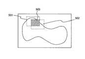
Further, although the objective lens magnification is set to a high magnification for a plurality of shooting positions / areas and shooting is started in the designated area according to the field size of the objective lens, the area once shot is not shot in multiple. This will be described with reference to FIG.
図7は、本実施形態における複数箇所のマーキングから複数の撮影領域の撮影をする際の例を示す。図7には第1の撮影領域501と第2の撮影領域502があり、更に2つの領域が重複する領域503があるとする。第1の撮影領域501で領域503を撮影した場合に、第2の撮影領域502の撮影時にはこの重複する領域503は撮影しないものとする。 FIG. 7 shows an example when photographing a plurality of photographing regions from a plurality of markings in the present embodiment. In FIG. 7, it is assumed that there are a
なお、第1の実施形態においてもこのような重複する撮影領域は、本実施形態と同様に処理することができる。
以上より、本実施形態では、親画像を遡る必要がないので、処理が簡略化されて、処理の高速化を図ることができる。Note that, in the first embodiment, such overlapping imaging regions can be processed in the same manner as in this embodiment.
As described above, in this embodiment, since it is not necessary to go back to the parent image, the processing is simplified and the processing speed can be increased.
<第3の実施形態>
図8は、本実施形態における顕微鏡画像撮影装置をネットワーク上に拡張した例を示す。ネットワーク810を介して、顕微鏡画像撮影装置801、コンピュータ811,812,813,814とを接続し、コンピュータ811,812,813,814のいずれからも顕微鏡画像撮影装置を制御可能にする。<Third Embodiment>
FIG. 8 shows an example in which the microscope image capturing apparatus according to this embodiment is extended on a network. The microscope
ネットワーク810は、ローカルエリアネットワーク(LAN)や公衆網を使って接続するワイドエリアネットワーク(WAN)であっても良い。このような接続により、一度顕微鏡画像撮影装置801で撮影した必要最小限の領域内の高精細画像を、複数のユーザがコンピュータ811,812,813,814から観察することができる。 The
また、コンピュータ120,811,812,813,814の観察画面やマウスポインタを連携することで指導医からの観察手法の教授をしたりすることができたりする。また、一度、顕微鏡画像撮影装置801で撮影した画像を観察するだけでなく、ネットワーク810上のコンピュータ120,811,812,813,814のいずれからも必要最小限の領域内の高精細画像を撮影することができる。 In addition, the observation method of the
また、病理医間のカンファレンスで用いる場合には、予め注目している領域を依頼側となる病理医が決定しておき、その領域を高精細画像で取り込んでおき、この画像情報をネットワーク上に接続している他の病理医に非同期に閲覧してもらうことも可能である。
<第4の実施形態>
第1の実施形態では、指導医が診断した観察ログから重要な箇所(マーキングされた箇所)を自動認識し、必要な領域のみ高精細な画像の作成をしており、2次元の画像が1枚構築されることになる。本実施形態では、重要な領域を3次元画像構築できるように複数のフォーカス位置で撮影をして高精細画像を作成することを提案する。In addition, when used in a conference between pathologists, a pathologist on the request side determines an area of interest in advance, captures the area as a high-definition image, and stores this image information on the network. It is also possible to have other connected pathologists browse asynchronously.
<Fourth Embodiment>
In the first embodiment, an important part (marked part) is automatically recognized from an observation log diagnosed by a supervising doctor, and a high-definition image is created only in a necessary region. Will be built. In the present embodiment, it is proposed that a high-definition image is created by shooting at a plurality of focus positions so that a three-dimensional image can be constructed in an important region.
図9は、本実施形態におけるマーキングした重要な位置を含む領域内901を異なるZ位置で撮影したものを示す。指導医が診断した観察ログから重要な箇所901を認識し、取り込む位置・領域を決定すると共に複数の異なるZ位置を決定する。複数の異なるZ位置は、対物レンズにより異なる焦点深度情報を元にZ微動量(ΔZ)を決定しても良い。 FIG. 9 shows an image of an
図10は、本実施形態における画像取り込み手順のフローを示す図である。同図は、図2の変形であって、S204の処理の後、電動ステージまたは対物レンズをΔZ移動させて(S205)、再びS204の処理を行う。このようにS204、S205を所定回数(n(n>0)回)行う(S206)。これにより、ΔZのみ異なる同一領域の高精細画像がn枚作成される。これにより、当該領域に関して3次元画像の構築が実現できる。 FIG. 10 is a diagram showing a flow of an image capturing procedure in the present embodiment. This figure is a modification of FIG. 2, and after the process of S204, the motorized stage or the objective lens is moved by ΔZ (S205), and the process of S204 is performed again. Thus, S204 and S205 are performed a predetermined number of times (n (n> 0) times) (S206). As a result, n high-definition images of the same region that differ only by ΔZ are created. Thereby, construction of a three-dimensional image can be realized for the region.
以上より、適切なZ微動量により必要最小限の記録容量することができると共に、ステージの面精度が無くても、あるいは標本自体に平坦性がなくても、撮影時にフォーカスコントロールすることなく撮影できる。また、Z軸方向に同一領域の画像が複数作成され、これより3次元画像が構築されているので、観察者は、一度撮影した異なるZ位置の領域画像より顕微鏡を操作してフォーカスを微調整するように、この操作と同期した画像を表示させることが可能になる。また標本全体の領域について異なるZ位置の撮影をすることがないので、必要最小限の記録容量で済むことになる。 As described above, the minimum necessary recording capacity can be achieved by an appropriate amount of Z fine movement, and even if there is no surface precision of the stage or the specimen itself is not flat, it is possible to take an image without focus control during imaging. . In addition, multiple images of the same region are created in the Z-axis direction, and a three-dimensional image is constructed from this, so the observer can fine-tune the focus by operating the microscope from the region images of different Z positions that were taken once. As a result, an image synchronized with this operation can be displayed. In addition, since there is no need to photograph different Z positions for the entire region of the specimen, the minimum necessary recording capacity is required.
なお、本実施形態は、第1の実施形態だけでなく、第2の実施形態に用いても良い。 Note that this embodiment may be used not only in the first embodiment but also in the second embodiment.
100 顕微鏡画像撮影装置
101 ディスプレイドライバ
102 画像キャプチャ
103 モニタ
105 顕微鏡コントローラ
106 ステージコントローラ
107 顕微鏡
108 電動ステージ
109 顕微鏡像用のTVカメラ
110 CPUバス
111,112 通信I/F
113 大容量記録媒体
114 制御ドライバ
115 キーボード/マウス
116 メモリ
117 CPU
120 コンピュータ
801 顕微鏡画像撮影装置
810 ネットワーク
811,812,813,814 コンピュータ
DESCRIPTION OF
113
120
Claims (8)
Translated fromJapanese低倍率で取り込んだ前記画像を親画像とし、該親画像中の一部の領域に対応する前記標本の部位を倍率を上げて取り込んだ画像を子画像として、順次これらの取り込まれた画像間の親子関係情報を記憶する記憶手段と、
前記子画像のうち所定の子画像に対応する所定の親画像である対象親画像を前記親子関係情報に基づいて決定する対象親画像決定手段と、
前記対象親画像の座標情報と所定の倍率情報とに基づいて、該対象親画像の撮影領域を分割した小区画を算出する小区画算出手段と、
前記小区画算出手段により算出された小区画に対応する前記標本の部位を前記所定の倍率情報の示す倍率により順次撮影する小区画撮影手段と、
前記小区画撮影手段により撮影した複数の前記小区画の画像を連続した一枚の画像に合成する小区画合成手段と、
を備えることを特徴とする顕微鏡画像撮影システム。In a microscope image capturing system that can capture a desired position of a specimen to be observed at a desired magnification and capture it as an image,
The image captured at a low magnification is used as a parent image, and the portion of the sample corresponding to a part of the region in the parent image is increased as a child image. Storage means for storing parent-child relationship information;
Target parent image determination means for determining a target parent image that is a predetermined parent image corresponding to a predetermined child image among the child images based on the parent-child relationship information;
Sub-partition calculation means for calculating a sub-partition obtained by dividing the photographing region of the target parent image based on the coordinate information of the target parent image and predetermined magnification information;
Sub-section imaging means for sequentially imaging the portion of the specimen corresponding to the sub-section calculated by the sub-section calculation means at a magnification indicated by the predetermined magnification information;
Sub-compartment synthesizing means for compositing a plurality of images of the sub-sections captured by the sub-section imaging means into a single continuous image;
A microscope image photographing system comprising:
低倍率で取り込んだ前記画像を親画像とし、該親画像中の一部の領域に対応する前記標本の部位を倍率を上げて取り込んだ画像を子画像として、順次これらの取り込まれた画像間の親子関係情報を記憶する記憶手段と、
前記子画像のうち所定の子画像の注目領域の座標を読み出す読み出し手段と、
前記座標を含む所定領域を表す情報と所定の倍率情報とに基づいて、該所定領域を分割した小区画を算出する小区画算出手段と、
前記小区画算出手段により算出された小区画に対応する前記標本の部位を前記所定の倍率情報の示す倍率により順次撮影する小区画撮影手段と、
前記小区画撮影手段により撮影した複数の前記小区画の画像を連続した一枚の画像に合成する小区画合成手段と、
を備えることを特徴とする顕微鏡画像撮影システム。In a microscope image capturing system that can capture a desired position of a specimen to be observed at a desired magnification and capture it as an image,
The image captured at a low magnification is used as a parent image, and the portion of the sample corresponding to a part of the region in the parent image is increased as a child image. Storage means for storing parent-child relationship information;
Reading means for reading out the coordinates of the attention area of a predetermined child image among the child images;
Subsection calculation means for calculating a subsection obtained by dividing the predetermined area based on information representing the predetermined area including the coordinates and predetermined magnification information;
Sub-section imaging means for sequentially imaging the portion of the specimen corresponding to the sub-section calculated by the sub-section calculation means at a magnification indicated by the predetermined magnification information;
Sub-compartment synthesizing means for compositing a plurality of images of the sub-sections captured by the sub-section imaging means into a single continuous image;
A microscope image photographing system comprising:
前記小区画合成手段により合成した画像である合成画像を前記対象親画像に関連付ける合成画像関連付け手段
を備えることを特徴とする請求項1、又は2に記載の顕微鏡画像撮影システム。The microscope image capturing system further includes:
The microscope image photographing system according to claim 1, further comprising: a composite image associating unit that associates a composite image that is an image combined by the small section combining unit with the target parent image.
前記合成画像の表示倍率を変更する表示倍率変更手段
を備えることを特徴とする請求項3に記載の顕微鏡画像撮影システム。The microscope image capturing system further includes:
The microscope image photographing system according to claim 3, further comprising display magnification changing means for changing a display magnification of the composite image.
前記標本の撮影に使用される対物レンズと前記標本との間の光軸方向の相対位置を変化させる位置変化手段
を備えることを特徴とする請求項1、又は2に記載の顕微鏡画像撮影システム。The microscope image capturing system further includes:
The microscope image photographing system according to claim 1, further comprising: a position changing unit that changes a relative position in an optical axis direction between the objective lens used for photographing the specimen and the specimen.
1つ又は複数のクライアント装置を備え、
前記クライアント装置から当該前記顕微鏡画像撮影システムを制御すること
を特徴とする請求項1〜5のいずれか1項に記載の顕微鏡画像撮影システム。The microscope image capturing system further includes:
Comprising one or more client devices;
The microscope image photographing system according to any one of claims 1 to 5, wherein the microscope image photographing system is controlled from the client device.
低倍率で取り込んだ前記画像を親画像とし、該親画像中の一部の領域に対応する前記標本の部位を倍率を上げて取り込んだ画像を子画像として、順次これらの取り込まれた画像間の親子関係情報を記憶し、
前記子画像のうち所定の子画像に対応する所定の親画像である対象親画像を前記親子関係情報に基づいて決定し、
前記対象親画像の座標情報と所定の倍率情報とに基づいて、該対象親画像の撮影領域を分割した小区画を算出し、
前記小区画算出手段により算出された小区画に対応する前記標本の部位を前記所定の倍率情報の示す倍率により順次撮影し、
前記小区画撮影手段により撮影した複数の前記小区画の画像を連続した一枚の画像に合成する
ことを特徴とする顕微鏡画像撮影方法。In a microscopic image capturing method for capturing a desired position of a specimen to be observed at a desired magnification and capturing it as an image,
The image captured at a low magnification is used as a parent image, and the portion of the sample corresponding to a part of the region in the parent image is increased as a child image. Memorize parent-child relationship information,
A target parent image that is a predetermined parent image corresponding to a predetermined child image among the child images is determined based on the parent-child relationship information,
Based on the coordinate information of the target parent image and predetermined magnification information, calculate a small section obtained by dividing the shooting region of the target parent image,
Sequentially photographing the part of the specimen corresponding to the small section calculated by the small section calculating means at a magnification indicated by the predetermined magnification information;
A microscopic image photographing method comprising combining a plurality of images of the small sections photographed by the small section photographing means into a continuous image.
低倍率で取り込んだ前記画像を親画像とし、該親画像中の一部の領域に対応する前記標本の部位を倍率を上げて取り込んだ画像を子画像として、順次これらの取り込まれた画像間の親子関係情報を記憶する記憶処理と、
前記子画像のうち所定の子画像に対応する所定の親画像である対象親画像を前記親子関係情報に基づいて決定する対象親画像決定処理と、
前記対象親画像の座標情報と所定の倍率情報とに基づいて、該対象親画像の撮影領域を分割した小区画を算出する小区画算出処理と、
前記小区画算出処理により算出された小区画に対応する前記標本の部位を前記所定の倍率情報の示す倍率により順次撮影する小区画撮影処理と、
前記小区画撮影処理により撮影した複数の前記小区画の画像を連続した一枚の画像に合成する小区画合成処理と、
を、コンピュータに実行させるための顕微鏡画像撮影プログラム。
In a microscopic image photographing program for causing a computer to capture a desired position of a specimen to be observed at a desired magnification and capture it as an image,
The image captured at a low magnification is used as a parent image, and the portion of the sample corresponding to a part of the region in the parent image is increased as a child image. A storage process for storing parent-child relationship information;
A target parent image determination process for determining a target parent image that is a predetermined parent image corresponding to a predetermined child image among the child images based on the parent-child relationship information;
A small section calculation process for calculating a small section obtained by dividing the imaging region of the target parent image based on the coordinate information of the target parent image and predetermined magnification information;
A small section photographing process for sequentially photographing the portion of the sample corresponding to the small section calculated by the small section calculation process at a magnification indicated by the predetermined magnification information;
Sub-compartment synthesis processing for compositing a plurality of images of the sub-sections captured by the sub-section imaging processing into a single continuous image;
Microscope image photographing program for causing a computer to execute.
Priority Applications (1)
| Application Number | Priority Date | Filing Date | Title |
|---|---|---|---|
| JP2004083240AJP2005266718A (en) | 2004-03-22 | 2004-03-22 | Microscopic image photographing system |
Applications Claiming Priority (1)
| Application Number | Priority Date | Filing Date | Title |
|---|---|---|---|
| JP2004083240AJP2005266718A (en) | 2004-03-22 | 2004-03-22 | Microscopic image photographing system |
Publications (1)
| Publication Number | Publication Date |
|---|---|
| JP2005266718Atrue JP2005266718A (en) | 2005-09-29 |
Family
ID=35091279
Family Applications (1)
| Application Number | Title | Priority Date | Filing Date |
|---|---|---|---|
| JP2004083240APendingJP2005266718A (en) | 2004-03-22 | 2004-03-22 | Microscopic image photographing system |
Country Status (1)
| Country | Link |
|---|---|
| JP (1) | JP2005266718A (en) |
Cited By (9)
| Publication number | Priority date | Publication date | Assignee | Title |
|---|---|---|---|---|
| JP2007316259A (en)* | 2006-05-24 | 2007-12-06 | Olympus Corp | Microscope system, method for recording microscopic image, and program |
| JP2010217761A (en)* | 2009-03-18 | 2010-09-30 | Olympus Corp | Image acquiring device, image acquisition method, and program |
| JP2011112523A (en)* | 2009-11-27 | 2011-06-09 | Sony Corp | Information processor, information processing method, and program of the same |
| US8363099B2 (en) | 2008-12-08 | 2013-01-29 | Olympus Corporation | Microscope system and method of operation thereof |
| JP2014186332A (en)* | 2014-04-28 | 2014-10-02 | Olympus Corp | Fluorescence observation apparatus |
| JP2014224929A (en)* | 2013-05-16 | 2014-12-04 | オリンパス株式会社 | Microscope system |
| CN104251811A (en)* | 2013-06-28 | 2014-12-31 | 西门子医疗保健诊断公司 | Digital microscope and image identification method |
| US9230058B2 (en) | 2011-01-25 | 2016-01-05 | Sony Corporation | Image processing device, image processing method and program |
| CN113723152A (en)* | 2020-05-26 | 2021-11-30 | 阿里巴巴集团控股有限公司 | Image processing method and device and electronic equipment |
Citations (7)
| Publication number | Priority date | Publication date | Assignee | Title |
|---|---|---|---|---|
| JPH0651209A (en)* | 1992-07-29 | 1994-02-25 | Olympus Optical Co Ltd | Microscopic still image observing system |
| JPH06281866A (en)* | 1993-03-30 | 1994-10-07 | Olympus Optical Co Ltd | Microscope image observing system |
| JPH09281405A (en)* | 1996-04-17 | 1997-10-31 | Olympus Optical Co Ltd | Microscopic system |
| JPH11183802A (en)* | 1997-12-24 | 1999-07-09 | Olympus Optical Co Ltd | Microscope system |
| JPH11275572A (en)* | 1998-03-25 | 1999-10-08 | Nikon Corp | Microscope image display system and microscope image transmission and display system |
| JP2001024923A (en)* | 1999-07-08 | 2001-01-26 | Fuji Photo Film Co Ltd | Device and method for photographing and recording medium |
| JP2004297657A (en)* | 2003-03-28 | 2004-10-21 | Sanyo Electric Co Ltd | Image processing apparatus |
- 2004
- 2004-03-22JPJP2004083240Apatent/JP2005266718A/enactivePending
Patent Citations (7)
| Publication number | Priority date | Publication date | Assignee | Title |
|---|---|---|---|---|
| JPH0651209A (en)* | 1992-07-29 | 1994-02-25 | Olympus Optical Co Ltd | Microscopic still image observing system |
| JPH06281866A (en)* | 1993-03-30 | 1994-10-07 | Olympus Optical Co Ltd | Microscope image observing system |
| JPH09281405A (en)* | 1996-04-17 | 1997-10-31 | Olympus Optical Co Ltd | Microscopic system |
| JPH11183802A (en)* | 1997-12-24 | 1999-07-09 | Olympus Optical Co Ltd | Microscope system |
| JPH11275572A (en)* | 1998-03-25 | 1999-10-08 | Nikon Corp | Microscope image display system and microscope image transmission and display system |
| JP2001024923A (en)* | 1999-07-08 | 2001-01-26 | Fuji Photo Film Co Ltd | Device and method for photographing and recording medium |
| JP2004297657A (en)* | 2003-03-28 | 2004-10-21 | Sanyo Electric Co Ltd | Image processing apparatus |
Cited By (15)
| Publication number | Priority date | Publication date | Assignee | Title |
|---|---|---|---|---|
| JP2007316259A (en)* | 2006-05-24 | 2007-12-06 | Olympus Corp | Microscope system, method for recording microscopic image, and program |
| US8363099B2 (en) | 2008-12-08 | 2013-01-29 | Olympus Corporation | Microscope system and method of operation thereof |
| JP2010217761A (en)* | 2009-03-18 | 2010-09-30 | Olympus Corp | Image acquiring device, image acquisition method, and program |
| US9615028B2 (en) | 2009-11-27 | 2017-04-04 | Sony Corporation | Method of displaying a pathological microscopic image, an information processing apparatus, a non-transitory computer-readable medium, and an information processing system |
| JP2011112523A (en)* | 2009-11-27 | 2011-06-09 | Sony Corp | Information processor, information processing method, and program of the same |
| US8761468B2 (en) | 2009-11-27 | 2014-06-24 | Sony Corporation | Information processing apparatus, information processing method, and program |
| US11342063B2 (en) | 2009-11-27 | 2022-05-24 | Sony Corporation | Information processing apparatus, information processing method, and program |
| US10506167B2 (en) | 2009-11-27 | 2019-12-10 | Sony Corporation | Information processing apparatus, information processing method, and program |
| US10091426B2 (en) | 2009-11-27 | 2018-10-02 | Sony Corporation | Information processing apparatus, information processing method, and program |
| US9177375B2 (en) | 2009-11-27 | 2015-11-03 | Sony Corporation | Information processing apparatus, information processing method, and program |
| US9230058B2 (en) | 2011-01-25 | 2016-01-05 | Sony Corporation | Image processing device, image processing method and program |
| JP2014224929A (en)* | 2013-05-16 | 2014-12-04 | オリンパス株式会社 | Microscope system |
| CN104251811A (en)* | 2013-06-28 | 2014-12-31 | 西门子医疗保健诊断公司 | Digital microscope and image identification method |
| JP2014186332A (en)* | 2014-04-28 | 2014-10-02 | Olympus Corp | Fluorescence observation apparatus |
| CN113723152A (en)* | 2020-05-26 | 2021-11-30 | 阿里巴巴集团控股有限公司 | Image processing method and device and electronic equipment |
Similar Documents
| Publication | Publication Date | Title |
|---|---|---|
| JP4878913B2 (en) | Microscope system, microscope image synthesis method, and program | |
| JP4970869B2 (en) | Observation apparatus and observation method | |
| JP4667944B2 (en) | Image creation device | |
| US8000560B2 (en) | Virtual slide generation device, virtual slide generation method, virtual slide generation program product and virtual slide generation program transmission medium | |
| JP4937850B2 (en) | Microscope system, VS image generation method thereof, and program | |
| CA2436043C (en) | Focusable virtual microscopy apparatus and method | |
| JP4818592B2 (en) | Microscope system, microscope image display system, observation object image display method, and program | |
| JP2017194699A5 (en) | ||
| CN111788508B (en) | Digital microscope and method for changing the magnification of a digital microscope | |
| JP2017194700A5 (en) | ||
| US7756357B2 (en) | Microscope system for obtaining high and low magnification images | |
| JP2008052227A (en) | Observation apparatus | |
| JP5015381B2 (en) | Photomicroscope | |
| US20070285769A1 (en) | Microscope system and method for synthesizing microscopic images | |
| US7865007B2 (en) | Microscope system, observation method and observation program | |
| JP2014029380A (en) | Information processing device, information processing method, program, and image display device | |
| JP4637337B2 (en) | Microscope image observation system and control method thereof | |
| JP2005266718A (en) | Microscopic image photographing system | |
| EP1918751A1 (en) | Microscope system, observation method and observation program | |
| JP4878815B2 (en) | Microscope equipment | |
| JP4346888B2 (en) | Microscope equipment | |
| JP4046161B2 (en) | Sample image data processing method and sample inspection system | |
| KR100897674B1 (en) | Sample inspection system and sample inspection method | |
| JP4231915B2 (en) | Specimen inspection method and system | |
| JPH063600A (en) | Microscope system with macroscopic video function |
Legal Events
| Date | Code | Title | Description |
|---|---|---|---|
| A621 | Written request for application examination | Free format text:JAPANESE INTERMEDIATE CODE: A621 Effective date:20070322 | |
| A977 | Report on retrieval | Free format text:JAPANESE INTERMEDIATE CODE: A971007 Effective date:20100615 | |
| A131 | Notification of reasons for refusal | Free format text:JAPANESE INTERMEDIATE CODE: A131 Effective date:20100706 | |
| A02 | Decision of refusal | Free format text:JAPANESE INTERMEDIATE CODE: A02 Effective date:20101102 |