JP2005258526A - Desk holder and portable terminal device system - Google Patents
Desk holder and portable terminal device systemDownload PDFInfo
- Publication number
- JP2005258526A JP2005258526AJP2004065306AJP2004065306AJP2005258526AJP 2005258526 AJP2005258526 AJP 2005258526AJP 2004065306 AJP2004065306 AJP 2004065306AJP 2004065306 AJP2004065306 AJP 2004065306AJP 2005258526 AJP2005258526 AJP 2005258526A
- Authority
- JP
- Japan
- Prior art keywords
- connector
- terminal
- charging
- memory card
- memory
- Prior art date
- Legal status (The legal status is an assumption and is not a legal conclusion. Google has not performed a legal analysis and makes no representation as to the accuracy of the status listed.)
- Pending
Links
- 238000003780insertionMethods0.000claimsabstractdescription13
- 230000037431insertionEffects0.000claimsabstractdescription13
- 230000006870functionEffects0.000claimsabstractdescription8
- 238000012546transferMethods0.000claimsdescription50
- 238000000034methodMethods0.000claimsdescription10
- 238000006243chemical reactionMethods0.000claimsdescription4
- 230000006386memory functionEffects0.000abstractdescription4
- 238000010586diagramMethods0.000description5
- 238000012790confirmationMethods0.000description3
- 238000012544monitoring processMethods0.000description3
- 230000007704transitionEffects0.000description3
- 230000008569processEffects0.000description2
- 230000009467reductionEffects0.000description2
- 238000007792additionMethods0.000description1
- 230000006378damageEffects0.000description1
- 230000000694effectsEffects0.000description1
- 238000012986modificationMethods0.000description1
- 230000004048modificationEffects0.000description1
- 238000012545processingMethods0.000description1
Images


Classifications
- H—ELECTRICITY
- H02—GENERATION; CONVERSION OR DISTRIBUTION OF ELECTRIC POWER
- H02J—CIRCUIT ARRANGEMENTS OR SYSTEMS FOR SUPPLYING OR DISTRIBUTING ELECTRIC POWER; SYSTEMS FOR STORING ELECTRIC ENERGY
- H02J7/00—Circuit arrangements for charging or depolarising batteries or for supplying loads from batteries
- H02J7/0042—Circuit arrangements for charging or depolarising batteries or for supplying loads from batteries characterised by the mechanical construction
- H02J7/0044—Circuit arrangements for charging or depolarising batteries or for supplying loads from batteries characterised by the mechanical construction specially adapted for holding portable devices containing batteries
- H—ELECTRICITY
- H02—GENERATION; CONVERSION OR DISTRIBUTION OF ELECTRIC POWER
- H02J—CIRCUIT ARRANGEMENTS OR SYSTEMS FOR SUPPLYING OR DISTRIBUTING ELECTRIC POWER; SYSTEMS FOR STORING ELECTRIC ENERGY
- H02J7/00—Circuit arrangements for charging or depolarising batteries or for supplying loads from batteries
- H—ELECTRICITY
- H04—ELECTRIC COMMUNICATION TECHNIQUE
- H04M—TELEPHONIC COMMUNICATION
- H04M1/00—Substation equipment, e.g. for use by subscribers
- H04M1/72—Mobile telephones; Cordless telephones, i.e. devices for establishing wireless links to base stations without route selection
- H04M1/724—User interfaces specially adapted for cordless or mobile telephones
- H04M1/72403—User interfaces specially adapted for cordless or mobile telephones with means for local support of applications that increase the functionality
- H04M1/72409—User interfaces specially adapted for cordless or mobile telephones with means for local support of applications that increase the functionality by interfacing with external accessories
- H—ELECTRICITY
- H04—ELECTRIC COMMUNICATION TECHNIQUE
- H04M—TELEPHONIC COMMUNICATION
- H04M1/00—Substation equipment, e.g. for use by subscribers
- H04M1/26—Devices for calling a subscriber
- H04M1/27—Devices whereby a plurality of signals may be stored simultaneously
- H04M1/274—Devices whereby a plurality of signals may be stored simultaneously with provision for storing more than one subscriber number at a time, e.g. using toothed disc
- H04M1/2745—Devices whereby a plurality of signals may be stored simultaneously with provision for storing more than one subscriber number at a time, e.g. using toothed disc using static electronic memories, e.g. chips
- H04M1/2753—Devices whereby a plurality of signals may be stored simultaneously with provision for storing more than one subscriber number at a time, e.g. using toothed disc using static electronic memories, e.g. chips providing data content
- H04M1/2757—Devices whereby a plurality of signals may be stored simultaneously with provision for storing more than one subscriber number at a time, e.g. using toothed disc using static electronic memories, e.g. chips providing data content by data transmission, e.g. downloading
- H—ELECTRICITY
- H04—ELECTRIC COMMUNICATION TECHNIQUE
- H04M—TELEPHONIC COMMUNICATION
- H04M1/00—Substation equipment, e.g. for use by subscribers
- H04M1/72—Mobile telephones; Cordless telephones, i.e. devices for establishing wireless links to base stations without route selection
- H04M1/724—User interfaces specially adapted for cordless or mobile telephones
- H04M1/72403—User interfaces specially adapted for cordless or mobile telephones with means for local support of applications that increase the functionality
- H04M1/7243—User interfaces specially adapted for cordless or mobile telephones with means for local support of applications that increase the functionality with interactive means for internal management of messages
- H—ELECTRICITY
- H04—ELECTRIC COMMUNICATION TECHNIQUE
- H04M—TELEPHONIC COMMUNICATION
- H04M2250/00—Details of telephonic subscriber devices
- H04M2250/14—Details of telephonic subscriber devices including a card reading device
Landscapes
- Engineering & Computer Science (AREA)
- Power Engineering (AREA)
- Human Computer Interaction (AREA)
- Computer Networks & Wireless Communication (AREA)
- Signal Processing (AREA)
- Charge And Discharge Circuits For Batteries Or The Like (AREA)
- Telephone Set Structure (AREA)
- Telephone Function (AREA)
- Secondary Cells (AREA)
- Mobile Radio Communication Systems (AREA)
Abstract
Description
Translated fromJapanese本発明は携帯端末機器用の卓上ホルダに関し、特に携帯端末機器に内蔵された電池パックを充電する機能と外部メモリ機能とを有する卓上ホルダに関する。 The present invention relates to a desktop holder for a mobile terminal device, and more particularly to a desktop holder having a function of charging a battery pack built in the mobile terminal device and an external memory function.
携帯電話機に代表される携帯端末機器は、電池パックを電源として動作するため、定期的に充電する必要がある。そのため、電池パックを充電する機能を有する携帯端末機器用の卓上ホルダが、携帯端末機器とセットで販売され、また個別に販売されている。 A mobile terminal device typified by a mobile phone operates using a battery pack as a power source, and therefore needs to be charged regularly. For this reason, desktop holders for portable terminal devices having a function of charging a battery pack are sold as a set together with the portable terminal device, and are sold separately.
また携帯端末機器は、高付加価値化や高機能化が要求されており、それに伴ってメモリ容量の増加が必須の状況下にある。メモリ容量を増加させる場合、内蔵メモリの容量を増大させる方法と外部メモリを利用する方法とがあるが、小型軽量薄型化が望まれる携帯端末機器の場合、内蔵メモリの容量拡大には限度がある。このため、外部メモリとして本体から着脱可能なメモリカードを搭載することが主流になりつつある。メモリカードは、フラッシュメモリを使用したカード型の記憶装置であり、代表的なものに、MMC(マルチメディアカード)、SDメモリカード、メモリスティックなどがある。 In addition, mobile terminal devices are required to have high added value and high functionality, and accordingly, an increase in memory capacity is indispensable. To increase the memory capacity, there are a method of increasing the capacity of the built-in memory and a method of using an external memory. However, there is a limit to the capacity expansion of the built-in memory in the case of a portable terminal device that is desired to be small and light. . For this reason, it is becoming mainstream to mount a memory card that is removable from the main body as an external memory. The memory card is a card-type storage device using a flash memory, and representative examples include an MMC (multimedia card), an SD memory card, and a memory stick.
他方、特許文献1には、携帯電話機に内蔵された電池パックを充電する機能と外部メモリ機能とを有する充電器アダプタが提案されている。この充電器アダプタは、商用電源のコンセントに差し込む差込プラグと発光素子とを備えたアダプタ部と、携帯電話機の外部接続端子に接続されるコネクタと、前記アダプタ部と前記コネクタとを電気的に接続する接続手段とを有し、前記アダプタ部は、商用電源からの交流電圧を充電用直流電圧に変換して前記コネクタ及び接続手段を介して携帯電話機に供給し、電池パックを充電させるAC/DC変換器と、電池パックの充電が完了したかどうかを監視する充電監視手段と、外部記憶としての記憶手段と、充電監視手段により充電完了が検出されると、携帯電話機の内部メモリから少なくとも電話帳データを含む記憶データを転送させて前記記憶手段に記憶させると共に、前記発光素子によりデータ転送中を報知する制御手段とを有している。また、充電器アダプタに設けた切替スイッチによって、充電完了時に携帯電話機の内部メモリから前記記憶手段にデータを転送するかどうかを設定可能とする構成や、充電完了時に、携帯電話機の内部メモリから前記記憶手段へのデータ転送、その逆の前記記憶手段から内部メモリへのデータ転送の何れを行うか或いはその何れも行わないかを、設定可能とする構成も記載されている。
特許文献1に記載される充電器アダプタによれば、携帯電話機の電池パックの充電完了時に携帯電話機の内部メモリに記憶されている電話帳データを含む記憶データを充電器アダプタに内蔵される記憶手段に自動的に保存したり、その逆に充電器アダプタに保存しておいた記憶データを携帯電話機の内部メモリに自動的に転送することができる。 According to the charger adapter described in
しかしながら、充電器アダプタに内蔵される記憶手段は着脱可能なものでなく、然も携帯電話機以外とはデータの転送が行えないため、外部メモリに保存したデータをパーソナルコンピュータや他の種類の携帯端末機器で利用することができず、データの共有性に難がある。また、キー操作によって、例えば、内部メモリに記憶されたデータのうち利用者が選択したデータだけを外部メモリに保存すると言ったアクセス制御が行えない。他方、メモリカード装着対応の携帯端末機器によれば、このような課題は解消されるが、そのためには携帯端末機器にメモリカードを搭載するだけのスペースが必要であり、小型軽量化に反するし、メモリカードの消費電力だけ携帯端末機器の消費電力が増大してしまう。 However, the storage means built in the charger adapter is not detachable, and data cannot be transferred to devices other than mobile phones, so data stored in an external memory can be stored in a personal computer or other types of mobile terminals. It cannot be used with devices, and data sharing is difficult. Also, access control such as saving only data selected by the user from the data stored in the internal memory to the external memory by the key operation cannot be performed. On the other hand, according to the portable terminal device compatible with the memory card, such a problem is solved, but for that purpose, a space for mounting the memory card on the portable terminal device is necessary, which is contrary to the reduction in size and weight. Therefore, the power consumption of the portable terminal device increases by the power consumption of the memory card.
本発明はこのような事情に鑑みて提案されたものであり、その目的は、電池パックを充電する機能と外部メモリ機能とを有し、外部メモリとして着脱自在なメモリカードを使用でき、しかも携帯端末機器のキー操作によってメモリカードに対するアクセスを制御することができる卓上ホルダ及び携帯端末機器システムを提供することにある。 The present invention has been proposed in view of such circumstances, and the object thereof is to have a function of charging a battery pack and an external memory function, and a removable memory card can be used as an external memory, and it is portable. An object of the present invention is to provide a desktop holder and a portable terminal device system that can control access to a memory card by key operation of the terminal device.
本発明の第1の卓上ホルダは、メモリカード用スロットに装填されたメモリカードと携帯端末機器の外部接続端子とを電気的に接続する複数のコネクタを備え、ACアダプタから供給される充電用直流電圧を前記携帯端末機器に供給して電池パックの充電を可能にするとともに、前記携帯端末機器のキー操作によって前記携帯端末機器から前記メモリカードに対する読み書きを可能にしたことを特徴とする。 A first desktop holder according to the present invention includes a plurality of connectors that electrically connect a memory card loaded in a memory card slot and an external connection terminal of a mobile terminal device, and is a charging direct current supplied from an AC adapter. A voltage is supplied to the portable terminal device to enable charging of the battery pack, and reading / writing to the memory card from the portable terminal device is enabled by a key operation of the portable terminal device.
本発明の第2の卓上ホルダは、商用電源の交流電圧を充電用直流電圧に変換して出力するACアダプタの出力端子と接続される充電端子を備えた第1のコネクタと、前記第1のコネクタの前記充電端子から前記充電用直流電圧を入力して動作電圧に変換し出力するレギュレータと、前記レギュレータの出力が印可される電源端子および外部記憶媒体用端子を備えた第2のコネクタと、前記第1のコネクタの前記充電端子に接続される充電端子および前記第2のコネクタの前記外部記憶媒体用端子に接続される端子を備えた第3のコネクタとを筐体に内蔵し、前記第2のコネクタは前記筐体に設けられたメモリカード用スロットに装着され、前記第3のコネクタは前記筐体に設けられた携帯端末機器挿入口に装着されており、ACアダプタから供給される充電用直流電圧を前記携帯端末機器に供給して電池パックの充電を可能にするとともに、前記携帯端末機器のキー操作によって前記携帯端末機器から前記メモリカードに対する読み書きを可能にしたことを特徴とする。 The second desktop holder according to the present invention includes a first connector having a charging terminal connected to an output terminal of an AC adapter that converts an AC voltage of a commercial power source into a DC voltage for charging and outputs the same, and the first connector A regulator that inputs the DC voltage for charging from the charging terminal of the connector, converts it into an operating voltage, and outputs it; a second connector having a power supply terminal to which the output of the regulator is applied; and a terminal for an external storage medium; A third connector having a charging terminal connected to the charging terminal of the first connector and a terminal connected to the external storage medium terminal of the second connector; The second connector is attached to a memory card slot provided in the casing, and the third connector is attached to a portable terminal device insertion slot provided in the casing. The battery pack can be charged by supplying a supplied DC voltage for charging to the portable terminal device, and reading / writing to the memory card from the portable terminal device can be performed by key operation of the portable terminal device. Features.
本発明の第1の携帯端末機器システムは、携帯端末機器と卓上ホルダとを含むシステムであって、前記卓上ホルダは、商用電源の交流電圧を充電用直流電圧に変換して出力するACアダプタの出力端子と接続される充電端子を備えた第1のコネクタと、前記第1のコネクタの前記充電端子から前記充電用直流電圧を入力して動作電圧に変換し出力するレギュレータと、前記レギュレータの出力が印可される電源端子および外部記憶媒体用端子を備えた第2のコネクタと、前記第1のコネクタの前記充電端子に接続される充電端子、外部インタフェース用端子および前記第2のコネクタの前記外部記憶媒体用端子に接続される外部記憶媒体用端子を備えた第3のコネクタとを筐体に内蔵し、前記第2のコネクタは前記筐体に設けられたメモリカード用スロットに装着され、前記第3のコネクタは前記筐体に設けられた携帯端末機器挿入口に装着されており、前記携帯端末機器は、前記第3のコネクタと電気的かつ物理的に接続される充電端子、外部インタフェース用端子および外部記憶媒体用端子を備えた第4のコネクタと、前記第4のコネクタの前記充電端子から前記充電用直流電圧を入力して電池パックを充電する充電回路と、内部メモリと、表示装置と、キー装置と、前記第4のコネクタの前記外部インタフェース用端子および外部記憶媒体用端子、前記内部メモリ、前記表示装置ならびに前記キー装置に接続され、前記キー装置からの利用者入力に従って前記メモリカードに対する読み書きを制御する制御手段とを備えることを特徴とする。 A first portable terminal device system according to the present invention is a system including a portable terminal device and a desktop holder, and the desktop holder converts an AC voltage of a commercial power source into a DC voltage for charging and outputs it. A first connector having a charging terminal connected to an output terminal; a regulator for inputting the DC voltage for charging from the charging terminal of the first connector to convert it into an operating voltage; and an output of the regulator A second connector having a power supply terminal and an external storage medium terminal applied thereto, a charging terminal connected to the charging terminal of the first connector, an external interface terminal, and the external of the second connector And a third connector having an external storage medium terminal connected to the storage medium terminal. The second connector is a memory card provided in the casing. The third connector is attached to a portable terminal device insertion slot provided in the housing, and the portable terminal device is electrically and physically connected to the third connector. And a charging circuit for charging the battery pack by inputting the DC voltage for charging from the charging terminal of the fourth connector, and a fourth connector having a charging terminal, an external interface terminal and an external storage medium terminal. An internal memory, a display device, a key device, the external interface terminal and the external storage medium terminal of the fourth connector, the internal memory, the display device, and the key device, and the key device Control means for controlling reading and writing with respect to the memory card in accordance with a user input from.
本発明の第2の携帯端末機器システムは、携帯端末機器と卓上ホルダとを含むシステムであって、前記卓上ホルダは、商用電源の交流電圧を充電用直流電圧に変換して出力するACアダプタの出力端子と接続される充電端子を備えた第1のコネクタと、前記第1のコネクタの前記充電端子から前記充電用直流電圧を入力して動作電圧に変換し出力するレギュレータと、前記レギュレータの出力が印可される電源端子および外部記憶媒体用端子を備えた第2のコネクタと、前記第1のコネクタの前記充電端子に接続される充電端子および前記第2のコネクタの前記外部記憶媒体用端子に接続される外部記憶媒体用端子を備えた第3のコネクタと、前記第2のコネクタの前記外部記憶媒体端子と前記第3の外部インタフェース端子とを接続するインタフェース変換機能を有する制御手段とを筐体に内蔵し、前記第2のコネクタは前記筐体に設けられたメモリカード用スロットに装着され、前記第3のコネクタは前記筐体に設けられた携帯端末機器挿入口に装着されており、前記携帯端末機器は、前記第3のコネクタと電気的かつ物理的に接続される充電端子および外部インタフェース用端子を備えた第4のコネクタと、前記第4のコネクタの前記充電端子から前記充電用直流電圧を入力して電池パックを充電する充電回路と、内部メモリと、表示装置と、キー装置と、前記第4のコネクタの前記外部インタフェース用端子、前記内部メモリ、前記表示装置および前記キー装置に接続され、前記キー装置からの利用者入力に従って前記メモリカードに対する読み書きを制御する制御手段とを備えることを特徴とする。 A second portable terminal device system according to the present invention is a system including a portable terminal device and a desktop holder, and the desktop holder converts an AC voltage of a commercial power source into a DC voltage for charging and outputs it. A first connector having a charging terminal connected to an output terminal; a regulator for inputting the DC voltage for charging from the charging terminal of the first connector to convert it into an operating voltage; and an output of the regulator A second connector having a power supply terminal and an external storage medium terminal to be applied; a charging terminal connected to the charging terminal of the first connector; and an external storage medium terminal of the second connector The third connector having a terminal for external storage medium to be connected, and the external connector for connecting the external storage medium terminal of the second connector and the third external interface terminal. Control means having a interface conversion function is incorporated in the housing, the second connector is mounted in a memory card slot provided in the housing, and the third connector is a portable device provided in the housing. The portable terminal device is attached to a terminal device insertion slot, and the portable terminal device includes a charging connector electrically and physically connected to the third connector, and a fourth connector having an external interface terminal, and the fourth connector. A charging circuit for charging the battery pack by inputting the charging DC voltage from the charging terminal of the connector, an internal memory, a display device, a key device, the external interface terminal of the fourth connector, Control means connected to the internal memory, the display device and the key device, and controls reading and writing to the memory card according to a user input from the key device; Characterized in that it comprises.
本発明の第3の携帯端末機器システムは、第2の携帯端末機器システムにおいて、前記卓上ホルダの前記制御手段は、携帯側アクセス制御部と、カード側アクセス制御部と、バッファメモリとを有し、前記携帯側アクセス制御部は前記第3のコネクタの外部インタフェース用端子を通じて前記携帯端末機器の前記制御手段との間で、外部インタフェースに応じた手順でデータおよび制御信号の授受を行い、前記メモリカードのライト時は前記携帯端末機器の前記制御手段から受信した前記内部メモリのデータを前記バッファメモリに蓄積し、前記メモリカードのリード時は前記バッファメモリに蓄積された前記メモリカードのデータを前記携帯端末機器の前記制御手段へ転送するものであり、前記カード側アクセス制御部は前記第2のコネクタの前記外部記憶媒体用端子を通じて前記メモリカードとの間で、外部記憶媒体インタフェースに応じた手順でデータおよび制御信号の授受を行い、前記メモリカードのライト時は前記バッファメモリに蓄積された前記内部メモリのデータを前記メモリカードに書き込み、前記メモリカードのリード時は前記メモリカードから読み出したデータを前記バッファメモリに蓄積するものであることを特徴とする。 According to a third portable terminal device system of the present invention, in the second portable terminal device system, the control means of the desktop holder includes a portable side access control unit, a card side access control unit, and a buffer memory. The portable side access control unit exchanges data and control signals with the control means of the portable terminal device through the external interface terminal of the third connector according to the procedure according to the external interface, and the memory When the card is written, the data in the internal memory received from the control means of the portable terminal device is stored in the buffer memory. When the memory card is read, the data in the memory card stored in the buffer memory is stored in the buffer memory. The card side access control unit transfers the second connection to the control means of the portable terminal device. Data and control signals are exchanged with the memory card through the external storage medium terminal in accordance with the procedure according to the external storage medium interface, and the internal data stored in the buffer memory is written when the memory card is written. Data in the memory is written into the memory card, and when the memory card is read, the data read from the memory card is stored in the buffer memory.
本発明の第4の携帯端末機器システムは、第1、第2または第3の携帯端末機器システムにおいて、前記携帯端末機器の前記制御手段は、前記内部メモリおよび前記メモリカード用スロットに装填されたメモリカードの一方を転送元メモリ、他方を転送先メモリとし、転送元メモリのフォルダ一覧を前記表示装置に表示して前記キー装置のキー操作によって利用者に転送元フォルダを選択させ、転送先メモリのフォルダ一覧を前記表示装置に表示して前記キー装置のキー操作によって利用者に転送先フォルダを選択させ、前記選択された転送元フォルダに記憶されたデータを読み出して前記選択された転送先フォルダに書き込むものであることを特徴とする。 According to a fourth portable terminal device system of the present invention, in the first, second or third portable terminal device system, the control means of the portable terminal device is loaded in the internal memory and the memory card slot. One of the memory cards is a transfer source memory, the other is a transfer destination memory, a folder list of the transfer source memory is displayed on the display device, and a user selects a transfer source folder by a key operation of the key device. The folder list is displayed on the display device, and a user selects a transfer destination folder by a key operation of the key device, and data stored in the selected transfer source folder is read to read the selected transfer destination folder. It is characterized by being written in.
本発明によれば、携帯端末機器の電池パックを充電するための卓上ホルダのスロットに装填されたメモリカードを携帯端末機器の外部メモリとして使用することができ、しかも携帯端末機器のキー操作によってメモリカードに対するアクセスを制御できる。 According to the present invention, the memory card loaded in the slot of the desktop holder for charging the battery pack of the mobile terminal device can be used as the external memory of the mobile terminal device, and the memory is operated by the key operation of the mobile terminal device. You can control access to the card.
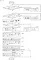
図1および図2を参照すると、本発明の第1の実施の形態にかかる携帯端末機器1用の卓上ホルダ2は、商用電源の交流電圧を5V程度の充電用直流電圧に変換して出力するACアダプタ3の出力端子301と接続される充電端子211を備えた第1のコネクタ21と、第1のコネクタ21の充電端子211からケーブル101を通じて充電用直流電圧を入力して3V程度の動作電圧に変換し、ケーブル102を通じて出力するレギュレータ22と、レギュレータ22の出力がケーブル102を通じて印可される電源端子231および外部記憶媒体用端子232を備えた第2のコネクタ23と、第1のコネクタ21の充電端子211にケーブル101を通じて接続される充電端子241、外部インタフェース用端子242および第2のコネクタ23の外部記憶媒体用端子232にケーブル103を通じて接続される外部記憶媒体用端子243を備えた第3のコネクタ24とを、筐体20に内蔵している。 Referring to FIGS. 1 and 2, the desktop holder 2 for the
筐体20は、その上面に携帯端末機器1用の挿入口25を有し、その側面にメモリカード4用のスロット26を有しており、第2のコネクタ23はメモリカード用スロット26の奥に取り付けられ、第3のコネクタ24は挿入口25の底面に取り付けられている。なお、筐体20の上部は斜めにカットされており、携帯端末機器1の表側を正面にして挿入口25に挿入した場合に、そのキー部11およびLCD12が完全に露出するようになっている。 The
他方、携帯端末機器1は、卓上ホルダ2の挿入口25に挿入した状態で第3のコネクタ24と電気的かつ物理的に接続される充電端子131、外部インタフェース用端子132および外部記憶媒体用端子133を備えた第4のコネクタ13と、電池パック14と、第4のコネクタ13の充電端子131から充電用直流電圧を入力して電池パック14を充電する充電回路15と、内部メモリ16と、LCD12と、各種のキーを有するキー部11と、第4のコネクタ13の外部インタフェース用端子132および外部記憶媒体用端子133、内部メモリ16、LCD12ならびにキー部11に接続された制御部17とを筐体10に内蔵している。制御部17は、MPUを含んで構成され、携帯端末機器1全体の制御を司る。特に本発明に関しては、キー部11からの利用者入力に従ってメモリカード4に対する読み書きを制御する機能を有している。 On the other hand, the
メモリカード4としてMMC(マルチメディアカード)を使用する場合、第2、第3および第4のコネクタ23、24および13の外部記憶媒体用端子232、243および133は、MMC用の端子群で構成される。メモリカード4として、SDメモリカードやメモリスティックなどの他の種類のものが使用される場合も同様に、使用する種類のメモリカードに適合する10芯程度の端子群で構成される。携帯端末機器1の外部記憶媒体用端子133は、第4のコネクタ13が卓上ホルダ2の第3のコネクタ24に結合されると、第3のコネクタ24の外部記憶媒体端子243およびケーブル103を通じて第2のコネクタ23の外部記憶媒体端子232と電気的に接続される。このため、メモリカード4がメモリカード用スロット26に装填され、メモリカード4の図示しない外部接続端子が第2のコネクタ23の外部記憶媒体端子232に接続されると、最終的に携帯端末機器1の外部記憶媒体用端子133に接続されることになり、携帯端末機器1からメモリカード4を直接にアクセスできることになる。 When an MMC (multimedia card) is used as the
また、商用電源に接続したACアダプタ3の出力端子301を卓上ホルダ2の第1のコネクタ21に接続すると、充電用直流電圧がケーブル101を通じてレギュレータ22および第3のコネクタ24の充電端子241に印可される。このため、充電用直流電圧が第4のコネクタ13の充電端子131を通じて充電回路15に供給され、充電回路15による電池パック14の充電が可能になる。また、レギュレータ22で生成された動作電圧がケーブル102、第2のコネクタ23の電源端子231を通じてメモリカード4に供給され、メモリカード4が動作可能となる。 When the
次に、携帯端末機器1から卓上ホルダ2のスロット26に装填したメモリカード4をアクセスする際の動作を詳細に説明する。 Next, the operation when accessing the
利用者は携帯端末機器1の内部メモリ16に記憶されているデータをメモリカード4にコピーしたり、その逆にメモリカード4に記憶されているデータを内部メモリ16にコピーする場合、携帯端末機器1を卓上ホルダ2の挿入口25に挿入し、第4のコネクタ13と第3のコネクタ24とを結合させる。そして、キー部11からメモリカード4のアクセス開始の指示を入力する。この指示をキー部11から受けた制御部17は、図3に示す処理を開始する。 When a user copies data stored in the
まず制御部17は、商用電源に接続されたACアダプタ3が卓上ホルダ2に接続されているかどうかを判別する(S101)。前述したようにACアダプタ3が卓上ホルダ2に接続されると、充電用直流電圧が第1のコネクタ21、ケーブル101、第3のコネクタ24、第4のコネクタ13を通じて充電回路15に印可されるので、充電回路15から充電用直流電圧の印可の有無を示す信号を制御部17に通知することで、制御部17においてACアダプタ3が卓上ホルダ2に接続されているかどうかを判別することができる。若し、ACアダプタ3が接続されていない場合、ACアダプタ3を接続するように促進するメッセージをLCD12に表示する(S102)。 First, the
卓上ホルダ2にACアダプタ3が接続されていることを確認すると、続いて制御部17は、スロット26にメモリカード4が装填されているかどうかを判別する(S103)。前述したようにスロット26の第2のコネクタ23にメモリカード4の図示しない外部接続端子が接続されると、ケーブル102を通じてレギュレータ22から供給される動作電圧が充電端子231を介してメモリカード4に供給され、メモリカード4が動作可能になっているので、第4のコネクタ13、第3のコネクタ24、ケーブル103および第2のコネクタ23を通じてメモリカード4をアクセスすることで、制御部17においてスロット26にメモリカード4が装填されているかどうかを判別することができる。若し、メモリカード4が装填されていない場合、メモリカードを装填するように促進するメッセージをLCD12に表示する(S104)。なお、ACアダプタ3が接続されていない場合、およびメモリカード4が挿入されていない場合、メモリカード4に対するリードまたはライト時にエラーになるので、そのエラー時点で、ACアダプタ3を接続すること及びメモリカード4を挿入することを利用者に促すメッセージをLCD12に表示するようにしてもよい。 When it is confirmed that the
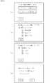
メモリカード4の装填を確認すると、次に制御部17は、メモリカード4に対するアクセス種別(ライト、リードの区別)の選択画面をLCD12に表示し、利用者の入力を待つ(S105)。図4(a)にアクセス種別の選択画面の一例を示す。「メモリカードに書き込む」、「メモリカードから読み出す」の何れか一方を、キー部11上のカーソルキーなどで選択し、実行ボタンを押下することで、アクセス種別が選択できるようになっている。 After confirming that the
制御部17は、アクセス種別の選択画面において、メモリカードに対するライトが選択された場合(S106でYES)、転送元メモリを内部メモリ16、転送先メモリをメモリカード4とする状態に遷移し(S107)、メモリカードに対するリードが選択された場合(S106でNO)、転送元メモリをメモリカード4、転送先メモリを内部メモリ16とする状態に遷移する(S108)。 When the write to the memory card is selected on the access type selection screen (YES in S106), the
次に制御部17は、転送元メモリをアクセスして、転送元メモリに存在するフォルダの一覧を求め、その一覧を含む転送元フォルダ選択画面をLCD12に表示し、利用者の入力を待つ(S109)。図4(b)に転送元フォルダ選択画面の一例を示す。この例は転送元メモリが内部メモリ16の場合のもので、「マイフォルダ」という名前のフォルダがあり、その下位に、「電話帳」、「メール」、「ピクチャ」という3つのフォルダがあることが示されており、その何れかのフォルダをキー部11上のカーソルキーなどで選択し、実行ボタンを押下することで、転送元フォルダが選択できるようになっている。制御部17は、転送元フォルダ選択画面でフォルダが選択されると、その選択されたフォルダを転送元フォルダとする状態に遷移する(S110)。 Next, the
次に制御部17は、転送先メモリをアクセスして、転送先メモリに存在するフォルダの一覧を求め、その一覧を含む転送先フォルダ選択画面をLCD12に表示し、利用者の入力を待つ(S111)。図4(c)に転送先フォルダ選択画面の一例を示す。この例は転送先メモリがメモリカーソルの場合のもので、「保存メール」という名前のフォルダがあり、その下位に、「会社」、「友人」という2つのフォルダがあることが示されており、その何れかのフォルダをキー部11上のカーソルキーなどで選択し、実行ボタンを押下することで、転送先フォルダが選択できるようになっている。制御部17は、転送先フォルダ選択画面でフォルダが選択されると、その選択されたフォルダを転送先フォルダとする状態に遷移する(S112)。 Next, the
次に制御部17は、選択された転送元フォルダと転送先フォルダを利用者に確認させる確認画面をLCD12に表示し、利用者の入力を待つ(S113)。図4(d)に確認画面の一例を示す。この例は、アクセス種別がメモリカードのライトで、転送元フォルダとして内部メモリ16の「メール」フォルダが選択され、転送先フォルダとしてメモリカード4の「友人」フォルダが選択された場合のものである。利用者は、YESボタン、NOボタンの何れかを押下することで、実行の可否を指示するようになっている。 Next, the
制御部17は、確認画面上でNOボタンが押下されると、図3の処理を終了する。他方、YESボタンが押下されると、転送元フォルダの内容を転送元メモリからリードし、転送先メモリの転送先フォルダにライトする(S114)。なお、制御部17は転送元メモリから転送先メモリへのデータ転送中、LCD12の画面にデータ転送中である旨のメッセージを表示し、データ転送が終了すると、その旨のメッセージを表示する。 When the NO button is pressed on the confirmation screen, the
このように本実施の形態によれば、以下のような効果が得られる。 Thus, according to the present embodiment, the following effects can be obtained.
卓上ホルダ2に設けたメモリカード用スロット26に装填されたメモリカード4に対して携帯端末機器1からアクセスできるため、携帯端末機器1のメモリカード用スロットが不要になり、携帯端末機器1のより一層の小型軽量化が可能になる。 Since the
携帯端末機器のキー部11のキー操作によってメモリカード4に対するアクセスを制御することができる。 Access to the
メモリカード4の電源を、携帯端末機器1からでなく、ACアダプタ3から供給するため、携帯端末機器1の消費電力の増加を防ぐことができる。また、電池パック14を充電しながらメモリカード4の読み書きを実施することができるため、メモリカード4のアクセス中に電池切れで電源が落ち、データ破壊を招くようなことがなくなる。 Since the power of the
図5および図6を参照すると、本発明の第2の実施の形態にかかる携帯端末機器1a用の卓上ホルダ2aは、図1の第1の実施の形態にかかる卓上ホルダ2と比較して、以下の点が相違する。
(1)第3のコネクタ24aは、充電端子241と外部インタフェース端子242とを有し、外部記憶媒体用端子は備えていない。
(2)レギュレータ22からケーブル102を通じて動作電圧を受けて動作する制御部27およびLED28が追加されている。
(3)第3のコネクタ24aの外部インタフェース端子242はケーブル103−1を通じて制御部27に接続され、第2のコネクタ23の外部記憶媒体用端子232はケーブル103−2を通じて制御部27に接続されている。5 and 6, the desktop holder 2a for the portable terminal device 1a according to the second embodiment of the present invention is compared with the desktop holder 2 according to the first embodiment of FIG. The following points are different.
(1) The
(2) A
(3) The
他方、携帯端末機器1aは、図1の第1の実施の形態にかかる携帯端末機器1と比較して、以下の点が相違する。
(4)第4のコネクタ13aは、充電端子131と外部インタフェース端子132とを有し、外部記憶媒体用端子は備えていない。On the other hand, the portable terminal device 1a is different from the portable
(4) The
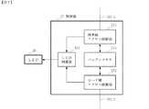
図7を参照すると、卓上ホルダ2aに設けられる制御部27は、携帯側アクセス制御部271と、カード側アクセス制御部272と、バッファメモリ273と、LED制御部274とで構成される。 Referring to FIG. 7, the
携帯側アクセス制御部271は、ケーブル103−1および第3のコネクタ24aの外部インタフェース用端子242、第4のコネクタ13aの外部インタフェース用端子132を通じて、携帯端末機器1aの制御部17との間で、外部インタフェースに応じた手順でデータおよび制御信号の授受を行い、メモリカード4のライト時は制御部17から受信した内部メモリ16のデータをバッファメモリ273に蓄積し、メモリカード4のリード時はバッファメモリ273に蓄積されたメモリカード4のデータを制御部17へ転送する。 The portable-side
カード側アクセス制御部272は、ケーブル103−2および第2のコネクタ23の外部記憶媒体用端子232を通じて、メモリカード4との間で、外部記憶媒体インタフェースに応じた手順でデータおよび制御信号の授受を行い、メモリカードのライト時はバッファメモリ273に蓄積された内部メモリ16のデータをメモリカード4に書き込み、メモリカードのリード時はメモリカード4から読み出したデータをバッファメモリ273に蓄積する。 The card side access control unit 272 exchanges data and control signals with the
これらの携帯側アクセス制御部271、カード側アクセス制御部272およびバッファメモリ273により、携帯端末機器1aの有する外部インタフェースとメモリカードの有する外部記憶媒体インタフェースとの間のインタフェース変換手段が構成される。 The mobile side
LED制御部274は、携帯側アクセス制御部271およびカード側アクセス制御部272が動作している期間中、LED28を点灯させる部分である。LED28は、ホルダの外から見えるように、卓上ホルダ1aの側面などに取り付けられており、利用者はLED28の点灯、消灯の状態により、メモリカード4のアクセス中、非アクセス中を認識できるようになっている。 The LED control unit 274 is a part that lights the
携帯端末機器1aから卓上ホルダ2aのスロット26に装填したメモリカード4をアクセスする際の動作は、上述したように卓上ホルダ2aの制御部27でインタフェース変換が実施される点を除いて、第1の実施の形態と同じである。 The operation when accessing the
本実施の形態では、携帯端末機器1aの第4のコネクタ13aに外部記憶媒体用端子を設ける必要がないので、第4のコネクタ13aの小型化が可能になる。 In the present embodiment, it is not necessary to provide an external storage medium terminal on the
以上本発明の実施の形態について説明したが、本発明は以上の実施の形態にのみ限定されず、その他各種の付加変更が可能である。例えば、前述した実施の形態では、卓上ホルダに1つのメモリカード用スロットと第2のコネクタを設けたが、種類の異なる複数のメモリカード用スロットと第2のコネクタを設けて、複数種類のメモリカードに対応できるように構成することも可能である。 Although the embodiment of the present invention has been described above, the present invention is not limited to the above embodiment, and various other additions and modifications can be made. For example, in the embodiment described above, the desktop holder is provided with one memory card slot and the second connector, but a plurality of different types of memory card slots and the second connector are provided to provide a plurality of types of memory. It is also possible to configure so as to be compatible with cards.
1、1a…携帯端末機器
10…筐体
101、102、103、103−1、103−2…ケーブル
11…キー部
12…LCD
13、13a…第4のコネクタ
131…充電端子
132…外部インタフェース用端子
133…外部記憶媒体用端子
14…電池パック
15…充電回路
16…内部メモリ
17…制御部
18…外部接続端子
2、2a…卓上ホルダ
20…筐体
21…第1のコネクタ
211…充電端子
22…レギュレータ
23…第2のコネクタ
231…電源端子
232…外部記憶媒体用端子
24、24a…第3のコネクタ
241…充電端子
242…外部インタフェース用端子
243…外部記憶媒体用端子
25…挿入口
26…スロット
27…制御部
271…携帯側アクセス制御部
272…カード側アクセス制御部
273…バッファメモリ
274…LED制御部
28…LED
3…ACアダプタ
4…メモリカードDESCRIPTION OF
DESCRIPTION OF
3 ...
Claims (6)
Translated fromJapanesePriority Applications (4)
| Application Number | Priority Date | Filing Date | Title |
|---|---|---|---|
| JP2004065306AJP2005258526A (en) | 2004-03-09 | 2004-03-09 | Desk holder and portable terminal device system |
| US11/073,997US7426595B2 (en) | 2004-03-09 | 2005-03-08 | Desktop holder and portable terminal system |
| EP05101796AEP1583199A3 (en) | 2004-03-09 | 2005-03-08 | Desktop holder and portable terminal system |
| CNB2005100536382ACN100514980C (en) | 2004-03-09 | 2005-03-09 | Desktop holder and portable terminal system |
Applications Claiming Priority (1)
| Application Number | Priority Date | Filing Date | Title |
|---|---|---|---|
| JP2004065306AJP2005258526A (en) | 2004-03-09 | 2004-03-09 | Desk holder and portable terminal device system |
Publications (1)
| Publication Number | Publication Date |
|---|---|
| JP2005258526Atrue JP2005258526A (en) | 2005-09-22 |
Family
ID=34879864
Family Applications (1)
| Application Number | Title | Priority Date | Filing Date |
|---|---|---|---|
| JP2004065306APendingJP2005258526A (en) | 2004-03-09 | 2004-03-09 | Desk holder and portable terminal device system |
Country Status (4)
| Country | Link |
|---|---|
| US (1) | US7426595B2 (en) |
| EP (1) | EP1583199A3 (en) |
| JP (1) | JP2005258526A (en) |
| CN (1) | CN100514980C (en) |
Cited By (5)
| Publication number | Priority date | Publication date | Assignee | Title |
|---|---|---|---|---|
| JP2007265340A (en)* | 2006-03-30 | 2007-10-11 | Softbank Mobile Corp | Data transfer device |
| JP2009123177A (en)* | 2007-11-11 | 2009-06-04 | E-Gensolution Co Ltd | Battery backup device |
| JP2009530891A (en)* | 2006-03-15 | 2009-08-27 | コーニンクレッカ フィリップス エレクトロニクス エヌ ヴィ | Installation of personal emergency response system |
| JP2016052186A (en)* | 2014-08-29 | 2016-04-11 | 株式会社マキタ | Charging type electric apparatus |
| JP2017041983A (en)* | 2015-08-20 | 2017-02-23 | シャープ株式会社 | Charging system |
Families Citing this family (13)
| Publication number | Priority date | Publication date | Assignee | Title |
|---|---|---|---|---|
| US7764977B2 (en)* | 2006-05-24 | 2010-07-27 | Nokia Corporation | Memory card removal guard |
| TW200807254A (en)* | 2006-06-01 | 2008-02-01 | Clevx Llc | Information backup system for handheld devices |
| US8725924B2 (en) | 2006-06-01 | 2014-05-13 | Clevx, Llc | Information backup system with storing mechanism and method of operation thereof |
| US11068426B2 (en)* | 2006-08-31 | 2021-07-20 | Red Hat, Inc. | Portable storage device capable of transferring data to a portable storage device |
| KR100891770B1 (en)* | 2006-09-19 | 2009-04-07 | 삼성전자주식회사 | Push-up type portable charging cradle with stereo speaker system |
| JP2011505031A (en) | 2007-10-30 | 2011-02-17 | ゴール、アニル | Cable with memory |
| BRPI0901010A2 (en)* | 2008-05-02 | 2015-06-23 | Norman R Byrne | Docking station for charging or transmitting or receiving electrical signals to or from an electronic device. |
| US8224380B2 (en)* | 2009-07-08 | 2012-07-17 | V.R. Technology Co., Ltd. | Structure of an apparatus for sharing video input/output modules among handheld devices |
| JP5821000B2 (en)* | 2009-08-24 | 2015-11-24 | パナソニックIpマネジメント株式会社 | Charging circuit |
| WO2011123619A2 (en) | 2010-03-31 | 2011-10-06 | Penguin Ip Holdings Inc. | Permeable mixtures, methods and compositions for the skin |
| TWD162302S (en)* | 2013-03-13 | 2014-08-11 | 星電股份有限公司 | Portable terminal charging base |
| US9429995B2 (en) | 2014-05-15 | 2016-08-30 | Norman R. Byrne | Docking station for electronic devices |
| US10367362B2 (en)* | 2016-10-21 | 2019-07-30 | RLW Virtual Solutions, LLC | Disposable package assembly for batteries with added charging function |
Family Cites Families (34)
| Publication number | Priority date | Publication date | Assignee | Title |
|---|---|---|---|---|
| US5663901A (en)* | 1991-04-11 | 1997-09-02 | Sandisk Corporation | Computer memory cards using flash EEPROM integrated circuit chips and memory-controller systems |
| WO1995019030A1 (en)* | 1994-01-05 | 1995-07-13 | Pois, Inc. | Apparatus and method for a personal onboard information system |
| JP2823182B2 (en) | 1994-05-31 | 1998-11-11 | 日本電気株式会社 | Mobile phone equipment |
| JPH10334172A (en) | 1997-05-30 | 1998-12-18 | Tec Corp | Symbol reader |
| JPH11242653A (en) | 1998-02-24 | 1999-09-07 | Media Intelligent Kk | Pc card adapter |
| JP2000324237A (en) | 1999-03-10 | 2000-11-24 | Goddo:Kk | Charger with data backup function for mobile phone and data backup unit connected to the charger |
| US6757698B2 (en)* | 1999-04-14 | 2004-06-29 | Iomega Corporation | Method and apparatus for automatically synchronizing data from a host computer to two or more backup data storage locations |
| JP3522597B2 (en)* | 1999-08-02 | 2004-04-26 | 松下電器産業株式会社 | IC card connection device |
| JP3434751B2 (en) | 1999-11-11 | 2003-08-11 | エヌイーシーアクセステクニカ株式会社 | Mobile phone system |
| KR100313581B1 (en)* | 1999-12-15 | 2001-11-07 | 송문섭 | Docking station for cellular phone |
| JP2000216914A (en) | 2000-01-01 | 2000-08-04 | Nec Corp | Portable telephone device |
| JP2001202292A (en) | 2000-01-18 | 2001-07-27 | Sony Corp | Data backup device |
| JP3072497U (en) | 2000-04-13 | 2000-10-20 | 有限会社松和公産 | Memory adapter |
| US6832281B2 (en)* | 2000-07-06 | 2004-12-14 | Onspec Electronic Inc. | Flashtoaster for reading several types of flash memory cards with or without a PC |
| JP2002152401A (en) | 2000-11-15 | 2002-05-24 | Matsushita Electric Ind Co Ltd | Driver mobile terminal and luggage management method |
| US6725229B2 (en)* | 2000-12-29 | 2004-04-20 | Bellsouth Intellectual Property Corp. | Configuration utility |
| JP2002215275A (en) | 2001-01-15 | 2002-07-31 | Sony Corp | Electronic equipment with usb connecting function, digital camera, file transfer method and electronic equipment |
| GB2371638A (en)* | 2001-01-24 | 2002-07-31 | Hewlett Packard Co | Base station with data storage |
| JP2005057311A (en) | 2001-07-04 | 2005-03-03 | God Co Ltd | Data transfer apparatus for connecting to charging adaptor of mobile phone |
| US7152783B2 (en)* | 2001-07-10 | 2006-12-26 | Smart Card Integrators, Inc. | Combined card reader and bill acceptor |
| WO2003009620A1 (en)* | 2001-07-18 | 2003-01-30 | Wizard Mobile Solutions Limited | Data security device |
| JP2003044796A (en) | 2001-07-31 | 2003-02-14 | Sanyo Electric Co Ltd | Memory card reader and writer |
| US6754756B2 (en)* | 2001-08-08 | 2004-06-22 | Feiya Technology Corp. | GPS card reader |
| CN1255988C (en)* | 2001-11-14 | 2006-05-10 | 松下电器产业株式会社 | Multichannel image procesisng device and method thereof |
| JP2003169156A (en) | 2001-11-29 | 2003-06-13 | Matsushita Electric Ind Co Ltd | Information devices for mobile devices |
| JP2003258991A (en)* | 2002-02-28 | 2003-09-12 | Seiko Epson Corp | Power supply means, information equipment and charging system |
| JP2003283610A (en) | 2002-03-26 | 2003-10-03 | Nec Saitama Ltd | Charger adapter |
| US7054624B2 (en)* | 2002-04-02 | 2006-05-30 | X-Cyte, Inc. | Safeguarding user data stored in mobile communications devices |
| US6950652B2 (en)* | 2003-01-08 | 2005-09-27 | Vtech Telecommunications Limited | Remote management of an external phonebook |
| US7724390B2 (en)* | 2003-02-14 | 2010-05-25 | Canon Kabushiki Kaisha | Selective access to memory cards |
| US20040234071A1 (en)* | 2003-05-08 | 2004-11-25 | Bae Hyon S. | Desktop phone station with data synchronization |
| JP2005011148A (en)* | 2003-06-20 | 2005-01-13 | Casio Comput Co Ltd | Download method, information receiving system, program and mobile phone |
| JP2005229454A (en)* | 2004-02-16 | 2005-08-25 | Fuji Photo Film Co Ltd | Cradle |
| EP1726097A4 (en)* | 2004-03-02 | 2007-09-05 | Spartak Buniatyan | Portable universal data storage device |
- 2004
- 2004-03-09JPJP2004065306Apatent/JP2005258526A/enactivePending
- 2005
- 2005-03-08EPEP05101796Apatent/EP1583199A3/ennot_activeWithdrawn
- 2005-03-08USUS11/073,997patent/US7426595B2/ennot_activeExpired - Fee Related
- 2005-03-09CNCNB2005100536382Apatent/CN100514980C/ennot_activeExpired - Fee Related
Cited By (5)
| Publication number | Priority date | Publication date | Assignee | Title |
|---|---|---|---|---|
| JP2009530891A (en)* | 2006-03-15 | 2009-08-27 | コーニンクレッカ フィリップス エレクトロニクス エヌ ヴィ | Installation of personal emergency response system |
| JP2007265340A (en)* | 2006-03-30 | 2007-10-11 | Softbank Mobile Corp | Data transfer device |
| JP2009123177A (en)* | 2007-11-11 | 2009-06-04 | E-Gensolution Co Ltd | Battery backup device |
| JP2016052186A (en)* | 2014-08-29 | 2016-04-11 | 株式会社マキタ | Charging type electric apparatus |
| JP2017041983A (en)* | 2015-08-20 | 2017-02-23 | シャープ株式会社 | Charging system |
Also Published As
| Publication number | Publication date |
|---|---|
| CN100514980C (en) | 2009-07-15 |
| US20050201049A1 (en) | 2005-09-15 |
| EP1583199A3 (en) | 2006-08-16 |
| EP1583199A2 (en) | 2005-10-05 |
| CN1668043A (en) | 2005-09-14 |
| US7426595B2 (en) | 2008-09-16 |
Similar Documents
| Publication | Publication Date | Title |
|---|---|---|
| JP2005258526A (en) | Desk holder and portable terminal device system | |
| US9729692B2 (en) | Cable with memory | |
| US6664760B2 (en) | Cellular phone charger with data backup function and cellular phone data backup device | |
| RU2564989C2 (en) | Providing power to accessory during portable computing device hibernation | |
| JP2012089124A (en) | Modular system with extensible form factor | |
| JP2000029573A (en) | Electronic connector adapter | |
| US9667072B2 (en) | Mobile power device with memory storage feature which switches between master and slave roles | |
| JP2002215339A (en) | Device for storing data and accumulating the data | |
| CN110333790B (en) | Fitting device and writing equipment | |
| US20070022232A1 (en) | Cellular telephone with integrated usb port engagement device that provides access to multimedia card as a solid-state device | |
| US20060223579A1 (en) | Universal battery charger and data transfer system | |
| JP2000324237A (en) | Charger with data backup function for mobile phone and data backup unit connected to the charger | |
| JP2004274528A (en) | Charging apparatus and method | |
| JP2018113759A (en) | Information processing apparatus and charging device provided with rechargeable battery | |
| JP2005057311A (en) | Data transfer apparatus for connecting to charging adaptor of mobile phone | |
| JP2019164777A (en) | Electronic apparatus having power source and method performed by the same | |
| CN210270821U (en) | Accessory device and writing equipment | |
| JP2008027147A (en) | Mobile device | |
| KR200350310Y1 (en) | mult-function device for USB | |
| CN223390113U (en) | Automatic switching circuit, universal serial bus interface and electronic equipment | |
| JPH10243463A (en) | Data storage device and portable radio communication terminal | |
| JP2005078180A (en) | Placing stand for portable terminal device, and portable terminal device | |
| JP4257242B2 (en) | ADAPTER CARD DEVICE AND METHOD OF DOWNLOADING DATA TO ADAPTER CARD DEVICE | |
| JP2001242957A (en) | Mobile information processing system | |
| JP3117405U (en) | Multimedia connection reader |
Legal Events
| Date | Code | Title | Description |
|---|---|---|---|
| A977 | Report on retrieval | Free format text:JAPANESE INTERMEDIATE CODE: A971007 Effective date:20070413 | |
| A131 | Notification of reasons for refusal | Free format text:JAPANESE INTERMEDIATE CODE: A131 Effective date:20070424 | |
| A521 | Request for written amendment filed | Free format text:JAPANESE INTERMEDIATE CODE: A523 Effective date:20070607 | |
| A131 | Notification of reasons for refusal | Free format text:JAPANESE INTERMEDIATE CODE: A131 Effective date:20071211 | |
| A02 | Decision of refusal | Free format text:JAPANESE INTERMEDIATE CODE: A02 Effective date:20080422 |