JP2005258171A - Polarizing splitting element and its manufacturing method - Google Patents
Polarizing splitting element and its manufacturing methodDownload PDFInfo
- Publication number
- JP2005258171A JP2005258171AJP2004070951AJP2004070951AJP2005258171AJP 2005258171 AJP2005258171 AJP 2005258171AJP 2004070951 AJP2004070951 AJP 2004070951AJP 2004070951 AJP2004070951 AJP 2004070951AJP 2005258171 AJP2005258171 AJP 2005258171A
- Authority
- JP
- Japan
- Prior art keywords
- refractive index
- light
- directions
- photosensitive material
- polarization separation
- Prior art date
- Legal status (The legal status is an assumption and is not a legal conclusion. Google has not performed a legal analysis and makes no representation as to the accuracy of the status listed.)
- Withdrawn
Links
- 238000004519manufacturing processMethods0.000titleclaimsdescription35
- 239000000463materialSubstances0.000claimsabstractdescription87
- 238000009826distributionMethods0.000claimsabstractdescription63
- 230000010287polarizationEffects0.000claimsdescription94
- 238000000926separation methodMethods0.000claimsdescription73
- 230000000737periodic effectEffects0.000claimsdescription66
- 239000000758substrateSubstances0.000claimsdescription51
- 238000000034methodMethods0.000claimsdescription22
- 239000000126substanceSubstances0.000abstract2
- 125000004122cyclic groupChemical group0.000abstract1
- 230000003287optical effectEffects0.000description12
- 239000010408filmSubstances0.000description10
- 239000010409thin filmSubstances0.000description6
- 239000013078crystalSubstances0.000description3
- 239000010453quartzSubstances0.000description3
- VYPSYNLAJGMNEJ-UHFFFAOYSA-Nsilicon dioxideInorganic materialsO=[Si]=OVYPSYNLAJGMNEJ-UHFFFAOYSA-N0.000description3
- 239000011230binding agentSubstances0.000description2
- 239000000470constituentSubstances0.000description2
- 238000005520cutting processMethods0.000description2
- 238000010030laminatingMethods0.000description2
- 239000000178monomerSubstances0.000description2
- 230000002159abnormal effectEffects0.000description1
- 239000000654additiveSubstances0.000description1
- 230000015556catabolic processEffects0.000description1
- 230000000295complement effectEffects0.000description1
- 230000008878couplingEffects0.000description1
- 238000010168coupling processMethods0.000description1
- 238000005859coupling reactionMethods0.000description1
- 238000004132cross linkingMethods0.000description1
- 238000006731degradation reactionMethods0.000description1
- 230000006866deteriorationEffects0.000description1
- 238000010586diagramMethods0.000description1
- 230000000694effectsEffects0.000description1
- 230000003631expected effectEffects0.000description1
- 230000004907fluxEffects0.000description1
- 239000011521glassSubstances0.000description1
- 238000003384imaging methodMethods0.000description1
- 239000003999initiatorSubstances0.000description1
- 229910044991metal oxideInorganic materials0.000description1
- 150000004706metal oxidesChemical class0.000description1
- 239000000203mixtureSubstances0.000description1
- 239000002245particleSubstances0.000description1
- 238000005498polishingMethods0.000description1
- 229920000642polymerPolymers0.000description1
- 239000004065semiconductorSubstances0.000description1
- 230000035945sensitivityEffects0.000description1
- 238000004544sputter depositionMethods0.000description1
Images


Classifications
- G—PHYSICS
- G02—OPTICS
- G02B—OPTICAL ELEMENTS, SYSTEMS OR APPARATUS
- G02B27/00—Optical systems or apparatus not provided for by any of the groups G02B1/00 - G02B26/00, G02B30/00
- G02B27/28—Optical systems or apparatus not provided for by any of the groups G02B1/00 - G02B26/00, G02B30/00 for polarising
- G02B27/283—Optical systems or apparatus not provided for by any of the groups G02B1/00 - G02B26/00, G02B30/00 for polarising used for beam splitting or combining
- G02B27/285—Optical systems or apparatus not provided for by any of the groups G02B1/00 - G02B26/00, G02B30/00 for polarising used for beam splitting or combining comprising arrays of elements, e.g. microprisms
- G—PHYSICS
- G02—OPTICS
- G02B—OPTICAL ELEMENTS, SYSTEMS OR APPARATUS
- G02B5/00—Optical elements other than lenses
- G02B5/20—Filters
- G02B5/28—Interference filters
- G02B5/289—Rugate filters
- G—PHYSICS
- G02—OPTICS
- G02B—OPTICAL ELEMENTS, SYSTEMS OR APPARATUS
- G02B5/00—Optical elements other than lenses
- G02B5/30—Polarising elements
- G02B5/3083—Birefringent or phase retarding elements
Landscapes
- Physics & Mathematics (AREA)
- General Physics & Mathematics (AREA)
- Optics & Photonics (AREA)
- Polarising Elements (AREA)
Abstract
Description
Translated fromJapanese本発明は、光束を偏波方向が互いに直交する2つの光速に分離もしくは合成する偏光分離素子及びその製造方法に係わり、特に、映像光学系においてモアレ縞を消すための光学的ローパスフィルタなどに用いられる偏光分離素子及びその製造方法に関する。 The present invention relates to a polarization separation element that separates or synthesizes a light beam into two light speeds whose polarization directions are orthogonal to each other and a method of manufacturing the same, and particularly to an optical low-pass filter for eliminating moire fringes in an image optical system. The present invention relates to a polarized light separating element and a manufacturing method thereof.
CCD(Charge Coupled Device)カメラやCMOS(Complementary Metal-Oxide Semiconductor)イメージセンサ等のように受光部が周期的に並んだ構造を有する映像光学系においては、モアレと呼ばれる画像劣化現象が引き起こされることがあるため、それを防止するために光束を偏波方向が互いに直交する2つの光束に分離もしくは合成する偏光分離素子が設けられている。
従来の偏光分離素子としてよく用いられるものとしては、水晶等の結晶がある。この場合、入射光に対して結晶軸を傾斜させることにより光を分離することが可能となり、結晶の材質自体の持つ複屈折性に依存する。これは材料の複屈折性を利用した偏光分離素子である。In an image optical system having a structure in which light receiving portions are periodically arranged, such as a CCD (Charge Coupled Device) camera or a CMOS (Complementary Metal-Oxide Semiconductor) image sensor, an image deterioration phenomenon called moire may be caused. Therefore, in order to prevent this, a polarization separation element that separates or combines the light beam into two light beams whose polarization directions are orthogonal to each other is provided.
Crystals such as quartz are often used as conventional polarization separation elements. In this case, it is possible to separate the light by inclining the crystal axis with respect to the incident light, which depends on the birefringence of the crystal material itself. This is a polarization separation element utilizing the birefringence of the material.
また、光の波長よりも小さな粒子を規則的に配列させることにより複屈折性を持たせることも可能で、これは構造性複屈折と呼ばれる(例えば、特許文献1参照)。例えば、図11に示すように異なる屈折率の誘電体薄膜101、102を交互に積層させることで、構造性複屈折板100としていた。この構造性複屈折板100では、誘電体薄膜101、102を交互に積層した積層体における積層面の斜め断面100a内に入射した光束Rは、互いに偏波が直交する常光E0と、異常光Ee1に分離する。常光E0は入射方向と同一方向に、また、異常光Ee1は入射光束Rの方向と積層面100cのなす角度及び形状複屈折の値で決まる角度の方向に屈折し、両光は分離するため、偏光分離素子としての機能をもつようになる。
しかしながら材料の複屈折性を利用した偏光分離素子としては水晶が用いられるのが一般的であるが、水晶は高価であり、切断や研磨などの加工が難しいという問題があった。
また、スパッタ装置等により誘電体薄膜を多層積層して作製する構造性複屈折体については、積層した薄膜を斜めに切断して利用することになるが、利用する面積に相当する膜厚が必要となるため(例えば、数mm角の構造性複屈折体を作製する場合、数十nm程度の誘電体薄膜を1000層以上積層する必要がある)、応力による剥離等の問題で製造が難しく、また、製造時間が非常にかかるという問題があった。However, quartz is generally used as the polarization separation element utilizing the birefringence of the material, but there is a problem that quartz is expensive and difficult to process such as cutting and polishing.
In addition, for structural birefringent bodies that are produced by laminating multiple dielectric thin films using a sputtering device, etc., the laminated thin films are used by cutting them obliquely, but the film thickness corresponding to the area to be used is required. (For example, when producing a structural birefringent body of several mm square, it is necessary to laminate 1000 or more dielectric thin films of about several tens of nanometers), it is difficult to manufacture due to problems such as peeling due to stress, In addition, there is a problem that the manufacturing time is very long.
また、いずれの場合においても、複数の方向に光を分離させるためには、図11に示すように複数の構造性複屈折板を重ねる必要があり、素子の厚さが厚くなってしまうという問題があった。なお、図中、符号200は、異なる屈折率の誘電体薄膜201、202を交互に積層した他の構造性複屈折板である。構造性複屈折板100から出射された常光E0は、構造性複屈折板200の積層体における積層面の斜め断面内に入射し、互いに偏波が直交する常光E0と、異常光Ee2に分離する。In any case, in order to separate light in a plurality of directions, it is necessary to overlap a plurality of structural birefringent plates as shown in FIG. was there. In the figure,
本発明は上記事情に鑑みてなされたもので、コスト高となることがなく、容易に製造でき、かつ1枚で複数方向に光を分離できる偏光分離素子及びその製造方法の提供を目的とする。 The present invention has been made in view of the above circumstances, and it is an object of the present invention to provide a polarization separation element that can be easily manufactured without increasing the cost and can separate light in a plurality of directions by a single sheet, and a method for manufacturing the same. .
本発明の偏光分離素子は、周期的な屈折率分布が形成された感光性材料からなる基体を有し、該基体には少なくとも一対の面が設けられ、前記一対の面のうち一方の面内が光の入射位置とされ、他方の面内が光の出射位置とされた構造複屈折体からなること特徴とする。
本発明の偏光分離素子では、感光性材料からなる基体の中に光の波長以下の周期の屈折率分布を持たせているので、この周期的構造に斜めに光を入射させると、光学的な複屈折性が発生し、入射光を偏光分離することが可能となる。
また、本発明の偏光分離素子は、2光束干渉露光法により感光性材料に周期的な屈折率分布を形成するという簡単な方法により製造できるため、コスト高となることがない。The polarization separation element of the present invention has a substrate made of a photosensitive material having a periodic refractive index distribution, and the substrate is provided with at least a pair of surfaces, and one of the pair of surfaces is within the one surface. Is made of a structural birefringent body having a light incident position and the other surface being a light emitting position.
In the polarization separation element of the present invention, since the refractive index distribution having a period equal to or less than the wavelength of light is provided in the substrate made of a photosensitive material, when light is incident on this periodic structure obliquely, Birefringence occurs and incident light can be polarized and separated.
Further, the polarization separation element of the present invention can be manufactured by a simple method of forming a periodic refractive index distribution in a photosensitive material by a two-beam interference exposure method, so that the cost is not increased.
また、本発明の偏光分離素子においては、上記の周期的な屈折率分布(周期的構造)の方向が前記基体面の法線に対して斜めとなるように構成されていることが好ましい。
このように上記基体面の法線に対して斜めとなるように周期的構造を形成しておくことで、光の入射方向を基体面に対して垂直付近に取ることができ、セットアップが容易となる。Moreover, the polarization separation element of the present invention is preferably configured such that the direction of the periodic refractive index distribution (periodic structure) is oblique to the normal of the substrate surface.
By forming the periodic structure so as to be inclined with respect to the normal line of the substrate surface in this way, the incident direction of light can be taken near to the substrate surface, and the setup is easy. Become.
さらに、本発明の偏光分離素子においては、上記感光性材料からなる基体には、周期的な屈折率分布が複数の方向にそれぞれ形成されていることが好ましい。
CCDカメラ等のように受光部が周期的に並んだ構造を有する映像光学系においてモアレ縞を消すための光学的ローパスフィルタなどに用いられる偏光分離素子は、入射光を複数の方向に偏光分離させる必要がある。しかし、従来の構造性複屈折板は、1方向にしか分離できないため、向きを変えて複数枚張り合わせないと光を複数方向に分離することはできないが、本発明の偏光分離素子では同じ基体中に複数方向の屈折率分布を形成してなる構造複屈折体を用いるので、複数の構造性複屈折板は必要なくなり、1枚の構造複屈折体で期待した効果が得られるようになる。また、本発明に係わる構造複屈折体は、2光束干渉露光法により感光性材料に周期的な屈折率分布を形成後、上記材料を回転させる等により光の入射方向を変えて多重露光するか、あるいは感光性材料に複数方向の光を一括入射し露光するという簡単な方法により製造できるため、コスト高となることがなく、容易に製造できる。Furthermore, in the polarization separation element of the present invention, it is preferable that a periodic refractive index distribution is formed in each of a plurality of directions on the substrate made of the photosensitive material.
A polarization separation element used in an optical low-pass filter or the like for eliminating moire fringes in an image optical system having a structure in which light receiving portions are periodically arranged, such as a CCD camera, separates incident light in a plurality of directions. There is a need. However, since the conventional structural birefringent plate can be separated only in one direction, the light cannot be separated in a plurality of directions unless the orientation is changed and the plural sheets are bonded together. Since a structural birefringent body having a refractive index distribution in a plurality of directions is used, a plurality of structural birefringent plates are not required, and the expected effect can be obtained with a single structural birefringent body. The structural birefringent body according to the present invention may be subjected to multiple exposure by changing the incident direction of light by, for example, rotating the material after forming a periodic refractive index distribution in the photosensitive material by the two-beam interference exposure method. Alternatively, since it can be manufactured by a simple method in which light in a plurality of directions is incident on the photosensitive material and exposed, it can be easily manufactured without increasing the cost.
また、本発明の偏光分離素子においては、上記複数の方向の周期的な屈折率分布の方向は、基体面の法線に対してそれぞれ角度が異なるものであってもよい。
かかる偏光分離素子では、基体面に対して複数の角度を成す周期構造が形成されていることとなり、角度が変わることにより複屈折性も変化するので、偏光分離角度を異ならせることができ、モアレ縞を効果的にぼかすことが可能となる。In the polarization separation element of the present invention, the direction of the periodic refractive index distribution in the plurality of directions may be different in angle with respect to the normal line of the substrate surface.
In such a polarization separation element, a periodic structure having a plurality of angles with respect to the substrate surface is formed, and the birefringence also changes as the angle changes. It becomes possible to blur the stripes effectively.
また、本発明の偏光分離素子においては、上記複数の方向の周期的な屈折率分布は、それぞれ周期的な屈折率の分布の間隔が異なるものであってもよい。
かかる偏光分離素子では、一方の周期的な屈折率分布の間隔(周期的構造の間隔)と、他方の周期的な屈折率の分布の間隔(周期的構造の間隔)が異なるので、複数の偏光分離角を持たせることができるようになる。これによって光のぼかし具合をコントロールすることができるので、モアレ縞を消しつつ画像に不自然さが出ないような制御が行いやすくなる。In the polarization separation element of the present invention, the periodic refractive index distributions in the plurality of directions may have different periodic refractive index distribution intervals.
In such a polarization separation element, since one periodic refractive index distribution interval (periodic structure interval) is different from the other periodic refractive index distribution interval (periodic structure interval), a plurality of polarized light A separation angle can be given. As a result, it is possible to control the degree of light blurring, so that it is easy to perform control that eliminates moiré fringes and prevents the image from appearing unnatural.
また、本発明の偏光分離素子においては、反射防止膜が備えられていてもよい。 かかる偏光分離素子では、上記構造複屈折体の少なくとも一面に表面反射のない膜(反射防止膜)を形成することで、偏光分離素子としての性能が上がり、かつ作製時のばらつきを抑えることができる。上記反射防止膜は上記構造複屈折体の両面に形成されていてもよい。
また、本発明の偏光分離素子においては、可視光を透過するバンドパスフィルタ層が備えられていてもよい。In the polarization separation element of the present invention, an antireflection film may be provided. In such a polarization separation element, a film having no surface reflection (an antireflection film) is formed on at least one surface of the structural birefringent body, so that the performance as the polarization separation element can be improved and variations in production can be suppressed. . The antireflection film may be formed on both surfaces of the structural birefringent body.
In the polarization separation element of the present invention, a bandpass filter layer that transmits visible light may be provided.
本発明の偏光分離素子の製造方法は、光の照射により屈折率が変化する感光性材料に2光束を入射し前記材料中で干渉縞を発生させ、該干渉縞と前記材料を反応させることで、干渉縞に対応した周期的な屈折率分布を有する感光性材料からなる基体を作製する工程を備えることを特徴とする。
このような方法により、周期的な屈折率分布が形成された感光性材料からなる基体から構成された構造複屈折体を容易に作製することができる。作製した周期的構造に対して斜めに光を入射することで偏光分離することができる。The method for manufacturing a polarization separation element according to the present invention is such that two light beams are incident on a photosensitive material whose refractive index is changed by light irradiation, an interference fringe is generated in the material, and the interference fringe reacts with the material. And a step of producing a substrate made of a photosensitive material having a periodic refractive index distribution corresponding to the interference fringes.
By such a method, a structural birefringent body composed of a substrate made of a photosensitive material in which a periodic refractive index distribution is formed can be easily produced. Polarization separation can be performed by obliquely entering light with respect to the manufactured periodic structure.
また、本発明の偏光分離素子の製造方法においては、前記周期的な屈折率分布の方向と傾斜した法線を有し、かつそれぞれ光の入射位置及び出射位置となる面を少なくとも一対形成することが好ましい。 In the method of manufacturing a polarization beam splitter according to the present invention, at least a pair of surfaces having the normal refractive index direction and the inclined normal line and respectively serving as the light incident position and the light emitting position are formed. Is preferred.
さらに、本発明の偏光分離素子の製造方法においては、上記感光性材料に2光束を入射し、周期的な屈折率分布を形成する工程後、光の入射方向を変えて再度2光束を入射する工程を1回以上行うことで多重露光し、複数の方向に周期的な屈折率分布が形成された感光性材料からなる基体を作製することを特徴とする。
上記のような感光性材料を露光して屈折率分布を形成するという方法においては、複数回露光することで同じ基体中に複数方向の屈折率分布を作製することが可能である。
また、上記感光性材料からなる基体を回転させて複数回露光するという非常に簡単な方法により製造できるため、製造コスト高となることもない。Furthermore, in the method for manufacturing a polarization separation element according to the present invention, two light beams are incident on the photosensitive material to form a periodic refractive index distribution, and then the two light beams are incident again by changing the light incident direction. The substrate is made of a photosensitive material in which multiple exposure is performed by performing the process once or more to form periodic refractive index distributions in a plurality of directions.
In the method of forming a refractive index distribution by exposing the photosensitive material as described above, it is possible to produce a refractive index distribution in a plurality of directions in the same substrate by performing multiple exposures.
Further, since the substrate made of the photosensitive material can be manufactured by a very simple method of rotating and exposing a plurality of times, the manufacturing cost is not increased.
また、本発明の偏光分離素子の製造方法は、光の照射により屈折率が変化する感光性材料に複数方向の光を一括入射し露光することで、複数の方向に周期的な屈折率分布が形成された感光性材料からなる基体を作製することを特徴する。
先に述べた本発明の偏光分離素子の製造方法では、感光性材料を複数回露光していたが、光束の数を増やし、かつ、これら光束の方向を複数方向とすることで一括で複数方向の屈折率分布を形成することができるので、製造工程を短縮することが可能である。In addition, the method for manufacturing a polarization separation element according to the present invention has a periodic refractive index distribution in a plurality of directions by exposing light in a plurality of directions to a photosensitive material whose refractive index changes by light irradiation. A substrate made of the formed photosensitive material is produced.
In the manufacturing method of the polarization separating element of the present invention described above, the photosensitive material is exposed a plurality of times. However, the number of light beams is increased, and the directions of these light beams are set to a plurality of directions, so that a plurality of directions can be obtained. Since the refractive index distribution can be formed, the manufacturing process can be shortened.
また、本発明の偏光分離素子の製造方法は、前記感光性材料に入射させる複数方向の光は各方向において入射角度を変更することにより、複数の方向に周期的な屈折率分布が形成されるとともに複数の方向の周期的な屈折率分布の方向がそれぞれ基体面の法線に対してそれぞれ角度が異なる感光性材料からなる基体を作製することを特徴とする。
かかる製造方法では、上記感光性材料に入射角度が異なる複数方向の光を入射し、露光することで、基体面の法線に対して複数の角度を成す周期構造が形成された感光性材料からなる基体を製造できる。In the method of manufacturing a polarization beam splitting element according to the present invention, light in a plurality of directions incident on the photosensitive material is changed in incident angle in each direction, thereby forming a periodic refractive index distribution in the plurality of directions. In addition, the substrate is made of a photosensitive material in which the directions of the periodic refractive index distributions in a plurality of directions are different from each other with respect to the normal of the substrate surface.
In such a manufacturing method, light from a plurality of directions having different incident angles is incident on the photosensitive material and exposed to light, thereby forming a periodic structure having a plurality of angles with respect to the normal of the substrate surface. Can be produced.
また、本発明の偏光分離素子の製造方法は、前記感光性材料に入射させる複数方向の光は各方向において波長を変更することにより、複数の方向に周期的な屈折率分布が形成されるとともに複数の方向の周期的な屈折率分布は周期的な屈折率の間隔が異なる感光性材料からなる基体を作製することを特徴とする。
かかる製造方法では、上記感光性材料に波長が異なる複数方向の光を入射させることで、上記材料中で発生する干渉縞の間隔をコントロールし、基体に形成される複数の方向の周期的な屈折率分布は周期的な屈折率の間隔が異なるものとなり、複数の偏光分離角を持たせることができ、偏光分離素子の波長依存性を調整できる。In the method for manufacturing a polarization separation element of the present invention, light in a plurality of directions incident on the photosensitive material is changed in wavelength in each direction, thereby forming a periodic refractive index distribution in the plurality of directions. A periodic refractive index distribution in a plurality of directions is characterized in that a substrate made of a photosensitive material having different periodic refractive index intervals is manufactured.
In such a manufacturing method, light in a plurality of directions having different wavelengths is incident on the photosensitive material, thereby controlling the interval between interference fringes generated in the material, and periodic refraction in a plurality of directions formed on the substrate. The index distribution has different periodic refractive index intervals, can have a plurality of polarization separation angles, and can adjust the wavelength dependence of the polarization separation element.
本発明によれば、コスト高となることがなく、容易に製造でき、かつ1枚で複数方向に光を分離できる偏光分離素子を提供できる。 According to the present invention, it is possible to provide a polarization separation element that can be easily manufactured without increasing the cost and that can separate light in a plurality of directions by one sheet.
次に図面を用いて本発明の実施の形態を詳細に説明する。
なお、本発明は以下に説明する実施の形態に限定されるものではないことは勿論であるとともに、以下の図面においては各構成部分の縮尺について図面に表記することが容易となるように構成部分毎に縮尺を変えて記載している。
(第1の実施形態)
図1は、本発明の第1の実施形態の偏光分離素子の構造を模式的に示す斜視図であり、図2は、図1の偏光分離素子の断面図である。
本実施形態の偏光分離素子1は、全体として板状に形成されたものであり、周期的な屈折率分布が形成された感光性材料からなる基体からなる構造複屈折体10から構成されている。
構造複屈折体10の厚さtは、数十μm〜数百μm程度とされる。
上記感光性材料からなる基体には、低屈折率の第1の領域11と、この第1の領域11より屈折率が高い第2の領域12とが交互に形成されていることで、周期的な屈折率分布が形成されている。Next, embodiments of the present invention will be described in detail with reference to the drawings.
The present invention is of course not limited to the embodiments described below, and in the following drawings, the constituent parts are shown so that the scale of each constituent part can be easily shown in the drawings. The scale is changed every time.
(First embodiment)
FIG. 1 is a perspective view schematically showing the structure of a polarization beam splitter according to the first embodiment of the present invention, and FIG. 2 is a cross-sectional view of the polarization beam splitter shown in FIG.
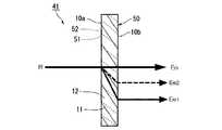
The
The thickness t of the structural
Since the
上記感光性材料からなる基体には、少なくとも一対の面が設けられており、この一対の面のうち一方の面内が光の入射位置とされ、他方の面内が光の出射位置とされている。
また、上記感光性材料からなる基体には、上記の周期的な屈折率分布(周期的構造)の方向が上記基体面の法線に対して斜めとなるように形成されている。詳しくは、一方の面(入射面)10aは第1の領域11と第2の領域12との界面(該界面に平行な方向を仮想線10cにて示している。)に対して所定の角度だけ傾斜しており、他方の面(出射面)10bは第1の領域11と第2の領域12との界面に対して所定の角度だけ傾斜している。The substrate made of the photosensitive material is provided with at least a pair of surfaces, and one of the pair of surfaces serves as a light incident position, and the other surface serves as a light emission position. Yes.
The base made of the photosensitive material is formed so that the direction of the periodic refractive index distribution (periodic structure) is oblique to the normal line of the base surface. Specifically, one surface (incident surface) 10a has a predetermined angle with respect to the interface between the
第1の領域11の屈折率をn1、幅をd1、第2の領域12の屈折率をn2、幅をd2とした場合、n1<n2、n1≠n2であることを必須とするが、d1とd2は、d1=d2であってもd1≠d2であってもよい。 When the refractive index of the
本実施形態の偏光分離素子1は、図1と図2に示すY方向については構造的に一様であり、第1の領域11と第2の領域12との界面(該界面に平行な方向を仮想線10cにて示している。)は、入射光Rの入射方向であるZ方向に対して所定の角度だけ傾斜させている。言い換えれば、上記界面は、X方向に平行な入射側の斜め断面10a及びこれに平行な出射側の斜め断面10bと各々所定の交差角θ1を有するようにしている。The
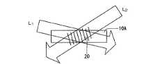
この偏光分離素子1を製造するには、例えば、図3又は図4に示すように光の照射により屈折率が変化する感光性材料10Aに2光束L1、L2を入射し上記材料中で干渉縞20を発生させ、該干渉縞20と上記材料を反応させることで、干渉縞20に対応した周期的な屈折率分布を有する感光性材料からなる基体から構成された構造複屈折体が得られる。詳しくは、干渉縞20に対応する部分には、屈折率が小さい第1の領域11が形成され、干渉縞20以外の部分には第2の領域12が形成される。
なお、図3では、感光性材料10A の一方の側から方向が異なる2光束L1、L2 を出射し、これら2光束L1、L2が感光性材料10A中で交差するように照射している。図4では、感光性材料10A の一方の側から光束L1を出射し、他方の側から光束L1とは方向が異なる光束L2を出射し、これら2光束L1、L2が感光性材料10A中で交差するように照射している。In order to manufacture this
In FIG. 3, two light beams L1 and L2 having different directions are emitted from one side of the
上記感光性材料としては、光重合型のものと架橋型のものがある。光重合型においてはほとんどの材料がバインダーと1種類以上のモノマーとの組み合せからなるが、他に増感剤や光開始剤、その他の添加剤を混ぜているものもある。それらの組成、比率は用途などによって適宜決定される。本実施形態で用いる感光性材料は光重合型の材料でバインダーポリマー、モノマー、開始剤、増感剤等を混合したものであり、青色光から赤色光に対して幅広い感度を有するものである。また、本実施形態で用いる感光性材料としては光の照射により屈折率が変化するフォトポリマー材料を用いてもよい。 The photosensitive material includes a photopolymerization type and a crosslinking type. In the photopolymerization type, most materials consist of a combination of a binder and one or more types of monomers, but there are other materials in which sensitizers, photoinitiators, and other additives are mixed. Their composition and ratio are appropriately determined depending on the application. The photosensitive material used in this embodiment is a photopolymerization type material in which a binder polymer, a monomer, an initiator, a sensitizer, and the like are mixed, and has a wide sensitivity from blue light to red light. In addition, as the photosensitive material used in the present embodiment, a photopolymer material whose refractive index changes upon light irradiation may be used.
本実施形態の偏光分離素子1は上記のような構成とされているので、図1と図2に示すように同図の左方から所定の方向、言い換えれば、Z方向にそって光Rが入射すると、光学的な複屈折性が発生し、入射光RはY方向に偏波した常光E0とX方向に偏波した異常光Ee とに所定の偏光分離角φで分離される。なお、図2中、符号θは、入射光Rの方向と、第1の領域11と第2の領域12との界面とのなす角度である。
本実施形態の偏光分離素子1は、2光束干渉露光法により感光性材料に光の波長以下の周期の屈折率分布を形成するという簡単な方法により製造できるため、コスト高となることがない。
なお、本実施形態の構成では、第1と第2の領域11、12の屈折率の差分が大きくなると、形状複屈折性が大きくなる、上記分離角φはより大きなものとなる。Since the
Since the
In the configuration of the present embodiment, when the difference in refractive index between the first and
なお、上記構造複屈折体10の少なくとも一面に誘電体多層膜等からなる反射防止膜が形成されていてもよい。例えば、このような反射防止膜が構造複屈折体10の入射面10aに形成されていると、この入射面10aを透過する光の強度のロスを抑えることができ、偏光分離素子としての性能が向上できる。また、入射面10aとともに出射面10bにも反射防止膜を形成することにより、構造複屈折体10内での多重反射が抑えられて不必要な干渉光を生じさせることがなくなり偏光分離素子としての性能がさらに向上できるだけでなく、構造複屈折体10の作製時に感光性材料への多重反射による余分な干渉パターンを記録してしまうことがなくなり、偏光分離素子の性能劣化や精度のばらつき等を抑えることができる。
また、構造複屈折体10が感光性材料からなる基体の少なくとも一面に接してこの感光性材料からなる基体の支持するガラス製等の支持基板を有する場合には、この支持基板面に反射防止膜を形成するようにしてもよく、この場合も上記と同様の効果が得られるものである。
また、上記構造複屈折体10の少なくとも一面に可視光を透過するバンドパスフィルタ層が形成されていてもよく、これにより、例えばこの構造複屈折体10をCCDカメラの受光部に配置して用いるような場合に、可視画像以外の不要な帯域の光をカットできるので、このCCDカメラの画質を向上させることができる。An antireflection film made of a dielectric multilayer film or the like may be formed on at least one surface of the structural
Further, when the structural
In addition, a band pass filter layer that transmits visible light may be formed on at least one surface of the structural
(第2の実施形態)
図5は、本発明の第2の実施形態の偏光分離素子の構造を模式的に示す斜視図であり、図6は、図5の偏光分離素子の断面図である。
第2の実施形態の偏光分離素子21が、第1の実施形態の偏光分離素子1と異なるところは、感光性材料からなる基体から構成された構造複屈折体30に、周期的な屈折率分布が複数の方向(図面では2方向)にそれぞれ形成されている点である。
上記感光性材料からなる基体には、第1の実施形態と同様に一方の方向に低屈折率の第1の領域11と、高屈折率の第2の領域12とが交互に形成され、さらに他方の方向に低屈折率の第3の領域31と、この第3の領域より屈折率が高い第4の領域32とが交互に形成されている。(Second Embodiment)
FIG. 5 is a perspective view schematically showing the structure of the polarization separation element according to the second embodiment of the present invention, and FIG. 6 is a cross-sectional view of the polarization separation element in FIG.
The
On the substrate made of the photosensitive material,
また、上記感光性材料からなる基体の他方の方向の周期的な屈折率分布(周期的構造)が上記基体面の法線に対して斜めに形成されている。詳しくは、感光性材料からなる基体の一方の面(入射面)10aは第3の領域31と第4の領域32との界面に対して所定の角度だけ傾斜しており、他方の面(出射面)10bは第3の領域31と第4の領域32との界面に対して所定の角度だけ傾斜している。 Further, a periodic refractive index distribution (periodic structure) in the other direction of the substrate made of the photosensitive material is formed obliquely with respect to the normal line of the substrate surface. Specifically, one surface (incident surface) 10a of the substrate made of a photosensitive material is inclined by a predetermined angle with respect to the interface between the
第3の領域31の屈折率をn3、幅をd3、第4の領域32の屈折率をn4、幅をd4とした場合、n3<n4、n3≠n4であることを必須とするが、d3とd4は、d3=d4であってもd3≠d4であってもよい。When the refractive index of the
第1の領域11及び第3の領域31の屈折率n1、n3と、それらの幅d1、d3はそれぞれ同じ値でなくともよく、第2の領域12及び第4の領域32の屈折率n2、n4と、それらの幅d2、d4についても同様であり、それぞれ同じ値である必要はない。また、それぞれの屈折率分布方向に対応させて入射光Rを等しい角度で分岐させる場合は、n1=n3 、n2=n4、d1=d3、d2=d4とする必要があるが、分岐角度を変えたい場合には屈折率と幅を適宜異ならせることで調整が可能である。ここで、屈折率の変更は露光時の光出力や露光時間などで調整が可能であり、幅の変更は光の波長や2光束の相対角度などで調整が可能である。The refractive indexes n1 and n3 of the
この偏光分離素子21を製造するには、例えば、図3に示すように光の照射により屈折率が変化する感光性材料10Aに2光束L1、L2を入射し上記材料中で干渉縞20を発生させ、該干渉縞20と上記材料を反応させることで、干渉縞20に対応した周期的な屈折率分布(一方の周期的な屈折率分布)を形成する工程後、図7に示すように感光性材料10Aを図示上下方向に延びる軸の周りに所定角度(180度の整数倍を除く)回転させることで光の入射方向を変えて再度2光束L1、L2を入射し上記材料中で干渉縞を発生させ、該干渉縞と上記材料を反応させることで、干渉縞に対応した周期的な屈折率分布(他方の周期的な屈折率分布)を形成する工程を1回以上行うことで多重露光し、複数の方向に周期的な屈折率分布が形成された感光性材料からなる基体から構成された構造複屈折体30が得られる。
また、上記の偏光分離素子の製造方法においては、感光性材料を複数回露光していたが、光束の数を増やし、かつ、これら光束の方向を複数方向とすることで一括で複数方向の屈折率分布を形成する方法でも本実施形態の偏光分離素子21を製造できる。
また、上記感光性材料に複数方向の光を入射させる際、各方向において入射光の波長を変更し、複数の方向に周期的な屈折率分布を形成するとともに複数の方向の周期的な屈折率分布が周期的な屈折率の間隔が異なる感光性材料からなる基体を作製するようにしてもよい。In order to manufacture this
Further, in the above-described method of manufacturing the polarization separation element, the photosensitive material is exposed a plurality of times. However, the number of light beams is increased, and the directions of these light beams are set to a plurality of directions to refract the light in a plurality of directions at once. The
In addition, when light in a plurality of directions is incident on the photosensitive material, the wavelength of the incident light is changed in each direction to form a periodic refractive index distribution in the plurality of directions and a periodic refractive index in the plurality of directions. You may make it produce the base | substrate which consists of a photosensitive material from which the distribution of periodic refractive index differs in distribution.
本実施形態の偏光分離素子は、同じ感光性材料からなる基体中に複数方向の屈折率分布を形成してなる構造複屈折体から構成されたものであるので、図6に示すように同図の左方から所定の方向、言い換えれば、Z方向にそって光Rが入射すると、光学的な複屈折性が発生し、入射光Rは互いに偏波が直交する常光E0と、異常光Ee1、Ee2に分離する。
本実施形態の偏光分離素子によれば、コスト高となることがなく、容易に製造でき、かつ1枚で複数方向に光を分離できる。Since the polarization separation element of the present embodiment is composed of a structural birefringent body in which a refractive index distribution in a plurality of directions is formed in a substrate made of the same photosensitive material, as shown in FIG. When light R is incident along a predetermined direction from the left side, in other words, along the Z direction, optical birefringence occurs, and the incident light R includes normal light E0 and abnormal light E whose polarizations are orthogonal to each other. Separate intoe1 andEe2 .
According to the polarization separation element of this embodiment, it is possible to easily manufacture without increasing the cost, and to separate light in a plurality of directions by one sheet.
図8は、上記のような構成の偏光分離素子21を光学的ローパスフィルタに用いた例を示す図である。図8中、符号35はCCDカメラ、符号36はCCDカメラ35の前方に設けられたレンズであり、これらCCDカメラ35とレンズ36の間に本実施形態の偏光分離素子21が光学的ローパスフィルタとして設けられている。ここでの偏光分離素子21は、入射面10a側がレンズ36側になるように配置されている。
本実施形態の偏光分離素子21が設けられたCCDカメラ35によれば、偏光分離素子が1枚しか設けられていなくても、周期的に並んだ構造の受光部に起因するモアレ縞をぼかすことができ、良好な画像が得られる。FIG. 8 is a diagram illustrating an example in which the
According to the
(第3の実施形態)
図9は、本発明の第3の実施形態の偏光分離素子の構造を模式的に示す断面図である。
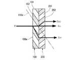
第3の実施形態の偏光分離素子41が、第2の実施形態の偏光分離素子21と異なるところは、感光性材料からなる基体からなる構造複屈折体50に、基体面の法線に対してそれぞれ角度が異なる複数の方向(図面では2方向)の周期的な屈折率分布が形成されている点である。
詳しくは、上記感光性材料からなる基体には、第1や第2の実施形態と同様に一方の方向に低屈折率の第1の領域11と、高屈折率の第2の領域12とが交互に形成され、さらに他方の方向に低屈折率の第3の領域51と、この第3の領域より屈折率が高い第4の領域2とが交互に形成され、これら2方向の周期的な屈折率分布の方向が基体面の法線に対してそれぞれ角度が異なるものである。(Third embodiment)
FIG. 9 is a cross-sectional view schematically showing the structure of a polarization beam splitting element according to the third embodiment of the present invention.
The
Specifically, the substrate made of the photosensitive material includes a
第3の実施形態の偏光分離素子41の製造方法が、第2の実施形態の偏光分離素子21の製造方法と異なるところは、上記感光性材料に入射させる複数方向の光は各方向において入射角度を変更する点である。例えば、図10に示すように上記他方の周期的な屈折率分布を形成するために感光性材料10Aに入射させる2光束L3とL4のうち少なくとも一方の入射角度を、上記一方の周期的な屈折率分布を形成するために感光性材料に入射させた2光束L1、L2の入射角度と異なるようにすればよい。The manufacturing method of the
本実施形態の偏光分離素子41は、上記のような構成としたことにより、基体面の法線に対して複数の角度を成す周期構造が形成されていることとなり、角度が変わることにより複屈折性も変化するので、偏光分離角度を異ならせることができ、光学的ローパスフィルタとして用いた場合にモアレ縞を効果的にぼかすことができる。
なお、複数の方向の周期的な屈折率分布を形成する場合に、本実施形態で説明したように感光性材料に入射させる光束の角度を異ならせる方法と、第2の実施形態(図7参照)で説明したように感光性材料に入射させる光束の入射方向を変化させる方法とを組み合わせるようにしてもよい。Since the
In the case of forming a periodic refractive index distribution in a plurality of directions, as described in the present embodiment, the method of varying the angle of the light beam incident on the photosensitive material and the second embodiment (see FIG. 7). As described in (4), a method of changing the incident direction of the light beam incident on the photosensitive material may be combined.
1,21,41・・・偏光分離素子、10,30,50・・・構造複屈折体、11・・・第1の領域、12・・・第2の領域、20・・・干渉縞、31,51・・・第3の領域、32,52・・・第4の領域、35・・・CCDカメラ、36・・・レンズ、10a・・・入射面、 10b・・・出射面、10c・・・第1の領域と第2の領域との界面に平行な方向、10A・・・感光性材料、E0・・・常光、Ee・・・異常光、L1,L2・・・光束、R・・・入射光、t・・・厚み、φ・・・偏光分離角、θ1・・・交差角。1, 21, 41 ... polarization separation element, 10, 30, 50 ... structural birefringence, 11 ... first region, 12 ... second region, 20 ... interference fringes, 31, 51 ... third region, 32, 52 ... fourth region, 35 ... CCD camera, 36 ... lens, 10a ... entrance surface, 10b ... exit surface, 10c ... first region and a direction parallel to the interface between the second region, 10A ... photosensitivematerial, E 0 ...ordinary, E e ... extraordinarylight, L1, L 2 · · A luminous flux, R: incident light, t: thickness, φ: polarization separation angle, θ1: crossing angle.
Claims (13)
Translated fromJapanesePriority Applications (3)
| Application Number | Priority Date | Filing Date | Title |
|---|---|---|---|
| JP2004070951AJP2005258171A (en) | 2004-03-12 | 2004-03-12 | Polarizing splitting element and its manufacturing method |
| US11/064,697US7466486B2 (en) | 2004-03-12 | 2005-02-23 | Polarization separating element and method of manufacturing the same |
| EP05005044AEP1574896A1 (en) | 2004-03-12 | 2005-03-08 | Polarization separating element and method of manufacturing the same |
Applications Claiming Priority (1)
| Application Number | Priority Date | Filing Date | Title |
|---|---|---|---|
| JP2004070951AJP2005258171A (en) | 2004-03-12 | 2004-03-12 | Polarizing splitting element and its manufacturing method |
Publications (1)
| Publication Number | Publication Date |
|---|---|
| JP2005258171Atrue JP2005258171A (en) | 2005-09-22 |
Family
ID=34824632
Family Applications (1)
| Application Number | Title | Priority Date | Filing Date |
|---|---|---|---|
| JP2004070951AWithdrawnJP2005258171A (en) | 2004-03-12 | 2004-03-12 | Polarizing splitting element and its manufacturing method |
Country Status (3)
| Country | Link |
|---|---|
| US (1) | US7466486B2 (en) |
| EP (1) | EP1574896A1 (en) |
| JP (1) | JP2005258171A (en) |
Cited By (2)
| Publication number | Priority date | Publication date | Assignee | Title |
|---|---|---|---|---|
| JP2008310077A (en)* | 2007-06-15 | 2008-12-25 | Ricoh Co Ltd | Polarization conversion element and laminated polarization conversion element |
| JP2010060587A (en)* | 2008-09-01 | 2010-03-18 | Sony Corp | Polarizing element and method for producing the same |
Families Citing this family (1)
| Publication number | Priority date | Publication date | Assignee | Title |
|---|---|---|---|---|
| EP4038313A4 (en) | 2019-10-03 | 2023-11-22 | RealD Spark, LLC | Illumination apparatus comprising passive optical nanostructures |
Family Cites Families (10)
| Publication number | Priority date | Publication date | Assignee | Title |
|---|---|---|---|---|
| US5161039A (en)* | 1989-07-12 | 1992-11-03 | Board Of Trustees, Leland Stanford Jr. University | Birefringent structures formed by photo-exposure of polymer films and method for fabrication thereof |
| JP3631771B2 (en) | 1993-08-20 | 2005-03-23 | ルビコン株式会社 | Aluminum electrolytic capacitor and manufacturing method thereof |
| US5808798A (en)* | 1996-03-27 | 1998-09-15 | Minnesota Mining And Manufacturing Co. | Nonpolarizing beamsplitter |
| FR2754609B1 (en) | 1996-10-15 | 1998-12-18 | Sextant Avionique | VISUALIZATION PANEL WITH HOLOGRAPHIC BIREFRINGENT FILM COMPENSATION |
| US6424395B1 (en)* | 1998-04-08 | 2002-07-23 | Toppan Printing Co., Ltd. | Light scattering film and liquid crystal display device |
| FR2813127A1 (en) | 2000-08-18 | 2002-02-22 | Thomson Csf | COMPENSATOR FOR LIQUID CRYSTAL DISPLAY DEVICE |
| US20040218271A1 (en)* | 2001-07-18 | 2004-11-04 | Carl Zeiss Smt Ag | Retardation element made from cubic crystal and an optical system therewith |
| JP3979138B2 (en)* | 2001-12-20 | 2007-09-19 | 住友電気工業株式会社 | Optical isolator and polarizer |
| US7072102B2 (en)* | 2002-08-22 | 2006-07-04 | Asml Netherlands B.V. | Methods for reducing polarization aberration in optical systems |
| US20040258355A1 (en)* | 2003-06-17 | 2004-12-23 | Jian Wang | Micro-structure induced birefringent waveguiding devices and methods of making same |
- 2004
- 2004-03-12JPJP2004070951Apatent/JP2005258171A/ennot_activeWithdrawn
- 2005
- 2005-02-23USUS11/064,697patent/US7466486B2/ennot_activeExpired - Fee Related
- 2005-03-08EPEP05005044Apatent/EP1574896A1/ennot_activeWithdrawn
Cited By (2)
| Publication number | Priority date | Publication date | Assignee | Title |
|---|---|---|---|---|
| JP2008310077A (en)* | 2007-06-15 | 2008-12-25 | Ricoh Co Ltd | Polarization conversion element and laminated polarization conversion element |
| JP2010060587A (en)* | 2008-09-01 | 2010-03-18 | Sony Corp | Polarizing element and method for producing the same |
Also Published As
| Publication number | Publication date |
|---|---|
| EP1574896A1 (en) | 2005-09-14 |
| US20050200956A1 (en) | 2005-09-15 |
| US7466486B2 (en) | 2008-12-16 |
Similar Documents
| Publication | Publication Date | Title |
|---|---|---|
| US7995275B2 (en) | Polarization conversion element, polarization conversion optical system and image projecting apparatus | |
| CN104395785B (en) | Optical element, production method for optical element, and optical device | |
| US7301700B2 (en) | Polarization beam splitter and optical system using the same, and image displaying apparatus, using the same | |
| JP2009157043A (en) | Imaging device and imaging equipment having the same | |
| JP2006133403A (en) | Polarization separation element | |
| KR20220061175A (en) | Spectral element array, imaging device and imaging device | |
| JP2002169022A (en) | Optical element, spectroscopic device and integrated optical device using the same | |
| WO2015146506A1 (en) | Phase filter, imaging optical system, and imaging system | |
| CN106358443A (en) | Polarization imaging filter and method for manufacturing same | |
| CN114503538A (en) | Image pickup element and image pickup apparatus | |
| JP2005258171A (en) | Polarizing splitting element and its manufacturing method | |
| JP4345811B2 (en) | Optical element, transfer mold and imaging device | |
| JP5218061B2 (en) | Diffraction type display device, finder device and camera | |
| KR20140097957A (en) | Optical device, solid-state imaging device and method of producing optical device | |
| JP7207883B2 (en) | Optical low-pass filter and imager | |
| KR20010034621A (en) | Hologram polarized light separator | |
| JP2019191310A (en) | Projector and spatial frequency component reduction method using the same | |
| JP2019113816A (en) | Method for manufacturing wire grid polarization element, and substrate for manufacturing wire grid polarization element | |
| JP2004530145A5 (en) | ||
| JP2005062524A (en) | Optical filter and optical instrument | |
| JP6715042B2 (en) | Depolarizer | |
| CN111185677B (en) | Laser device and substrate etching method using the same | |
| JP2005077545A (en) | Polarization conversion optical system, manufacturing method thereof, and liquid crystal display device | |
| JP4943790B2 (en) | Polarization conversion unit and image projection apparatus | |
| JP4926471B2 (en) | Optical element and imaging apparatus having the same |
Legal Events
| Date | Code | Title | Description |
|---|---|---|---|
| A621 | Written request for application examination | Free format text:JAPANESE INTERMEDIATE CODE: A621 Effective date:20060906 | |
| A521 | Written amendment | Free format text:JAPANESE INTERMEDIATE CODE: A821 Effective date:20060907 | |
| A761 | Written withdrawal of application | Free format text:JAPANESE INTERMEDIATE CODE: A761 Effective date:20090612 |