JP2005255389A - Printer - Google Patents
PrinterDownload PDFInfo
- Publication number
- JP2005255389A JP2005255389AJP2004072792AJP2004072792AJP2005255389AJP 2005255389 AJP2005255389 AJP 2005255389AJP 2004072792 AJP2004072792 AJP 2004072792AJP 2004072792 AJP2004072792 AJP 2004072792AJP 2005255389 AJP2005255389 AJP 2005255389A
- Authority
- JP
- Japan
- Prior art keywords
- writing
- recording medium
- speed
- motor
- unit
- Prior art date
- Legal status (The legal status is an assumption and is not a legal conclusion. Google has not performed a legal analysis and makes no representation as to the accuracy of the status listed.)
- Pending
Links
- 230000032258transportEffects0.000claimsdescription63
- 230000010354integrationEffects0.000claimsdescription13
- 238000011161developmentMethods0.000claimsdescription5
- 230000001360synchronised effectEffects0.000claimsdescription5
- 239000003990capacitorSubstances0.000claimsdescription4
- 230000001678irradiating effectEffects0.000claimsdescription2
- 238000004904shorteningMethods0.000abstract1
- 238000004891communicationMethods0.000description14
- 230000003287optical effectEffects0.000description9
- 230000005540biological transmissionEffects0.000description7
- 238000010586diagramMethods0.000description6
- 238000001514detection methodMethods0.000description5
- 239000004973liquid crystal related substanceSubstances0.000description5
- 239000000758substrateSubstances0.000description4
- 239000003086colorantSubstances0.000description3
- 238000012790confirmationMethods0.000description3
- 230000010355oscillationEffects0.000description3
- 230000004044responseEffects0.000description3
- 230000001413cellular effectEffects0.000description2
- 244000145845chatteringSpecies0.000description2
- 210000000078clawAnatomy0.000description2
- 238000000034methodMethods0.000description2
- 230000007723transport mechanismEffects0.000description2
- 230000008859changeEffects0.000description1
- 239000003795chemical substances by applicationSubstances0.000description1
- 230000007423decreaseEffects0.000description1
- 230000003247decreasing effectEffects0.000description1
- 230000000694effectsEffects0.000description1
- 230000007246mechanismEffects0.000description1
- 238000012544monitoring processMethods0.000description1
- 230000002093peripheral effectEffects0.000description1
- 230000008569processEffects0.000description1
- 230000009467reductionEffects0.000description1
- 230000002269spontaneous effectEffects0.000description1
Images


Classifications
- B—PERFORMING OPERATIONS; TRANSPORTING
- B41—PRINTING; LINING MACHINES; TYPEWRITERS; STAMPS
- B41J—TYPEWRITERS; SELECTIVE PRINTING MECHANISMS, i.e. MECHANISMS PRINTING OTHERWISE THAN FROM A FORME; CORRECTION OF TYPOGRAPHICAL ERRORS
- B41J13/00—Devices or arrangements of selective printing mechanisms, e.g. ink-jet printers or thermal printers, specially adapted for supporting or handling copy material in short lengths, e.g. sheets
- B41J13/0009—Devices or arrangements of selective printing mechanisms, e.g. ink-jet printers or thermal printers, specially adapted for supporting or handling copy material in short lengths, e.g. sheets control of the transport of the copy material
- B—PERFORMING OPERATIONS; TRANSPORTING
- B41—PRINTING; LINING MACHINES; TYPEWRITERS; STAMPS
- B41J—TYPEWRITERS; SELECTIVE PRINTING MECHANISMS, i.e. MECHANISMS PRINTING OTHERWISE THAN FROM A FORME; CORRECTION OF TYPOGRAPHICAL ERRORS
- B41J11/00—Devices or arrangements of selective printing mechanisms, e.g. ink-jet printers or thermal printers, for supporting or handling copy material in sheet or web form
- B41J11/36—Blanking or long feeds; Feeding to a particular line, e.g. by rotation of platen or feed roller
- B41J11/42—Controlling printing material conveyance for accurate alignment of the printing material with the printhead; Print registering
- B41J11/425—Controlling printing material conveyance for accurate alignment of the printing material with the printhead; Print registering for a variable printing material feed amount
- B—PERFORMING OPERATIONS; TRANSPORTING
- B41—PRINTING; LINING MACHINES; TYPEWRITERS; STAMPS
- B41J—TYPEWRITERS; SELECTIVE PRINTING MECHANISMS, i.e. MECHANISMS PRINTING OTHERWISE THAN FROM A FORME; CORRECTION OF TYPOGRAPHICAL ERRORS
- B41J2/00—Typewriters or selective printing mechanisms characterised by the printing or marking process for which they are designed
- B41J2/435—Typewriters or selective printing mechanisms characterised by the printing or marking process for which they are designed characterised by selective application of radiation to a printing material or impression-transfer material
- B41J2/447—Typewriters or selective printing mechanisms characterised by the printing or marking process for which they are designed characterised by selective application of radiation to a printing material or impression-transfer material using arrays of radiation sources
- B—PERFORMING OPERATIONS; TRANSPORTING
- B41—PRINTING; LINING MACHINES; TYPEWRITERS; STAMPS
- B41J—TYPEWRITERS; SELECTIVE PRINTING MECHANISMS, i.e. MECHANISMS PRINTING OTHERWISE THAN FROM A FORME; CORRECTION OF TYPOGRAPHICAL ERRORS
- B41J3/00—Typewriters or selective printing or marking mechanisms characterised by the purpose for which they are constructed
- B41J3/36—Typewriters or selective printing or marking mechanisms characterised by the purpose for which they are constructed for portability, i.e. hand-held printers or laptop printers
Landscapes
- Health & Medical Sciences (AREA)
- General Health & Medical Sciences (AREA)
- Toxicology (AREA)
- Printers Or Recording Devices Using Electromagnetic And Radiation Means (AREA)
- Printers Characterized By Their Purpose (AREA)
- Handling Of Sheets (AREA)
- Handling Of Cut Paper (AREA)
- Character Spaces And Line Spaces In Printers (AREA)
- Delivering By Means Of Belts And Rollers (AREA)
- Facsimiles In General (AREA)
Abstract
Description
Translated fromJapanese本発明は、画像が記録される記録媒体を搬送しながらその記録媒体上に画像を書き込むプリンタに関する。 The present invention relates to a printer that writes an image on a recording medium while conveying the recording medium on which the image is recorded.
上記のようなプリンタとして、インスタントフイルムシート上にカラー画像を記録するプリンタがある。このプリンタは、搬送中のインスタントフイルムシートに所定の固定書込点で画像を書き込む固定書込ヘッドを備え、インスタントフイルムシートをモータで所定の副走査方向に送りながら、そのモータの回転に同期した書込指示パルスでその副走査方向に関して、レッド(R),グリーン(G),ブルー(B)の発光色を持つ発光素子からの、画像データに応じた光量をインスタントフイルムシート上に、上記固定書込ヘッドで循環的に書き込むことにより、そのインスタントフイルムシート上にカラー画像を記録する。ここで、何らかの原因で書込指示パルスが発生されなかった場合に、ダミーパルスを発生させるプリンタが提案されている(特許文献1参照)。
従来の、上記特許文献1に提案されたプリンタを含む、画像が記録される記録媒体を搬送しながらその記録媒体に画像を書き込むプリンタでは、記録媒体に十分な露光量を与えるために、記録媒体を所定の速度以下で搬送する必要がある。一方、一連のシーケンスをできるだけ速く終了させたいという要望もある。 In a conventional printer that writes an image onto a recording medium while conveying the recording medium on which an image is recorded, including the printer proposed in
本発明は、上記事情に鑑み、記録媒体上に書き込まれる画像の品質を維持したまま、1枚のプリントに要する時間の短縮化が図られたプリンタを提供することを目的とする。 In view of the above circumstances, an object of the present invention is to provide a printer in which the time required for printing one sheet is shortened while maintaining the quality of an image written on a recording medium.
上記目的を達成する本発明のプリンタは、画像が記録される記録媒体を搬送しながらその記録媒体上に画像を書き込むプリンタにおいて、
搬送中の記録媒体に所定の固定書込点で画像を書き込む固定書込ヘッドと、
記録媒体を所定の搬送開始点から上記固定書込点を通過して所定の搬送終了点まで搬送する媒体搬送部と、
上記搬送開始点にある記録媒体が所定の初期搬送速度で搬送開始され、その記録媒体上の所定の書込開始点が上記固定書込点に達するよりも前に低速の書込搬送速度に変更され、その記録媒体上の所定の書込終了点が上記固定書込点を通過した後にその記録媒体の搬送速度が再び上記書込搬送速度よりも高速の送出搬送速度に変更されるように上記媒体搬送部を制御する搬送制御部とを備えたことを特徴とする。The printer of the present invention that achieves the above object is a printer that writes an image on a recording medium while conveying the recording medium on which the image is recorded.
A fixed writing head for writing an image at a predetermined fixed writing point on a recording medium being conveyed;
A medium transport unit that transports the recording medium from a predetermined transport start point to the predetermined transport end point through the fixed writing point;
The recording medium at the transport start point is transported at a predetermined initial transport speed, and the write start speed on the recording medium is changed to a lower writing transport speed before reaching the fixed writing point. So that after the predetermined writing end point on the recording medium passes through the fixed writing point, the conveying speed of the recording medium is changed again to a sending conveying speed higher than the writing conveying speed. And a conveyance control unit that controls the medium conveyance unit.
本発明のプリンタは、搬送開始点にある記録媒体を所定の初期搬送速度で搬送開始し、その記録媒体上の所定の書込開始点が上記固定書込点に達するよりも前に低速の書込搬送速度に変更し、書込みが終了すると再び高速の送出搬送速度に変更して外部に記録媒体を送出するものであるため、記録媒体は書込みが開始されるまでは高速に搬送され、書込みが開始される直前で低速に搬送されてその記録媒体上に確実に画像が書き込まれ、その後外部に高速に送出される。従って、記録媒体に書き込まれる画像の品質を維持したまま、1枚のプリントに要する時間の短縮化が図られる。 The printer of the present invention starts transporting the recording medium at the transport start point at a predetermined initial transport speed, and writes at a low speed before the predetermined write start point on the recording medium reaches the fixed write point. When the writing is completed, the recording medium is transferred to the outside again and the recording medium is sent to the outside. Therefore, the recording medium is conveyed at a high speed until writing is started. Immediately before the start, the image is conveyed at a low speed and the image is surely written on the recording medium, and then sent to the outside at a high speed. Therefore, it is possible to shorten the time required for printing one sheet while maintaining the quality of the image written on the recording medium.
ここで、上記媒体搬送部は、内蔵電池から電力の供給を受けた直流モータにより記録媒体を搬送するものであって、
上記搬送制御部は、上記内蔵電池からの電力を上記直流モータに直接に供給することにより上記初期搬送速度および上記送出搬送速度を実現し、上記内蔵電池からの電力をその内蔵電池の電圧よりも低い所定電圧に変換して上記直流モータに供給することにより上記書込搬送速度を実現するものであることが好ましい。Here, the medium transport unit transports the recording medium by a DC motor that is supplied with power from the built-in battery,
The transport control unit realizes the initial transport speed and the delivery transport speed by directly supplying power from the built-in battery to the DC motor, and the power from the built-in battery is more than the voltage of the built-in battery. It is preferable that the writing conveyance speed is realized by converting the voltage into a low predetermined voltage and supplying the voltage to the DC motor.
このようにすると、高価なステッピングモータを採用する必要もなく、安価な直流モータで記録媒体に書き込まれる画像の品質を維持したまま、1枚のプリントに要する時間を短縮することができる。 In this way, it is not necessary to employ an expensive stepping motor, and the time required for printing one sheet can be shortened while maintaining the quality of an image written on a recording medium by an inexpensive DC motor.
上記内蔵電池は一般的に1次電池である事が多く、プリント可能枚数を多くするには電池電圧が低くなる電池寿命付近まで使用する必要があり、本発明のような電池電圧よりも低い電圧で書込搬送速度を実現する方法が最も効果的である。 In general, the built-in battery is often a primary battery, and in order to increase the number of printable sheets, it is necessary to use the battery until near the battery life when the battery voltage is low. The method for realizing the writing conveyance speed is the most effective.
また、上記搬送制御部は、抵抗とキャパシタとからなる積分回路を備えて、その積分回路にデューティ比可変のパルス列信号を与え、記録媒体が上記書込搬送速度で搬送されている間、その積分回路による積分で得られた直流電圧に比例した電力を上記直流モータに与えるものであることも好ましい態様である。 The conveyance control unit includes an integration circuit composed of a resistor and a capacitor, gives a pulse train signal having a variable duty ratio to the integration circuit, and integrates the recording medium while the recording medium is conveyed at the writing conveyance speed. It is also a preferred aspect that the DC motor is supplied with power proportional to the DC voltage obtained by integration by the circuit.
このようにすると、安価な積分回路で直流電圧に比例した電力を直流モータに与えることができるため、コストの低減化が図られる。 If it does in this way, since electric power proportional to DC voltage can be given to a DC motor with an inexpensive integration circuit, cost reduction is achieved.
さらに、上記媒体搬送部が、上記直流モータによる駆動を受けて回転し記録媒体を搬送する搬送ローラと、その搬送ローラの回転に同期したパルス列からなるエンコード信号を生成するエンコーダとを備え、
上記搬送制御部が、記録媒体が上記書込搬送速度で搬送されている間は、そのエンコード信号のパルス列が所定の時間間隔で発生されるように上記直流モータの回転速度を制御するものであることも好ましい。Further, the medium transport unit includes a transport roller that rotates by receiving driving by the DC motor and transports the recording medium, and an encoder that generates an encode signal composed of a pulse train synchronized with the rotation of the transport roller,
While the recording medium is being conveyed at the writing conveyance speed, the conveyance control unit controls the rotational speed of the DC motor so that a pulse train of the encode signal is generated at predetermined time intervals. It is also preferable.
このようにすると、直流モータの回転速度を制御するにあたり、簡単な構成で実現することができる。 If it does in this way, in controlling the rotational speed of a DC motor, it can be realized with a simple configuration.
また、露光により潜像が形成されその潜像が現像により顕像化される記録媒体が装填される媒体装填室を備え、
上記媒体搬送部は、上記媒体装填室を上記搬送開始点としてその媒体装填室に装填された記録媒体を搬送するものであり、
上記固定書込ヘッドは、搬送されている途中の記録媒体に複数の色光を循環的に照射することによりその記録媒体に潜像を書き込むものであってもよい。In addition, the image forming apparatus includes a medium loading chamber in which a recording medium on which a latent image is formed by exposure and the latent image is visualized by development is loaded.
The medium transport section transports a recording medium loaded in the medium loading chamber with the medium loading chamber as the transport start point.
The fixed writing head may write a latent image on the recording medium by cyclically irradiating the recording medium being conveyed with a plurality of color lights.
このように構成すると、インスタント写真用のインスタントフイルムシートが積層されたインスタントフイルムパックが装填されるプリンタにおいて、インスタントフイルムシートに書き込まれる画像の品質を維持したまま、1枚のプリントに要する時間の短縮化が図られる。 With this configuration, in a printer loaded with an instant film pack in which instant film sheets for instant photos are stacked, the time required for one print is reduced while maintaining the quality of an image written on the instant film sheet. Is achieved.
本発明のプリンタによれば、記録媒体上に書き込まれる画像の品質を維持したまま、1枚のプリントに要する時間の短縮化が図られる。 According to the printer of the present invention, the time required for printing one sheet can be shortened while maintaining the quality of the image written on the recording medium.
以下、本発明の実施形態について説明する。 Hereinafter, embodiments of the present invention will be described.
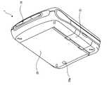
図1は、本発明の一実施形態のプリンタを、斜め前方から見た斜視図である。 FIG. 1 is a perspective view of a printer according to an embodiment of the present invention as viewed obliquely from the front.
このプリンタ1は、画像が記録される記録媒体を搬送しながらその記録媒体上に画像を書き込むプリンタである。詳細には、このプリンタ1は、携帯電話などと組み合わされて使用されるものであって、露光により潜像が形成され送り出しの際に現像剤が展開されて顕像化されるインスタントフイルムシートが複数枚(ここでは10枚として説明する)積層されたインスタントフイルムパックが媒体装填室に装填され、そのインスタントフイルムシートを画像データに応じて露光して外部に送り出しながらそのインスタントフイルムシートに現像剤を展開するものである。このインスタントフイルムシートが本発明にいう記録媒体の一例に相当する。ここでは記録媒体としてインスタントフイルムシートを使用しているが、普通紙を使用するプリンタであっても良い。 The
携帯電話にはIRDA(InfRared Data Association)に準拠した赤外線通信を行なえるものがあり、この赤外線通信を使用して自分の持つ情報を他の情報機器へ送信することができ、カメラ付き携帯電話であれば、画像データをこのプリンタ1に送信することができる。このプリンタ1は、そのカメラ付き携帯電話で撮影された画像を表わす画像データまたはメールなどで携帯電話に送信されてきた画像データが赤外線通信を用いてこのプリンタ1に送信されてきたときに、その画像データに基づいてインスタントフイルムシート上に画像の記録を行なうものであり、さらにその送信された画像データに基づく画像の再記録を、携帯電話から再送信をわざわざ行なわなくても、後述するリピートスイッチを操作するという簡単な操作で別のインスタントフイルムシート上に行なえるものである。 Some mobile phones can perform infrared communication in conformity with IRDA (Infrared Data Association). Using this infrared communication, you can send your information to other information devices. If there is, the image data can be transmitted to the
このプリンタ1は、図1に示すように薄型で軽量かつ小型の構造を有する可搬型のプリンタであり、3V用の一次電池が2個内蔵される。このプリンタ1の筐体1a内にインスタントフイルムパックが装填され、そのインスタントフイルムパック内の、積層された10枚のインスタントフイルムシート一枚一枚に画像の記録が行なわれる。 The
プリンタ1の筐体1aの上面には操作ボタンとして、このプリンタ1の電源の投入および遮断を指示する電源スイッチ(以下、電源SWと記述する)11と、送信された画像データに基づく画像の再記録を行なうためのリピートスイッチ(以下、リピートSWと記述する)12が設けられている。また、筐体1aの上面には、インスタンフイルムシートの残り枚数を示すカウンタ13が設けられている。このカウンタ13は機械式のカウンタであり、未使用のインスタントフイルムパックが装填されると残り枚数が10枚であることを示す数値‘10’が表示される。以下、インスタントフイルムシートに画像の記録が行なわれる度に枚数が減算された残り枚数を示す数値が表示され、10枚目のインスタントフイルムシートに画像の記録が行なわれると残り枚数が0枚であることを示す数値‘0’が表示される。尚、インスタントフイルムパックが抜かれた場合は、何も表示されないブランク状態となる。 On the upper surface of the
また、このプリンタ1の端部には、前述した赤外線通信により送信されてきた画像データを受信するとともに受信された旨を相手側に知らせるための信号を送信する送受信部14が備えられている。 Further, an end portion of the
さらに、このプリンタ1の筐体1aには、電源が投入されると点灯するとともに赤外線通信時に点滅する電源用LED15、赤外線通信においてエラーが発生すると点灯する通信エラー用LED16、および内蔵された電池電圧が低下するとユーザに電池交換を促すために点灯するローバッテリ表示用のLED17が設けられている。 In addition, the
また、プリンタ1の側面には、そのプリンタ1の下面側に設けられた後述するフイルムドアを開放するためのフイルムドア開放スイッチ18が備えられており、コーナー部にはストラップ取付部1bが備えられている。 Further, the side face of the
図2は、図1に示すプリンタにおいて、カメラ付き携帯電話からの画像データに基づいて画像が記録されたインスタントフイルムシートが排出される様子を示す図である。 FIG. 2 is a diagram illustrating a state in which an instant film sheet on which an image is recorded based on image data from a camera-equipped mobile phone is discharged in the printer illustrated in FIG.
カメラ付き携帯電話2の赤外線通信部をプリンタ1の送受信部14に向けた状態で、そのカメラ付き携帯電話2を操作して、カメラ付き携帯電話2で撮影された画像を表わす画像データを赤外線通信を用いてこのプリンタ1に送信する。プリンタ1は、赤外線通信により送信されてきた画像データを受信し、その受信した画像データに基づく潜像の記録を露光によりインスタントフイルムシート1001上に行ないながら、そのインスタントフイルムシート1001を顕像しつつ、プリンタ1の送出口19から外部へ徐々に排出する。その後、リピートSW12が操作されたときにも、その画像と同じ画像の再記録が別のインスタントフイルムシート上に行なわれる。 With the infrared communication unit of the camera-equipped
図3は、図1に示すプリンタの下面側を斜め上方から見た斜視図である。 FIG. 3 is a perspective view of the lower surface side of the printer shown in FIG. 1 as viewed obliquely from above.
このプリンタ1の下面側には、図2に示すフイルムドア開放スイッチ18の操作により開放されるフイルムドア20が設けられており、このフイルムドア20が開けられ、インスタントフイルムパックが媒体装填室に装填される。また、フイルムドア20には、インスタントフイルムパックが装填されているか否かを確認するためのパック在否確認窓20aが設けられている。さらに、フイルムドア20に隣接して、このプリンタ1の電源となる電池を実装するために開放される電池蓋21も設けられている。 A
図4は、図3に示すプリンタの、フイルムドアが開けられた状態の斜視図である。 FIG. 4 is a perspective view of the printer shown in FIG. 3 with the film door opened.
フイルムドア20の内側には、前述したパック在否確認窓20aと、バネ部材20b,20cが設けられており、これらのバネ部材20b,20cによってインスタントフイルムパック内に積層されたインスタントフイルムシートがプリンタ1の上面側に押圧される。 The above-described pack presence /
また、プリンタ1には、インスタントフイルムパックを装填するための媒体装填室22が設けられている。媒体装填室22外の、図4における右側には、後述する画像書込部300(本発明にいう固定書込ヘッドの一例に相当)および媒体搬送部30が設けられている。また、媒体装填室22内の、図4における下方には、インスタントフイルムシートを画像書込部300および媒体搬送部30側に送り出させるための爪(クロー)24が設けられている。このような構成によって、インスタントフイルムパック内のインスタントフイルムシートのうちの、プリンタ1の一番上面側にあるインスタントフイルムシートが爪24で押し上げられて媒体搬送部30で搬送されながら画像書込部300で記録される。 The
図5は、プリンタ内部の制御系統を示す構成ブロック図である。 FIG. 5 is a block diagram showing the internal control system of the printer.
図5の右端側には、図1に示すプリンタ1の模式図が示されており、この右端部を除く全域に、このプリンタ1の制御系統を示す構成が示されている。尚、図5に示す矢印は、このプリンタ1における、制御系統を示す構成要素それぞれの配置関係を示す。 A schematic diagram of the
このプリンタ1には、メイン基板部100と、サブ基板部200と、画像書込部300と、FPI部401と、ENCPI部402と、COUNTPI部403と、カムスイッチ404と、前述した送受信部14に設けられたIrDA送受信部405と、直流モータ406とが備えられている。 The
サブ基板部200には、前述した電源SW11,リピートSW12、および表示用LED部201が備えられている。表示用LED部201には、前述した電源用LED15,通信エラー用LED16,ローバッテリ表示用のLED17、およびカウンタ13の裏側に設けられたカウンタバックライト用のLED(図示せず)が備えられている。 The
画像書込部300は、本発明にいう固定書込ヘッドの一例に相当し、この画像書込部300には、光ガイドや液晶シャッタ(LCS)等を有する光ヘッド部301と、その光ヘッド部301とメイン基板部100とを接続するフレキシブルケーブル302,303と、フレキシブルケーブル303に実装されたレッド(R),グリーン(G),ブルー(B)の発光色を持つ発光素子(LED)304,305,306とが備えられている。この画像書込部300は、詳細は後述するが、搬送途中のインスタントフイルムシートに、後述する書込指示パルスに同期してLED304,305,306からのR,G,Bの3つの色光を循環的に照射することにより、そのインスタントフイルムシートに潜像を書き込む。また、プリンタ1には、3V用の一次電池407が2個内蔵される。 The
以下、メイン基板部100について説明する。メイン基板部100には、直列接続された一次電池407からの6Vの電源電圧VBが印加される。このメイン基板部100には、MPU(Micro Processor Unit)101と、発振子102と、リセット回路103と、フラッシュメモリ(FLASH)104と、SDRAM105とが備えられている。 Hereinafter, the
MPU101は、このプリンタ1の動作を統括的に制御する。 The
発振子102は、所定の周波数の発振信号を生成してMPU101に動作用のクロック信号として供給する。 The
リセット回路103は、MPU101の初期化を行なうためのリセット信号を出力する。 The
フラッシュメモリ104は、不揮発性のメモリであり、このフラッシュメモリ104には、プリンタ1固有の機構等に依存して定まる個体差調整用の調整値等が記憶される。 The
SDRAM105は、揮発性のメモリであり、このSDRAM105には、カメラ付き携帯電話2からの画像データ等が記憶される。 The
また、このメイン基板部100には、6Vの電源電圧VBを入力して、2.5Vの電圧を出力する電源部106、3.3Vの電圧を出力する電源部107、および15Vの電圧を出力するDC/DCコンバータ108が備えられている。さらに、MPU101からの指示を受けてこれら電源部106,107,DC/DCコンバータ108を制御する電源制御部109も備えられている。ここで、2.5Vの電圧はMPU101に供給されるとともに3.3Vの電圧はMPU101以外の周辺回路に供給される。また、15Vの電圧は、後述するLCD駆動用として用いられる。 The
このプリンタ1では、一次電池407の長寿命化を図るために、低消費電力モードであるスタンバイモードを有するMPU101を備え、電源SW12が押された場合であっても、MPU101は、初期処理が終了した時点でスタンバイモードとなる。この状態で外部から赤外線通信が行なわれると、スタンバイモードから通常の動作モードに移行してインスタントフイルムシートに画像を記録し、速やかに通常の動作モードからスタンバイモードに移行する。また、リピートSW12が押された場合もインスタントフイルムシートに画像を記録した後はスタンバイモードになる。さらに、MPU101が、各部に対して必要な動作時のみ電力を供給するように、電源制御部109を介して電源部106,107,DC/DCコンバータ108を制御する。このようにすることにより、内蔵された一次電池407で長期に渡ってこのプリンタ1を使用することができる。 In order to extend the life of the
さらに、メイン基板部100には、BC部110と、TPG部111と、温度検出部112と、発振子113と、IrDA/LCS制御部114と、ヘッドLED駆動部115とが備えられている。 Further, the
BC部110は、一次電池407の電源電圧VBが所定の値よりも低下したか否かをチェックする。MPU101は、このチェック結果を参照して一次電池407の電源電圧VBが所定の値よりも低下していると判定した場合は、ユーザに電池交換を促すためにローバッテリ表示用のLED17を点灯する。 The
TPG部111は、DC/DCコンバータ108から出力される15Vの電圧をオン,オフする。 The
温度検出部112は、画像書込部300の温度を検出する。MPU101は、この温度検出部112からの検出信号に応じて光学ヘッド部301内の液晶シャッタの各シャッタ部のシャッタスピード等を制御する。 The
発振子113は、所定の周波数の発振信号を生成してIrDA/LCS制御部114に供給する。 The
IrDA/LCS制御部114は、発振子113からの発振信号に基づいてIrDA送受信部405および光ヘッド部301を制御する。IrDA送受信部405には赤外線通信を行なうための投光素子および受光素子が備えられており、IrDA/LCS制御部114は、上記受光素子で光電変換されたデータをMPU101に送ったり、MPU101からその旨を外部の機器に知らせるためのデータを上記投光素子経由で外部に送信したりする。また、IrDA/LCS制御部114は、MPU101からの指示に基づいて、フレキシブルケーブル302を介して光ヘッド部301に備えられた液晶シャッタを制御する。 The IrDA /
ヘッドLED駆動部115は、MPU101の指示に基づいた電流を、フレキシブルケーブル303を経由してLED304,305,306に流すことにより、それらLED304,305,306を駆動する。 The head
本実施形態のプリンタ1は、インスタントフイルムシートを直流モータ406で所定の副走査方向(インスタントフイルムシートが送り出される方向)に送りながら、そのインスタントフイルムシート上にその副走査方向に関しR,G,Bの3色の色について循環的に書き込むとともに、その副走査方向に交わる主走査方向については、その主走査方向に並ぶ全画素について、同時に同じ色の書き込みを行なうことにより、そのインスタントフイルムシート上にカラー画像を記録するプリンタである。 The
カラー画像を記録するにあたり、画像書込部300を構成する光学ヘッド部301には、フレキシブルケーブル302を介してIrDA/LCS制御部114から画像データに応じた制御信号が供給される。この制御信号は光学ヘッド部301内の液晶シャッタの各シャッタ部のシャッタスピードを制御するものである。この各シャッタ部のシャッタスピードが画像データに応じて制御され、フレキシブルケーブル303に備えられたLED304,305,306からのRGBそれぞれに対応する光がインスタントフイルムシート上に照射され、インスタントフイルムシートの幅方向に多数の光点(ドット)からなる潜像が記録される。この幅方向つまり一次元的に各シャッタ部が配列されている方向が、主走査方向である。従って、この各シャッタ部が主走査方向に電子的に走査されて1ライン分の光点(全画素)がインスタントフイルムシートシート上に記録される。この光学ヘッド部301の電子走査によってインスタントフイルムシートの主走査方向に多数のドットからなる光点が記録される。また、上述したように、本実施形態では、直流モータ406によりインスタントフイルムシートシートが副走査方向に送られている。従って、副走査方向についても画像書込部300によって多数のドット毎に光点が順次記録されていくこととなる。 In recording a color image, a control signal corresponding to image data is supplied from the IrDA /
さらに、メイン基板部100には、PI駆動部116が備えられている。このPI駆動部116は、FPI部401,ENCPI部402,COUNTPI部403を駆動する。ここで、FPI部401,ENCPI部402,COUNTPI部403について説明する。 Further, the
FPI部401は、インスタントフイルムシートの有無を検出して、後述するフイルム信号FILM_PIを出力するためのフォトインタラプタである。このFPI部401は、インスタントフイルムシートがインスタントフイルムパックに収容されている初期状態では、フイルム信号FILM_PIとして‘H’レベルが出力される。また、直流モータ406が回転してインスタントフイルムシートが搬送されてその先端が検出されるとフイルム信号FILM_PIは‘H’レベルから‘L’レベルに変化する。さらに、そのインスタントフイルムシートが搬送され続けて後端が検出されるとフイルム信号FILM_PIは‘L’レベルから‘H’レベルに変化する。 The
ENCPI部402は、直流モータ406の回転に同期したパルス列からなる、後述するエンコード信号ENCを出力するためのフォトインタラプタである。 The
COUNTPI部403は、カウンタ13がリセット状態(インスタントフイルムパックが抜かれた状態)を検知するためのフォトインタラプタである。 The
また、メイン基板部100には、カムスイッチ404が接続されている。このカムスイッチ404は、このプリンタ1の搬送機構における初期位置をモニタするためのスイッチであり、初期位置ではこのカムスイッチ404からカムスイッチ信号CAMSWとして‘H’レベルが出力され、直流モータ406の回転に伴い搬送機構が初期位置から外れるとカムスイッチ信号CAMSWは‘H’レベルから‘L’レベルに変化する。 A cam switch 404 is connected to the
さらに、メイン基板部100には、モータ駆動部117が備えられている。このモータ駆動部117およびMPU101が、本発明にいう搬送制御部の役割を担うものである。 Further, the
本実施形態のプリンタ1では、一次電池407が使用される。一般に、一次電池は、自然放電を防止するためにその内部抵抗は大きい。このため、一次電池内部に流れる電流変動がそのままその一次電池から出力される電圧の変動として現れる。また、本実施形態のプリンタ1では、直流モータ406が使用される。従って、インスタントフイルムシート1001への書込みにあたり、そのインスタントフイルムシート1001に十分な露光量を安定して与えるためには、インスタントフイルムシート1001を所定の速度以下で搬送する必要がある。また、インスタントフイルムシート1001上に画像を書き込むための時間を短くする必要もある。 In the
これらを実現するために、本実施形態では、本発明にいう搬送制御部の役割を担うモータ駆動部117およびMPU101が、一次電池407からの電力を直流モータ406に直接に供給することにより、所定の初期搬送速度および高速の送出搬送速度を実現し、一次電池407からの電力をその一次電池407の電圧(ここでは6V)よりも低い所定電圧(ここでは4V)に変換して直流モータ407に供給することにより低速の書込搬送速度を実現する。さらに、モータ駆動部117およびMPU101は、インスタントフイルムシート1001が上記書込搬送速度で搬送されている間は、エンコード信号のパルス列が所定の時間間隔で発生されるように直流モータ406の回転速度を制御する。尚、このような、モータ駆動部117およびMPU101による制御については後述する。 In order to realize these, in the present embodiment, the
図6は、媒体搬送部の一部の構成を示す断面図である。 FIG. 6 is a cross-sectional view illustrating a partial configuration of the medium transport unit.
図6の左側が、このプリンタ1の上面である。この媒体搬送部30には、インスタントフイルムパック25から送り出されたインスタントフイルムシート1001の両側部を挟んでそのインスタントフイルムシート1001を搬送する一対の搬送ローラ31,32が備えられている。搬送ローラ32はバネ部材35_1で搬送ローラ31側に付勢されている。また、この媒体搬送部30には、インスタントフイルムシート1001の現像溜まり1001aを押し潰して現像剤を展開する一対の展開ローラ33,34が備えられている。展開ローラ34はバネ部材35_2で展開ローラ33側に付勢されている。さらに、媒体搬送部30には、一対の搬送ローラ31,32と一対の展開ローラ33,34との間に位置して展開中の現像剤を制御するための制御板36,37と、インスタントフイルムシート1001を案内するためのフイルム案内フレーム38が備えられている。また、インスタントフイルムパック25の出口近傍には、画像書込部300が設けられている。この画像書込部300は、搬送中のインスタントフイルムシート1001に所定の固定書込点Pfで画像を書き込む。 The left side of FIG. 6 is the upper surface of the
媒体搬送部30は、インスタントフイルムシート1001を所定の搬送開始点Psから固定書込点Pfを通過して所定の搬送終了点Peまで搬送する。 The
ここで、上記モータ駆動部117およびMPU101は、搬送開始点Psにあるインスタントフイルムシート1001が所定の初期搬送速度で搬送開始され、そのインスタントフイルムシート1001上の所定の書込開始点が固定書込点Pfに達するよりも前に低速の書込搬送速度に変更され、そのインスタントフイルムシート1001上の所定の書込終了点が固定書込点Pfを通過した後にインスタントフイルムシート1001の搬送速度が再び上記書込搬送速度よりも高速の送出搬送速度に変更されるように媒体搬送部30を制御する。このように、本実施形態のプリンタ1は、搬送開始点Psにあるインスタントフイルムシート1001を所定の初期搬送速度で搬送開始し、そのインスタントフイルムシート1001上の所定の書込開始点が上記固定書込点Pfに達するよりも前に低速の書込搬送速度に変更し、書込みが終了すると再び高速の送出搬送速度に変更して外部にインスタントフイルムシート1001を送出するものであるため、インスタントフイルムシート1001は書込みが開始されるまでは高速に搬送され、書込みが開始される直前で低速に搬送されてそのインスタントフイルムシート1001上に確実に画像が書き込まれ、その後外部に高速に送出される。従って、インスタントフイルムシート1001に書き込まれる画像の品質を維持したまま、1枚のプリントに要する時間の短縮化が図られる。 Here, the
図7は、媒体搬送部の斜視図である。 FIG. 7 is a perspective view of the medium transport unit.
図7に示す媒体搬送部30には、上述した一対の搬送ローラ31,32および一対の展開ローラ33,34が備えられている。また、この媒体搬送部30には、直流モータ406の回転駆動力を搬送ローラ31,32および展開ローラ33,34に伝達するためのギア列39が備えられている。さらに、媒体搬送部30には、投光素子および受光素子からなる透過型のフォトインタラプタであるENCPI402および円盤状の部材41を有するエンコーダ40が備えられている。円盤状の部材41は、搬送ローラ31に取り付けられている。円盤状の部材41には多数の溝穴が設けられており、この円盤状の部材41が搬送ローラ31の回転に伴って回転することにより、ENCPI部402が、これら多数の溝穴を介して投光素子からの光を受光素子で受光することにより、搬送ローラ31の回転に同期したパルス列からなるエンコード信号を生成する。 The
図8は、図5に示すモータ駆動部の回路を示す図、図9は、図8に示すモータ駆動部およびMPUにおけるタイミングチャートである。 FIG. 8 is a diagram showing a circuit of the motor drive unit shown in FIG. 5, and FIG. 9 is a timing chart in the motor drive unit and MPU shown in FIG.
図8に示すモータ駆動部117には、制御部117_1と、抵抗素子117_2aおよびコンデンサ素子117_2bからなる積分回路117_2と、接点117_3a,117_3b,117_3cを有するスイッチ回路117_3とが備えられている。スイッチ回路117_3は、MPU101からのモータ制御信号CONT_MTVにより切り換えられる。 The
制御部117_1の入力IN1には、MPU101からモータ駆動信号DMDRVが入力される。また、積分回路117_2には、MPU101から直流モータ406の回転を一定に制御するためのデューティ比可変のパルス信号SET_MTVDMDRV信号が入力される。さらに、スイッチ回路117_3の接点117_3bには、一次電池407からの6Vの電源電圧VBが印加される。 The motor drive signal DMDRV is input from the
図9に示すように、初期状態では、MPU101からのモータ駆動信号DMDRVは‘L’レベルにある。また、カムスイッチ404からのカムスイッチ信号CAMSWは‘H’レベルにある。さらに、FPI部401からのフイルム信号FILM_PIは、‘H’レベルにある。また、MPU101からのモータ制御信号CONT_MTVは‘H’レベルにある。これにより、スイッチ回路117_3の接点117_3bと接点117_3cが接続されており、制御部117_1の入力IN2には、6Vの電源電圧VBが入力されている。 As shown in FIG. 9, in the initial state, the motor drive signal DMDRV from the
ここで、MPU101によりモータ駆動信号DMDRVが‘L’レベルから‘H’レベルに変化する。制御部117_1は、この‘H’レベルを受けて、入力IN2に入力されている6Vの電源電圧VBを出力OUTからモータ406に向けて出力する。モータ406には、この6Vの電源電圧VBが印加されるため、高速に回転する。これにより、インスタントフイルムシートが初期搬送速度で高速に搬送開始される。また、モータ406の回転に同期してエンコード信号ENCが出力される。さらに、MPU101から所定のデューティ比を有するパルス信号SET_MTVが積分回路117_2に入力される。積分回路117_2は、このパルス信号SET_MTVのデューティ比に応じた制御電圧を生成する。 Here, the motor drive signal DMDRV is changed from the “L” level to the “H” level by the
モータ駆動信号DMDRVが‘L’レベルから‘H’レベルに変化した時点から時間t1経過後、カムスイッチ信号CAMSWが‘H’レベルから‘L’レベルに変化する。また、モータ406が高速に回転しているため、このモータ406の回転に同期して出力されるエンコード信号ENCの周期は比較的短い。 The cam switch signal CAMSW changes from the “H” level to the “L” level after the elapse of time t1 from the time when the motor drive signal DMDRV changes from the “L” level to the “H” level. Further, since the
時間t1よりも長い時間t2経過後、インスタントフイルムシートの先端が検出されてフイルム信号FILM_PIが‘H’レベルから‘L’レベルに変化する。これを受けて、MPU101は、モータ406の回転をモニタして、そのモータ406の回転を一定に制御するためにパルス信号SET_MTVのデューティ比を変更するというフィードバック制御を行なう。このフィードバック制御されたパルス信号SET_MTVが積分回路117_2に入力される。積分回路117_2は、このデューティ比に応じた制御電圧を生成する。また、MPU101は、時間t2が経過した時点から、フイルム信号FILM_PIが有するチャタリング時間t3よりも長い時間t4経過後、モータ制御信号CONT_MTVを‘H’レベルから‘L’レベルに変化させる。これにより、スイッチ回路117_3の接点117_3aと接点117_3cが接続されて、制御部117_1の入力IN2には、積分回路117_2により定まる6Vの電源電圧VBよりも低い制御電圧が入力される。制御部117_1は、この制御電圧を出力OUTからモータ406に向けて出力する。モータ406には、この制御電圧が印加されるため、モータ406は低速で回転する。従って、インスタントフイルムシートは低速の書込搬送速度に変更されて搬送される。 After the elapse of time t2 longer than time t1, the leading edge of the instant film sheet is detected, and the film signal FILM_PI changes from the “H” level to the “L” level. In response to this, the
上記時間t2経過した時点から上記時間t4よりも長い時間t6経過後、液晶シャッタ制御(LCS制御)が行なわれて、前述したようにしてインスタントフイルムシート上に書き込みが行なわれる。LCS制御が終了すると、MPU101は、パルス信号SET_MTVの出力を停止する。また、MPU101は、モータ制御信号CONT_MTVを‘L’レベルから‘H’レベルに変化させる。すると、モータ406に6Vの電源電圧VBが印加されてモータ406が高速に回転する。これにより、インスタントフイルムシートは再び高速の送出搬送速度に変更されて搬送される。さらに、インスタントフイルムシートの後端が検出されてフイルム信号FILM_PIが‘L’レベルから‘H’レベルに変化する。その後、カムスイッチ信号CAMSWが‘L’レベルから‘H’レベルに変化する。MPU101は、このカムスイッチ信号CAMSWが有するチャタリング時間t7経過後、モータ駆動信号DMDRVを‘H’レベルから‘L’レベルに変化させる。このようにして、プリンタ1の一連の動作が終了する。 After a time t6 longer than the time t4 from the time t2 elapses, liquid crystal shutter control (LCS control) is performed, and writing is performed on the instant film sheet as described above. When the LCS control ends, the
尚、本実施形態では、本発明を、インスタントフイルムを用いたプリンタに適用した例で説明したが、これに限られるものではなく、本発明は、画像が記録される記録媒体をモータで所定の副走査方向に送りながらその記録媒体上にその副走査方向に関し複数の色について循環的に書き込むことによりその記録媒体上にカラー画像を記録するプリンタであればよい。 In the present embodiment, the present invention has been described with reference to an example in which the present invention is applied to a printer using an instant film. However, the present invention is not limited to this, and the present invention is not limited to this. Any printer that records a color image on a recording medium by cyclically writing a plurality of colors in the sub-scanning direction while feeding in the sub-scanning direction may be used.
1 プリンタ
1a 筐体
2 カメラ付き携帯電話
11 電源スイッチ(電源SW)
12 リピートスイッチ(リピートSW)
13 カウンタ
14 送受信部
15 電源用LED
16 通信エラー用LED
17 ローバッテリ表示用のLED
18 フイルムドア開放スイッチ
1b ストラップ取付部
19 送出口
20 フイルムドア
20a パック在否確認窓
20b,20c バネ部材
21 電池蓋
22 媒体装填室
23 搬送ローラ
24 爪(クロー)
25 インスタントフイルムパック
30 媒体搬送部
31,32 搬送ローラ
35_1,35_2 バネ部材
33,34 展開ローラ
36,37 制御板
38 フイルム案内フレーム
39 ギア列
40 エンコーダ
41 円盤状の部材
100 メイン基板部
101 MPU
102,113 発振子
103 リセット回路
104 フラッシュメモリ
105 SDRAM
106,107 電源部
108 DC/DCコンバータ
109 電源制御部
110 BC部
111 TPG部
112 温度検出部
114 IrDA/LCS制御部
115 ヘッドLED駆動部
116 PI駆動部
117 モータ駆動部
117_1 制御部
117_2 積分回路
117_2a 抵抗素子
117_2b コンデンサ素子
117_3 スイッチ回路
117_3a,117_3b,117_3c 接点
200 サブ基板部
201 表示用LED部
300 画像書込部
301 光ヘッド部
302,303 フレキシブルケーブル
304,305,306 発光素子(LED)
401 FPI部
402 ENCPI部
403 COUNTPI部
404 カムスイッチ
405 IrDA送受信部
406 モータ
407 一次電池
1001 インスタントフイルムシート
1001a 現像溜まりDESCRIPTION OF
12 Repeat switch (repeat SW)
13
16 Communication error LED
17 LED for low battery display
18 Film
25
102, 113
106, 107
401
Claims (5)
Translated fromJapanese搬送中の記録媒体に所定の固定書込点で画像を書き込む固定書込ヘッドと、
記録媒体を所定の搬送開始点から前記固定書込点を通過して所定の搬送終了点まで搬送する媒体搬送部と、
前記搬送開始点にある記録媒体が所定の初期搬送速度で搬送開始され、該記録媒体上の所定の書込開始点が前記固定書込点に達するよりも前に低速の書込搬送速度に変更され、該記録媒体上の所定の書込終了点が前記固定書込点を通過した後に該記録媒体の搬送速度が再び前記書込搬送速度よりも高速の送出搬送速度に変更されるように前記媒体搬送部を制御する搬送制御部とを備えたことを特徴とするプリンタ。In a printer that writes an image on a recording medium while conveying the recording medium on which the image is recorded,
A fixed writing head for writing an image at a predetermined fixed writing point on a recording medium being conveyed;
A medium transport unit that transports the recording medium from a predetermined transport start point to the predetermined transport end point through the fixed writing point;
The recording medium at the conveyance start point is started to be conveyed at a predetermined initial conveyance speed, and the writing writing speed on the recording medium is changed to a low writing conveyance speed before the predetermined writing start point reaches the fixed writing point. And after the predetermined writing end point on the recording medium passes through the fixed writing point, the recording medium conveyance speed is again changed to a sending conveyance speed higher than the writing conveyance speed. A printer comprising: a conveyance control unit that controls the medium conveyance unit.
前記搬送制御部は、前記内蔵電池からの電力を前記直流モータに直接に供給することにより前記初期搬送速度および前記送出搬送速度を実現し、前記内蔵電池からの電力を該内蔵電池の電圧よりも低い所定電圧に変換して前記直流モータに供給することにより前記書込搬送速度を実現するものであることを特徴とする請求項1記載のプリンタ。The medium conveying unit conveys a recording medium by a DC motor that is supplied with electric power from a built-in battery,
The transport control unit realizes the initial transport speed and the delivery transport speed by directly supplying power from the built-in battery to the DC motor, and the power from the built-in battery is more than the voltage of the built-in battery. 2. The printer according to claim 1, wherein the writing conveyance speed is realized by converting the voltage into a low predetermined voltage and supplying the voltage to the DC motor.
前記搬送制御部が、記録媒体が前記書込搬送速度で搬送されている間は、該エンコード信号のパルス列が所定の時間間隔で発生されるように前記直流モータの回転速度を制御するものであることを特徴とする請求項1記載のプリンタ。The medium transport unit includes a transport roller that rotates by receiving driving by the DC motor and transports a recording medium, and an encoder that generates an encode signal composed of a pulse train synchronized with the rotation of the transport roller,
The conveyance control unit controls the rotation speed of the DC motor so that the pulse train of the encode signal is generated at predetermined time intervals while the recording medium is conveyed at the writing conveyance speed. The printer according to claim 1.
前記媒体搬送部は、前記媒体装填室を前記搬送開始点として該媒体装填室に装填された記録媒体を搬送するものであり、
前記固定書込ヘッドは、搬送されている途中の記録媒体に複数の色光を循環的に照射することにより該記録媒体に潜像を書き込むものであることを特徴とする請求項1記載のプリンタ。A medium loading chamber in which a recording medium on which a latent image is formed by exposure and the latent image is visualized by development is loaded;
The medium transport unit transports a recording medium loaded in the medium loading chamber with the medium loading chamber as the transport start point.
2. The printer according to claim 1, wherein the fixed writing head writes a latent image on the recording medium by cyclically irradiating the recording medium being conveyed with a plurality of color lights.
Priority Applications (2)
| Application Number | Priority Date | Filing Date | Title |
|---|---|---|---|
| JP2004072792AJP2005255389A (en) | 2004-03-15 | 2004-03-15 | Printer |
| US11/078,488US20050200673A1 (en) | 2004-03-15 | 2005-03-14 | Printer |
Applications Claiming Priority (1)
| Application Number | Priority Date | Filing Date | Title |
|---|---|---|---|
| JP2004072792AJP2005255389A (en) | 2004-03-15 | 2004-03-15 | Printer |
Publications (1)
| Publication Number | Publication Date |
|---|---|
| JP2005255389Atrue JP2005255389A (en) | 2005-09-22 |
Family
ID=34918631
Family Applications (1)
| Application Number | Title | Priority Date | Filing Date |
|---|---|---|---|
| JP2004072792APendingJP2005255389A (en) | 2004-03-15 | 2004-03-15 | Printer |
Country Status (2)
| Country | Link |
|---|---|
| US (1) | US20050200673A1 (en) |
| JP (1) | JP2005255389A (en) |
Cited By (3)
| Publication number | Priority date | Publication date | Assignee | Title |
|---|---|---|---|---|
| WO2018008229A1 (en)* | 2016-07-07 | 2018-01-11 | 富士フイルム株式会社 | Printer, imaging device equipped with printer, and printing method |
| WO2018008191A1 (en)* | 2016-07-07 | 2018-01-11 | 富士フイルム株式会社 | Film conveying device, printer, imaging device equipped with printer, and film conveying method |
| US12285959B2 (en) | 2022-04-06 | 2025-04-29 | David AMEGASHIE | Ultra-thin portable printer |
Families Citing this family (1)
| Publication number | Priority date | Publication date | Assignee | Title |
|---|---|---|---|---|
| JP6553814B2 (en)* | 2016-07-07 | 2019-08-07 | 富士フイルム株式会社 | Encoder signal processing apparatus, printer, imaging apparatus with printer, and encoder signal processing method |
Family Cites Families (20)
| Publication number | Priority date | Publication date | Assignee | Title |
|---|---|---|---|---|
| DE3882189T2 (en)* | 1987-04-03 | 1994-02-17 | Toyo Seikan Kaisha Ltd | METHOD FOR MULTICOLOR PRINTING OF METAL CONTAINERS AND METAL SHEETS. |
| US5602571A (en)* | 1990-03-14 | 1997-02-11 | Canon Kabushiki Kaisha | Sheet feeding apparatus and recording system with it |
| FR2665862B1 (en)* | 1990-08-20 | 1993-12-10 | Seikosha Co Ltd | MATRIX PRINTER. |
| JP3228476B2 (en)* | 1990-09-21 | 2001-11-12 | キヤノン株式会社 | Recording device |
| US5245447A (en)* | 1991-05-20 | 1993-09-14 | Xerox Corporation | Indexing mechanism for compact scanner |
| US5515087A (en)* | 1993-12-02 | 1996-05-07 | Hewlett-Packard Company | Remaining battery capacity determination method and apparatus |
| US5835107A (en)* | 1994-06-06 | 1998-11-10 | Asahi Kogaku Kogyo Kabushiki Kaisha | Printer with battery discharge device |
| US5940105A (en)* | 1996-01-26 | 1999-08-17 | Canon Kabushiki Kaisha | Motor drive controlling method for an image forming apparatus and motor drive controlling apparatus in the image forming apparatus using the method |
| GB9625284D0 (en)* | 1996-12-04 | 1997-01-22 | Canon Kk | A data processing method and apparatus for identifying a classification to which data belongs |
| US5806993A (en)* | 1997-03-18 | 1998-09-15 | Comtec Information Systems, Inc. | Portable interactive miniature printer |
| SG82608A1 (en)* | 1998-04-15 | 2001-08-21 | Canon Kk | Feeding apparatus, printing apparatus and feeding control method |
| US6056454A (en)* | 1998-10-05 | 2000-05-02 | Gerber Technology, Inc. | Method and apparatus for printing on a continuously moving sheet of work material |
| AUPP702198A0 (en)* | 1998-11-09 | 1998-12-03 | Silverbrook Research Pty Ltd | Image creation method and apparatus (ART79) |
| JP4553441B2 (en)* | 2000-03-10 | 2010-09-29 | 富士フイルム株式会社 | Mobile communication terminal |
| JP2002067392A (en)* | 2000-08-31 | 2002-03-05 | Citizen Watch Co Ltd | Optical printer |
| US20030122957A1 (en)* | 2001-12-31 | 2003-07-03 | Emme Niels Peter | Mobile terminal with digital camera and method of capturing images |
| AUPS048302A0 (en)* | 2002-02-13 | 2002-03-07 | Silverbrook Research Pty. Ltd. | Methods and systems (ap79) |
| JP3687634B2 (en)* | 2002-07-26 | 2005-08-24 | ブラザー工業株式会社 | Printer |
| US6783290B2 (en)* | 2002-08-05 | 2004-08-31 | Pitney Bowes Inc. | Method and system for high speed digital metering using low velocity print technology |
| JP4069794B2 (en)* | 2003-04-28 | 2008-04-02 | セイコーエプソン株式会社 | Recorded material transport device |
- 2004
- 2004-03-15JPJP2004072792Apatent/JP2005255389A/enactivePending
- 2005
- 2005-03-14USUS11/078,488patent/US20050200673A1/ennot_activeAbandoned
Cited By (3)
| Publication number | Priority date | Publication date | Assignee | Title |
|---|---|---|---|---|
| WO2018008229A1 (en)* | 2016-07-07 | 2018-01-11 | 富士フイルム株式会社 | Printer, imaging device equipped with printer, and printing method |
| WO2018008191A1 (en)* | 2016-07-07 | 2018-01-11 | 富士フイルム株式会社 | Film conveying device, printer, imaging device equipped with printer, and film conveying method |
| US12285959B2 (en) | 2022-04-06 | 2025-04-29 | David AMEGASHIE | Ultra-thin portable printer |
Also Published As
| Publication number | Publication date |
|---|---|
| US20050200673A1 (en) | 2005-09-15 |
Similar Documents
| Publication | Publication Date | Title |
|---|---|---|
| JP3882346B2 (en) | Printer | |
| JP2010060978A (en) | Methods and devices for detecting and restoring connection abnormality in process cartridge, and image forming apparatus | |
| JP2007203633A (en) | Printer and printing method | |
| US20070013939A1 (en) | Printer | |
| JP2005255389A (en) | Printer | |
| JP2005300838A (en) | Printer | |
| US9030684B2 (en) | Image forming apparatus, control method of image forming apparatus, and storage medium | |
| JP4339218B2 (en) | Image recording device | |
| WO2018008229A1 (en) | Printer, imaging device equipped with printer, and printing method | |
| JP2007015227A (en) | Printer | |
| JP2007130877A (en) | Printer | |
| JP2005280872A (en) | Printer | |
| CN100440055C (en) | printer | |
| JP4078097B2 (en) | Power transmission device and image forming apparatus | |
| JP2005254652A (en) | Printer | |
| JP2005254651A (en) | Printer | |
| JP2007206432A (en) | Printer | |
| JP2005288962A (en) | Printer | |
| JP2007021967A (en) | Printer | |
| US20060256060A1 (en) | Drive apparatus and printer | |
| JP2006078842A (en) | Image recording apparatus | |
| JP4296125B2 (en) | Printer | |
| JP2006082338A (en) | Image recorder | |
| JP2007118430A (en) | Printer | |
| JP2006088498A (en) | Image recorder |
Legal Events
| Date | Code | Title | Description |
|---|---|---|---|
| A621 | Written request for application examination | Free format text:JAPANESE INTERMEDIATE CODE: A621 Effective date:20060523 | |
| A711 | Notification of change in applicant | Free format text:JAPANESE INTERMEDIATE CODE: A712 Effective date:20061212 | |
| A977 | Report on retrieval | Free format text:JAPANESE INTERMEDIATE CODE: A971007 Effective date:20080421 | |
| A131 | Notification of reasons for refusal | Free format text:JAPANESE INTERMEDIATE CODE: A131 Effective date:20080430 | |
| A02 | Decision of refusal | Free format text:JAPANESE INTERMEDIATE CODE: A02 Effective date:20080902 |