JP2005255037A - Electronic control device for vehicle - Google Patents
Electronic control device for vehicleDownload PDFInfo
- Publication number
- JP2005255037A JP2005255037AJP2004070991AJP2004070991AJP2005255037AJP 2005255037 AJP2005255037 AJP 2005255037AJP 2004070991 AJP2004070991 AJP 2004070991AJP 2004070991 AJP2004070991 AJP 2004070991AJP 2005255037 AJP2005255037 AJP 2005255037A
- Authority
- JP
- Japan
- Prior art keywords
- command
- electronic control
- vehicle
- calculation
- microcomputer
- Prior art date
- Legal status (The legal status is an assumption and is not a legal conclusion. Google has not performed a legal analysis and makes no representation as to the accuracy of the status listed.)
- Granted
Links
- 230000005856abnormalityEffects0.000claimsabstractdescription28
- 230000005540biological transmissionEffects0.000claimsdescription17
- 238000001514detection methodMethods0.000claimsdescription14
- 238000012544monitoring processMethods0.000abstractdescription9
- 238000000034methodMethods0.000description30
- 238000004891communicationMethods0.000description14
- 230000002159abnormal effectEffects0.000description9
- 238000012545processingMethods0.000description8
- 238000010586diagramMethods0.000description3
- 230000000694effectsEffects0.000description2
- 230000007257malfunctionEffects0.000description2
- 230000002093peripheral effectEffects0.000description2
- 230000007423decreaseEffects0.000description1
- 230000001934delayEffects0.000description1
- 230000003111delayed effectEffects0.000description1
- 238000004519manufacturing processMethods0.000description1
- 238000012986modificationMethods0.000description1
- 230000004048modificationEffects0.000description1
- 238000012806monitoring deviceMethods0.000description1
- 230000002265preventionEffects0.000description1
- 230000001360synchronised effectEffects0.000description1
Images


Classifications
- B—PERFORMING OPERATIONS; TRANSPORTING
- B62—LAND VEHICLES FOR TRAVELLING OTHERWISE THAN ON RAILS
- B62D—MOTOR VEHICLES; TRAILERS
- B62D5/00—Power-assisted or power-driven steering
- B62D5/04—Power-assisted or power-driven steering electrical, e.g. using an electric servo-motor connected to, or forming part of, the steering gear
- B62D5/0457—Power-assisted or power-driven steering electrical, e.g. using an electric servo-motor connected to, or forming part of, the steering gear characterised by control features of the drive means as such
- B62D5/0481—Power-assisted or power-driven steering electrical, e.g. using an electric servo-motor connected to, or forming part of, the steering gear characterised by control features of the drive means as such monitoring the steering system, e.g. failures
- B62D5/0493—Power-assisted or power-driven steering electrical, e.g. using an electric servo-motor connected to, or forming part of, the steering gear characterised by control features of the drive means as such monitoring the steering system, e.g. failures detecting processor errors, e.g. plausibility of steering direction
- B—PERFORMING OPERATIONS; TRANSPORTING
- B62—LAND VEHICLES FOR TRAVELLING OTHERWISE THAN ON RAILS
- B62D—MOTOR VEHICLES; TRAILERS
- B62D5/00—Power-assisted or power-driven steering
- B62D5/04—Power-assisted or power-driven steering electrical, e.g. using an electric servo-motor connected to, or forming part of, the steering gear
- B62D5/0457—Power-assisted or power-driven steering electrical, e.g. using an electric servo-motor connected to, or forming part of, the steering gear characterised by control features of the drive means as such
- B—PERFORMING OPERATIONS; TRANSPORTING
- B62—LAND VEHICLES FOR TRAVELLING OTHERWISE THAN ON RAILS
- B62D—MOTOR VEHICLES; TRAILERS
- B62D6/00—Arrangements for automatically controlling steering depending on driving conditions sensed and responded to, e.g. control circuits
- G—PHYSICS
- G05—CONTROLLING; REGULATING
- G05B—CONTROL OR REGULATING SYSTEMS IN GENERAL; FUNCTIONAL ELEMENTS OF SUCH SYSTEMS; MONITORING OR TESTING ARRANGEMENTS FOR SUCH SYSTEMS OR ELEMENTS
- G05B9/00—Safety arrangements
- G05B9/02—Safety arrangements electric
Landscapes
- Engineering & Computer Science (AREA)
- Chemical & Material Sciences (AREA)
- Combustion & Propulsion (AREA)
- Transportation (AREA)
- Mechanical Engineering (AREA)
- Physics & Mathematics (AREA)
- General Physics & Mathematics (AREA)
- Automation & Control Theory (AREA)
- Power Steering Mechanism (AREA)
- Steering Control In Accordance With Driving Conditions (AREA)
- Safety Devices In Control Systems (AREA)
Abstract
Description
Translated fromJapanese本発明は、車両用電子制御装置に関するもので、特に車両用電子制御装置に含まれるマイコン監視装置に関するものである。 The present invention relates to an electronic control device for a vehicle, and more particularly to a microcomputer monitoring device included in the electronic control device for a vehicle.
マイクロコンピュータ制御装置は、制御信号を出力して所定の負荷を制御するマイクロコンピュータ(以下略称:マイコン)と、このマイコンの異常動作状態を検出し、リセット信号を出力してマイコンをリセットするウオッチドッグ回路と、このウオッチドッグ回路のリセット信号に応じて、フェイル信号を出力するフェイルセーフ回路と、このフェイルセーフ回路のフェイルセーフ信号に応じて、マイコンの制御信号をフェイルセーフ側に切り換える信号切換回路とを備え、マイコンのプログラム命令が実行される際のマシンサイクルに同期した信号等を発生させ、該信号が所定の時間発生しない場合はマイコンの動作異常と判定する方式(以下略称:ランパルス方式)が知られている(特許文献1参照)。 The microcomputer control device outputs a control signal to control a predetermined load, and a microcomputer (hereinafter abbreviated as “microcomputer”), detects an abnormal operation state of the microcomputer, outputs a reset signal, and resets the microcomputer. A fail-safe circuit that outputs a fail signal in response to a reset signal of the watchdog circuit, and a signal switching circuit that switches the microcomputer control signal to the fail-safe side in accordance with the fail-safe signal of the fail-safe circuit A method (hereinafter abbreviated as a ramp pulse method) that generates a signal synchronized with a machine cycle when a microcomputer program instruction is executed and determines that the microcomputer does not operate abnormally when the signal does not occur for a predetermined time It is known (see Patent Document 1).
ランパルス方式によるマイコンの監視は、マイコンの暴走検出の効果がある程度期待できるが、マイコンは暴走していないがマイコン内部の演算機能が異常となる場合においてはマイコンの動作異常を検出できず、誤った演算値でそのまま制御を実行してしまい、制御対象機器の誤動作を引き起こすこともある。この問題を解決するために、複数のマイコンを用いて演算結果を相互比較する方式もあるがコストが高くなり製品の競争力が低下してしまう。 The microcomputer monitoring by the ramp pulse method can expect the effect of microcomputer runaway detection to some extent, but if the microcomputer does not run away but the calculation function inside the microcomputer becomes abnormal, it cannot detect the malfunction of the microcomputer and is wrong. The control is executed as it is with the calculated value, which may cause malfunction of the device to be controlled. In order to solve this problem, there is a method of using a plurality of microcomputers to compare the calculation results with each other, but the cost increases and the competitiveness of the product decreases.
また、ネットワーク接続された複数の電子制御装置で構成され、電子制御装置が協調して制御を行なう場合、特許文献1の例のようにランパルス方式でマイコンを監視する方法では、ランパルスは常時出力する必要があるため、通信トラフィックが増大して通信データの衝突あるいは遅延が生ずるため通信線を共用することができず、ランパルス専用の通信線を設ける必要があり、これもコストアップ要因となる。 Further, when the electronic control device is configured by a plurality of network-connected electronic control devices, and the electronic control devices perform coordinated control, the run pulse is always output in the method of monitoring the microcomputer by the run pulse method as in the example of
上記問題を背景として、本発明の課題は、ネットワーク接続された電子制御装置のマイコンの演算機能が正常に動作しているか否かを確実に監視できる安価な車両用電子制御装置を提供することを目的とする。 Against the background of the above problems, an object of the present invention is to provide an inexpensive vehicle electronic control device that can reliably monitor whether or not the calculation function of the microcomputer of the network-connected electronic control device is operating normally. Objective.
本発明は、上記課題を解決するための車両用電子制御装置を提供するものである。即ち、請求項1によれば、指令値の演算を行なう少なくとも1個の指令装置と、アクチュエータの駆動を行なう少なくとも1個の駆動装置とが通信可能に接続され、駆動装置は指令装置から受信した指令値に基づいてアクチュエータの駆動指令を行なう車両用電子制御装置であって、駆動装置は指令装置に対し所定の演算命令を送信し、指令装置は駆動装置に対し演算命令に応じた演算結果を返送し、駆動装置は返送された演算結果に基づいて指令装置の異常を検出することを特徴とする車両用電子制御装置として構成される。 The present invention provides a vehicular electronic control device for solving the above-described problems. That is, according to
上記構成によって、ネットワーク接続された電子制御装置の演算機能が正常に動作しているか否かを確実に監視することができる。また、指令装置および駆動装置というように装置の役割を分けることで、駆動装置が自らへの指令値を送ってくる指令装置を監視するという合理的な構成をとることができる。さらに、ランパルス方式のように別個にランパルス用の通信線を設ける必要もなく、製造コストは上昇しない。 With the above configuration, it is possible to reliably monitor whether the arithmetic function of the electronic control device connected to the network is operating normally. Further, by separating the roles of the devices such as the command device and the drive device, it is possible to adopt a rational configuration in which the drive device monitors the command device that sends the command value to itself. Further, it is not necessary to separately provide a communication line for the ramp pulse as in the ramp pulse method, and the manufacturing cost does not increase.
請求項2によれば、本発明の車両用電子制御装置において、駆動装置による指令装置の異常検出は、所定の周期で実施する構成とすることができる。 According to the second aspect of the present invention, in the vehicle electronic control device of the present invention, the abnormality detection of the command device by the drive device can be performed at a predetermined cycle.
本発明の異常検出の処理は、システムのフェールセーフ処置に許容される時間内に完了する必要があるが、一方で指令装置あるいは駆動装置の通常の制御処理に影響を及ぼさないように実施する必要がある。通常は割り込み処理を用いるが、本異常検出処理に要する時間が長くなると、割り込み時間が長くなり通常の制御処理が遅延する等の影響を及ぼすため、このような場合には通常の制御処理に影響のないように、一回あたりの割り込み許容時間に収まるよう処理を分割して本異常検出処理の周期を設定してもよい。また、複数の指令装置に対して本異常検出処理を行なう場合には、時分割方式を用い本異常検出処理を行なう構成をとる。本構成によって、本異常検出処理の指令装置あるいは駆動装置の制御処理全体に対する占有率を増大させず、通常の制御処理に影響を及ぼすことなく本異常検出処理を行なうことが可能となる。 The abnormality detection process of the present invention needs to be completed within the time allowed for the fail-safe treatment of the system, but on the other hand, it must be performed so as not to affect the normal control process of the command device or the drive device. There is. Normally, interrupt processing is used. However, if the time required for this abnormality detection processing becomes longer, the interruption time becomes longer and the normal control processing is delayed. For this reason, the normal control processing is affected. In order to avoid this, the period of the abnormality detection process may be set by dividing the process so as to be within the allowable interrupt time per time. Further, when performing the abnormality detection process for a plurality of command devices, a configuration is adopted in which the abnormality detection process is performed using a time division method. With this configuration, it is possible to perform the abnormality detection process without increasing the occupation ratio of the control apparatus or the drive device in the abnormality detection process with respect to the entire control process and without affecting the normal control process.
請求項3によれば、本発明の車両用電子制御装置において、駆動装置による指令装置の異常検出は、アクチュエータへの駆動指令を行なう前に実施する構成をとることができる。指令装置からの指令値に基づいてアクチュエータへの駆動指令を行なった後に該指令装置の異常が検出された場合、既に異常な指令値によってアクチュエータへが駆動してしまい、アクチュエータおよびその周辺回路機器の故障等が発生することも有り得る。本発明の構成では、指令値を受信する前、あるいは指令値を受信してからアクチュエータへの駆動指令を行なう間に本異常検出処理を行なうので、異常な指令値によってアクチュエータを駆動することもなく、アクチュエータおよびその周辺回路機器の故障等が発生することもない。 According to the third aspect of the present invention, in the vehicle electronic control device of the present invention, the abnormality detection of the command device by the drive device can be performed before the drive command to the actuator is issued. If an abnormality of the command device is detected after a command to drive the actuator based on the command value from the command device, the actuator has already been driven by the abnormal command value, and the actuator and its peripheral circuit devices A failure or the like may occur. In the configuration of the present invention, since this abnormality detection processing is performed before receiving the command value or while receiving the command value and issuing the drive command to the actuator, the actuator is not driven by the abnormal command value. In addition, failure of the actuator and its peripheral circuit equipment does not occur.
請求項4によれば、本発明の車両用電子制御装置において、駆動装置が複数の指令装置を対象として演算命令を送信する場合、対象となる指令装置への送信順序および指令装置に対する演算命令の送信回数を駆動装置の状態に応じて設定する構成をとることができる。本構成によって、例えば、指令装置からの指令値の送信周期に応じて演算命令の送信周期を変更したり、車両用電子制御装置全体の制御状況によって演算命令を送信する対象となる指令装置を選択することが可能となる。よって、適切なタイミングで精度よく指令装置の異常検出を行なうことができる。 According to the fourth aspect of the present invention, in the vehicle electronic control device of the present invention, when the drive device transmits a calculation command for a plurality of command devices, the transmission order to the target command device and the calculation command for the command device are It is possible to adopt a configuration in which the number of transmissions is set according to the state of the driving device. With this configuration, for example, the command instruction transmission device can be selected according to the transmission status of the command value from the command device, or the calculation command can be transmitted according to the control status of the entire vehicle electronic control device. It becomes possible to do. Therefore, it is possible to accurately detect the abnormality of the command device at an appropriate timing.
請求項5によれば、本発明の車両用電子制御装置において、駆動装置として、運転者のステアリング動作に基づいて、モータを通電駆動してステアリング機構に操舵補助トルクを与える車両における電動パワーステアリング装置を用いる構成をとることができる。 According to the fifth aspect of the present invention, in the vehicle electronic control device according to the present invention, the electric power steering device in the vehicle that applies a driving assisting torque to the steering mechanism by energizing the motor based on the steering operation of the driver as the driving device. The structure using can be taken.
車両では、例えば走行系の指令装置および駆動装置をネットワーク接続し、車両の走行状態に応じて指令装置が電動パワーステアリング装置などの各駆動装置に車両の走行制御を分担して行なわせる協調制御方式が採られることがある。本発明の構成によって、電動パワーステアリング装置が指令装置の故障を検出することで、異常な指令値に基づくステアリング機構の駆動を行なうことを防止できるため、車両の挙動が異常になることを未然に防止することができる。 In a vehicle, for example, a traveling system command device and a drive device are connected to a network, and the command device shares the vehicle drive control with each drive device such as an electric power steering device in accordance with the running state of the vehicle. May be adopted. With the configuration of the present invention, it is possible to prevent the steering mechanism from being driven based on an abnormal command value when the electric power steering device detects a failure of the command device, so that the behavior of the vehicle becomes abnormal in advance. Can be prevented.
ネットワーク接続された電子制御装置のマイコンの演算機能が正常に動作しているか否かを確実に監視できる安価な車両用電子制御装置を提供するという目的を、駆動用電子制御装置が指令用制御装置の演算機能を監視する方法によって実現した。 For the purpose of providing an inexpensive vehicle electronic control device that can reliably monitor whether the computing function of the microcomputer of the network-connected electronic control device is operating normally, the drive electronic control device is a command control device. It was realized by the method of monitoring the calculation function.
以下、本発明の実施の形態である車両用電子制御装置について、図面を用いて説明する。
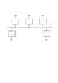
図1は、車両用電子制御装置の全体構成図である。本発明の指令装置であるレーンキープ指令ユニット31,前方車両自動追尾指令ユニット32,自動駐車指令ユニット33と本発明の駆動装置である電動パワーステアリング装置の制御ユニット(以下、EPS−ECUと略称する,EPS:Electronic Power Steering,ECU:Electronic Control Unit)13,伝達比可変操舵装置の制御ユニット(以下、VGRS−ECUと略称する,VGRS:Variable Gear Ratio Steering)22とが通信バス41を介して相互に通信可能に接続されている。Hereinafter, an electronic control device for a vehicle which is an embodiment of the present invention will be described with reference to the drawings.
FIG. 1 is an overall configuration diagram of a vehicle electronic control device. A lane keep
レーンキープ指令ユニット31は接続されている前方監視カメラ11(図3参照)の撮影した画像情報および車両の走行状態に基づいて、走行中の車線を維持するために必要な演算を行ない、その演算結果を指令値としてEPS−ECU13あるいはVGRS−ECU22に送信する。また、前方車両自動追尾指令ユニット32は接続されている前方監視レーダ12(図3参照)によって検出された前方車両との車間距離情報および車両の走行状態に基づいて、該車間距離を維持するために必要な演算を行ない、その演算結果を指令値として送信する。さらに、自動駐車指令ユニット33は図示しない後方監視カメラの撮影した画像情報に基づいて、所定の駐車位置に車両を動かすために必要な演算を行ない、その演算結果を指令値として送信する。なお、車両の走行状態は、車両の速度,EPS−ECU13あるいはVGRS−ECU22から送られる操舵ハンドル110の操舵状態などのパラメータがあるが、用いるパラメータに制約を設けるものではない。 The lane
EPS−ECU13あるいはVGRS−ECU22は、レーンキープ指令ユニット31,前方車両自動追尾指令ユニット32,および自動駐車指令ユニット33から送信されてきた指令値に基づいて操舵に関する制御を行なう。また、これら指令ユニットに現在の制御の状態を送る。 The EPS-
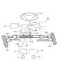
図3を用いて電動パワーステアリング装置および伝達比可変操舵装置の構成について説明する。電動パワーステアリング装置では、操舵ハンドル110が操舵軸(ステアリングシャフト)112aに接続されて、操舵軸112aの下端は運転者の操舵ハンドル110の動きを検出するトルクセンサ111に接続されており、ピニオンシャフト(ステアリングシャフト)112bの上端がトルクセンサ111に接続されている。また、ピニオンシャフト112bの下端には、ピニオン112cが設けられ、ピニオン112cがラックバー118に噛合されている。更に、ラックバー118の両端には、ナックルアーム122,122を介して操舵輪124,124が接続されている。また、ラックバー118には、EPSアクチュエータ115がピニオン115aを介して取り付けられている。なお、EPSアクチュエータ115は、ラックバー118に同軸的に取り付ける方法を採ってもよい。 The configuration of the electric power steering device and the variable transmission ratio steering device will be described with reference to FIG. In the electric power steering apparatus, the
トルクセンサ111およびEPSアクチュエータ115は、EPS−ECU13に接続されている。EPS−ECU13には、図示しないCPU,RAM,ROM,入出力インターフェースであるI/Oおよびこれらの構成を接続するバスライン等を含むマイコン13aが備えられているが、すでに公知のものであるので、その詳しい説明については割愛する。 The
EPS−ECU13においてEPS制御プログラムを実行することにより、各指令ユニットから送られてくる指令値およびトルクセンサ111で検出されたトルクに対応したEPSアクチュエータ115で発生させる駆動トルクを算出し、算出した駆動トルクを発生させるための電圧をEPSアクチュエータ115に印加する。詳しくは、トルクセンサ111がステアリングシャフトにかかる操舵トルクを検出し、検出された操舵トルクに応じてEPSアクチュエータ115に供給する電流値を決定し、決定された電流値によりEPSアクチュエータ115を駆動して、ステアリングシャフトにかかるトルクを補助する。 By executing the EPS control program in the EPS-
伝達比可変操舵装置では、操舵ハンドル110が操舵軸112aに接続されて、この操舵軸112aには運転者の操舵ハンドル110の動きを検出する操舵角センサ211が接続されており、さらにVGRSアクチュエータ212が接続されている。 In the variable transmission ratio steering apparatus, a
操舵角センサ211およびVGRSアクチュエータ212は、VGRS−ECU22に接続されている。VGRS−ECU22には、CPU,RAM,ROM,I/Oおよびこれらの構成を接続するバスライン等を含むマイコンが備えられているが、すでに公知のものであるので、その詳しい説明については割愛する。 The
VGRS−ECU22においてVGRS制御プログラムを実行することにより、各指令ユニットから送られてくる指令値および操舵角センサ211で検出された操舵角に対応したVGRSアクチュエータ212で発生させる舵角比を算出し、算出した舵角比を発生させるための電圧をVGRSアクチュエータ212に印加する。なお、転舵角検知センサが車両の転舵輪の転舵角を検知し、VGRSアクチュエータ212が分割された操舵ハンドル(ステアリング)110側の操舵軸(ステアリングシャフト)112aと転舵輪側のステアリングシャフトとの間の回転角を電動モータにより相対的に変化させる。 By executing the VGRS control program in the VGRS-
以下、本発明の電子制御装置における監視方法を、駆動装置として電動パワーステアリング装置を例に挙げて説明する。伝達比可変操舵装置の場合でも同様であるため説明を割愛する。また、駆動装置としてアンチロックブレーキ装置,横滑り防止装置,アクティブ後輪操舵装置(4WS)を用いてもよい。同様に、指令装置にレーンキープ指令ユニット31,前方車両自動追尾指令ユニット32,および自動駐車指令ユニット33以外の装置を用いてもよい。 Hereinafter, a monitoring method in the electronic control device of the present invention will be described by taking an electric power steering device as an example of a drive device. Since the same applies to the transmission ratio variable steering device, the description is omitted. Further, an anti-lock brake device, a skid prevention device, or an active rear wheel steering device (4WS) may be used as a drive device. Similarly, devices other than the lane keep
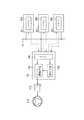
図2において、EPS−ECU13に含まれるマイコン13aから、レーンキープ指令ユニット31に含まれるマイコン31a,前方車両自動追尾指令ユニット32に含まれるマイコン32b,および自動駐車指令ユニット33に含まれるマイコン33cが正しい演算を行なっているかどうかをチェックするための演算命令が送られる。マイコン31a,マイコン32b,およびマイコン33cでは送られてきた演算命令に基づく演算を行ない、その結果をEPS−ECU13へは該演算命令に対する演算結果が返送される。そして、マイコン13aが予め図示しないROM等に記憶している演算結果と、該返送された演算結果とを比較してマイコン31a,マイコン32b,およびマイコン33cの異常を検出する。 In FIG. 2, a
駆動装置であるEPS−ECU13(マイコン13a)から送られる演算命令は、通信バス41のデータ伝送量を著しく増大させないため、演算命令番号および該演算命令番号に対応する演算パラメータおよび正しい演算結果が図示しないROMあるいはRAM等の記憶媒体に記憶されている。一方、指令装置(レーンキープ指令ユニット31,前方車両自動追尾指令ユニット32,および自動駐車指令ユニット33)には、該演算命令番号に対応する演算命令が図示しないROMあるいはRAM等の記憶媒体に記憶されている。 Since the calculation command sent from the EPS-ECU 13 (
そして、EPS−ECU13からは演算命令番号および演算パラメータが各指令ユニットへ送られる。各指令ユニットは該演算命令番号および演算パラメータに基づく演算を行ない、その演算結果をEPS−ECU13へ返送する。EPS−ECU13は返送されてきた演算結果と演算命令番号に対応する正しい演算結果とを比較することで各指令ユニットの異常を検出する。 Then, the EPS-
図5にEPS−ECU13が行なう、レーンキープ指令ユニット31(マイコン31a),前方車両自動追尾指令ユニット32(マイコン32b),および自動駐車指令ユニット33(マイコン33c)との通信のタイミングチャートを示す。ステップ1ではマイコン31aへ演算命令を送信する。ステップ2ではマイコン31aからの演算結果を受信してマイコン31aの異常判定を行なうとともにマイコン32bへ演算命令を送信する。ステップ3ではマイコン32bからの演算結果を受信してマイコン32bの異常判定を行なうとともにマイコン33cへ演算命令を送信する。次のステップ(図示せず)ではマイコン33cからの演算結果を受信してマイコン33cの異常判定を行なうとともにマイコン31aへ演算命令を送信する。 FIG. 5 shows a timing chart of communication with the lane keep command unit 31 (
上記の通信をT2(ms)間隔で繰り返し行ない、最後のステップNではマイコン33cからの演算結果を受信してマイコン33cの異常判定を行なうのみで、マイコン31aへは演算命令を送信しない。これらステップ1からステップNまでの処理を1サイクルとし、1サイクルの周期をT1(ms)としている。上記構成のように、時分割形式(T2間隔)で複数の指令ユニットの演算命令を送信しているため、一度に全ての指令ユニットへ演算命令を送信する方式に比べ、1回あたりの処理時間が短くなり、EPS−ECU13通常処理への影響を最小限に抑えることができる。 The above communication is repeated at intervals of T2 (ms). In the final step N, only the operation result from the
図5の例では、EPS−ECU13(マイコン13a)からの演算命令の送信順は、レーンキープ指令ユニット31(マイコン31a),前方車両自動追尾指令ユニット32(マイコン32b),自動駐車指令ユニット33(マイコン33c)の順に繰り返しそれぞれ同じ回数行なっているが、車両の速度,ステアリング操舵角度などの車両の状態(即ち、制御上の優先度)に応じて演算命令の送信順を変更したり、周期T1あたりの送信回数を可変とする方法をとってもよい。例えば、奇数ステップではマイコン31aに演算命令を送り、偶数ステップではマイコン32bおよびマイコン33cに対して交互に演算命令を送るという方法が挙げられる。 In the example of FIG. 5, the order of transmission of calculation commands from the EPS-ECU 13 (
また、周期T1は、レーンキープ指令ユニット31,前方車両自動追尾指令ユニット32,および自動駐車指令ユニット33からの異常な指令値によってEPSアクチュエータ115が駆動されないように値が設定される。これは、例えば、マイコン13aがレーンキープ指令ユニット31からの指令値を受信して該指令値に基づいてアクチュエータ115を駆動する前に、レーンキープ指令ユニット31のマイコン31aの異常判定処理を必ず行なうようにするためである。 The period T1 is set so that the
よって、周期T1は、各指令ユニットから指令値が送られてくる周期と同じ周期あるいは短い周期とすればよい。また、アクチュエータ115を駆動した後に各指令ユニットに演算指令を送り、各指令ユニットが次の指令値と該演算指令に対する演算結果とを同時に返送する方法を採ってもよい。 Therefore, the cycle T1 may be set to the same cycle as the cycle in which the command value is sent from each command unit or a short cycle. Alternatively, after the
図6は、図5のタイミングチャートに基づいて行なわれる異常判定処理のフロー図である。まず、EPS−ECU13の起動時に各部の初期設定を行なうための初期化処理を行なう(S1)。次に、通信バスに初期化信号を送信し、該初期化信号に応答するユニット(本実施例では、レーンキープ指令ユニット31,前方車両自動追尾指令ユニット32,および自動駐車指令ユニット33)を認識する(S2)。 FIG. 6 is a flowchart of the abnormality determination process performed based on the timing chart of FIG. First, when EPS-
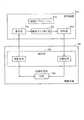
次に、レーンキープ指令ユニット31の監視を行なう。まず、図4の駆動装置(EPS−ECU13)のマイコン13aの通信部13eを介して演算要求を指令装置(レーンキープ指令ユニット31)のマイコン31aに送る(S3)。マイコン31aの受信部31bで演算要求を受信すると、演算タスク実行部31cにおいて該演算要求に対する演算を行ない、該演算結果を送信部31dを介してマイコン13aに返送する。 Next, the lane keep
マイコン13aは通信部13eを介して演算結果を受信すると、マイコン13aが予め図示しないROM等に記憶している演算結果あるいは、マイコン13aが該演算命令に基づく演算結果と受信した演算結果とを比較判定部13dにおいて比較する(S4)。比較の結果、両者が一致する(レーンキープ指令ユニット31における演算結果が正しい,S5:YES)場合は、異常処理要求フラグをオフ状態のままとして次のステップS7へ進む。一方、両者が一致しない(レーンキープ指令ユニット31における演算結果が正しくない,S5:No)場合は、異常処理要求フラグをオン状態とする(S6)。 When the
上記S3〜S4〜S5,S6と同様の手順で、前方車両自動追尾指令ユニット32の監視(S7),および自動駐車指令ユニット33の監視(S8)を行なう。 The front vehicle automatic
レーンキープ指令ユニット31,前方車両自動追尾指令ユニット32,および自動駐車指令ユニット33のうち、いずれのユニットの演算結果とも正常な場合(S9:NO)、通常の制御出力すなわちレーンキープ指令ユニット31,前方車両自動追尾指令ユニット32,および自動駐車指令ユニット33の指令値に基づいてEPSアクチュエータ115の駆動制御を行なう(S10)。一方、いずれかのユニットの演算結果に異常がある場合(S9:YES)、異常のあるユニットからの指令値を用いずにEPSアクチュエータ115の駆動制御を行なう(S11)。 When the calculation results of any of the lane keep
レーンキープ指令ユニット31,前方車両自動追尾指令ユニット32,および自動駐車指令ユニット33のうち、全てのユニットの演算結果とも異常の場合は、EPS−ECU13は独立した制御装置としてトルクセンサ111で検出される操舵トルクに基づいてEPSアクチュエータ115で発生させる駆動トルクを算出しEPSアクチュエータ115の駆動制御を行なう。 If the calculation results of all of the lane keep
以上、本発明の実施の形態を説明したが、これらはあくまで例示にすぎず、本発明はこれらに限定されるものではなく、特許請求の範囲の趣旨を逸脱しない限りにおいて、当業者の知識に基づく種々の変更が可能である。 Although the embodiments of the present invention have been described above, these are merely examples, and the present invention is not limited to these embodiments, and the knowledge of those skilled in the art can be used without departing from the spirit of the claims. Various modifications based on this are possible.
13 電動パワーステアリング装置の制御ユニット(EPS−ECU,駆動装置)
22 伝達比可変操舵装置の制御ユニット(VGRS−ECU,駆動装置)
31 レーンキープ指令ユニット(指令装置)
32 前方車両自動追尾指令ユニット(指令装置)
33 自動駐車指令ユニット(指令装置)
41 通信バス13 Control unit of electric power steering device (EPS-ECU, drive device)
22 Control unit of variable transmission ratio steering device (VGRS-ECU, drive device)
31 Lane Keep Command Unit (Command Device)
32 Front vehicle automatic tracking command unit (command device)
33 Automatic parking command unit (command device)
41 Communication bus
Claims (5)
Translated fromJapanese前記駆動装置は前記指令装置に対し所定の演算命令を送信し、
前記指令装置は前記駆動装置に対し前記演算命令に応じた演算結果を返送し、
前記駆動装置は返送された前記演算結果に基づいて前記指令装置の異常を検出することを特徴とする車両用電子制御装置。At least one command device that calculates the command value and at least one drive device that drives the actuator are communicably connected, and the drive device is configured to transmit the command value based on the command value received from the command device. An electronic control device for a vehicle that issues a drive command for an actuator,
The drive device transmits a predetermined calculation command to the command device,
The command device returns a calculation result corresponding to the calculation command to the drive device,
The electronic control device for a vehicle, wherein the drive device detects an abnormality of the command device based on the returned calculation result.
5. The electric power steering apparatus according to claim 1, wherein the driving apparatus is an electric power steering apparatus in a vehicle that energizes and drives a motor to give a steering assist torque to a steering mechanism based on a steering operation of a driver. The electronic control apparatus for vehicles as described.
Priority Applications (4)
| Application Number | Priority Date | Filing Date | Title |
|---|---|---|---|
| JP2004070991AJP4379793B2 (en) | 2004-03-12 | 2004-03-12 | Electronic control device for vehicle |
| EP05003340AEP1574419B1 (en) | 2004-03-12 | 2005-02-16 | Automotive electronic control system including communicably connected commanding unit and driving unit |
| DE602005001061TDE602005001061T2 (en) | 2004-03-12 | 2005-02-16 | Electronic vehicle control system including communicatively connected control and drive units |
| US11/078,959US7421302B2 (en) | 2004-03-12 | 2005-03-11 | Automotive electronic control system including communicably connected commanding unit and driving unit |
Applications Claiming Priority (1)
| Application Number | Priority Date | Filing Date | Title |
|---|---|---|---|
| JP2004070991AJP4379793B2 (en) | 2004-03-12 | 2004-03-12 | Electronic control device for vehicle |
Publications (2)
| Publication Number | Publication Date |
|---|---|
| JP2005255037Atrue JP2005255037A (en) | 2005-09-22 |
| JP4379793B2 JP4379793B2 (en) | 2009-12-09 |
Family
ID=34824634
Family Applications (1)
| Application Number | Title | Priority Date | Filing Date |
|---|---|---|---|
| JP2004070991AExpired - Fee RelatedJP4379793B2 (en) | 2004-03-12 | 2004-03-12 | Electronic control device for vehicle |
Country Status (4)
| Country | Link |
|---|---|
| US (1) | US7421302B2 (en) |
| EP (1) | EP1574419B1 (en) |
| JP (1) | JP4379793B2 (en) |
| DE (1) | DE602005001061T2 (en) |
Cited By (8)
| Publication number | Priority date | Publication date | Assignee | Title |
|---|---|---|---|---|
| US8091014B2 (en) | 2007-08-22 | 2012-01-03 | Denso Corporation | Electronic apparatus in which functioning of a microcomputer is monitored by another microcomputer to detect abnormal operation |
| DE102011054435A1 (en) | 2010-10-22 | 2012-04-26 | Denso Corporation | Electronic control unit (ECU) for electric power steering apparatus of vehicle, detects abnormality of microcomputer, based on abnormality information received through clock control and monitoring signal lines |
| DE102011085345A1 (en) | 2010-10-29 | 2012-05-03 | Advics Co., Ltd | Vehicle dynamics control platform between application and controlled object |
| DE102012220044A1 (en) | 2011-11-04 | 2013-05-08 | Denso Corporation | Vehicle control apparatus |
| US9014916B2 (en) | 2010-10-29 | 2015-04-21 | Denso Corporation | Vehicle dynamic control apparatus and vehicle dynamic control system using the same |
| US9180862B2 (en) | 2010-10-29 | 2015-11-10 | Denso Corporation | Vehicle dynamic control apparatus and vehicle dynamic control system using the same |
| JP2019001316A (en)* | 2017-06-15 | 2019-01-10 | 株式会社Subaru | Automatic steering control device |
| CN116513305A (en)* | 2022-01-31 | 2023-08-01 | 株式会社爱德克斯 | Motion control device for vehicle, computer-readable medium storing motion control program, and motion control method for vehicle |
Families Citing this family (13)
| Publication number | Priority date | Publication date | Assignee | Title |
|---|---|---|---|---|
| DE10313409A1 (en)* | 2003-03-25 | 2004-11-18 | Continental Teves Ag & Co. Ohg | Method for avoiding incorrect actuator access in a multifunctional electronic overall control system |
| JP2006259935A (en)* | 2005-03-15 | 2006-09-28 | Denso Corp | Computation device with computation abnormality determination function |
| EP2004473B1 (en)* | 2006-04-03 | 2013-08-14 | ThyssenKrupp Presta Aktiengesellschaft | Monitoring device for the function of an electronic control device, and method for this purpose |
| US8028789B2 (en)* | 2008-07-31 | 2011-10-04 | GM Global Technology Operations LLC | Control adaptation of variable gear ratio steering |
| KR101246403B1 (en)* | 2009-10-15 | 2013-03-21 | 주식회사 만도 | Method and system for detecting decelerator trouble |
| US8626392B2 (en)* | 2010-06-23 | 2014-01-07 | Toyota Jidosha Kabushiki Kaisha | Vehicle running control apparatus |
| DE102010030646A1 (en)* | 2010-06-29 | 2011-12-29 | Zf Lenksysteme Gmbh | Guide assistance tracking method for motor car, involves calculating change of transmission ratio between steering wheel angle and wheel steering angle of two steerable wheels of car by overlay unit of steering system |
| EP3751818A1 (en)* | 2012-10-17 | 2020-12-16 | Tower-Sec Ltd. | A device for detection and prevention of an attack on a vehicle |
| DE102015201032B4 (en)* | 2015-01-22 | 2018-12-20 | Volkswagen Aktiengesellschaft | Steering system for automated driving of a motor vehicle |
| DE102015202326A1 (en)* | 2015-02-10 | 2016-08-11 | Robert Bosch Gmbh | Method for operating a data processing unit of a driver assistance system and data processing unit |
| CN112148020B (en)* | 2020-09-10 | 2021-06-25 | 无锡卡尔曼导航技术有限公司 | EPS-based agricultural machinery automatic driving system and control method |
| JP7646366B2 (en) | 2021-01-08 | 2025-03-17 | 株式会社デンソー | Load Drive System |
| JP7109621B1 (en)* | 2021-05-06 | 2022-07-29 | 三菱電機株式会社 | control system |
Citations (5)
| Publication number | Priority date | Publication date | Assignee | Title |
|---|---|---|---|---|
| JPH04240997A (en)* | 1991-01-25 | 1992-08-28 | Fuji Heavy Ind Ltd | Control method for on-vehicle electronic device |
| JPH07329701A (en)* | 1994-06-09 | 1995-12-19 | Mazda Motor Corp | Integrated controller for vehicle |
| JPH09240502A (en)* | 1996-03-08 | 1997-09-16 | Suzuki Motor Corp | Vehicular steering apparatus |
| JP2003193900A (en)* | 2001-12-27 | 2003-07-09 | Denso Corp | Malfunction diagnosis device for vehicle |
| JP2004060943A (en)* | 2002-07-26 | 2004-02-26 | Daikin Ind Ltd | Failure diagnosis system and diagnosis server |
Family Cites Families (30)
| Publication number | Priority date | Publication date | Assignee | Title |
|---|---|---|---|---|
| JPS5855394B2 (en) | 1979-06-18 | 1983-12-09 | 日立造船株式会社 | Support structure for pipe group |
| JPS5855535B2 (en) | 1979-08-25 | 1983-12-10 | 日産自動車株式会社 | Multi-computer device for vehicles |
| JPS608159A (en)* | 1983-06-28 | 1985-01-17 | Jidosha Kiki Co Ltd | Power steering system control method |
| JP2528813B2 (en)* | 1985-05-10 | 1996-08-28 | 株式会社日立製作所 | Control device |
| JPH07115649B2 (en)* | 1985-05-24 | 1995-12-13 | 豊田工機株式会社 | Vehicle running condition determination device |
| US5053964A (en)* | 1989-07-17 | 1991-10-01 | Utdc, Inc. | On-board integrated vehicle control and communication system |
| DE4110105C2 (en)* | 1990-03-28 | 2001-07-26 | Nissan Motor | Method and control device for fail-safe control of the output torque of a motor vehicle provided with an internal combustion engine |
| DE4136338A1 (en)* | 1991-11-05 | 1993-05-06 | Robert Bosch Gmbh, 7000 Stuttgart, De | METHOD AND DEVICE FOR TROUBLESHOOTING IN ELECTRONIC CONTROL UNITS |
| JP2901849B2 (en)* | 1993-09-07 | 1999-06-07 | 三菱電機株式会社 | Fail detection device for anti-skid control device |
| JPH08132992A (en)* | 1994-11-10 | 1996-05-28 | Mitsubishi Electric Corp | In-vehicle control device |
| US5833325A (en)* | 1996-02-06 | 1998-11-10 | Westinghouse Air Brake Company | Freight brake control using train net braking ratio |
| DE19609242A1 (en) | 1996-03-09 | 1997-09-11 | Bosch Gmbh Robert | Method and device for controlling a drive unit of a vehicle |
| DE19611944C2 (en)* | 1996-03-26 | 2003-03-27 | Daimler Chrysler Ag | Integrated circuit for coupling a micro-controlled control unit to a two-wire bus |
| WO1998036956A1 (en)* | 1997-02-19 | 1998-08-27 | Siemens Aktiengesellschaft | Braking system for a motor vehicle and method for transmitting data in an electrically controlled braking system for motor vehicles |
| DE19712375A1 (en)* | 1997-03-25 | 1998-10-01 | Bosch Gmbh Robert | Watchdog circuit |
| US5832418A (en)* | 1997-06-23 | 1998-11-03 | Micron Electronics | Apparatus for testing a controller with random contraints |
| US6275165B1 (en)* | 1998-03-19 | 2001-08-14 | Westinghouse Air Brake Company | A.A.R. compliant electronic braking system |
| JPH11272498A (en)* | 1998-03-25 | 1999-10-08 | Denso Corp | Electronic controller |
| DE19939567B4 (en)* | 1999-08-20 | 2007-07-19 | Pilz Gmbh & Co. Kg | Device for controlling safety-critical processes |
| US6550057B1 (en)* | 1999-08-31 | 2003-04-15 | Accenture Llp | Piecemeal retrieval in an information services patterns environment |
| US6792321B2 (en)* | 2000-03-02 | 2004-09-14 | Electro Standards Laboratories | Remote web-based control |
| US6496900B1 (en)* | 2000-09-12 | 2002-12-17 | 3Ware, Inc. | Disk array system, controller, and method for verifying command data written to disk drives |
| JP2002250250A (en) | 2001-02-22 | 2002-09-06 | Kokusan Denki Co Ltd | Internal combustion engine control device |
| CN1222138C (en)* | 2001-05-31 | 2005-10-05 | 欧姆龙株式会社 | Safety network system and safety slaves and safety controller and communication method and information gathering method and monitoring method in safety network system |
| JP2003069731A (en)* | 2001-08-29 | 2003-03-07 | Mitsubishi Electric Corp | Equipment status remote monitoring system |
| JP3975823B2 (en)* | 2002-05-15 | 2007-09-12 | 株式会社ジェイテクト | Vehicle steering system |
| US6856877B2 (en)* | 2002-05-29 | 2005-02-15 | Ford Global Technologies, Llc | Integration of active assist and vehicle dynamics control and method |
| JP2004110613A (en)* | 2002-09-20 | 2004-04-08 | Toshiba Corp | Control device, control program, target device, and control system |
| JP2004259137A (en) | 2003-02-27 | 2004-09-16 | Denso Corp | Electronic control device |
| US7197669B2 (en)* | 2003-07-30 | 2007-03-27 | Via Technologies, Inc. | Method and circuit for command integrity checking (CIC) in a graphics controller |
- 2004
- 2004-03-12JPJP2004070991Apatent/JP4379793B2/ennot_activeExpired - Fee Related
- 2005
- 2005-02-16DEDE602005001061Tpatent/DE602005001061T2/ennot_activeExpired - Lifetime
- 2005-02-16EPEP05003340Apatent/EP1574419B1/ennot_activeCeased
- 2005-03-11USUS11/078,959patent/US7421302B2/enactiveActive
Patent Citations (5)
| Publication number | Priority date | Publication date | Assignee | Title |
|---|---|---|---|---|
| JPH04240997A (en)* | 1991-01-25 | 1992-08-28 | Fuji Heavy Ind Ltd | Control method for on-vehicle electronic device |
| JPH07329701A (en)* | 1994-06-09 | 1995-12-19 | Mazda Motor Corp | Integrated controller for vehicle |
| JPH09240502A (en)* | 1996-03-08 | 1997-09-16 | Suzuki Motor Corp | Vehicular steering apparatus |
| JP2003193900A (en)* | 2001-12-27 | 2003-07-09 | Denso Corp | Malfunction diagnosis device for vehicle |
| JP2004060943A (en)* | 2002-07-26 | 2004-02-26 | Daikin Ind Ltd | Failure diagnosis system and diagnosis server |
Cited By (13)
| Publication number | Priority date | Publication date | Assignee | Title |
|---|---|---|---|---|
| US8091014B2 (en) | 2007-08-22 | 2012-01-03 | Denso Corporation | Electronic apparatus in which functioning of a microcomputer is monitored by another microcomputer to detect abnormal operation |
| JP2012089073A (en)* | 2010-10-22 | 2012-05-10 | Denso Corp | Electronic control unit and motor-driven power steering device using the same |
| DE102011054435A1 (en) | 2010-10-22 | 2012-04-26 | Denso Corporation | Electronic control unit (ECU) for electric power steering apparatus of vehicle, detects abnormality of microcomputer, based on abnormality information received through clock control and monitoring signal lines |
| US9180862B2 (en) | 2010-10-29 | 2015-11-10 | Denso Corporation | Vehicle dynamic control apparatus and vehicle dynamic control system using the same |
| JP2012096618A (en)* | 2010-10-29 | 2012-05-24 | Denso Corp | Vehicle motion control system |
| US8855833B2 (en) | 2010-10-29 | 2014-10-07 | Denso Corporation | Vehicle dynamic control platform between application and controlled object |
| US9014916B2 (en) | 2010-10-29 | 2015-04-21 | Denso Corporation | Vehicle dynamic control apparatus and vehicle dynamic control system using the same |
| DE102011085345A1 (en) | 2010-10-29 | 2012-05-03 | Advics Co., Ltd | Vehicle dynamics control platform between application and controlled object |
| DE102011085345B4 (en) | 2010-10-29 | 2019-09-26 | Advics Co., Ltd. | Vehicle dynamics control platform between application and controlled object |
| DE102012220044A1 (en) | 2011-11-04 | 2013-05-08 | Denso Corporation | Vehicle control apparatus |
| JP2013095379A (en)* | 2011-11-04 | 2013-05-20 | Denso Corp | Vehicle behavior control device |
| JP2019001316A (en)* | 2017-06-15 | 2019-01-10 | 株式会社Subaru | Automatic steering control device |
| CN116513305A (en)* | 2022-01-31 | 2023-08-01 | 株式会社爱德克斯 | Motion control device for vehicle, computer-readable medium storing motion control program, and motion control method for vehicle |
Also Published As
| Publication number | Publication date |
|---|---|
| EP1574419A2 (en) | 2005-09-14 |
| DE602005001061D1 (en) | 2007-06-21 |
| US7421302B2 (en) | 2008-09-02 |
| DE602005001061T2 (en) | 2008-01-10 |
| US20050203646A1 (en) | 2005-09-15 |
| JP4379793B2 (en) | 2009-12-09 |
| EP1574419A3 (en) | 2005-11-16 |
| EP1574419B1 (en) | 2007-05-09 |
Similar Documents
| Publication | Publication Date | Title |
|---|---|---|
| JP4379793B2 (en) | Electronic control device for vehicle | |
| CN110235358B (en) | Vehicle control device | |
| JP5406377B2 (en) | Control system and electric power steering control device | |
| JP6220232B2 (en) | Vehicle control device | |
| US12005975B2 (en) | Method for providing steering assistance for an electromechanical steering system of a motor vehicle comprising a redundantly designed control device | |
| US10875569B2 (en) | Steering arbitration apparatus and method of vehicle, and steering arbitration system having the same | |
| JP6838215B2 (en) | Electronic control device, control system, reset judgment method | |
| JP6350723B2 (en) | Control device and control method for in-vehicle electronic device | |
| US9988072B2 (en) | Steering apparatus | |
| JPH1153207A (en) | Controller for vehicle | |
| CN110723140B (en) | Vehicle control method and device in lane changing process and computing equipment | |
| CN112977444B (en) | Lane keeping advanced auxiliary driving control method and system and electronic equipment | |
| JP5682861B2 (en) | Electronic control device and electric power steering device using the same | |
| CN107428370B (en) | Method for operating a steering system and steering system | |
| JP2013079003A (en) | Vehicle steering device | |
| EP3095674B1 (en) | Vehicular control apparatus | |
| JP7270463B2 (en) | vehicle steering device | |
| EP4015351B1 (en) | Evasive steering assist with a pre-active phase | |
| KR20130051224A (en) | Fault tolerant controller and control method for motor driven steering system | |
| JP2020129851A (en) | Motor control device | |
| JPH06329042A (en) | Rear wheel steering system | |
| JP5372104B2 (en) | Electric power steering control device | |
| JP2003175846A (en) | Steering control device | |
| JP5987352B2 (en) | Power steering device | |
| KR20200074589A (en) | Method of fault response for steer-by-wire system |
Legal Events
| Date | Code | Title | Description |
|---|---|---|---|
| A621 | Written request for application examination | Free format text:JAPANESE INTERMEDIATE CODE: A621 Effective date:20060426 | |
| A977 | Report on retrieval | Free format text:JAPANESE INTERMEDIATE CODE: A971007 Effective date:20080930 | |
| A131 | Notification of reasons for refusal | Free format text:JAPANESE INTERMEDIATE CODE: A131 Effective date:20090330 | |
| A521 | Request for written amendment filed | Free format text:JAPANESE INTERMEDIATE CODE: A523 Effective date:20090521 | |
| TRDD | Decision of grant or rejection written | ||
| A01 | Written decision to grant a patent or to grant a registration (utility model) | Free format text:JAPANESE INTERMEDIATE CODE: A01 Effective date:20090828 | |
| A01 | Written decision to grant a patent or to grant a registration (utility model) | Free format text:JAPANESE INTERMEDIATE CODE: A01 | |
| A61 | First payment of annual fees (during grant procedure) | Free format text:JAPANESE INTERMEDIATE CODE: A61 Effective date:20090910 | |
| FPAY | Renewal fee payment (event date is renewal date of database) | Free format text:PAYMENT UNTIL: 20121002 Year of fee payment:3 | |
| R151 | Written notification of patent or utility model registration | Ref document number:4379793 Country of ref document:JP Free format text:JAPANESE INTERMEDIATE CODE: R151 | |
| FPAY | Renewal fee payment (event date is renewal date of database) | Free format text:PAYMENT UNTIL: 20121002 Year of fee payment:3 | |
| FPAY | Renewal fee payment (event date is renewal date of database) | Free format text:PAYMENT UNTIL: 20121002 Year of fee payment:3 | |
| FPAY | Renewal fee payment (event date is renewal date of database) | Free format text:PAYMENT UNTIL: 20131002 Year of fee payment:4 | |
| R250 | Receipt of annual fees | Free format text:JAPANESE INTERMEDIATE CODE: R250 | |
| R250 | Receipt of annual fees | Free format text:JAPANESE INTERMEDIATE CODE: R250 | |
| R250 | Receipt of annual fees | Free format text:JAPANESE INTERMEDIATE CODE: R250 | |
| R250 | Receipt of annual fees | Free format text:JAPANESE INTERMEDIATE CODE: R250 | |
| R250 | Receipt of annual fees | Free format text:JAPANESE INTERMEDIATE CODE: R250 | |
| R250 | Receipt of annual fees | Free format text:JAPANESE INTERMEDIATE CODE: R250 | |
| R250 | Receipt of annual fees | Free format text:JAPANESE INTERMEDIATE CODE: R250 | |
| R250 | Receipt of annual fees | Free format text:JAPANESE INTERMEDIATE CODE: R250 | |
| LAPS | Cancellation because of no payment of annual fees |