JP2005253970A - Orthopedic guide with navigation, surgical operation system, method for performing orthopedic surgery procedure and method for performing orthopedic surgery - Google Patents
Orthopedic guide with navigation, surgical operation system, method for performing orthopedic surgery procedure and method for performing orthopedic surgeryDownload PDFInfo
- Publication number
- JP2005253970A JP2005253970AJP2005063845AJP2005063845AJP2005253970AJP 2005253970 AJP2005253970 AJP 2005253970AJP 2005063845 AJP2005063845 AJP 2005063845AJP 2005063845 AJP2005063845 AJP 2005063845AJP 2005253970 AJP2005253970 AJP 2005253970A
- Authority
- JP
- Japan
- Prior art keywords
- guide
- surgical
- orthopedic
- navigation
- cutting
- Prior art date
- Legal status (The legal status is an assumption and is not a legal conclusion. Google has not performed a legal analysis and makes no representation as to the accuracy of the status listed.)
- Pending
Links
- 230000000399orthopedic effectEffects0.000titleclaimsabstractdescription144
- 238000001356surgical procedureMethods0.000titleclaimsabstractdescription42
- 238000000034methodMethods0.000titleclaimsabstractdescription38
- 210000000988bone and boneAnatomy0.000claimsdescription48
- 210000000689upper legAnatomy0.000claimsdescription30
- 239000007943implantSubstances0.000claimsdescription20
- 210000002303tibiaAnatomy0.000claimsdescription16
- 210000003127kneeAnatomy0.000claimsdescription7
- 210000000629knee jointAnatomy0.000claimsdescription5
- 238000013150knee replacementMethods0.000claimsdescription5
- 238000013519translationMethods0.000claimsdescription5
- 238000007493shaping processMethods0.000claims2
- 238000005553drillingMethods0.000description5
- 238000005516engineering processMethods0.000description4
- 238000003384imaging methodMethods0.000description4
- 230000000630rising effectEffects0.000description4
- 238000002679ablationMethods0.000description3
- 210000003484anatomyAnatomy0.000description3
- 238000005094computer simulationMethods0.000description2
- 230000005672electromagnetic fieldEffects0.000description2
- 210000001624hipAnatomy0.000description2
- 230000033001locomotionEffects0.000description2
- 238000012986modificationMethods0.000description2
- 230000004048modificationEffects0.000description2
- 230000002093peripheral effectEffects0.000description2
- 206010028980NeoplasmDiseases0.000description1
- 238000005452bendingMethods0.000description1
- 230000015572biosynthetic processEffects0.000description1
- 238000002591computed tomographyMethods0.000description1
- 238000001514detection methodMethods0.000description1
- 210000001513elbowAnatomy0.000description1
- 210000002478hand jointAnatomy0.000description1
- 238000003780insertionMethods0.000description1
- 230000037431insertionEffects0.000description1
- 230000009545invasionEffects0.000description1
- 238000012423maintenanceMethods0.000description1
- 210000004197pelvisAnatomy0.000description1
- 230000035515penetrationEffects0.000description1
- 238000006116polymerization reactionMethods0.000description1
- 210000002832shoulderAnatomy0.000description1
- 210000004872soft tissueAnatomy0.000description1
- 210000004341tarsal jointAnatomy0.000description1
- 210000001226toe jointAnatomy0.000description1
- 238000002604ultrasonographyMethods0.000description1
- 230000000007visual effectEffects0.000description1
Images


Classifications
- A—HUMAN NECESSITIES
- A61—MEDICAL OR VETERINARY SCIENCE; HYGIENE
- A61B—DIAGNOSIS; SURGERY; IDENTIFICATION
- A61B17/00—Surgical instruments, devices or methods
- A61B17/16—Instruments for performing osteoclasis; Drills or chisels for bones; Trepans
- A61B17/17—Guides or aligning means for drills, mills, pins or wires
- A61B17/1703—Guides or aligning means for drills, mills, pins or wires using imaging means, e.g. by X-rays
- A—HUMAN NECESSITIES
- A61—MEDICAL OR VETERINARY SCIENCE; HYGIENE
- A61B—DIAGNOSIS; SURGERY; IDENTIFICATION
- A61B17/00—Surgical instruments, devices or methods
- A61B17/14—Surgical saws
- A61B17/15—Guides therefor
- A61B17/154—Guides therefor for preparing bone for knee prosthesis
- A—HUMAN NECESSITIES
- A61—MEDICAL OR VETERINARY SCIENCE; HYGIENE
- A61B—DIAGNOSIS; SURGERY; IDENTIFICATION
- A61B17/00—Surgical instruments, devices or methods
- A61B17/16—Instruments for performing osteoclasis; Drills or chisels for bones; Trepans
- A61B17/17—Guides or aligning means for drills, mills, pins or wires
- A61B17/1717—Guides or aligning means for drills, mills, pins or wires for applying intramedullary nails or pins
- A—HUMAN NECESSITIES
- A61—MEDICAL OR VETERINARY SCIENCE; HYGIENE
- A61B—DIAGNOSIS; SURGERY; IDENTIFICATION
- A61B17/00—Surgical instruments, devices or methods
- A61B17/16—Instruments for performing osteoclasis; Drills or chisels for bones; Trepans
- A61B17/17—Guides or aligning means for drills, mills, pins or wires
- A61B17/1739—Guides or aligning means for drills, mills, pins or wires specially adapted for particular parts of the body
- A61B17/1764—Guides or aligning means for drills, mills, pins or wires specially adapted for particular parts of the body for the knee
- A—HUMAN NECESSITIES
- A61—MEDICAL OR VETERINARY SCIENCE; HYGIENE
- A61B—DIAGNOSIS; SURGERY; IDENTIFICATION
- A61B17/00—Surgical instruments, devices or methods
- A61B17/14—Surgical saws
- A61B17/15—Guides therefor
- A61B17/154—Guides therefor for preparing bone for knee prosthesis
- A61B17/155—Cutting femur
- A—HUMAN NECESSITIES
- A61—MEDICAL OR VETERINARY SCIENCE; HYGIENE
- A61B—DIAGNOSIS; SURGERY; IDENTIFICATION
- A61B17/00—Surgical instruments, devices or methods
- A61B17/14—Surgical saws
- A61B17/15—Guides therefor
- A61B17/154—Guides therefor for preparing bone for knee prosthesis
- A61B17/157—Cutting tibia
- A—HUMAN NECESSITIES
- A61—MEDICAL OR VETERINARY SCIENCE; HYGIENE
- A61B—DIAGNOSIS; SURGERY; IDENTIFICATION
- A61B34/00—Computer-aided surgery; Manipulators or robots specially adapted for use in surgery
- A61B34/10—Computer-aided planning, simulation or modelling of surgical operations
- A61B2034/101—Computer-aided simulation of surgical operations
- A61B2034/105—Modelling of the patient, e.g. for ligaments or bones
- A—HUMAN NECESSITIES
- A61—MEDICAL OR VETERINARY SCIENCE; HYGIENE
- A61B—DIAGNOSIS; SURGERY; IDENTIFICATION
- A61B34/00—Computer-aided surgery; Manipulators or robots specially adapted for use in surgery
- A61B34/20—Surgical navigation systems; Devices for tracking or guiding surgical instruments, e.g. for frameless stereotaxis
- A61B2034/2046—Tracking techniques
- A61B2034/2051—Electromagnetic tracking systems
- A—HUMAN NECESSITIES
- A61—MEDICAL OR VETERINARY SCIENCE; HYGIENE
- A61B—DIAGNOSIS; SURGERY; IDENTIFICATION
- A61B34/00—Computer-aided surgery; Manipulators or robots specially adapted for use in surgery
- A61B34/10—Computer-aided planning, simulation or modelling of surgical operations
- A—HUMAN NECESSITIES
- A61—MEDICAL OR VETERINARY SCIENCE; HYGIENE
- A61B—DIAGNOSIS; SURGERY; IDENTIFICATION
- A61B34/00—Computer-aided surgery; Manipulators or robots specially adapted for use in surgery
- A61B34/20—Surgical navigation systems; Devices for tracking or guiding surgical instruments, e.g. for frameless stereotaxis
Landscapes
- Health & Medical Sciences (AREA)
- Life Sciences & Earth Sciences (AREA)
- Surgery (AREA)
- Nuclear Medicine, Radiotherapy & Molecular Imaging (AREA)
- Medical Informatics (AREA)
- General Health & Medical Sciences (AREA)
- Oral & Maxillofacial Surgery (AREA)
- Engineering & Computer Science (AREA)
- Biomedical Technology (AREA)
- Heart & Thoracic Surgery (AREA)
- Dentistry (AREA)
- Molecular Biology (AREA)
- Animal Behavior & Ethology (AREA)
- Orthopedic Medicine & Surgery (AREA)
- Public Health (AREA)
- Veterinary Medicine (AREA)
- Pathology (AREA)
- Radiology & Medical Imaging (AREA)
- Physical Education & Sports Medicine (AREA)
- Transplantation (AREA)
- Surgical Instruments (AREA)
- Prostheses (AREA)
- Paper (AREA)
Abstract
Description
Translated fromJapanese本発明は、外科ナビゲーション・システムとともに使用されるナビゲーション付き整形外科ガイド、整形外科手術手順を行う方法及び整形外科手術を行う方法に関する。より詳細に述べれば、本発明は、整形外科手術手順の間における、その後に用いられるコンポーネントをガイドするためのナビゲーション付き整形外科ガイド、外科手術システム、整形外科手術手順を行う方法及び整形外科手術を行う方法に関する。 The present invention relates to an orthopedic guide with navigation for use with a surgical navigation system, a method for performing an orthopedic surgical procedure, and a method for performing an orthopedic surgical procedure. More particularly, the present invention relates to an orthopedic guide with navigation, a surgical system, a method for performing an orthopedic surgical procedure and an orthopedic surgical procedure for guiding components used thereafter during an orthopedic surgical procedure. On how to do.
今日では多くの外科手術手順が外科ナビゲーション・システムを伴って行われており、それにおいては、外科手術器械、インプラント、または患者の身体部分といった外科手術スイート内の物体に対して既知の関係で取り付けられる追跡エレメントをセンサが検出する。センサ情報は、コンピュータへ与えられ、続いてそれが、外科ナビゲーション・システムの座標系内における当該追跡エレメントの3次元ポジションの三角測量を行う。このようにしてコンピュータは、上記物体のポジションならびに向きを解明し、施術者ガイダンスのためのポジションならびに向きを表示することができる。たとえば、これらのポジションならびに向きを、X線、CTスキャン、超音波、あるいはそのほかのイメージング・テクノロジを介して獲得された患者の解剖学的構造のイメージの上に重ね合わせることが可能である。 Today, many surgical procedures are performed with a surgical navigation system in which they are attached in a known relationship to an object within a surgical suite, such as a surgical instrument, implant, or patient body part. A sensor detects the tracking element that is being detected. The sensor information is provided to a computer, which subsequently triangulates the 3D position of the tracking element in the coordinate system of the surgical navigation system. In this way, the computer can resolve the position and orientation of the object and display the position and orientation for practitioner guidance. For example, these positions and orientations can be superimposed on an image of the patient's anatomy acquired via x-ray, CT scan, ultrasound, or other imaging technology.
しかしながら、整形外科手術手順の多くは従来的な器械を使用して行われており、それにおいては、外科手術の各種コンポーネントが、解剖学的構造のランドマークの切開による露出および/または触知により施術者によって機械的に配列されている。これらの手順の間は、骨の準備を行う器械の形式の整形外科コンポーネント、サイズを検証する仮コンポーネント、インプラント・コンポーネント、および/またはそのほかの適切なコンポーネントが外科手術部位内に配置される。これらのコンポーネントは、しばしば、それらが適正に動作するために必要なポジションならびに向きを有している。たとえば、望ましい部位内の表面を切削するためには、骨切削ガイドが適切な向きで骨の上にそろえられていなければならない。 However, many orthopedic surgical procedures are performed using conventional instruments in which the various surgical components are exposed and / or palpated by incision of landmarks in the anatomy. It is mechanically arranged by the practitioner. During these procedures, orthopedic components in the form of instruments that prepare the bone, temporary components to verify size, implant components, and / or other suitable components are placed within the surgical site. These components often have the position and orientation necessary for their proper operation. For example, in order to cut a surface within a desired site, the bone cutting guide must be aligned on the bone in the proper orientation.
本発明は、外科手術コンポーネントをガイドするためのナビゲーション付き整形外科ガイド、外科手術システム、整形外科手術手順を行う方法及び整形外科手術を行う方法を提供する。 The present invention provides an orthopedic guide with navigation for guiding surgical components, a surgical system, a method of performing an orthopedic surgical procedure, and a method of performing an orthopedic surgical procedure.
本発明の1つの側面においては、整形外科手術手順の間に外科ナビゲーション・システムとともに使用するための、外科手術部位に関する基準を設定するナビゲーション付き整形外科ガイドが提供される。この基準は、その後に用いられる外科手術コンポーネントの配置をガイドするべく、当該その後に用いられる外科手術コンポーネントによる係合が可能である。整形外科ガイドは、本体、外科手術部位に関する所望のポジションに整形外科ガイドを位置決めするべく外科ナビゲーション・システムによって追跡されるための手段、および外科手術部位に関する所望のポジションにおいて基準を設定するための手段を含む。 In one aspect of the invention, a navigational orthopedic guide is provided that sets criteria for a surgical site for use with a surgical navigation system during an orthopedic surgical procedure. This reference can be engaged by the subsequently used surgical component to guide the placement of the subsequently used surgical component. The orthopedic guide is body, means for being tracked by the surgical navigation system to position the orthopedic guide at a desired position with respect to the surgical site, and means for setting a reference at the desired position with respect to the surgical site including.
本発明の別の側面においては、患者の身体の外科手術部位における整形外科手術手順の間に使用するための外科手術システムが提供される。このシステムは、外科ナビゲーション・システム、当該外科ナビゲーション・システムによって追跡されるための手段を含む整形外科ガイド、および外科手術コンポーネントを含む。整形外科ガイドは、外科手術部位に関する所望のポジションにおいて基準を設定するための手段を含む。外科手術コンポーネントは、外科手術部位に関する所望のポジションに外科手術コンポーネントを配置するべく整形外科ガイドによって位置決めされた基準と係合するための手段を含む。 In another aspect of the invention, a surgical system is provided for use during an orthopedic surgical procedure at a surgical site in a patient's body. The system includes a surgical navigation system, an orthopedic guide including means for being tracked by the surgical navigation system, and a surgical component. The orthopedic guide includes means for setting a reference at a desired position with respect to the surgical site. The surgical component includes means for engaging a reference positioned by the orthopedic guide to place the surgical component in a desired position with respect to the surgical site.
本発明のさらに別の側面においては、患者の身体の外科手術部位における整形外科手術手順を行う方法が提供され、当該方法は、外科ナビゲーション・システムを作動させて整形外科ガイドのポジションを追跡させること、外科ナビゲーション・システムによって示されるとおりの所望のポジション内において外科手術部位に関して整形外科ガイドを位置決めすること、整形外科ガイドを用いて外科手術部位に関して基準を設定すること、および、外科手術部位に関する所望のポジションにおいて外科手術コンポーネントを位置決めするべく当該基準と外科手術コンポーネントを係合させることを含む。 In yet another aspect of the invention, a method for performing an orthopedic surgical procedure at a surgical site in a patient's body is provided, the method operating a surgical navigation system to track the position of an orthopedic guide. Positioning the orthopedic guide with respect to the surgical site within a desired position as indicated by the surgical navigation system, setting a reference with respect to the surgical site using the orthopedic guide, and the desired with respect to the surgical site Engaging the reference and the surgical component to position the surgical component in the position.
本発明のさらに別の側面においては、外科ナビゲーション・システムのコントロールの下に患者の身体の外科手術部位における整形外科手術を行う方法が提供され、当該方法は、従来的なナビゲーション付きでない外科手術器械を用意すること、ナビゲーション付きドリル・ガイドを用意すること、外科ナビゲーション・システムを用いて、外科手術部位に関する所望の場所へナビゲーション付きドリル・ガイドをガイドすること、ドリル・ガイドを介して穿孔を行い、外科手術部位において骨に関する基準を設定すること、従来的なナビゲーション付きでない外科手術器械と基準を係合させること、および、従来的なナビゲーション付きでない外科手術器械を用いて外科手術を完了することを含む。 In yet another aspect of the invention, a method is provided for performing an orthopedic surgery at a surgical site in a patient's body under the control of a surgical navigation system, the method comprising a conventional non-navigated surgical instrument. Providing a navigational drill guide, using a surgical navigation system to guide the navigational drill guide to the desired location with respect to the surgical site, drilling through the drill guide Setting bone-related criteria at the surgical site, engaging the criteria with a conventional non-navigable surgical instrument, and completing a surgical procedure using a conventional non-navigable surgical instrument including.
以下、添付図面を参照して本発明の各種の実例を説明する。しかしながらこれらの図面は本発明の例示に過ぎず、その範囲の限定と考えるべきではない。 Hereinafter, various examples of the present invention will be described with reference to the accompanying drawings. However, these drawings are merely illustrative of the invention and should not be considered as limiting its scope.
ナビゲーション付き整形外科ガイドは、各種の外科手術コンポーネントをガイドするべく構成することができる。たとえばナビゲーション付き整形外科ガイドを使用して、骨の上またはその中の、1ないしは複数のピン、スクリュー、バー、フィン、レール、ダブテール、平面、ホール、スロット、ノッチ等の基準、および/またはそのほかの適切な基準を骨に関して設定することができる。この基準は、切削器械、リーミング器械、テンプレート、ドリル・ガイド、仮インプラント、インプラント、および/またはそのほかの適切な外科手術部位のためのコンポーネントを含む、その後に用いられる外科手術コンポーネントのポジションおよび/または向きの参照に使用することができる。外科手術部位の例としては、股関節、膝関節、脊椎関節、肩関節、肘関節、足根関節、手および足の指関節、骨折部位、腫瘍部位、および/またはそのほかの整形外科手術部位が挙げられる。本発明の整形外科ガイドは、コンポーネントが参照することのできる基準、すなわちそれがなければ外科ナビゲーション・システムにとってそのコンポーネントが役立つものとなり得ない基準を設定するために使用することができる。このように、この整形外科ガイドは、現存するナビゲーション付きでないコンポーネントを使用しつつ、3次元外科ナビゲーション・テクノロジの恩典を提供するために使用することができる。この整形外科ガイドは、別々の中間基準を設定するべく構成すること、もしくはそれ自体がその後に用いられる外科手術コンポーネントに直接係合し、あるいはガイドする基準として機能することができる。基準として直接機能するガイドには、1ないしは複数のピン、スクリュー、バー、フィン、レール、ダブテール、平面、ホール、スロット、ノッチ、および/またはそのほかの、その後に用いられるコンポーネントと直接係合してそれを手術部位に関してガイドする特徴を含めることができる。たとえば整形外科ガイドは、カッターを受け、それをガイドして骨の上に切削表面を作るスロットを含むことができる。 An orthopedic guide with navigation can be configured to guide various surgical components. For example, using an orthopedic guide with navigation, one or more pins, screws, bars, fins, rails, dovetails, planes, holes, slots, notches, etc. on and in bone and / or others Appropriate criteria for bone can be set. This criteria includes the position of and / or subsequent surgical components used, including components for cutting instruments, reaming instruments, templates, drill guides, temporary implants, implants, and / or other suitable surgical sites. Can be used for orientation reference. Examples of surgical sites include hip, knee, spine, shoulder, elbow, tarsal joint, hand and toe joint, fracture site, tumor site, and / or other orthopedic site It is done. The orthopedic guide of the present invention can be used to set criteria that a component can refer to, i.e. criteria that otherwise would not be useful to the surgical navigation system. Thus, this orthopedic guide can be used to provide the benefits of three-dimensional surgical navigation technology while using existing non-navigated components. The orthopedic guide can be configured to set a separate intermediate reference, or can itself serve as a reference that directly engages or guides the surgical component used thereafter. Guides that function directly as a reference include direct engagement with one or more pins, screws, bars, fins, rails, dovetails, planes, holes, slots, notches, and / or other subsequently used components. Features may be included that guide it with respect to the surgical site. For example, an orthopedic guide can include a slot that receives a cutter and guides it to create a cutting surface on the bone.
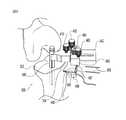
図1〜3は、例示的な、基準ピン10の配置をガイドするべく構成されたナビゲーション付き整形外科ガイド20を示しており、その上に大腿骨切削ガイド50が位置決めされて、膝置換外科手術における大腿骨コンポーネントを受けるための大腿骨2の切削をガイドする。ガイド20は、正面22、正面22の反対側の背面24、正面22から背面24まで延びる周囲の側壁26を有する本体21を含む。図示した例においては、整形外科ガイド20が、正面22と背面24の間の、側壁26の外辺部の内側の本体21内に埋め込まれた電磁コイル28の形式で追跡エレメントを含んでいる。コイル28は、コイル28から本体21の外へ延び、外科ナビゲーション・システムへ接続される、外科ナビゲーション・システムとコイル28の間において信号を伝達するためのリード30を含む。コイル28は、それが電磁界内に置かれると、電荷を発生し、それが外科ナビゲーション・システムへ伝達され、その結果、コイル28の、したがって整形外科ガイド20の3次元ポジションならびに向きを外科ナビゲーションの座標系に関係づけることが可能になる。たとえば、外科ナビゲーション・システムが複数のセンサを既知の場所に含み、それらがコイル28からの信号を受信し、その情報をコンピュータへ与えるようにすることができる。それによりコンピュータは、外科ナビゲーションの座標系内におけるコイルの3次元ポジションの三角測量を行うことができる。続いて外科ナビゲーション・システムは、コイル28のポジションならびに向きを検出し、かつコイル28と整形外科ガイド20の間における既知の関係から整形外科ガイド20のポジションならびに向きを解明することによって、整形外科ガイド20のポジションならびに向きを決定することができる。 1-3 show an exemplary orthopedic
図示の例は、能動的電磁追跡エレメントを示しているが、追跡エレメントは、電磁気的に、音響的に、イメージングによって、あるいはそのほかの適切な検出手段によって検出することができる。さらに、追跡エレメントは、能動的であってもよく、あるいは受動的であってもよい。能動的追跡エレメントの例としては、特に電磁気システムにおける電磁界エミッタ(たとえば、例示のコイル28)、イメージング・システムにおける発光ダイオード、および音響システムにおける超音波エミッタが挙げられる。受動的追跡エレメントの例としては、反射面を伴うエレメントを挙げることができる。たとえば、反射球体もしくはディスクを整形外科ガイドへ取り付け、イメージング・システムによって検出してもよい。 Although the illustrated example shows an active electromagnetic tracking element, the tracking element can be detected electromagnetically, acoustically, by imaging, or by other suitable detection means. Furthermore, the tracking element may be active or passive. Examples of active tracking elements include electromagnetic field emitters (eg, exemplary coil 28), particularly in electromagnetic systems, light emitting diodes in imaging systems, and ultrasonic emitters in acoustic systems. An example of a passive tracking element can include an element with a reflective surface. For example, a reflective sphere or disk may be attached to the orthopedic guide and detected by the imaging system.
整形外科ガイド20は、骨の上または中に、その後に用いられるコンポーネントをガイドする基準を設定するための手段を含む。例示の整形外科ガイド20においては、ホール32、34、36が、正面22から背面24まで整形外科ガイド20内を延びている。これらのホールは、ピン10、スクリュー、またはそのほかの基準の配置をガイドすることができる。たとえば、ホール32、34、36の1つもしくは複数に沿ってドリル・ビットをガイドし、下にある骨2内にホール40(図2)を形成することができる。続いて骨2内のそのホールの中に基準ピン10を挿入することができる。それに代えてセルフ‐ドリリング・ピンを使用してもよい。またそれに代えて基準ピン10を省略し、骨2内に形成されたホール40自体を基準として機能させることもできる。さらにそれに代えて、整形外科ガイド20が、ノッチ、スロット、ガイド面、あるいはそのほかの特徴を含み、骨2内におけるノッチ、スロット、またはそのほかの基準の形成をガイドするようにしてもよい。さらにまたそれに代えて、整形外科ガイド20が、スロット、ノッチ、ガイド面、あるいはそのほかの特徴を含み、骨2内またはその上におけるバー、レール、またはそのほかの基準の配置をガイドするようにしてもよい。 The
骨2上に基準が配置された後は、当該基準を外科手術コンポーネントの参照として、正しいポジションに当該外科手術コンポーネントを配置することができる。たとえば図3においては、大腿骨切削ガイド50が、整形外科ガイド20を使用してセットされた基準ピン10を受けるためのホール52、54、および56を含んでいる。それに代えて、外科手術コンポーネントが、整形外科ガイド20を使用して形成されたホール40と係合するための突出部、あるいは整形外科ガイド20を使用して配置された別のタイプの基準と係合するためのそのほかの特徴を含むこともできる。大腿骨切削ガイド50は、正面60、背面62、および正面60から背面62まで延びる周囲の側壁63を有する本体58を含む。基準受けホール52、54、56は、正面60から背面62まで延びている。複数のスロット64、66、68、70、72が、正面60から背面62へ切削ガイド50を通って形成されており、大腿骨膝インプラントを受けるべく大腿骨2の端部を成形するカッターをガイドする。たとえば、後部切削スロット70は、鋸刃をガイドして大腿骨2上に後部小関節面を切削することができる。後部面取り切削スロット68は、鋸刃をガイドして大腿骨2上に後部面取り小関節面を切削することができる。前部切削スロット64は、鋸刃をガイドして大腿骨2上に前部小関節面を切削することができる。前部面取り切削スロット66は、鋸刃をガイドして大腿骨2上に前部面取り小関節面を切削することができる。滑車窩切削スロット72は、鋸刃をガイドして大腿骨2上に滑車窩のベースを切削することができる。これらに加えて、ドリル・ガイド・ホール74は、ドリル・ビットをガイドして大腿骨インプラントの固定ポストを受けるためのポスト・ホールを大腿骨内に形成することができる。固定ポスト76は、鋸による切削およびドリルによる穿孔が行われる間、切削ガイド50を骨2上の正しい位置に保持するための、追加のピン、スクリュー、もしくはそのほかの留め具を受けるべく配置される。 After the fiducial is placed on the
図1に例示したガイド20においては、ホール32、34、36が、広範なサイズで提供される切削ガイド50内に形成されたホールに対応する。整形外科ガイド20内の中心ホール32は、切削ガイド50内の中心ホール52に対応しており、すべてのサイズの切削ガイド50について共通である。基準ピン10を受けるための追加のホール54、56は、切削ガイド50のサイズによって場所が異なることがある。したがって、整形外科ガイド20は、対応する追加の整形外科ガイド・ホール34、36のための複数の場所を含んでいる。追加の整形外科ガイド・ホール34、36には、使用が予定されている切削ガイド50のサイズを識別するためのラベル付けを行ってもよい。その後、基準ピン10が、相応じてラベルの付けられた整形外科ガイド・ホール34、36を使用して配置される。2本のピン10は、切削ガイド50を明確に設置する上で充分である。 In the
次に整形外科ガイド20の使用を、膝関節置換外科手術の間の大腿骨2の遠位端の置換手順における一例の大腿骨切削ガイド50の外科手術コンポーネントとの関係から説明する。施術者は、手術前に、手術中に望まれる大腿骨インプラントのサイズならびに場所を決定する。たとえば、X線イメージ、CTデータ、MRIデータ、もしくはそのほかの患者データをディジタル化して、患者の解剖学的構造のコンピュータ・モデルを形成し、コンピュータ・スクリーン上において利用可能な膝インプラントのモデルとの重合を行うことができる。施術者は、続いて適切なインプラントのサイズを選び、仮想的にそれをコンピュータ・モデル内の所望の場所へ誘導する。この位置決め情報が、その後、外科ナビゲーション・システムによって使用され、選択した大腿骨切削ガイド50を適正に位置決めする適切なポジションに整形外科ガイド20内の中心共通ホール32を位置決めするべく施術者をガイドすることができる。たとえば施術者は、この分野に周知のように従来的な方法で遠位切削表面4を形成することができる。次にナビゲーション付き整形外科ガイド20を遠位切削表面4上に配置し、中心ホール32が要求されたポジション内にあることを外科ナビゲーション・システムが示すまで、それを操作する。続いて、中心ホール32を介して大腿骨2内への穿孔を行い、穿孔したホール40内へ基準ピン10を押し込むことによって基準ピン10を挿入することができる。次に整形外科ガイド20を、特定の前後(A/P)および内外側(M/L)ポジション内において固定するが、このときは、予定されているインプラントのサイズに対応する別のホール34、36が適切な回転ポジションとなったことを外科ナビゲーション・システムが示すまで中心ホール32内の基準ピン10周りにそれを回転することができる。その後、適切なホール34、36を介して大腿骨2内への穿孔を行い、穿孔したホール40内へ基準ピン10を押し込むことによって基準ピン10を挿入することができる。この時点において、整形外科ガイド20を基準ピン10から持ち上げることによってそれを取り外すことができる。この基準ピン10の上から適切な大腿骨切削ガイド50をスライドさせることによって大腿骨2の遠位切削表面4上に切削ガイド50を位置決めすることができる。切削ガイドは、1ないしは複数の固定ポスト76を介してピン、スクリュー、もしくはそのほかの留め具を大腿骨2内へ挿入することによって骨に対して固定することができる。切削ガイド50内のスロット64、66、68、70、72、およびホール74を使用して鋸刃およびドリルをガイドし、特定サイズのインプラントを所望のA/P、M/L、および回転ポジションにおいて支持するべく大腿骨2の準備を行うことができる。 The use of the
上記に代えて整形外科ガイド20自体を、その後に用いられるコンポーネントをガイドするための基準として機能させてもよい。たとえば、整形外科ガイド20がホール、スロット、平面、および/またはそのほかの、その後に用いられるコンポーネントを直接的に係合し、かつ外科手術の座標系に関してガイドするための特徴を含むことができる。たとえば、切削ガイド50のスロット64、66、68、70、72、およびホール74を、ナビゲーション付きガイド20内に直接形成してもよい。しかしながら、切削ガイド50のすべての特徴を伴うナビゲーション付きガイド20は、切削ガイド50より高価なものとなり、かつ/またはより精密なものとなる。通常、切削ガイド50が各種のサイズで提供されることから、前述したように基準を設定するための別体のナビゲーション付きガイド20を提供する方が、よりコストが低く、かつ/または必要なメンテナンスがより少なくて済む。さらにまた、別体のナビゲーション付きガイドは、現存するナビゲーション付きでない切削ガイド50を使用しつつ、外科ナビゲーション・テクノロジの恩典を提供するべく使用することができる。これは、必要とされる新しい器械の数を低減することによって、ナビゲーション付きでない手順からナビゲーション付きの手順への移行のコストを有意に抑える。 Instead of the above, the
図4は、図1のナビゲーション付き整形外科ガイドに関する代替構成を示している。図4の整形外科ガイド120の幅は、図1の整形外科ガイド20の約半分である。より小さいこの整形外科ガイド120は、侵入が最小限の、すなわち切開サイズが縮小される外科手術手順における使用に良好に適する。ガイド120は、本体121および、外科ナビゲーション・システムによるガイド120のポジションならびに向きの追跡を可能にする電磁コイル128の形式の追跡エレメントを含んでいる。ハンドル125がガイド120から延びており、切開部位へのガイドの挿入を容易にする。侵入が最小限の外科手術手順においては、ガイド本体121が柔らかい組織によって概ねカバーされるように、ガイド120のエッジ123を切開部位の縁の下へ滑らせる必要が生じることがある。ハンドル125は、切開部位から突出する把持表面を提供する。ガイド本体121は、中心ホール132ならびに追加の基準ガイド・ホールの第1および第2のセット134、136を含む。追加の基準ガイド・ホール134、136は、それぞれのホールに関連付けされた対応する切削ガイド50を示すべくラベル付けされている。サイズが半分の器械上において基準ガイド・ホール134、136をより良好に適応させるために、代替オフセット中心ホール133が備えられている。この代替オフセット中心ホール133は、第2の基準ガイド・ホールのセット136が第1の基準ガイド・ホールのセット134からオフセットされ、かつオーバーラップしないように第2の基準ガイド・ホールのセット136と関連付けされている。視覚的キュー、たとえばエッチングによるライン137、139を備えて、対応する中心ホール132、133と追加の基準ガイド・ホール134、136を関連させることもできる。 FIG. 4 shows an alternative arrangement for the orthopedic guide with navigation of FIG. The width of the
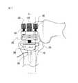
図5〜7は、図1のナビゲーション付き整形外科ガイドの例示的な代替構成を示しており、さらにこれは、調整メカニズムを含んでいる。ガイド200は、ベース部材202、基準を設定するためのガイド部材280、およびベース部材202とガイド部材280を接続する接続リンク240を含む。ベース部材202は、外科ナビゲーション座標系内においてガイド200を固定する。たとえば、ベース部材202は、外科手術部位に隣接する骨に固定することができる。例示した幅の狭い細長い形状のベース部材202は、侵入が最小限の外科手術テクニックにおいて使用されるような狭い切開部位に適合することができる。例示したベース部材202は、骨に関してベース部材202を固定する固定部材を受けるための固定ホール204を含む。固定ホール204は図示のように1つの辺に関して角度を付けることができ、固定部材が角度をもって小さい切開部位を通り、かつ/または内側または外側にオフセットされた切開部位を通って挿入されることを可能にする。接続リンク240は、ベース部材202に関してガイド部材280が調整されること、およびガイド部材280が骨に関して所望の向きで固定されることを可能にする。この可調性は、接続リンク240をベース部材202ならびにガイド部材280へ接続する調整メカニズムによって提供される。 5-7 show an exemplary alternative configuration of the navigational orthopedic guide of FIG. 1, which further includes an adjustment mechanism. The
接続リンクは、ベース部材202から延びている立ち上がりブロック206を介してベース部材202へ接続される。接続リンク・ボルト208が、サドル・ワッシャ210を通り、立ち上がりブロック206を貫通して延び、第1のロッキング・ノブ212と螺合する。接続リンク・ボルト208は、横行ボア216を有するヘッド214を含む。接続リンク240は、横行ボア216によって受けられる円柱シャフト242を有し、ボア216ならびに軸217に沿って移動し、かつそれを中心として回転することができる。第1のロッキング・ノブ212が接続リンク・ボルト208のねじ溝218上に締め付けられると、接続リンク・ボルト208がサドル・ワッシャ210ならびに立ち上がりブロック206を通って引き込まれる。接続リンク240の円柱シャフト242が引き込まれて、サドル・ワッシャ210内のノッチ220と隣接する。第1のロッキング・ノブの締め付けは、サドル・ワッシャ210に、ベース部材202と相対的に接続リンク240をロックさせ、ベース部材202に関する接続リンクの移動および回転を防止する。接続リンク・ボルトのヘッド214は、円柱シャフト242が横行ボア216から脱落したときに、意図せずして接続リンク・ボルト208がサドル・ワッシャ210ならびに立ち上がりブロック206を通過してしまうことのないように、半径方向に径を大きくして、たとえばショルダ222を形成することができる。接続リンク・ボルト208は、サドル・ワッシャ210ならびに立ち上がりブロック206内の非円形ボア226、228に対応する非円形シャフト部分224を含み、ベース部材202に関する接続リンク・ボルト208の回転を防止することができる。接続リンク・ボルト208の回転を抑えることによって、接続リンク240とベース部材202の間における唯一の相対的な動きは、横行ボアの軸217に沿った平行移動およびそれを中心とする回転となる。さらに、接続リンク・ボルト208の束縛は、第1のロッキング・ノブ212の締め付けを容易にする。 The connection link is connected to the
立ち上がりブロック206は、スリット230を含んでおり、それが立ち上がりブロックを、間が空けられた2つの片持ち部分232、234に分割する。これらの部分232、234は、スプリングとして作用し、スプリングがない場合に比べて、より広い歪力調整範囲を調整メカニズム内に提供する。このスリット230があることによって、ガイド部材280の重量が作用するときにおいても第1のロッキング・ノブ212を調整して横行ボア216内の所望のポジションにおいて円柱シャフト242を保持するに充分な歪力を容易に得ることができ、しかもユーザは、手で押すことによって横行ボア216内の円柱シャフト242を移動させることができる。その後、第1のロッキング・ノブ212を締め付けて、円柱シャフト242を最終的な所望のポジションにロックすることができる。 The rising
接続リンク240は、接続リンク240から延びているタブ244を介してガイド部材280と接続される。タブ244は、横行ボア軸217に関して角度が付けられたボア軸248を有するボア246を含む。ボア軸217と248の間における角度は、ベース部材202に関するガイド部材280の第2の回転調整を可能にする。ガイド部材280は、間隔が空けられた第1および第2のアーム284、286を有するヨーク282を含む。各アーム284、286は、細長いスロット288を含み、それによってベース部材202に関するガイド部材280の第2の平行移動調整が可能になる。タブ244は、アーム284と286の間において、スライドし、かつ枢動する関係で受けられる。ガイド部材ボルト290が、一方のアーム284を通り、タブ244内のボア246を通り、さらに他方のアーム286を通って第2のロッキング・ノブ292と螺合する。この構成は、ガイド部材280がタブのボア軸248周りに回転すること、および細長いスロット288に沿って平行移動することを抑える。ガイド部材ボルト290は、半径方向に広がったヘッド294を有し、それが一方のヨーク・アーム284と接して、ボルトがスロット288を通り抜けることを防止する。第2のロッキング・ノブ292がガイド部材ボルト290上のねじ溝296上に締め付けられると、ヨーク・アーム284、286が互いにたわみ、接続リンク240のタブ244を把持する。アーム284、286のスプリング作用によってタブ244の把持歪力の範囲が広がり、その結果、ガイド部材280の重量が作用するときにおいても第2のロッキング・ノブ292を調整してヨーク282内の所望のポジションにおいてタブ244を保持するに充分な歪力を容易に得ることができ、しかもユーザは、手で押すことによってヨーク282内のタブ244を回転させることができる。その後、第2のロッキング・ノブ292を締め付けてタブ244を、したがってガイド部材280を最終的な所望のポジションにロックすることができる。1ないしは複数のオプションのロック・ワッシャ250を、タブ244とヨーク282の間に備えてもよい。ワッシャには、歯252を備えて、ヨーク282とタブ244の間の把持を増加することができる。さらに、ガイド部材ボルト・ヘッド294に、スロット288に隣接する対応する凹部(図示せず)内に受けられる非円形プロファイルを持たせれば、第2のロッキング・ノブ292を締め付けるときにボルト290が回転することを防止できる。たとえばボルト・ヘッド294が、スロット288の周囲を囲む平らな側面の埋頭孔(図示せず)内に嵌り込む平らな側面295を有するようにしてもよい。 The
ガイド部材280は、外科ナビゲーション・システムの座標系内において基準を設定するための手段を含む。図5に例示した整形外科ガイドにおいては、ガイド部材280が、基準を設定するピンをガイドするためのガイド・ホール298を含んでいる。ガイド部材280は、電磁コイル300等の追跡エレメントを含み、外科ナビゲーション・システムによるガイド部材280のポジションならびに向きの追跡を可能にする。
使用時は、ベース部材202をシステムに既知の物体へマウントすることによって、それが外科ナビゲーション座標系内に固定される。たとえばベース部材202を、図6に示されているとおりに大腿骨299上にマウントすることができる。例示のベース部材202の細長い形状によって、それを小さい切開部位内へ差し込むことが可能になる。たとえば、膝関節に隣接する狭い内側または外側の切開部位を介してベース部材202を挿入することができる。さらに、図示のとおり固定ホール204に角度を持たせることができ、その種の内側または外側の切開部位を介して固定部材を挿入することが可能になる。第1および第2のロッキング・ノブ212、292は、ベース部材202に関してガイド部材280が移動できるように緩められる。図6に示されているように大腿骨299上にベース部材202が配置されると、第1のロッキング・ノブ212が内外側ポジションならびにガイド部材280の屈曲角度をロックする。第2のロッキング・ノブ292は、ガイド部材280の内反‐外反ポジションおよび切除深度をロックする。このメカニズムは、ガイド部材280が所望のポジションへ配置されたことを外科ナビゲーション・システムが示すまで操作される。その後、第1および第2のロッキング・ノブ212、292を締め付けて、ベース部材202に関する適切な位置にガイド部材280をロックする。このガイド部材280は、その後に用いられる外科手術コンポーネントをガイドするための基準の設定に使用することができる。たとえば、ガイド・ホール298を介して大腿骨299内へピン302を挿入することができる。その後は、ナビゲーション付き整形外科ガイド200を取り外すことができる。 In use, it is secured within the surgical navigation coordinate system by mounting the
図7は、ピン302上にマウントされた遠位大腿骨切削ブロック304を例示している。遠位大腿骨切削ブロック304は、ピン302を受けるためのホール306、308、310、および骨の上に表面を形成するカッターをガイドするカッター・ガイド312を含む。ホール306、308、310は、複数行のホールとして提供することができる。各行は、異なるレベルの切除を提供することができる。たとえば、ホール308の1つの行を、あらかじめ決定された基準切除レベルに対応させることができる。追加の行306、310は、施術者の選択もしくは骨の状態から必要とされる場合に骨の切削を増減するために備えることができる。各行に、使用されるピン302の数より多くのホールが備えられていることから、遠位大腿骨切削ブロック304をピン302から持ち上げて外し、同じ行内の隣接するホール上へ再び配置することによって、その前後ポジションを調整することができる。所望の切除レベルならびに前後ポジションにおいて切削ブロック304が位置決めされている状態で、ホール306、308、310のいくつかを介して追加の固定部材を挿入すれば、カッターがガイドされて骨299を切削する間、切削ブロック304を適正な位置に保持することができる。 FIG. 7 illustrates a distal
図5〜7の調整可能なナビゲーション付き整形外科ガイド200は、大腿骨299の遠位部分に基準を位置決めし、遠位大腿骨切削ブロック304を位置決めするべく構成されている。しかしながら、この調整可能なガイドは、このほかの、大腿骨仕上げガイドおよび/または頸骨切削ガイド等の切削ガイドを含む外科手術コンポーネントのための基準の設定にも使用することができる。また、図1〜3および4のナビゲーション付き整形外科ガイドの場合と同様に、図5〜7のガイド自体を基準として機能させ、その後に用いられる外科手術コンポーネントを直接ガイドすることもできる。 The adjustable navigation
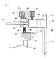
図8〜11は、図1の整形外科ガイドに関する別の例の代替構成を図示しており、さらにこれには調整メカニズムが含まれている。ガイド400は、ベース部材402、ガイド部材480、およびベース部材402とガイド部材480を調整可能に接続するための接続リンケージ440を含む。ベース部材402は、接続リンケージ440を受けるための受けブロック404、および外科ナビゲーション座標系内においてガイドを固定するためのアンカー部分406を含む。例示のアンカー部分406は、骨の中に打ち込むことのできる主マウンティング・ポスト408を含む。この主マウンティング・ポスト408は、骨に関するベース部材402の回転を阻止するフィン410を含むことができる。ベース部材402の回転を阻止するために補助マウンティング・ポスト411を含めてもよい。補助マウンティング・ポスト411を半径方向に主マウンティング・ポスト408から離隔して、より大きな回転に抗するモーメント・アームを作り出すことができる。ベース部材402は、骨から取り外すときにベース部材402を把持するための手段を含むことができる。例示のアンカー部分406は、ベース部材402の上に延びており、ピン抜き、スラップ・ハンマー、および/またはそのほかのベース部材402を抜き取るための適切な器械が係合することのできる環状グルーブ412を含んでいる。 8-11 illustrate another example alternative configuration for the orthopedic guide of FIG. 1, which further includes an adjustment mechanism. The
接続リンケージ440は、ベース部材402に関するガイド部材480の調整を可能にし、ガイド部材480を骨に関して望ましい向きに固定することを可能にする。この可調性は、接続リンケージ440をベース部材402ならびにガイド部材480へ接続する調整メカニズムによって提供される。 The
接続リンケージ440は、回転サポート442によってベース部材402と接続される。図示の例においては、回転サポート442が、上側表面443、下側表面445、および一端から突出しているトラニオン446を有するプレート状の本体444を含んでいる。トラニオン446は、受けブロック404内に形成されたボア414内に受けられ、ボア414の軸416周りに回転する。セット・スクリュー418が受けブロック404内に螺合され、回転サポート442を適正な位置でロックする。トラニオン446は、環状グルーブ448を含み、セット・スクリュー418の先端420を受けることができる。セット・スクリュー418とグルーブ448の係合が緩い状態においては、ボア軸416周りの回転サポート442の回転が許されるが、ボア軸416に沿った平行移動は妨げられる。セット・スクリュー418の締め付けは、回転サポート442を、その回転されたポジションにおいてロックする。 The
回転サポート442の反対側の端部には、調整スクリュー・ハウジング450が支持されている。ハウジング450は、対向する支点456によって画定される横行開口454を伴う本体452を含む。回転サポート442は、その上側および下側の表面443、445が対向する支点456の頂点458と密に嵌り合う関係で開口454内に受けられる。支点456は、ハウジング450を回転サポート442に関してロックすることができる。ペアの角度調整スクリュー460が調整スクリュー・ハウジング450内に螺合されており、スクリュー460がそれを通り、開口454と連通して回転サポート442の上側表面433と係合することができるようになっている。スクリュー460は、支点の頂点458を挟んで互いが反対側となるように調整スクリュー・ハウジング450に配置されている。角度調整スクリュー460の一方を緩め、他方を締めることによって、調整スクリュー・ハウジング450が支点の頂点458上を枢動し、回転サポート442に関するハウジング450の角度を調整することが可能になる。 An
接続リンケージ440は、ハウジング450へ接続されるガイド部材480の部分によってガイド部材480と接続される。図示の例においては、ねじ付きロッド482がガイド部材480から延びており、ハウジング、対向する支点456の頂点458、および回転サポート442に形成された細長いスロット462を貫通して調整ナット464と螺合する。スプリング466が、ガイド部材480とハウジング450の間に介挿されており、それらを引き離すべく付勢している。調整ナット464を締め込むと、ねじ付きロッド482がハウジング450内に引き込まれ、それによってガイド部材480がハウジング450に向かって移動し、スプリング466を圧縮する。調整ナット464を緩めると、ガイド部材480がハウジング450から離される。 The
ガイド部材480は、外科ナビゲーション・システムの座標系内において基準を設定するための手段を含む。図8に例示した整形外科ガイドにおいては、ガイド部材480が正面484および背面486を有するガイド部材本体483を含んでいる。ピンをガイドして基準を設定するためのガイド・ホール487が正面484から背面486まで延びている。ガイド部材480は、電磁コイル488の形式で追跡エレメントを含んでおり、外科ナビゲーション・システムが、ガイド部材480のポジションならびに向きを追跡することができる。
ガイド部材480は、オプションとして、その後に用いられる外科手術コンポーネントを直接ガイドするための基準面を含むことができる。図8〜11に例示した整形外科ガイドは、細長いカッター・ガイド・スロット490の形式の基準表面を含み、それが正面484から背面486まで延び、その後に用いられる外科手術コンポーネントを直接ガイドする。オプションの直接ガイド基準表面が備えられる場合には、ホール487が固定部材を受け、その後に用いられる外科手術コンポーネントをガイド部材480が直接ガイドする間、ガイド部材480を保持するようにすることができる。通常、広範なサイズが用意されなければならない大腿骨切削ガイドと異なり、しばしば広範多様な頸骨サイズの切削に単一の頸骨切削ガイドを使用することが可能である。したがって、図示のように頸骨への使用のために構成された、単一の直接ガイド整形外科ガイドを提供すると有利なことがある。しかしながら、図8〜11の整形外科ガイドを、頸骨切削ガイド、大腿骨切削ガイド、インプラント、および/またはそのほかの外科手術コンポーネント等の別体の外科手術コンポーネントのための基準の設定に使用することもできる。またこれを、現存する頸骨切削ガイドのための基準の設定に使用し、現存するナビゲーション付きでないコンポーネントに外科ナビゲーション・テクノロジの恩典を提供することもできる。
使用においては、図9および10に示されているように、マウンティング・ポスト408を骨の中に挿入し、骨に隣接してガイド400を固定する。頸骨500上において使用する場合には、マウンティング・ポスト408を近位頸骨表面502を介して挿入し、前頸骨皮質504と隣接させてガイド部材480を位置決めする。両方の角度調整スクリュー460を緩めれば、前頸骨皮質504に関して望ましいポジションまでハウジング450およびガイド部材480を回転サポート442に沿ってスライドさせることができる。セット・スクリュー418を緩めた状態では、回転サポート442、ハウジング450およびガイド部材480を回転して、ガイド部材480の内反‐外反の向きを調整することができる。角度調整スクリュー460を差動的に締め込むことによって、図11にもっともよく示されているが、支点の頂点458周りに、回転サポート442に関するハウジング450およびガイド部材480の角度設定を行うことができる。この角度調整は、ガイド部材480の後部傾斜の向きを調整する。最後に、調整ナット464を締め込むか、緩めることによって、ガイド部材480の高さを変更し、ガイド部材480の切除深度ポジションを設定することができる。これらの調整は、外科ナビゲーション・システムを使用してガイド部材480を追跡する間に行うことができる。ガイド部材480が所望のポジションにあることを外科ナビゲーション・システムが示したとき、調整スクリューを締め込み、そのポジションをロックすることができる。この状態でガイド部材480を使用し、ガイド部材480のホール487を介して基準ピン506を前頸骨皮質504内へ挿入することなどによって頸骨500上に基準を設定することができる。その後ガイド400を取り外し、その後に用いる外科手術コンポーネントを基準ピン506へ係合させることができる。たとえば、近位頸骨表面502を切除するカッターをガイドするための切削ブロックを基準ピン506へ係合させることができる。それに代えて、ガイド・スロット490を用いる場合のように、ガイド部材480が基準を直接設定し、その後に用いる外科手術コンポーネントをガイドしてもよい。たとえば、カッターをガイド・スロット490内へ挿入して近位頸骨表面502を切除するべくカッターをガイドすることができる。 In use, as shown in FIGS. 9 and 10, mounting
図8〜11に例示した整形外科ガイド400は、膝置換外科手術手順の間にカッターを直接ガイドして近位頸骨上に切削表面を形成するべく構成されている。しかしながらこの整形外科ガイド400は、そのほかの外科手術コンポーネントおよび/またはそのほかの外科手術部位のための直接ガイドもしくは基準の設定にも使用することができる。たとえば、整形外科ガイド400を使用し、器械またはインプラントを膝関節の頸骨または大腿骨、股関節の大腿骨または骨盤に関する所望のポジションへ、かつ/またはそのほかのコンポーネントをそのほかの部位へ、直接ガイドし、あるいはガイドするための基準を設定することができる。 The
ナビゲーション付き整形外科ガイドおよびその使用の例を説明し、詳細に例示してきたが、それらが説明ならびに例示として意図されたものであり、限定として解釈されるべきではないことが理解される必要がある。本発明は、膝置換外科手術に関連する特定の部位におけるピンの設定またはカッターのガイドを行う整形外科ガイドを用いて例示されている。しかしながらこの整形外科ガイドは、患者の身体内のこのほかの部位において、このほかのタイプの基準を配置するために、このほかのタイプの外科手術コンポーネントを伴う使用に関して構成することができる。したがって、当業者にとってはこの整形外科ガイドの変形ならびにそれに関する修正が明らかなものとなるであろうが、特許請求の範囲は、それらの修正ならびに等価物のすべてを保護するべく意図されている。 Although examples of navigational orthopedic guides and their use have been described and illustrated in detail, it should be understood that they are intended to be illustrative and exemplary and should not be construed as limiting . The present invention is illustrated using an orthopedic guide that sets pins or guides a cutter at a specific site associated with knee replacement surgery. However, the orthopedic guide can be configured for use with other types of surgical components to place other types of fiducials at other sites within the patient's body. Accordingly, while variations of this orthopedic guide and modifications related thereto will be apparent to those skilled in the art, the claims are intended to protect all such modifications and equivalents.
2 骨/大腿骨
4 遠位切削表面
10 基準ピン
20 ナビゲーション付き整形外科ガイド
21 本体
32,34,36,40 ホール
50 切削ガイド/大腿骨切削ガイド
52,54,56 ホール
64,66,68,70,72 スロット
76 固定ポスト
120 整形外科ガイド
134 第1の基準ガイド・ホールのセット
136 第2の基準ガイド・ホールのセット
200 ナビゲーション付き整形外科ガイド
202 ベース部材
204 固定ホール
206 立ち上がりブロック
208 接続リンク・ボルト
210 サドル・ワッシャ
212 第1のロッキング・ノブ
214 ヘッド
216 横行ボア
217 横行ボア軸/軸
218 ねじ溝
220 ノッチ
222 ショルダ
240 接続リンク
242 円柱シャフト
248 ボア軸
280 ガイド部材
282 ヨーク
284 第1のアーム
286 第2のアーム
299 大腿骨
302 ピン
304 遠位大腿骨切削ブロック
306,308,310 ホール
402 ベース部材
408 主マウンティング・ポスト
411 補助マウンティング・ポスト
440 接続リンケージ
444 本体
446 トラニオン
450 調整スクリュー・ハウジング
452 本体
483 ガイド部材本体
500 頸骨
502 近位頸骨表面
504 前頸骨皮質
506 基準ピン2 bone /
Claims (41)
Translated fromJapanese前記外科手術部位に関する所望のポジションに前記整形外科ガイドを位置決めするべく前記外科ナビゲーション・システムによって追跡されるための手段と、
前記外科手術部位に関する所望のポジションにおいて基準を、その後に用いられる外科手術コンポーネントの配置をガイドするべく前記その後に用いられる外科手術コンポーネントによって前記基準が係合されることが可能となるように設定するための手段とを、
備えるナビゲーション付き整形外科ガイド。An orthopedic guide with navigation for setting a reference for a surgical site for use with a surgical navigation system during an orthopedic surgical procedure, the reference guiding the placement of surgical components used thereafter So that it can be engaged by a subsequent surgical component, wherein
Means for being tracked by the surgical navigation system to position the orthopedic guide at a desired position with respect to the surgical site;
A reference is set at a desired position with respect to the surgical site such that the reference can be engaged by the subsequently used surgical component to guide the placement of subsequently used surgical components. Means for
An orthopedic guide with navigation.
外科手術手順の間における物体のポジションを追跡するための手段を含む外科ナビゲーション・システムと、
ナビゲーション付き整形外科ガイドであって、前記外科手術部位に関する所望のポジションに前記整形外科ガイドのポジションをガイドするべく前記外科ナビゲーション・システムによって追跡されるための手段を含み、かつ前記外科手術部位に関する所望のポジションにおいて基準を設定するための手段を含む整形外科ガイドと、
外科手術コンポーネントであって、前記外科手術部位に関する所望のポジションに前記外科手術コンポーネントを配置するべく前記整形外科ガイドによって位置決めされた基準と係合するための手段を含む外科手術コンポーネントと、
を備える外科手術システム。A surgical system for use during an orthopedic surgical procedure at a surgical site in a patient's body, comprising:
A surgical navigation system including means for tracking the position of an object during a surgical procedure;
An orthopedic guide with navigation, comprising means for being tracked by the surgical navigation system to guide the position of the orthopedic guide to a desired position with respect to the surgical site, and desired with respect to the surgical site An orthopedic guide including means for setting a reference in a position of
A surgical component comprising means for engaging a reference positioned by the orthopedic guide to place the surgical component in a desired position with respect to the surgical site;
A surgical system comprising:
外科ナビゲーション・システムを作動させて整形外科ガイドのポジションを追跡し、
前記外科ナビゲーション・システムによって示されるとおりの所望のポジション内において前記外科手術部位に関して前記整形外科ガイドを位置決めし、
前記整形外科ガイドを用いて前記外科手術部位に関して基準を設定し、
前記外科手術部位に関する所望のポジションにおいて外科手術コンポーネントを位置決めするべく前記基準と前記外科手術コンポーネントを係合させる整形外科手術手順を行う方法。A method for performing an orthopedic surgical procedure at a surgical site in a patient's body, comprising:
Activate the surgical navigation system to track the position of the orthopedic guide,
Positioning the orthopedic guide with respect to the surgical site within a desired position as indicated by the surgical navigation system;
Using the orthopedic guide to set a standard for the surgical site;
A method of performing an orthopedic surgical procedure that engages the reference and the surgical component to position the surgical component at a desired position with respect to the surgical site.
前記外科ナビゲーション・システムによって示されるとおりの所望の場所に前記整形外科ガイドの第1のホールを位置決めすることと、
前記第1のホールを介して前記骨に第1のピンを挿入することと、
前記外科ナビゲーション・システムによって示されるとおりの所望の場所に第2のホールが位置決めされるまで、前記第1のピン周りに前記整形外科ガイドを枢動することと、
前記第2のホールを介して前記骨に第2のピンを挿入すること、
を含む請求項29に記載の方法。The orthopedic guide includes a plurality of holes for placing pins in the bone at the surgical site, and setting the reference includes
Positioning the first hole of the orthopedic guide at a desired location as indicated by the surgical navigation system;
Inserting a first pin into the bone through the first hole;
Pivoting the orthopedic guide around the first pin until a second hole is positioned at a desired location as indicated by the surgical navigation system;
Inserting a second pin into the bone through the second hole;
30. The method of claim 29, comprising:
この方法は、前記切削ガイドを用いてカッターをガイドし、整形外科インプラントを受けるべく骨を成形することを含む請求項31に記載の方法。The surgical component includes a cutting guide for guiding a cutter for cutting bone to receive an implant;
32. The method of claim 31, wherein the method includes guiding a cutter with the cutting guide and shaping bone to receive an orthopedic implant.
前記ベース部材を前記外科手術部位に隣接する骨に関して固定し、
前記外科ナビゲーション・システムによって示されるとおりの所望の基準ガイド部材ポジションへ、前記ベース部材に関して前記基準ガイド部材を調整する請求項27に記載の方法。And providing an orthopedic guide having a base member and a reference guide member adjustable with respect to the base member;
Fixing the base member with respect to the bone adjacent to the surgical site;
28. The method of claim 27, wherein the reference guide member is adjusted with respect to the base member to a desired reference guide member position as indicated by the surgical navigation system.
従来的なナビゲーション付きでない外科手術器械を用意し、
ナビゲーション付き整形外科ガイドを用意し、
前記外科ナビゲーション・システムを用いて、前記外科手術部位に関する所望の場所へ前記ナビゲーション付き整形外科ガイドをガイドし、
前記外科手術部位において骨に関して基準を設定し、
前記従来的なナビゲーション付きでない外科手術器械と前記基準を係合させ、
前記従来的なナビゲーション付きでない外科手術器械を用いて前記外科手術を完了する整形外科手術を行う方法。A method of performing orthopedic surgery at a surgical site on a patient's body under the control of a surgical navigation system comprising:
Prepare surgical instruments without conventional navigation,
Prepare an orthopedic guide with navigation,
Using the surgical navigation system to guide the navigation orthopedic guide to a desired location with respect to the surgical site;
Setting a standard for bone at the surgical site;
Engaging the reference with the conventional non-navigable surgical instrument;
A method of performing orthopedic surgery to complete the surgery using the conventional non-navigated surgical instrument.
Applications Claiming Priority (1)
| Application Number | Priority Date | Filing Date | Title |
|---|---|---|---|
| US10/795,830US20070282347A9 (en) | 2002-12-20 | 2004-03-08 | Navigated orthopaedic guide and method |
Publications (1)
| Publication Number | Publication Date |
|---|---|
| JP2005253970Atrue JP2005253970A (en) | 2005-09-22 |
Family
ID=34827598
Family Applications (1)
| Application Number | Title | Priority Date | Filing Date |
|---|---|---|---|
| JP2005063845APendingJP2005253970A (en) | 2004-03-08 | 2005-03-08 | Orthopedic guide with navigation, surgical operation system, method for performing orthopedic surgery procedure and method for performing orthopedic surgery |
Country Status (7)
| Country | Link |
|---|---|
| US (1) | US20070282347A9 (en) |
| EP (1) | EP1574172B1 (en) |
| JP (1) | JP2005253970A (en) |
| AT (1) | ATE376392T1 (en) |
| AU (1) | AU2005200969A1 (en) |
| CA (1) | CA2491824A1 (en) |
| DE (1) | DE602005002962T2 (en) |
Cited By (5)
| Publication number | Priority date | Publication date | Assignee | Title |
|---|---|---|---|---|
| US8565853B2 (en) | 2006-08-11 | 2013-10-22 | DePuy Synthes Products, LLC | Simulated bone or tissue manipulation |
| KR101362252B1 (en) | 2012-06-28 | 2014-02-14 | 서울대학교산학협력단 | Patient-specific registration guide and method using the same |
| JP2014171876A (en)* | 2013-03-05 | 2014-09-22 | Depuy (Ireland) | Polymer 4-IN-1 femoral cutting block |
| US10111673B2 (en) | 2013-03-05 | 2018-10-30 | Depuy Ireland Unlimited Company | Polymer 4-in-1 femoral cutting block including metallic protective bushings |
| US12076025B2 (en) | 2022-05-11 | 2024-09-03 | DePuy Synthes Products, Inc. | Polymer cutting block |
Families Citing this family (141)
| Publication number | Priority date | Publication date | Assignee | Title |
|---|---|---|---|---|
| WO2003086213A2 (en)* | 2002-04-05 | 2003-10-23 | Smith & Nephew, Inc. | Orthopaedic fixation method and device |
| WO2004112610A2 (en) | 2003-06-09 | 2004-12-29 | Vitruvian Orthopaedics, Llc | Surgical orientation device and method |
| US7559931B2 (en) | 2003-06-09 | 2009-07-14 | OrthAlign, Inc. | Surgical orientation system and method |
| US8114086B2 (en) | 2004-03-08 | 2012-02-14 | Zimmer Technology, Inc. | Navigated cut guide locator |
| US7993341B2 (en)* | 2004-03-08 | 2011-08-09 | Zimmer Technology, Inc. | Navigated orthopaedic guide and method |
| US7377924B2 (en)* | 2004-09-09 | 2008-05-27 | Howmedica Osteonics Corp. | Navigated drill guided resection block |
| DE602004019551D1 (en)* | 2004-12-08 | 2009-04-02 | Perception Raisonnement Action | Device for positioning a bone cutting guide |
| US20060200158A1 (en)* | 2005-01-29 | 2006-09-07 | Farling Toby N | Apparatuses and methods for arthroplastic surgery |
| US8055487B2 (en)* | 2005-02-22 | 2011-11-08 | Smith & Nephew, Inc. | Interactive orthopaedic biomechanics system |
| US20070005065A1 (en)* | 2005-06-17 | 2007-01-04 | Fernandez Dell Oca Alberto A | Aiming arm hole shaped to perform an incision through, and method to use that same |
| US7983777B2 (en)* | 2005-08-19 | 2011-07-19 | Mark Melton | System for biomedical implant creation and procurement |
| US20070118140A1 (en)* | 2005-10-18 | 2007-05-24 | Aesculap Ag & Co. Kg | Method and apparatus for navigating a cutting tool during orthopedic surgery using a localization system |
| US20070233138A1 (en)* | 2006-01-27 | 2007-10-04 | Zimmer Technology, Inc. | Apparatuses and methods for arthroplastic surgery |
| US20070179630A1 (en)* | 2006-02-02 | 2007-08-02 | Zimmer Technology, Inc. | Hip stem centralizer cap and method |
| US7828805B2 (en)* | 2006-02-02 | 2010-11-09 | Zimmer Technology, Inc. | Hip stem centralizer datum guide, and method |
| US20070233156A1 (en)* | 2006-02-16 | 2007-10-04 | Robert Metzger | Surgical instrument |
| US9345548B2 (en) | 2006-02-27 | 2016-05-24 | Biomet Manufacturing, Llc | Patient-specific pre-operative planning |
| US8092465B2 (en)* | 2006-06-09 | 2012-01-10 | Biomet Manufacturing Corp. | Patient specific knee alignment guide and associated method |
| US8608749B2 (en) | 2006-02-27 | 2013-12-17 | Biomet Manufacturing, Llc | Patient-specific acetabular guides and associated instruments |
| US9173661B2 (en) | 2006-02-27 | 2015-11-03 | Biomet Manufacturing, Llc | Patient specific alignment guide with cutting surface and laser indicator |
| US8603180B2 (en) | 2006-02-27 | 2013-12-10 | Biomet Manufacturing, Llc | Patient-specific acetabular alignment guides |
| US10278711B2 (en) | 2006-02-27 | 2019-05-07 | Biomet Manufacturing, Llc | Patient-specific femoral guide |
| US20150335438A1 (en) | 2006-02-27 | 2015-11-26 | Biomet Manufacturing, Llc. | Patient-specific augments |
| US8377066B2 (en) | 2006-02-27 | 2013-02-19 | Biomet Manufacturing Corp. | Patient-specific elbow guides and associated methods |
| US8568487B2 (en) | 2006-02-27 | 2013-10-29 | Biomet Manufacturing, Llc | Patient-specific hip joint devices |
| US8535387B2 (en) | 2006-02-27 | 2013-09-17 | Biomet Manufacturing, Llc | Patient-specific tools and implants |
| US9918740B2 (en) | 2006-02-27 | 2018-03-20 | Biomet Manufacturing, Llc | Backup surgical instrument system and method |
| US9113971B2 (en) | 2006-02-27 | 2015-08-25 | Biomet Manufacturing, Llc | Femoral acetabular impingement guide |
| US8608748B2 (en) | 2006-02-27 | 2013-12-17 | Biomet Manufacturing, Llc | Patient specific guides |
| US9289253B2 (en) | 2006-02-27 | 2016-03-22 | Biomet Manufacturing, Llc | Patient-specific shoulder guide |
| US8591516B2 (en) | 2006-02-27 | 2013-11-26 | Biomet Manufacturing, Llc | Patient-specific orthopedic instruments |
| US8407067B2 (en) | 2007-04-17 | 2013-03-26 | Biomet Manufacturing Corp. | Method and apparatus for manufacturing an implant |
| US9339278B2 (en) | 2006-02-27 | 2016-05-17 | Biomet Manufacturing, Llc | Patient-specific acetabular guides and associated instruments |
| US9907659B2 (en) | 2007-04-17 | 2018-03-06 | Biomet Manufacturing, Llc | Method and apparatus for manufacturing an implant |
| US7967868B2 (en) | 2007-04-17 | 2011-06-28 | Biomet Manufacturing Corp. | Patient-modified implant and associated method |
| US9795399B2 (en) | 2006-06-09 | 2017-10-24 | Biomet Manufacturing, Llc | Patient-specific knee alignment guide and associated method |
| US20080015602A1 (en)* | 2006-06-22 | 2008-01-17 | Howmedica Osteonics Corp. | Cutting block for bone resection |
| US20080015708A1 (en)* | 2006-07-13 | 2008-01-17 | Zimmer Technology, Inc. | Hip stem centralizer cover and method |
| GB2442441B (en) | 2006-10-03 | 2011-11-09 | Biomet Uk Ltd | Surgical instrument |
| US7938833B2 (en)* | 2006-11-14 | 2011-05-10 | Howmedica Osteonics Corp. | Adjustable resection guide |
| US20080161824A1 (en)* | 2006-12-27 | 2008-07-03 | Howmedica Osteonics Corp. | System and method for performing femoral sizing through navigation |
| US8814874B2 (en) | 2007-02-13 | 2014-08-26 | Medtronic Navigation, Inc. | Navigated cut guide for total knee reconstruction |
| US8512346B2 (en)* | 2008-01-16 | 2013-08-20 | Orthosoft Inc. | Method and system for computer assisted orthopedic knee surgery |
| AU2009273863B2 (en) | 2008-07-24 | 2014-12-18 | OrthAlign, Inc. | Systems and methods for joint replacement |
| EP2346446B1 (en) | 2008-08-20 | 2017-06-07 | Synvasive Technology, Inc. | Sensing force during partial and total knee replacement surgery |
| AU2009291743B2 (en) | 2008-09-10 | 2015-02-05 | Orthalign, Inc | Hip surgery systems and methods |
| US9439656B2 (en) | 2008-10-30 | 2016-09-13 | Synvasive Technology, Inc. | System for positioning a cutting guide in knee surgery |
| EP2373235B1 (en) | 2008-10-30 | 2016-05-04 | Synvasive Technology, Inc. | Force sensing distal femoral alignment system |
| US8945147B2 (en) | 2009-04-27 | 2015-02-03 | Smith & Nephew, Inc. | System and method for identifying a landmark |
| US10869771B2 (en) | 2009-07-24 | 2020-12-22 | OrthAlign, Inc. | Systems and methods for joint replacement |
| US8118815B2 (en) | 2009-07-24 | 2012-02-21 | OrthAlign, Inc. | Systems and methods for joint replacement |
| DE102009028503B4 (en) | 2009-08-13 | 2013-11-14 | Biomet Manufacturing Corp. | Resection template for the resection of bones, method for producing such a resection template and operation set for performing knee joint surgery |
| WO2011049637A1 (en) | 2009-10-23 | 2011-04-28 | Synvasive Technology, Inc. | Knee balancing for revision procedures |
| AU2011341678B2 (en) | 2010-01-21 | 2014-12-11 | OrthAlign, Inc. | Systems and methods for joint replacement |
| US8632547B2 (en) | 2010-02-26 | 2014-01-21 | Biomet Sports Medicine, Llc | Patient-specific osteotomy devices and methods |
| US9271744B2 (en) | 2010-09-29 | 2016-03-01 | Biomet Manufacturing, Llc | Patient-specific guide for partial acetabular socket replacement |
| US9968376B2 (en) | 2010-11-29 | 2018-05-15 | Biomet Manufacturing, Llc | Patient-specific orthopedic instruments |
| US9241745B2 (en) | 2011-03-07 | 2016-01-26 | Biomet Manufacturing, Llc | Patient-specific femoral version guide |
| US8715289B2 (en) | 2011-04-15 | 2014-05-06 | Biomet Manufacturing, Llc | Patient-specific numerically controlled instrument |
| US9675400B2 (en) | 2011-04-19 | 2017-06-13 | Biomet Manufacturing, Llc | Patient-specific fracture fixation instrumentation and method |
| US8956364B2 (en) | 2011-04-29 | 2015-02-17 | Biomet Manufacturing, Llc | Patient-specific partial knee guides and other instruments |
| US8668700B2 (en) | 2011-04-29 | 2014-03-11 | Biomet Manufacturing, Llc | Patient-specific convertible guides |
| US20150088142A1 (en)* | 2011-06-01 | 2015-03-26 | Smith & Nephew, Inc. | Patient specific instrument |
| US8532807B2 (en) | 2011-06-06 | 2013-09-10 | Biomet Manufacturing, Llc | Pre-operative planning and manufacturing method for orthopedic procedure |
| US9084618B2 (en) | 2011-06-13 | 2015-07-21 | Biomet Manufacturing, Llc | Drill guides for confirming alignment of patient-specific alignment guides |
| US8764760B2 (en) | 2011-07-01 | 2014-07-01 | Biomet Manufacturing, Llc | Patient-specific bone-cutting guidance instruments and methods |
| US20130001121A1 (en) | 2011-07-01 | 2013-01-03 | Biomet Manufacturing Corp. | Backup kit for a patient-specific arthroplasty kit assembly |
| US8597365B2 (en) | 2011-08-04 | 2013-12-03 | Biomet Manufacturing, Llc | Patient-specific pelvic implants for acetabular reconstruction |
| US9295497B2 (en) | 2011-08-31 | 2016-03-29 | Biomet Manufacturing, Llc | Patient-specific sacroiliac and pedicle guides |
| US9066734B2 (en) | 2011-08-31 | 2015-06-30 | Biomet Manufacturing, Llc | Patient-specific sacroiliac guides and associated methods |
| US9386993B2 (en) | 2011-09-29 | 2016-07-12 | Biomet Manufacturing, Llc | Patient-specific femoroacetabular impingement instruments and methods |
| EP2775966B1 (en) | 2011-10-24 | 2015-09-16 | Synvasive Technology, Inc. | Knee balancing systems |
| KR20130046337A (en) | 2011-10-27 | 2013-05-07 | 삼성전자주식회사 | Multi-view device and contol method thereof, display apparatus and contol method thereof, and display system |
| US9554910B2 (en) | 2011-10-27 | 2017-01-31 | Biomet Manufacturing, Llc | Patient-specific glenoid guide and implants |
| US9451973B2 (en) | 2011-10-27 | 2016-09-27 | Biomet Manufacturing, Llc | Patient specific glenoid guide |
| WO2013062848A1 (en) | 2011-10-27 | 2013-05-02 | Biomet Manufacturing Corporation | Patient-specific glenoid guides |
| US9301812B2 (en) | 2011-10-27 | 2016-04-05 | Biomet Manufacturing, Llc | Methods for patient-specific shoulder arthroplasty |
| WO2013078206A1 (en)* | 2011-11-21 | 2013-05-30 | Smith & Nephew, Inc. | Methods of designing molds for machining cost reduction |
| US9237950B2 (en) | 2012-02-02 | 2016-01-19 | Biomet Manufacturing, Llc | Implant with patient-specific porous structure |
| US9549742B2 (en) | 2012-05-18 | 2017-01-24 | OrthAlign, Inc. | Devices and methods for knee arthroplasty |
| US9649160B2 (en) | 2012-08-14 | 2017-05-16 | OrthAlign, Inc. | Hip replacement navigation system and method |
| US9204977B2 (en) | 2012-12-11 | 2015-12-08 | Biomet Manufacturing, Llc | Patient-specific acetabular guide for anterior approach |
| US9060788B2 (en) | 2012-12-11 | 2015-06-23 | Biomet Manufacturing, Llc | Patient-specific acetabular guide for anterior approach |
| US9839438B2 (en) | 2013-03-11 | 2017-12-12 | Biomet Manufacturing, Llc | Patient-specific glenoid guide with a reusable guide holder |
| US9579107B2 (en) | 2013-03-12 | 2017-02-28 | Biomet Manufacturing, Llc | Multi-point fit for patient specific guide |
| US9826981B2 (en) | 2013-03-13 | 2017-11-28 | Biomet Manufacturing, Llc | Tangential fit of patient-specific guides |
| US9498233B2 (en) | 2013-03-13 | 2016-11-22 | Biomet Manufacturing, Llc. | Universal acetabular guide and associated hardware |
| US9517145B2 (en) | 2013-03-15 | 2016-12-13 | Biomet Manufacturing, Llc | Guide alignment system and method |
| US9427240B2 (en)* | 2013-03-21 | 2016-08-30 | Von Zabern Surgical | System and method for performing measurable and controled osteotomy |
| US20150112349A1 (en) | 2013-10-21 | 2015-04-23 | Biomet Manufacturing, Llc | Ligament Guide Registration |
| FR3019726B1 (en)* | 2014-04-10 | 2016-04-01 | Vincent Vinciguerra | ANCILLARY ELEMENT FOR POSITIONING A TIBIAL CUTTING GUIDE ON A TIBIA IN VARUS OR VALGUS AND AN ASSEMBLY COMPRISING SUCH AN ANCILLARY ELEMENT |
| US10282488B2 (en) | 2014-04-25 | 2019-05-07 | Biomet Manufacturing, Llc | HTO guide with optional guided ACL/PCL tunnels |
| US9408616B2 (en) | 2014-05-12 | 2016-08-09 | Biomet Manufacturing, Llc | Humeral cut guide |
| US9839436B2 (en) | 2014-06-03 | 2017-12-12 | Biomet Manufacturing, Llc | Patient-specific glenoid depth control |
| US9561040B2 (en) | 2014-06-03 | 2017-02-07 | Biomet Manufacturing, Llc | Patient-specific glenoid depth control |
| US20160015426A1 (en) | 2014-07-15 | 2016-01-21 | Treace Medical Concepts, Inc. | Bone positioning and cutting system and method |
| US9833245B2 (en) | 2014-09-29 | 2017-12-05 | Biomet Sports Medicine, Llc | Tibial tubercule osteotomy |
| US9826994B2 (en) | 2014-09-29 | 2017-11-28 | Biomet Manufacturing, Llc | Adjustable glenoid pin insertion guide |
| US9687250B2 (en) | 2015-01-07 | 2017-06-27 | Treace Medical Concepts, Inc. | Bone cutting guide systems and methods |
| WO2016134154A1 (en) | 2015-02-18 | 2016-08-25 | Treace Medical Concepts, Inc. | Pivotable bone cutting guide useful for bone realignment and compression techniques |
| US10363149B2 (en) | 2015-02-20 | 2019-07-30 | OrthAlign, Inc. | Hip replacement navigation system and method |
| US9820858B2 (en)* | 2015-03-23 | 2017-11-21 | Modal Manufacturing, LLC | Knee implants and instruments |
| US9820868B2 (en) | 2015-03-30 | 2017-11-21 | Biomet Manufacturing, Llc | Method and apparatus for a pin apparatus |
| US10653467B2 (en) | 2015-05-06 | 2020-05-19 | Treace Medical Concepts, Inc. | Intra-osseous plate system and method |
| US10226262B2 (en) | 2015-06-25 | 2019-03-12 | Biomet Manufacturing, Llc | Patient-specific humeral guide designs |
| US10568647B2 (en) | 2015-06-25 | 2020-02-25 | Biomet Manufacturing, Llc | Patient-specific humeral guide designs |
| EP4483824A3 (en) | 2015-07-14 | 2025-03-05 | Treace Medical Concepts, Inc. | Bone positioning guide |
| US10849663B2 (en) | 2015-07-14 | 2020-12-01 | Treace Medical Concepts, Inc. | Bone cutting guide systems and methods |
| US9622805B2 (en) | 2015-08-14 | 2017-04-18 | Treace Medical Concepts, Inc. | Bone positioning and preparing guide systems and methods |
| WO2017031020A1 (en) | 2015-08-14 | 2017-02-23 | Treace Medical Concepts, Inc. | Tarsal-metatarsal joint procedure utilizing fulcrum |
| EP4494582A3 (en) | 2015-08-14 | 2025-04-16 | Treace Medical Concepts, Inc. | Tarsal-metatarsal joint procedure utilizing fulcrum |
| CA2998481C (en) | 2015-09-18 | 2024-05-14 | Treace Medical Concepts, Inc. | Joint spacer systems and methods |
| CN106175875B (en)* | 2016-06-26 | 2019-03-05 | 山东大学齐鲁医院(青岛) | A kind of outward turning adjuster |
| CN106175876B (en)* | 2016-06-26 | 2018-11-27 | 山东大学齐鲁医院(青岛) | A kind of femur outward turning osteotomy adjuster |
| CN105962988B (en)* | 2016-06-26 | 2019-02-12 | 山东大学齐鲁医院(青岛) | A kind of joint replacement adjuster and its application method |
| US10512470B1 (en) | 2016-08-26 | 2019-12-24 | Treace Medical Concepts, Inc. | Osteotomy procedure for correcting bone misalignment |
| US10524808B1 (en) | 2016-11-11 | 2020-01-07 | Treace Medical Concepts, Inc. | Devices and techniques for performing an osteotomy procedure on a first metatarsal to correct a bone misalignment |
| US11141169B2 (en)* | 2017-02-02 | 2021-10-12 | Think Surgical, Inc. | Universal cut guide with pin engaging member |
| US10939939B1 (en) | 2017-02-26 | 2021-03-09 | Treace Medical Concepts, Inc. | Fulcrum for tarsal-metatarsal joint procedure |
| US10722310B2 (en) | 2017-03-13 | 2020-07-28 | Zimmer Biomet CMF and Thoracic, LLC | Virtual surgery planning system and method |
| CA3056495A1 (en) | 2017-03-14 | 2018-09-20 | OrthAlign, Inc. | Soft tissue measurement & balancing systems and methods |
| EP3595554A4 (en) | 2017-03-14 | 2021-01-06 | OrthAlign, Inc. | Hip replacement navigation systems and methods |
| US11596443B2 (en) | 2018-07-11 | 2023-03-07 | Treace Medical Concepts, Inc. | Compressor-distractor for angularly realigning bone portions |
| US11583323B2 (en) | 2018-07-12 | 2023-02-21 | Treace Medical Concepts, Inc. | Multi-diameter bone pin for installing and aligning bone fixation plate while minimizing bone damage |
| US11607250B2 (en) | 2019-02-13 | 2023-03-21 | Treace Medical Concepts, Inc. | Tarsal-metatarsal joint procedure utilizing compressor-distractor and instrument providing sliding surface |
| CA3146564A1 (en) | 2019-08-07 | 2021-02-11 | Jason May | Bi-planar instrument for bone cutting and joint realignment procedure |
| US11889998B1 (en) | 2019-09-12 | 2024-02-06 | Treace Medical Concepts, Inc. | Surgical pin positioning lock |
| US11986251B2 (en) | 2019-09-13 | 2024-05-21 | Treace Medical Concepts, Inc. | Patient-specific osteotomy instrumentation |
| US11890039B1 (en) | 2019-09-13 | 2024-02-06 | Treace Medical Concepts, Inc. | Multi-diameter K-wire for orthopedic applications |
| WO2021155269A1 (en) | 2020-01-31 | 2021-08-05 | Treace Medical Concepts, Inc. | Metatarsophalangeal joint preparation and metatarsal realignment for fusion |
| AU2021275140A1 (en) | 2020-05-19 | 2023-02-02 | Treace Medical Concepts, Inc. | Devices and techniques for treating metatarsus adductus |
| US12161371B2 (en) | 2021-01-18 | 2024-12-10 | Treace Medical Concepts, Inc. | Contoured bone plate with locking screw for bone compression, particularly across a tarsometatarsal joint |
| US12310603B2 (en) | 2021-02-18 | 2025-05-27 | Treace Medical Concepts, Inc. | System and technique for metatarsal realignment with reduced incision length |
| AU2022276540A1 (en) | 2021-05-20 | 2023-11-30 | Treace Medical Concepts, Inc. | Cut guide with integrated joint realignment features |
| USD1051382S1 (en) | 2022-02-23 | 2024-11-12 | Treace Medical Concepts, Inc. | Lesser metatarsal cut guide |
| USD1011524S1 (en) | 2022-02-23 | 2024-01-16 | Treace Medical Concepts, Inc. | Compressor-distractor for the foot |
| USD1079011S1 (en) | 2022-02-23 | 2025-06-10 | Treace Medical Concepts, Inc. | Metatarsal cut guide with parallel cut faces |
| USD1075012S1 (en) | 2022-02-23 | 2025-05-13 | Treace Medical Concepts, Inc. | Metatarsal lateral release instrument |
| USD1057155S1 (en) | 2022-02-23 | 2025-01-07 | Treace Medical Concepts, Inc. | Lesser metatarsal cut guide with parallel cut faces |
| USD1068078S1 (en) | 2023-02-08 | 2025-03-25 | Treace Medical Concepts, Inc. | Handle for an orthopedic instrument |
| USD1068077S1 (en) | 2023-02-08 | 2025-03-25 | Treace Medical Concepts, Inc. | Orthopedic rasp for preparing an intercuneiform joint |
Citations (10)
| Publication number | Priority date | Publication date | Assignee | Title |
|---|---|---|---|---|
| US4952213A (en)* | 1989-02-03 | 1990-08-28 | Boehringer Mannheim Corporation | Tibial cutting guide |
| WO1997029710A1 (en)* | 1996-02-15 | 1997-08-21 | Biosense, Inc. | Medical probes with field transducers |
| US5904691A (en)* | 1996-09-30 | 1999-05-18 | Picker International, Inc. | Trackable guide block |
| US6235038B1 (en)* | 1999-10-28 | 2001-05-22 | Medtronic Surgical Navigation Technologies | System for translation of electromagnetic and optical localization systems |
| US20020068942A1 (en)* | 2000-09-26 | 2002-06-06 | Timo Neubauer | Device, system and method for determining the positon of an incision block |
| US20020198531A1 (en)* | 2001-06-25 | 2002-12-26 | Thierry Millard | Apparatus for positioning the angle of a bone cutting guide |
| JP2003175046A (en)* | 2001-10-10 | 2003-06-24 | Stryker Technol Corp | Method and apparatus for femoral resection in knee surgery |
| DE10207035A1 (en)* | 2002-02-20 | 2003-09-04 | Aesculap Ag & Co Kg | Template for guiding a surgical processing tool |
| US20030220689A1 (en)* | 2002-03-21 | 2003-11-27 | Stephen Ritland | Device and method for assisting in positioning implants |
| US20040039396A1 (en)* | 2002-08-23 | 2004-02-26 | Orthosoft Inc. | Universal positioning block |
Family Cites Families (86)
| Publication number | Priority date | Publication date | Assignee | Title |
|---|---|---|---|---|
| US4211228A (en)* | 1979-01-24 | 1980-07-08 | Cloutier Jean Marie | Multipurpose tibial template |
| CH651192A5 (en)* | 1980-11-20 | 1985-09-13 | Synthes Ag | OSTEOSYNTHETIC DEVICE AND CORRESPONDING DRILL GAUGE. |
| US4524766A (en)* | 1982-01-07 | 1985-06-25 | Petersen Thomas D | Surgical knee alignment method and system |
| US4653488A (en)* | 1982-02-18 | 1987-03-31 | Howmedica, Inc. | Prosthetic knee implantation |
| US4457307A (en)* | 1982-08-20 | 1984-07-03 | Stillwell William T | Bone cutting device for total knee replacement |
| US4567886A (en)* | 1983-01-06 | 1986-02-04 | Petersen Thomas D | Flexion spacer guide for fitting a knee prosthesis |
| US4467801A (en)* | 1983-03-09 | 1984-08-28 | Wright Manufacturing Company | Method and apparatus for shaping a proximal tibial surface |
| US4501266A (en)* | 1983-03-04 | 1985-02-26 | Biomet, Inc. | Knee distraction device |
| US4566448A (en)* | 1983-03-07 | 1986-01-28 | Rohr Jr William L | Ligament tensor and distal femoral resector guide |
| US5037423A (en)* | 1983-10-26 | 1991-08-06 | Pfizer Hospital Products Group, Inc. | Method and instrumentation for the replacement of a knee prosthesis |
| US4736737A (en)* | 1986-03-31 | 1988-04-12 | William Fargie | Tibial cutting jig |
| US4759350A (en)* | 1986-10-17 | 1988-07-26 | Dunn Harold K | Instruments for shaping distal femoral and proximal tibial surfaces |
| US5002547A (en)* | 1987-02-07 | 1991-03-26 | Pfizer Hospital Products Group, Inc. | Apparatus for knee prosthesis |
| US5116338A (en)* | 1988-02-03 | 1992-05-26 | Pfizer Hospital Products Group, Inc. | Apparatus for knee prosthesis |
| US4841975A (en)* | 1987-04-15 | 1989-06-27 | Cemax, Inc. | Preoperative planning of bone cuts and joint replacement using radiant energy scan imaging |
| EP0326768A3 (en)* | 1988-02-01 | 1991-01-23 | Faro Medical Technologies Inc. | Computer-aided surgery apparatus |
| US5251127A (en)* | 1988-02-01 | 1993-10-05 | Faro Medical Technologies Inc. | Computer-aided surgery apparatus |
| US4913137A (en)* | 1988-02-09 | 1990-04-03 | Orthopedic Designs, Inc. | Intramedullary rod system |
| US5007936A (en)* | 1988-02-18 | 1991-04-16 | Cemax, Inc. | Surgical method for hip joint replacement |
| US4892093A (en)* | 1988-10-28 | 1990-01-09 | Osteonics Corp. | Femoral cutting guide |
| US5002545A (en)* | 1989-01-30 | 1991-03-26 | Dow Corning Wright Corporation | Tibial surface shaping guide for knee implants |
| US4907577A (en)* | 1989-04-03 | 1990-03-13 | Wu Shing Sheng | Spinal transpedicle drill jig |
| DE69026196T2 (en)* | 1989-11-08 | 1996-09-05 | George S Allen | Mechanical arm for an interactive, image-controlled, surgical system |
| US5092037A (en)* | 1990-01-05 | 1992-03-03 | Dennis Pinkerton | Method of making a valveless positive displacement pump including a living hinge for angular adjustment |
| US5743916A (en)* | 1990-07-13 | 1998-04-28 | Human Factors Industrial Design, Inc. | Drill guide with removable ferrules |
| US5100408A (en)* | 1991-03-07 | 1992-03-31 | Smith & Nephew Richards Inc. | Femoral instrumentation for long stem surgery |
| US5514140A (en)* | 1991-03-07 | 1996-05-07 | Smith & Nephew Richards Inc. | Instrumentation for long stem surgery |
| US5344423A (en)* | 1992-02-06 | 1994-09-06 | Zimmer, Inc. | Apparatus and method for milling bone |
| US5275603A (en)* | 1992-02-20 | 1994-01-04 | Wright Medical Technology, Inc. | Rotationally and angularly adjustable tibial cutting guide and method of use |
| ZA933167B (en)* | 1992-05-03 | 1993-11-14 | Technology Finance Corp | Surgical instruments |
| US5380336A (en)* | 1993-04-16 | 1995-01-10 | John Misko | Method and apparatus for stereotactic radiosurgery and fractionated radiation therapy |
| CA2126627C (en)* | 1993-07-06 | 2005-01-25 | Kim C. Bertin | Femoral milling instrumentation for use in total knee arthroplasty with optional cutting guide attachment |
| US5431653A (en)* | 1993-07-06 | 1995-07-11 | Callaway; George H. | Knee joint flexion-gap distraction device |
| US5720752A (en)* | 1993-11-08 | 1998-02-24 | Smith & Nephew, Inc. | Distal femoral cutting guide apparatus with anterior or posterior referencing for use in knee joint replacement surgery |
| US5417694A (en)* | 1993-11-08 | 1995-05-23 | Smith & Nephew Richards Inc. | Distal femoral cutting guide apparatus with anterior or posterior referencing for use in knee joint replacement surgery |
| US5431656A (en)* | 1994-02-04 | 1995-07-11 | Wright Medical Technology, Inc. | Intramedullary instrumentation to position means for preparing a tibial plateau with a posterior slope |
| US5486178A (en)* | 1994-02-16 | 1996-01-23 | Hodge; W. Andrew | Femoral preparation instrumentation system and method |
| US5411505A (en)* | 1994-06-02 | 1995-05-02 | Intermedics Orthopedics, Inc. | Sagittal saw jig for femoral knee revision prosthesis |
| US5484446A (en)* | 1994-06-27 | 1996-01-16 | Zimmer, Inc. | Alignment guide for use in orthopaedic surgery |
| DE4423717C1 (en)* | 1994-07-08 | 1996-01-04 | Eska Medical Gmbh & Co | Device for determining resection surfaces on the femur and on the tibia for preparing an implantation of a total knee joint endoprosthesis |
| US5514139A (en)* | 1994-09-02 | 1996-05-07 | Hudson Surgical Design, Inc. | Method and apparatus for femoral resection |
| US6695848B2 (en)* | 1994-09-02 | 2004-02-24 | Hudson Surgical Design, Inc. | Methods for femoral and tibial resection |
| US5643272A (en)* | 1994-09-02 | 1997-07-01 | Hudson Surgical Design, Inc. | Method and apparatus for tibial resection |
| US5597379A (en)* | 1994-09-02 | 1997-01-28 | Hudson Surgical Design, Inc. | Method and apparatus for femoral resection alignment |
| US5695501A (en)* | 1994-09-30 | 1997-12-09 | Ohio Medical Instrument Company, Inc. | Apparatus for neurosurgical stereotactic procedures |
| US5611802A (en)* | 1995-02-14 | 1997-03-18 | Samuelson; Kent M. | Method and apparatus for resecting bone |
| US5593411A (en)* | 1995-03-13 | 1997-01-14 | Zimmer, Inc. | Orthopaedic milling guide for milling intersecting planes |
| US5601570A (en)* | 1995-03-14 | 1997-02-11 | David Kopf Instruments | Stereotaxic rotational adaptor |
| US6077270A (en)* | 1995-05-31 | 2000-06-20 | Katz; Lawrence | Method and apparatus for locating bone cuts at the distal condylar femur region to receive a femoral prothesis and to coordinate tibial and patellar resection and replacement with femoral resection and replacement |
| US5628750A (en)* | 1995-06-30 | 1997-05-13 | U.S. Medical Products, Inc. | Tibial resection guide alignment apparatus and method |
| US5682886A (en)* | 1995-12-26 | 1997-11-04 | Musculographics Inc | Computer-assisted surgical system |
| GB9611074D0 (en)* | 1996-05-28 | 1996-07-31 | Howmedica | Surgical apparatus |
| CA2278711A1 (en)* | 1997-01-28 | 1998-07-30 | William R. Krause | Targeting device for relative positioning of a plurality of devices |
| AU737097B2 (en)* | 1997-01-28 | 2001-08-09 | New York Society For The Relief Of The Ruptured And Crippled, Maintaining The Hospital For Special Surgery | Method and apparatus for femoral resection |
| US6090114A (en)* | 1997-02-10 | 2000-07-18 | Stryker Howmedica Osteonics Corp. | Tibial plateau resection guide |
| US5921992A (en)* | 1997-04-11 | 1999-07-13 | Radionics, Inc. | Method and system for frameless tool calibration |
| US5993463A (en)* | 1997-05-15 | 1999-11-30 | Regents Of The University Of Minnesota | Remote actuation of trajectory guide |
| US5891158A (en)* | 1997-10-23 | 1999-04-06 | Manwaring; Kim H. | Method and system for directing an instrument to a target |
| US6022377A (en)* | 1998-01-20 | 2000-02-08 | Sulzer Orthopedics Inc. | Instrument for evaluating balance of knee joint |
| US6126123A (en)* | 1998-01-21 | 2000-10-03 | Yazaki Corporation | Living hinge snap lock for wire harness protector |
| US6503249B1 (en)* | 1998-01-27 | 2003-01-07 | William R. Krause | Targeting device for an implant |
| US6258095B1 (en)* | 1998-03-28 | 2001-07-10 | Stryker Technologies Corporation | Methods and tools for femoral intermedullary revision surgery |
| US6396939B1 (en)* | 1998-05-28 | 2002-05-28 | Orthosoft Inc. | Method and system for segmentation of medical images |
| US6081741A (en)* | 1998-06-05 | 2000-06-27 | Vector Medical, Inc. | Infrared surgical site locating device and method |
| AU755664B2 (en)* | 1998-06-29 | 2002-12-19 | Plus Endoprothetik Ag | Device and method for inserting a prosthetic knee |
| US6056756A (en)* | 1998-08-11 | 2000-05-02 | Johnson & Johnson Professional, Inc. | Femoral tensing and sizing device |
| US6033415A (en)* | 1998-09-14 | 2000-03-07 | Integrated Surgical Systems | System and method for performing image directed robotic orthopaedic procedures without a fiducial reference system |
| WO2000049960A1 (en)* | 1999-02-26 | 2000-08-31 | Cartesian Research, Inc. | Stereotaxic holders, stereotaxic alignment systems comprising same, and methods for using same |
| FR2791549B1 (en)* | 1999-04-01 | 2001-05-25 | Aesculap Sa | DEVICE FOR POSITIONING A PROXIMAL END OF A TIBIA RELATIVE TO A CUTTING GUIDE, INCLUDING AN ADJUSTMENT HANDLE |
| US6338716B1 (en)* | 1999-11-24 | 2002-01-15 | Acuson Corporation | Medical diagnostic ultrasonic transducer probe and imaging system for use with a position and orientation sensor |
| US6342056B1 (en)* | 2000-02-04 | 2002-01-29 | Jean-Marc Mac-Thiong | Surgical drill guide and method for using the same |
| US6535756B1 (en)* | 2000-04-07 | 2003-03-18 | Surgical Navigation Technologies, Inc. | Trajectory storage apparatus and method for surgical navigation system |
| US6533790B1 (en)* | 2000-07-27 | 2003-03-18 | Yuehuei H An | Self-guided pedical screw |
| GB0101990D0 (en)* | 2001-01-25 | 2001-03-14 | Finsbury Dev Ltd | Surgical system |
| US7547307B2 (en)* | 2001-02-27 | 2009-06-16 | Smith & Nephew, Inc. | Computer assisted knee arthroplasty instrumentation, systems, and processes |
| US6595997B2 (en)* | 2001-02-28 | 2003-07-22 | Howmedica Osteonics Corp. | Methods used in performing femoral and tibial resection in knee surgery |
| US6685711B2 (en)* | 2001-02-28 | 2004-02-03 | Howmedica Osteonics Corp. | Apparatus used in performing femoral and tibial resection in knee surgery |
| GB0119540D0 (en)* | 2001-08-10 | 2001-10-03 | Depuy Int Ltd | Tibial resection guide |
| US20030055436A1 (en)* | 2001-09-14 | 2003-03-20 | Wolfgang Daum | Navigation of a medical instrument |
| US7094242B2 (en)* | 2001-10-31 | 2006-08-22 | K2M, Inc. | Polyaxial drill guide |
| US6758850B2 (en)* | 2002-03-29 | 2004-07-06 | Depuy Orthopaedics, Inc. | Instruments and methods for flexion gap adjustment |
| US7628793B2 (en)* | 2002-07-23 | 2009-12-08 | Ortho Development Corporation | Knee balancing block |
| US8052695B2 (en)* | 2002-10-11 | 2011-11-08 | Ge Medical Systems Global Technology Company Llc | Adjustable instruments for use with an electromagnetic localizer |
| US20040122305A1 (en)* | 2002-12-20 | 2004-06-24 | Grimm James E. | Surgical instrument and method of positioning same |
| US7309339B2 (en)* | 2003-02-04 | 2007-12-18 | Howmedica Osteonics Corp. | Apparatus for aligning an instrument during a surgical procedure |
| ATE495706T1 (en)* | 2003-11-14 | 2011-02-15 | Smith & Nephew Inc | ADJUSTABLE SURGICAL CUTTING SYSTEMS |
- 2004
- 2004-03-08USUS10/795,830patent/US20070282347A9/ennot_activeAbandoned
- 2005
- 2005-01-10CACA002491824Apatent/CA2491824A1/ennot_activeAbandoned
- 2005-03-03AUAU2005200969Apatent/AU2005200969A1/ennot_activeAbandoned
- 2005-03-08ATAT05251367Tpatent/ATE376392T1/ennot_activeIP Right Cessation
- 2005-03-08DEDE602005002962Tpatent/DE602005002962T2/ennot_activeExpired - Lifetime
- 2005-03-08JPJP2005063845Apatent/JP2005253970A/enactivePending
- 2005-03-08EPEP05251367Apatent/EP1574172B1/ennot_activeNot-in-force
Patent Citations (10)
| Publication number | Priority date | Publication date | Assignee | Title |
|---|---|---|---|---|
| US4952213A (en)* | 1989-02-03 | 1990-08-28 | Boehringer Mannheim Corporation | Tibial cutting guide |
| WO1997029710A1 (en)* | 1996-02-15 | 1997-08-21 | Biosense, Inc. | Medical probes with field transducers |
| US5904691A (en)* | 1996-09-30 | 1999-05-18 | Picker International, Inc. | Trackable guide block |
| US6235038B1 (en)* | 1999-10-28 | 2001-05-22 | Medtronic Surgical Navigation Technologies | System for translation of electromagnetic and optical localization systems |
| US20020068942A1 (en)* | 2000-09-26 | 2002-06-06 | Timo Neubauer | Device, system and method for determining the positon of an incision block |
| US20020198531A1 (en)* | 2001-06-25 | 2002-12-26 | Thierry Millard | Apparatus for positioning the angle of a bone cutting guide |
| JP2003175046A (en)* | 2001-10-10 | 2003-06-24 | Stryker Technol Corp | Method and apparatus for femoral resection in knee surgery |
| DE10207035A1 (en)* | 2002-02-20 | 2003-09-04 | Aesculap Ag & Co Kg | Template for guiding a surgical processing tool |
| US20030220689A1 (en)* | 2002-03-21 | 2003-11-27 | Stephen Ritland | Device and method for assisting in positioning implants |
| US20040039396A1 (en)* | 2002-08-23 | 2004-02-26 | Orthosoft Inc. | Universal positioning block |
Cited By (10)
| Publication number | Priority date | Publication date | Assignee | Title |
|---|---|---|---|---|
| US8565853B2 (en) | 2006-08-11 | 2013-10-22 | DePuy Synthes Products, LLC | Simulated bone or tissue manipulation |
| US9921276B2 (en) | 2006-08-11 | 2018-03-20 | DePuy Synthes Products, Inc. | Simulated bone or tissue manipulation |
| US10048330B2 (en) | 2006-08-11 | 2018-08-14 | DePuy Synthes Products, Inc. | Simulated bone or tissue manipulation |
| US11474171B2 (en) | 2006-08-11 | 2022-10-18 | DePuy Synthes Products, Inc. | Simulated bone or tissue manipulation |
| KR101362252B1 (en) | 2012-06-28 | 2014-02-14 | 서울대학교산학협력단 | Patient-specific registration guide and method using the same |
| JP2014171876A (en)* | 2013-03-05 | 2014-09-22 | Depuy (Ireland) | Polymer 4-IN-1 femoral cutting block |
| US10111673B2 (en) | 2013-03-05 | 2018-10-30 | Depuy Ireland Unlimited Company | Polymer 4-in-1 femoral cutting block including metallic protective bushings |
| US10828047B2 (en) | 2013-03-05 | 2020-11-10 | Depuy Ireland Unlimited Company | Polymer cutting block including metallic protective bushings and method of using same |
| US11559314B2 (en) | 2013-03-05 | 2023-01-24 | Depuy Ireland Unlimited Company | Polymer cutting block including metallic protective bushings and method of using same |
| US12076025B2 (en) | 2022-05-11 | 2024-09-03 | DePuy Synthes Products, Inc. | Polymer cutting block |
Also Published As
| Publication number | Publication date |
|---|---|
| ATE376392T1 (en) | 2007-11-15 |
| US20070282347A9 (en) | 2007-12-06 |
| EP1574172B1 (en) | 2007-10-24 |
| CA2491824A1 (en) | 2005-09-08 |
| EP1574172A1 (en) | 2005-09-14 |
| AU2005200969A1 (en) | 2005-09-22 |
| DE602005002962T2 (en) | 2008-08-07 |
| DE602005002962D1 (en) | 2007-12-06 |
| US20050209605A1 (en) | 2005-09-22 |
Similar Documents
| Publication | Publication Date | Title |
|---|---|---|
| JP2005253970A (en) | Orthopedic guide with navigation, surgical operation system, method for performing orthopedic surgery procedure and method for performing orthopedic surgery | |
| US7993341B2 (en) | Navigated orthopaedic guide and method | |
| US8114086B2 (en) | Navigated cut guide locator | |
| US11490902B2 (en) | Patient specific instrumentation (PSI) for orthopedic surgery and systems and methods for using X-rays to produce same | |
| US8277455B2 (en) | Universal positioning device for orthopedic surgery and method of use thereof | |
| US7029477B2 (en) | Surgical instrument and positioning method | |
| US20170348008A1 (en) | Method for positioning a bone cutting guide | |
| US20060195111A1 (en) | Universal positioning block assembly | |
| US20040172044A1 (en) | Surgical instrument and method of positioning same | |
| US20040122305A1 (en) | Surgical instrument and method of positioning same | |
| CA2679369A1 (en) | Reference frame fixator | |
| CA2537711A1 (en) | Universal positioning block assembly | |
| CA2502802C (en) | Navigated orthopaedic guide and method | |
| JP4709996B2 (en) | Bone tracking device fixation member | |
| JP4309289B2 (en) | Surgical control instrument | |
| AU2006202002A1 (en) | Universal positioning block assembly |
Legal Events
| Date | Code | Title | Description |
|---|---|---|---|
| A621 | Written request for application examination | Free format text:JAPANESE INTERMEDIATE CODE: A621 Effective date:20080128 | |
| A131 | Notification of reasons for refusal | Free format text:JAPANESE INTERMEDIATE CODE: A131 Effective date:20100720 | |
| A02 | Decision of refusal | Free format text:JAPANESE INTERMEDIATE CODE: A02 Effective date:20101214 |