JP2005253789A - Treatment instrument for operation - Google Patents
Treatment instrument for operationDownload PDFInfo
- Publication number
- JP2005253789A JP2005253789AJP2004071405AJP2004071405AJP2005253789AJP 2005253789 AJP2005253789 AJP 2005253789AJP 2004071405 AJP2004071405 AJP 2004071405AJP 2004071405 AJP2004071405 AJP 2004071405AJP 2005253789 AJP2005253789 AJP 2005253789A
- Authority
- JP
- Japan
- Prior art keywords
- heating element
- temperature
- control
- output
- power supply
- Prior art date
- Legal status (The legal status is an assumption and is not a legal conclusion. Google has not performed a legal analysis and makes no representation as to the accuracy of the status listed.)
- Granted
Links
- 238000010438heat treatmentMethods0.000claimsabstractdescription208
- 238000001356surgical procedureMethods0.000claimsdescription89
- 230000015271coagulationEffects0.000description16
- 238000005345coagulationMethods0.000description16
- 238000012986modificationMethods0.000description16
- 230000004048modificationEffects0.000description16
- 230000020169heat generationEffects0.000description10
- 238000012544monitoring processMethods0.000description10
- 238000001514detection methodMethods0.000description8
- 239000000463materialSubstances0.000description7
- 230000001186cumulative effectEffects0.000description6
- 230000000659thermocoagulationEffects0.000description6
- 238000003763carbonizationMethods0.000description4
- WABPQHHGFIMREM-UHFFFAOYSA-Nlead(0)Chemical compound[Pb]WABPQHHGFIMREM-UHFFFAOYSA-N0.000description4
- 229920001343polytetrafluoroethylenePolymers0.000description4
- 239000004810polytetrafluoroethyleneSubstances0.000description4
- 238000003825pressingMethods0.000description4
- 239000010409thin filmSubstances0.000description4
- 210000003811fingerAnatomy0.000description3
- ZOKXTWBITQBERF-UHFFFAOYSA-NMolybdenumChemical compound[Mo]ZOKXTWBITQBERF-UHFFFAOYSA-N0.000description2
- 239000004696Poly ether ether ketoneSubstances0.000description2
- 230000007423decreaseEffects0.000description2
- 230000000694effectsEffects0.000description2
- 238000001704evaporationMethods0.000description2
- 239000010408filmSubstances0.000description2
- 238000009434installationMethods0.000description2
- 238000000034methodMethods0.000description2
- 239000000203mixtureSubstances0.000description2
- 229910052750molybdenumInorganic materials0.000description2
- 239000011733molybdenumSubstances0.000description2
- 238000005240physical vapour depositionMethods0.000description2
- 229920002530polyetherether ketonePolymers0.000description2
- 239000000758substrateSubstances0.000description2
- 238000009210therapy by ultrasoundMethods0.000description2
- 238000007669thermal treatmentMethods0.000description2
- 238000013519translationMethods0.000description2
- RYGMFSIKBFXOCR-UHFFFAOYSA-NCopperChemical compound[Cu]RYGMFSIKBFXOCR-UHFFFAOYSA-N0.000description1
- 238000001467acupunctureMethods0.000description1
- 239000000853adhesiveSubstances0.000description1
- 230000001070adhesive effectEffects0.000description1
- 239000003795chemical substances by applicationSubstances0.000description1
- 230000001112coagulating effectEffects0.000description1
- 239000011248coating agentSubstances0.000description1
- 238000000576coating methodMethods0.000description1
- 229910052802copperInorganic materials0.000description1
- 239000010949copperSubstances0.000description1
- 230000006866deteriorationEffects0.000description1
- 238000010586diagramMethods0.000description1
- 125000000816ethylene groupChemical group[H]C([H])([*:1])C([H])([H])[*:2]0.000description1
- 230000008020evaporationEffects0.000description1
- 238000003780insertionMethods0.000description1
- 230000037431insertionEffects0.000description1
- 238000009413insulationMethods0.000description1
- 239000007769metal materialSubstances0.000description1
- 229910001120nichromeInorganic materials0.000description1
- 238000013021overheatingMethods0.000description1
- -1polytetrafluoroethylenePolymers0.000description1
- 230000002028prematureEffects0.000description1
- 230000002265preventionEffects0.000description1
- 239000003870refractory metalSubstances0.000description1
- 239000011347resinSubstances0.000description1
- 229920005989resinPolymers0.000description1
- 238000007650screen-printingMethods0.000description1
- 229920002379silicone rubberPolymers0.000description1
- 238000005476solderingMethods0.000description1
- 238000007711solidificationMethods0.000description1
- 230000008023solidificationEffects0.000description1
- 229910001220stainless steelInorganic materials0.000description1
- 239000010935stainless steelSubstances0.000description1
- 230000003685thermal hair damageEffects0.000description1
- 210000003813thumbAnatomy0.000description1
Images


Classifications
- A—HUMAN NECESSITIES
- A61—MEDICAL OR VETERINARY SCIENCE; HYGIENE
- A61B—DIAGNOSIS; SURGERY; IDENTIFICATION
- A61B18/00—Surgical instruments, devices or methods for transferring non-mechanical forms of energy to or from the body
- A61B18/04—Surgical instruments, devices or methods for transferring non-mechanical forms of energy to or from the body by heating
- A61B18/08—Surgical instruments, devices or methods for transferring non-mechanical forms of energy to or from the body by heating by means of electrically-heated probes
- A61B18/082—Probes or electrodes therefor
- A61B18/085—Forceps, scissors
Landscapes
- Health & Medical Sciences (AREA)
- Surgery (AREA)
- Engineering & Computer Science (AREA)
- Life Sciences & Earth Sciences (AREA)
- Biomedical Technology (AREA)
- Otolaryngology (AREA)
- Nuclear Medicine, Radiotherapy & Molecular Imaging (AREA)
- Plasma & Fusion (AREA)
- Physics & Mathematics (AREA)
- Heart & Thoracic Surgery (AREA)
- Medical Informatics (AREA)
- Molecular Biology (AREA)
- Animal Behavior & Ethology (AREA)
- General Health & Medical Sciences (AREA)
- Public Health (AREA)
- Veterinary Medicine (AREA)
- Surgical Instruments (AREA)
Abstract
Description
Translated fromJapanese本発明は、生体組織を加熱して凝固又は切開処置する手術用処置具に関する。 The present invention relates to a surgical treatment instrument that heats a living tissue to perform coagulation or incision treatment.
手術用処置具としては、生体組織を加熱して凝固又は切開するものがある。上記手術用処置具は、例えば、熱処置具、高周波処置具、超音波処置具等が知られている。
熱処置具は、ヒータ等の発熱体を設けた鉗子先端部にて挟み込んだ生体組織を加熱して凝固又は切開するものである。高周波処置具は、一対の鉗子の間に生体組織を挟み込み、その間で高周波電流を供給することで生体組織を凝固又は切開するものである。超音波処置具は、鉗子先端部に超音波振動を与えて、挟み込んだ生体組織内で摩擦熱を発生させて凝固又は切開するものである。As a surgical treatment tool, there is one that heats and solidifies or cuts a living tissue. As the surgical treatment instrument, for example, a thermal treatment instrument, a high-frequency treatment instrument, an ultrasonic treatment instrument, and the like are known.
The thermal treatment tool heats and solidifies or incises a living tissue sandwiched between forceps tip portions provided with a heating element such as a heater. A high-frequency treatment instrument is one that sandwiches a living tissue between a pair of forceps and coagulates or incises the living tissue by supplying a high-frequency current therebetween. The ultrasonic treatment tool is to apply ultrasonic vibration to the tip of the forceps to generate frictional heat in the sandwiched biological tissue to coagulate or incise.
従来の熱処置具は、例えば特許第3349139号公報に記載されているように一対の把持部を有する熱凝固切開鉗子や、特表2003−506190号公報に記載されているように一つの顎部材の作業面にヒータワイヤーを設けた処置具が提案されている。 A conventional heat treatment instrument is, for example, a thermocoagulation incision forceps having a pair of gripping parts as described in Japanese Patent No. 3349139, or a single jaw member as described in Japanese Patent Publication No. 2003-506190. A treatment instrument in which a heater wire is provided on the work surface is proposed.
上記特許第3349139号公報に記載の熱凝固切開鉗子は、一方の把持部に発熱体が設けられており、この発熱体を発熱することにより、把持した生体組織の凝固及び切開を行うようになっている。上記特許第3349139号公報に記載の熱凝固切開鉗子は、上記発熱体が一定の発熱温度となるよう電源装置により定温度制御されている。
一方、上記特表2003−506190号公報に記載の処置具は、発熱体としてニクロム線等の電気抵抗体から形成されているヒータワイヤーを用い、このヒータワイヤーの発熱により生体組織の凝固及び切開を行うようになっている。
On the other hand, the treatment tool described in the above Japanese translation of PCT publication No. 2003-506190 uses a heater wire formed of an electric resistor such as a nichrome wire as a heating element, and heats the heater wire to coagulate and incise living tissue. To do.
上記特許第3349139号公報に記載の熱凝固切開鉗子は、発熱体の発熱温度を比較的高くすると、生体組織の凝固があまり行われず、切開が早く行われる。また、上記特許第3349139号公報に記載の熱凝固切開鉗子は、発熱温度を比較的低くすると、生体組織の凝固は充分に行われるが、切開が比較的ゆっくり行われる。即ち、上記特許第3349139号公報に記載の熱凝固切開鉗子は、発熱体の定温度制御を行っているため、生体組織を充分に凝固した状態で素早く切開を行うことが困難であった。 In the thermocoagulation incision forceps described in the above-mentioned Japanese Patent No. 3349139, when the heat generation temperature of the heating element is relatively high, the living tissue is not coagulated so much and the incision is performed quickly. In the thermocoagulation incision forceps described in the above-mentioned Japanese Patent No. 3349139, when the heat generation temperature is relatively low, the living tissue is sufficiently coagulated, but the incision is performed relatively slowly. That is, since the thermocoagulation incision forceps described in the above-mentioned Japanese Patent No. 3349139 performs constant temperature control of the heating element, it is difficult to quickly incise the living tissue sufficiently coagulated.
一方、上記特表2003−506190号公報に記載の処置具は、ヒータワイヤー自身の温度変化に対する電気抵抗変化が極微少であるため、ヒータワイヤーの正確な温度制御が困難であった。即ち、上記特表2003−506190号公報に記載の処置具は、ヒータワイヤーの温度が過度に上昇し過ぎる可能性があり、耐久性が低く、繰り返し使用が困難であった。 On the other hand, since the treatment instrument described in the above-mentioned special table 2003-506190 has a very small change in electrical resistance with respect to the temperature change of the heater wire itself, accurate temperature control of the heater wire is difficult. That is, the treatment tool described in the above Japanese translation of PCT publication No. 2003-506190 has a possibility that the temperature of the heater wire is excessively increased, has low durability, and is difficult to use repeatedly.
本発明は、上記事情に鑑みてなされたもので、生体組織を充分に凝固した状態で素早く切開を行うことができ、手術時間を短縮可能で、また、耐久性があり、繰り返しての使用が可能で、低コストな手術用処置具を提供することを目的とする。 The present invention has been made in view of the above circumstances, and can quickly perform an incision in a state in which a living tissue is sufficiently coagulated, can shorten the operation time, is durable, and can be used repeatedly. An object of the present invention is to provide a possible and low-cost surgical treatment instrument.
本発明による第1の手術用処置具は、先端側に生体組織を処置するための処置部を有し、この処置部に前記生体組織に付与する熱を発生するための発熱体を設けた鉗子と、前記鉗子の前記発熱体にほぼ一定の電力を供給し、この発熱体の温度が所定温度に達したとき、前記発熱体への電力供給を停止するか又は、前記発熱体の温度を設定温度に保つ定温度制御に切り換える制御を行う電源装置と、を具備したことを特徴としている。
また、本発明による第2の手術用処置具は、上記第1の手術用処置具において、前記発熱体は、温度に比例して電気抵抗が変化する温度係数を有し、前記電源装置は、前記発熱体の電気抵抗から前記発熱体の温度を換算し、前記発熱体の電気抵抗が所定値に達したとき、前記発熱体の温度が前記所定温度に達したと判断し、前記発熱体への電力供給を停止するか又は、前記発熱体の温度を前記設定温度に保つ定温度制御に切り換える制御を行うことを特徴としている。
また、本発明による第3の手術用処置具は、上記第1の手術用処置具において、前記電源装置は、前記発熱体に印加する電圧又は、前記発熱体に供給する電流又は、前記発熱体の電気抵抗の何れか1つの変化量が所定値を超えたとき、前記鉗子が前記生体組織を処置していないとして前記発熱体への電力供給を停止することを特徴としている。A first surgical treatment tool according to the present invention has a treatment portion for treating a living tissue on the distal end side, and a forceps provided with a heating element for generating heat to be applied to the living tissue in the treatment portion. And supplying almost constant power to the heating element of the forceps, and when the temperature of the heating element reaches a predetermined temperature, the power supply to the heating element is stopped or the temperature of the heating element is set. And a power supply device that performs control to switch to constant temperature control that maintains the temperature.
The second surgical treatment tool according to the present invention is the first surgical treatment tool, wherein the heating element has a temperature coefficient in which electrical resistance changes in proportion to temperature, and the power supply device includes: The temperature of the heating element is converted from the electrical resistance of the heating element, and when the electrical resistance of the heating element reaches a predetermined value, it is determined that the temperature of the heating element has reached the predetermined temperature, and The power supply is stopped, or control is performed to switch to constant temperature control that maintains the temperature of the heating element at the set temperature.
According to a third surgical treatment tool of the present invention, in the first surgical treatment tool, the power supply device supplies a voltage applied to the heating element, a current supplied to the heating element, or the heating element. When the amount of change in any one of the electrical resistances exceeds a predetermined value, the power supply to the heating element is stopped because the forceps are not treating the living tissue.
本発明の手術用処置具は、生体組織を充分に凝固した状態で素早く切開を行うことができ、手術時間を短縮可能で、また、耐久性があり、繰り返しての使用が可能で、低コストであるという効果を有する。 The surgical treatment instrument of the present invention can perform a quick incision while the living tissue is sufficiently coagulated, can shorten the operation time, is durable, can be used repeatedly, and is low in cost. It has the effect of being.
以下、図面を参照して本発明の実施例を説明する。 Embodiments of the present invention will be described below with reference to the drawings.
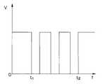
図1ないし図16は本発明の第1実施例に係わり、図1は第1実施例の手術用処置具を示す全体構図、図2は図1のA−A線断面図、図3は図2の変形例を示す断面図、図4は図1のB矢視図、図5は図1のC矢視図、図6は発熱体の斜視図、図7は図1の電源装置の回路ブロック図、図8ないし図12は図7の制御回路が行う出力制御を示すグラフであり、図8は時間に対する出力電圧を示すグラフ、図9は時間に対する出力電流を示すグラフ、図10は時間に対する出力電力を示すグラフ、図11は時間に対する発熱体の電気抵抗を示すグラフ、図12は時間に対する生体組織温度を示すグラフ、図13ないし図16は出力制御の変形例を示すグラフであり、図13は時間に対する出力電圧を示すグラフ、図14は時間に対する出力電流を示すグラフ、図15は時間に対する出力電力を示すグラフ、図16は時間に対する発熱体の電気抵抗を示すグラフである。 1 to 16 relate to a first embodiment of the present invention, FIG. 1 is an overall composition showing a surgical treatment instrument of the first embodiment, FIG. 2 is a sectional view taken along line AA in FIG. 1, and FIG. 4 is a cross-sectional view showing a modified example of FIG. 2, FIG. 4 is a view as seen from the arrow B in FIG. 1, FIG. 5 is a view as seen from the arrow C in FIG. FIG. 8 to FIG. 12 are graphs showing output control performed by the control circuit of FIG. 7, FIG. 8 is a graph showing output voltage with respect to time, FIG. 9 is a graph showing output current with respect to time, and FIG. FIG. 11 is a graph showing the electrical resistance of the heating element with respect to time, FIG. 12 is a graph showing the biological tissue temperature with respect to time, and FIGS. 13 to 16 are graphs showing variations of output control, FIG. 13 is a graph showing the output voltage against time, and FIG. 14 is the output current against time. Graph showing a graph showing the output power for 15 hours. FIG. 16 is a graph showing the electrical resistivity of the heating element with respect to time.
図1に示すように第1実施例の手術用処置具1は、把持した生体組織に熱を付与して凝固及び切開処置する鉗子2と、この鉗子2を着脱自在に接続可能で、この鉗子2に電源電力(電気エネルギ)を出力して駆動制御する電源装置3とを有している。 As shown in FIG. 1, the
前記鉗子2は、延出する接続コード4の後端部に設けたコネクタ(不図示)を前記電源装置3に着脱自在に接続するようになっている。
前記電源装置3には、フットスイッチ5が接続可能である。術者は、フットスイッチ5をオンオフすることで、前記鉗子2への電源電力のオンオフが行われるようになっている。尚、前記電源装置3のフロントパネルには、後述するパネル入力・表示部に前記鉗子2へ供給される電源電力の電流値や電圧値を表示する表示部や各種設置値を入力するための操作摘み等が設けられている。The
A
前記鉗子2は、術者が手に持って操作する一対のハンドル部11,12と、処置する生体組織を把持して凝固切開する一対のジョー13,14と、一対の鋏構成部材15,16とから主に構成されている。
前記ジョー13,14は、前記鉗子2の処置部2aを構成している。The
The
前記一対の鋏構成部材15,16は、それぞれハンドル部11,12とジョー13,14との間に設けられている。また、鋏構成部材15,16は、中途部分が略交差する状態に重ねられている。更に、鋏構成部材15,16の交差部は、これら鋏構成部材15,16を回動自在に連結する支点ピン17が設けられている。 The pair of
ハンドル部11,12には、指を掛ける手指挿入用のリング18,19が設けられている。鉗子2は、各々のリング18,19に例えば親指と薬指を通して開閉動作を行うと、それに連動してジョー13,14が開閉し、生体組織を把持、剥離、圧排操作するようになっている。即ち、一対のハンドル部11,12と一対の鋏構成部材15,16とは、鉗子2の操作部2bを構成している。 The
前記ジョー13は、生体組織に熱を付与するための後述の発熱体が埋め込まれており、この発熱体への電気信号を供給するための電源供給ライン21が前記鋏構成部材15内部に配設されている。尚、発熱体とは、後述するように薄膜抵抗や厚膜抵抗を発熱パターンとして表面にもつ発熱素子のことである。 The
この電源供給ライン21は、ジョー13からハンドル部11まで延出しており、リング18の後端側のコード接続部22から前記接続コード4を介して前記電源装置3に電気的に接続するようになっている。
手術用処置具1は、鉗子2が処置部2aにより生体組織を把持した後、電源装置3から電力を供給することで発熱体が発熱し、把持した生体組織に熱を付与して凝固及び切開処置を施すようになっている。The
In the
次に、手術用処置具1の各部の詳細構成を説明する。
先ず、処置部2aを説明する。
図2に示すように前記ジョー13には、前記ジョー14に対向する位置に、生体組織に熱を付与する発熱体23が設けられている。この発熱体23は、銅やモリブデン等の熱伝導率の高い材料から形成されている。前記発熱体23には、前記ジョー14に対向する面に比較的鈍な形状の組織押圧部24が形成されている。Next, the detailed configuration of each part of the
First, the treatment section 2a will be described.
As shown in FIG. 2, the
また、前記発熱体23の上側部分は、PTFE(ポリフッ化エチレン又は、ポリテトラフルオロエチレン)やPEEK(ポリエーテルエーテルケトン)等の熱伝導率が低く耐熱性の高い材料から形成される断熱部材25によって覆われている。
前記断熱部材25は、ジョー13の凹部に嵌め込まれた形で固定されている。これにより、前記発熱体23は、発生した熱を生体組織に効率良く付与すると共に、ステンレス等の金属材料から形成されている前記ジョー13が過度に熱くなるのを防止している。In addition, the upper portion of the
The
尚、前記発熱体23は、生体組織との接触部に生体組織の付着を防止するための、図示しないPTFE等の非粘着性の材料から形成されるコーティングが施されている。
一方、前記ジョー14には、前記発熱体23に対向する位置に受け部材26が一体的に設けられている。この受け部材26は、シリコンゴムやPTFE等の樹脂材料から形成されている。The
On the other hand, the
尚、処置部2aは、図3に示すように構成しても良い。
図3に示すように前記ジョー13には、発熱体23の組織押圧部24が、図2に比べてより鈍な形状として形成されている。また、前記ジョー14には、前記受け部材26に前記発熱体23の前記組織押圧部24と係合する凹部27が形成されている。The treatment section 2a may be configured as shown in FIG.
As shown in FIG. 3, the
尚、図2、図3で説明した以外にも、様々な形状、材質の発熱体23、及び受け部材26の組合せとすることができる。また、図4及び図5に示すように、前記ジョー13及び前記ジョー14は、先端に向かって湾曲した先細り形状となっている。 In addition to those described with reference to FIGS. 2 and 3, the
図6に示すように、前記ジョー13に設けた前記発熱体23の上面には、薄膜形成法(PVD( Physical Vapor Deposition )やCVD( Chemical Vapor Deposition )など)や厚膜形成法(スクリーン印刷など)により抵抗発熱体のパターン28が形成された薄膜基板23Aが設けられている。 As shown in FIG. 6, a thin film forming method (PVD (Physical Vapor Deposition) or the like) or a thick film forming method (screen printing or the like) is formed on the upper surface of the
前記パターン28は、通電することにより発熱する発熱領域28aと、非発熱領域であるリード線取付部28bとを有して構成されている。尚、前記パターン28は、温度に比例して電気抵抗が増加する、いわゆる正の温度係数を有するモリブデン等の高融点金属により形成されている。 The
前記鋏構成部材15内部に配設されている電源供給ライン21には、前記パターン28に電力を供給するためのリード線29が配設されている。これらリード線29の先端部は、前記パターン28のリード線取付け部28bに半田付けや熱圧着等により取り付けられている。尚、本実施例では、前記発熱体23上に前記パターン28が2個形成されており、これら2個のパターン28は、各々独立した出力制御がなされるよう、電源装置3にそれぞれ電気的に接続されている。 A
次に、前記電源装置3の内部構成を説明する。
前記電源装置3は、前記発熱体23を発熱させるための電力を供給する出力回路31と、前記発熱体23(パターン28)への印加電圧を検出する電圧検出部32と、前記発熱体23に流れる電流を検出する電流検出部33と、電圧、電流、電力、抵抗値等の各種パラメータを演算する演算回路34と、前記発熱体23へ供給される電源電力の電流値、電圧値の表示や各種設置値の入力を行うためのパネル入力・表示部35と、このパネル入力・表示部35により設定された各種設定値に従い、前記演算回路34の演算結果に基づいて前記出力回路31を制御する制御回路36と、を有して構成されている。Next, the internal configuration of the power supply device 3 will be described.
The power supply device 3 includes an
また、前記制御回路36には、フットスイッチ5が接続されており、フットスイッチ5のON、OFFに応じて出力回路31のON、OFFが制御されるようになっている。 In addition, a
電源装置3は、フットスイッチ5のON、OFFに応じて制御回路36が出力回路31のON、OFFを制御し、パネル入力・表示部35から入力された各種設定値と、演算回路34での演算結果である各パラメータ(電圧V、電流I、電力P、電気抵抗R)とを比較して出力回路31を制御することにより、発熱体23(パターン28)に対して後述の出力制御を行うようになっている。 In the power supply device 3, the
このように構成されている手術用処置具1は、図8〜図12に示すグラフのように制御されるようになっている。先ず、術者は、予めパネル入力・表示部35にて設定電圧V−set、及び上限温度T−limitを入力し設定を行う。The
術者は、鉗子2を持ち、ジョー13、14の間に生体組織を位置させ、この位置させた状態において、操作部2bを閉方向に操作して、発熱体23と受け部材26との間で生体組織を挟み込み把持する。次に術者は、フットスイッチ5を操作する。 The surgeon holds the
鉗子2は、電源装置3から接続コード4、コード接続部22、及びリード線29を介して発熱体23に電力が供給され、発熱体23が発熱する。 In the
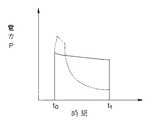
ここで、従来の定温度制御における電圧V、電流I、電力P、電気抵抗Rの変化、及び生体組織の温度変化を図8〜図12中に2点鎖線で示している。従来の定温度制御では、出力開始直後の供給電力は大きいが、発熱体が設定温度に到達した後の供給電力は大幅に低下する。 Here, changes in voltage V, current I, power P, electric resistance R, and temperature change of living tissue in conventional constant temperature control are shown by two-dot chain lines in FIGS. In the conventional constant temperature control, the supply power immediately after the start of output is large, but the supply power after the heating element reaches the set temperature is greatly reduced.
従って、従来の定温度制御では、生体組織が凝固作用温度に達した後、充分な電力が発熱体に供給されず、生体組織が切開作用温度に達するまで時間が掛かる。即ち、従来の定温度制御では、凝固は充分に行われるが、切開はゆっくり行われる。 Therefore, in the conventional constant temperature control, after the living tissue reaches the coagulation action temperature, sufficient power is not supplied to the heating element, and it takes time until the living tissue reaches the incision action temperature. That is, in the conventional constant temperature control, coagulation is sufficiently performed, but incision is performed slowly.
尚、切開を素早く行うため、発熱体の設定温度を高くすると、生体組織は、凝固作用温度で充分な時間保持されず、直ちに切開作用温度に到るため、生体組織の凝固はあまり行われない。即ち、従来の定温度制御では、生体組織を充分に凝固した状態で素早く切開を行うことが困難である。 In order to perform incision quickly, if the set temperature of the heating element is increased, the living tissue is not kept at the coagulation action temperature for a sufficient time, and the incision action temperature is reached immediately. . That is, with the conventional constant temperature control, it is difficult to make a quick incision while the living tissue is sufficiently solidified.
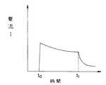
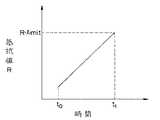
これに対して本実施例では、発熱体23への印可電圧Vを一定とし(定電圧制御)、発熱体23が予め設定した上限温度T−limitに達したとき出力回路31からの出力を停止するよう制御を行っている。即ち、フットスイッチ5をON(図8〜図12中の時間to)することにより、鉗子2には、図8に示すように発熱体23へ設定電圧V−setが印可される。発熱体23は、発熱を開始して温度が上昇すると共に、図11に示すようにパターン28の電気抵抗Rが増加する。In this embodiment the contrary, the applied voltage V to the
ここで、パターン28の電気抵抗Rが予め設定した閾値R−limit(=上限温度T−limitにおけるパターン28の抵抗値)に達したとき(図8〜図12中の時間t1)、制御回路36は、出力回路31からの出力を停止させる。尚、このとき、前記制御回路36は、T−limitからパターン28の閾値R−limitを換算している。In this case, upon reaching a thresholdR -limit the electric resistance R of the
これにより、発熱体23の温度は、予め設定した上限温度T−limitを超えることがない。尚、図9に示すように電源装置3からの電力出力中、発熱体23へ流れる電流Iは、徐々に減少する。
このため、図10に示すように発熱体23へ供給される電力Pは、時間経過と共に若干ではあるが減少することになるが、ほぼ一定の電力Pが発熱体23へ供給される。Accordingly, the temperature of the
For this reason, as shown in FIG. 10, the electric power P supplied to the
従って、生体組織が凝固作用温度で保持された後、充分な電力Pが発熱体23に供給されるので、短時間で生体組織は切開作用温度まで達する。これにより、鉗子2は、充分な凝固力を保ったまま、素早い切開を行うことが可能となる。
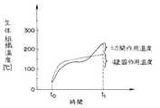
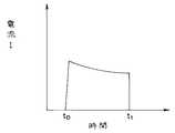
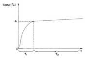
ここで、生体組織の温度は、図12に示すように発熱体23の発熱開始と共に、上昇する。その後、生体組織は、約100〜150℃付近で温度上昇が一旦鈍る。Therefore, after the living tissue is held at the coagulation temperature, sufficient electric power P is supplied to the
Here, the temperature of the living tissue rises with the start of heat generation of the
ここで、発熱体23へ供給された電力Pは、生体組織に含まれる水分を蒸発させるためのエネルギーとして消費される。尚、この間、生体組織には充分な凝固作用が生じる。生体組織に含まれる水分の蒸発が完了すると、生体組織の温度は、再度上昇を始める。生体組織が切開作用温度(約200℃付近)まで達した時点で、組織の切開が行われる。 Here, the electric power P supplied to the
これにより、手術用処置具1は、生体組織が充分に凝固した状態で素早く切開を行うことができるため、手術時間を短縮できる。また、手術用処置具1は、正の温度係数を有する発熱体23(パターン28)を使用しているため、温度コントロールが正確に行える。 Thereby, since the
従って、手術用処置具1は、発熱体の温度が過度に上昇することがないため、耐久性が良好であり、繰り返しての使用が可能となる。これにより、手術用処置具1は、低コストが実現可能となる。 Therefore, since the temperature of the heating element does not increase excessively, the
尚、図8〜図12に示す定電圧制御時、手術用処置具1は、鉗子2が生体組織を把持していない状態で電源装置3が出力開始した場合、発熱体23の温度が急上昇し、発熱体23に流れる電流Iが急激に減少してしまう。
そこで、制御回路36は、単位時間Δt当たりの電流変化量|ΔI÷Δt|を演算回路34により演算し、この電流変化量|ΔI÷Δt|が設定値を超えた場合、出力を停止するよう制御しても良い。尚、ここで、デルタΔは、差分を表している。8 to 12, when the power supply device 3 starts to output the
Therefore, the
これにより、手術用処置具1は、鉗子2が生体組織を把持していない状態での電源装置3からの出力を防止できるため、処置時の安全性を向上できる。更に、手術用処置具1は、発熱体23の急激な温度変化も防止できる。 Thereby, since the
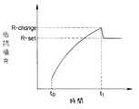
尚、手術用処置具1は、図13〜図16に示すような定温度制御を行っても良い。
本変形例では、発熱体23への印可電圧Vを一定とし(定電圧制御)、発熱体23が予め設定した切換温度T−changeに達した後、発熱体23を一定の設定温度T−setに保つ定温度制御を行っている。The
In this modification, the applied voltage V to the
即ち、制御回路36は、図13〜図16において、パターン28の電気抵抗Rが閾値R−change(=切換温度T−changeにおけるパターン28の抵抗値)に達した後(図13〜図16中の時間t1)、パターン28を一定の電気抵抗R−set(=設定温度T−setにおけるパターン28の抵抗値)に保つ制御をしている。That is, the
ここでも、手術用処置具1は、上記図8〜図12で説明した出力制御と同様に、充分な凝固力を保ったまま、素早い切開を行うことが可能となる。
尚、本変形例の制御を行うときは、術者は、予めパネル入力・表示部35にて設定電圧V−set、切換温度T−change、及び設定温度T−setを入力し設定を行う必要がある。また、図13〜図16に示した以外に、切換温度T−changeと設定温度T−setとの関係は、T−change=T−setでも良く、T−change<T−setでも良い。Here too, the
Incidentally, when performing control of the present modification, the operator needs to set the voltageV -set in advance the panel input and
図17ないし図20は本発明の第2実施例に係わる制御回路が行う出力制御を示すグラフであり、図17は時間に対する出力電圧を示すグラフ、図18は時間に対する出力電流を示すグラフ、図19は時間に対する出力電力を示すグラフ、図20は時間に対する発熱体の電気抵抗を示すグラフである。 17 to 20 are graphs showing the output control performed by the control circuit according to the second embodiment of the present invention. FIG. 17 is a graph showing the output voltage with respect to time. FIG. 18 is a graph showing the output current with respect to time. 19 is a graph showing the output power with respect to time, and FIG. 20 is a graph showing the electrical resistance of the heating element with respect to time.
上記第1実施例は定電圧制御を行うように構成しているが、第2実施例は定電流制御を行うように構成している。それ以外の構成は、上記第1実施例と同様な構成であるので、説明を省略し、同じ構成には同じ符号を付して説明する。 While the first embodiment is configured to perform constant voltage control, the second embodiment is configured to perform constant current control. Since the other configuration is the same as that of the first embodiment, the description will be omitted, and the same components will be described with the same reference numerals.
即ち、第2実施例の手術用処置具1は、図17〜図20に示すように、発熱体23に流れる電流Iを一定とし(定電流制御)、発熱体23が予め設定した上限温度T−limitに達したとき出力を停止する制御をしている。That is, as shown in FIGS. 17 to 20, the
更に、具体的に説明すると、制御回路36は、フットスイッチ5をON(図17〜図20中の時間to)することにより、発熱体23へは設定電流I−setが流れ、発熱体23は発熱を開始し温度が上昇する。また、発熱体23の温度上昇と共に、パターン28の電気抵抗Rは増加する。More specifically, the
ここで、制御回路36は、パターン28の電気抵抗Rが予め設定した閾値R−limit(=上限温度T−limitにおけるパターン28の抵抗値)に達したとき(図17〜図20中の時間のt1)、出力回路31からの出力を停止させる。これにより、発熱体23の温度は、予め設定した上限温度T−limitを超えることがない。尚、出力中、発熱体23に印可される電圧Vは、徐々に増加する。Here, the
この結果、発熱体23へ供給される電力Pは、時間経過と共に若干ではあるが増加することになるが、ほぼ一定の電力Pが発熱体23へ供給される。尚、生体組織の温度変化は、上記第1実施例で説明した図12と同様である。 As a result, the electric power P supplied to the
従って、手術用処置具1は、生体組織が凝固作用温度で保持された後、充分な電力Pが発熱体23に供給されるため、短時間で生体組織は切開作用温度まで達する。これにより、手術用処置具1は、充分な凝固力を保ったまま、素早い切開を行うことが可能となる。尚、第2実施例の制御を行うときは、術者は、予めパネル入力・表示部35にて設定電流I−set、及び上限温度T−limitを入力し設定を行う必要がある。Therefore, after the living tissue is held at the coagulation action temperature, the
尚、図9の定電流制御時、単位時間Δtあたりの電圧値変化量|ΔV÷Δt|を演算回路34により演算し、|ΔV÷Δt|が予め設定した値を超えた場合、出力を停止するように制御しても良い。 During constant current control in FIG. 9, the voltage value change amount | ΔV ÷ Δt | per unit time Δt is calculated by the
これにより、第2実施例は、上記第1実施例と同様に、生体組織を把持していない状態での出力を防止できるため、処置時の安全性を向上できる。更に、第2実施例の手術用処置具1は、発熱体23の急激な温度変化も防止できる。 Thereby, since the 2nd example can prevent the output in the state which is not grasping living tissue like the 1st example of the above, it can improve the safety at the time of treatment. Furthermore, the
また、第2実施例は、上記第1実施例と同様に、パネル入力・表示部35にて設定電流I−set、切換温度T−change、及び設定温度T−setの入力を行い、定電流制御に引き続いて定温度制御を行っても良い。
従って、第2実施例の手術用処置具1は、上記第1実施例と同様な効果を得ることができる。The second embodiment is similar to the first embodiment performs the set currentI -set at the panel input and
Therefore, the
図21ないし図24は本発明の第3実施例に係わる制御回路が行う出力制御を示すグラフであり、図21は時間に対する出力電圧を示すグラフ、図22は時間に対する出力電流を示すグラフ、図23は時間に対する出力電力を示すグラフ、図24は時間に対する発熱体の電気抵抗を示すグラフである。 21 to 24 are graphs showing the output control performed by the control circuit according to the third embodiment of the present invention. FIG. 21 is a graph showing the output voltage with respect to time. FIG. 22 is a graph showing the output current with respect to time. 23 is a graph showing the output power with respect to time, and FIG. 24 is a graph showing the electrical resistance of the heating element with respect to time.
上記第1実施例は定電圧制御を行うように構成しているが、第3実施例は定電力制御を行うように構成している。それ以外の構成は、上記第1実施例と同様な構成であるので、説明を省略し、同じ構成には同じ符号を付して説明する。 While the first embodiment is configured to perform constant voltage control, the third embodiment is configured to perform constant power control. Since the other configuration is the same as that of the first embodiment, the description will be omitted, and the same components will be described with the same reference numerals.
即ち、第3実施例の手術用処置具1は、図21〜図24に示すように、発熱体23に供給される電力Pを一定とし(定電力制御)、発熱体23が予め設定した上限温度T−limitに達したとき出力を停止するように制御をしている。That is, as shown in FIGS. 21 to 24, the
更に、具体的に説明すると、制御回路36は、フットスイッチ5をON(図21〜図24中の時間to)することにより、発熱体23へは設定電力P−setが供給され、発熱体23は発熱を開始し温度が上昇する。また、発熱体23の温度上昇と共に、パターン28の電気抵抗Rは、増加する。More specifically, when the
ここで、制御回路36は、パターン28の電気抵抗Rが予め設定した閾値R−limit(=上限温度T−limitにおけるパターン28の抵抗値)に達したとき(図21〜図24中の時間t1)、出力回路31からの出力を停止させる。
これにより、発熱体23の温度は、予め設定した上限温度T−limitを超えることはない。尚、出力中、発熱体23へ供給される電力Pは一定である。Here, the
Accordingly, the temperature of the
従って、手術用処置具1は、生体組織が凝固作用温度で保持された後、充分な電力Pが発熱体23に供給されるため、短時間で生体組織は切開作用温度まで達する。
これにより、手術用処置具1は、充分な凝固力を保ったまま、素早い切開を行うことが可能となる。Therefore, after the living tissue is held at the coagulation action temperature, the
Thereby, the
尚、第3実施例の制御を行うときは、術者は、予めパネル入力・表示部35にて設定電力P−set、及び上限温度T−limitを入力し設定を行う必要がある。尚、生体組織の温度変化は、上記第1実施例で説明した図12と同様である。Note that when performing the control of the third embodiment, the operatorneeds to input the setting power P-set and the upper limit temperature T-limit via the panel input /
ここで、フットスイッチ5をONしたとき、極短い時間(0.1秒程度)、発熱体23には微弱なモニタリング電流I−mが流れる。ここで、演算回路34にて出力開始時の開始電圧値V−startを計算する。開始電圧値V−startの計算式は以下に示す式1である。Here, when the

上記開始電圧V−startを印可することにより、手術用処置具1は、制御回路36による定電力制御が開始される。
これにより、第3実施例の手術用処置具1は、出力開始時に過度の電圧Vが発熱体23に印可されることはない。By applying the starting voltage V-start,
Thereby, in the
尚、第3実施例の手術用処置具1は、上記モニタリング電流I−mを常時供給しておき、フットスイッチ5のON後、直ちに定電力制御が開始されるようにしても良い。
また、第3実施例の手術用処置具1は、図21〜図24の定電力制御時、単位時間Δtあたりの抵抗変化量|ΔR÷Δt|を演算回路34により演算し、|ΔR÷Δt|が予め設定した値を超えた場合、出力を停止するように制御しても良い。Note that the
Further, the
これにより、第3実施例の手術用処置具1は、上記実施例1と同様に、生体組織を把持していない状態での出力を防止できるため、処置時の安全性を向上できる。更に、第3実施例の手術用処置具1は、発熱体23の急激な温度変化も防止できる。 As a result, the
また、第3実施例の手術用処置具1は、上記実施例1と同様に、予めパネル入力・表示部35にて設定電力P−set、切換温度T−change、及び設定温度T−setの入力を行い、定電力制御に引き続いて定温度制御を行っても良い。The
ところで、従来の手術用処置具には、特開平10−286260号公報に記載されているように、発熱によって生体組織の処置を行う発熱処置具が提案されている。上記公報に記載の手術用処置具は、発熱体の早期劣化を防止するため、空中発熱の防止制御を行っていた。 By the way, as described in Japanese Patent Application Laid-Open No. 10-286260, as a conventional surgical treatment tool, a heat treatment tool for treating a living tissue by heat generation has been proposed. The surgical treatment instrument described in the above publication performs prevention control of air heat generation in order to prevent premature deterioration of the heating element.
しかしながら、上記公報に記載の手術用処置具は、空中発熱に近い負荷の小さい状態(熱容量の小さい生体組織の処置)では発熱できないという問題があった。
また、上記公報には記載されていないが、電気抵抗により発熱する発熱体は出力時の電圧や電力が大きいと、瞬間的に超高温になる虞れがあった。
また、一般に、発熱体は、異なる材質の組み合わせから構成されるため、急激な温度差により材質間の熱膨張の差から歪が発生する虞れがあった。However, the surgical treatment instrument described in the above publication has a problem that heat cannot be generated in a state where the load is close to heat generation in the air (treatment of a biological tissue having a small heat capacity).
Further, although not described in the above publication, there is a possibility that a heating element that generates heat due to electric resistance may instantaneously become super high temperature when output voltage or power is large.
In general, since the heating element is composed of a combination of different materials, there is a risk that distortion may occur due to a difference in thermal expansion between the materials due to a rapid temperature difference.
そこで、負荷の大小・有無にかかわらず使用可能で、発熱体を良好な状態に維持可能な手術用処置具の提供が望まれていた。
このため、手術用処置具は、発熱体の定電圧制御において、発熱開始直後の出力電圧を徐々に増やす制御を行うように構成する。Therefore, it has been desired to provide a surgical treatment tool that can be used regardless of whether the load is large or small and can maintain the heating element in a good state.
For this reason, the surgical treatment instrument is configured to gradually increase the output voltage immediately after the start of heat generation in the constant voltage control of the heating element.
図25ないし図27は、発熱開始直後の出力電圧及び出力電力を徐々に増やす制御を行うためのグラフであり、図25は定電圧制御における発熱体への出力電圧を示したグラフ、図26は図25の第1の変形例を示すグラフ、図27は図25の第2の変形例を示すグラフである。 25 to 27 are graphs for performing control to gradually increase the output voltage and output power immediately after the start of heat generation, FIG. 25 is a graph showing the output voltage to the heating element in constant voltage control, and FIG. 25 is a graph showing a first modification of FIG. 25, and FIG. 27 is a graph showing a second modification of FIG.
図25に示すように、手術用処置具は、定電圧制御において、出力開始直後の所定時間T1、電圧が徐々に上昇し、T1経過後に所定電圧V1に到達する。(T1としては1ms〜1s程度である。)
この結果、手術用処置具は、出力直後の電圧を極短時間、徐々に上昇させることで、発熱体の温度を過度に上げることなく、また熱歪も少なくなる。これにより、手術用処置具は、発熱体の耐久性が向上する。As shown in FIG. 25, in the surgical treatment instrument, in the constant voltage control, the voltage gradually increases for a predetermined time T1 immediately after the start of output, and reaches the predetermined voltage V1 after T1 elapses. (T1 is about 1 ms to 1 s.)
As a result, the surgical treatment instrument gradually raises the voltage immediately after the output for a very short time, so that the temperature of the heating element is not excessively raised and thermal distortion is reduced. Thereby, the durability of a heat generating body improves the treatment tool for surgery.
また、図26に示すように手術用処置具は、出力開始後の電圧の変化を時間的に更に分割して制御するようにしても良い。
即ち、図26に示すように手術用処置具は、出力開始後の電圧の変化を時間的に更に分割し、出力開始直後及び所定電圧V1到達時に滑らかに変化する。Further, as shown in FIG. 26, the surgical treatment instrument may be controlled by further dividing the voltage change after the start of output in terms of time.
That is, as shown in FIG. 26, the surgical treatment instrument further divides the change in voltage after the start of output in terms of time, and changes smoothly immediately after the start of output and when the predetermined voltage V1 is reached.
また、図27に示すように手術用処置具は、出力開始直後の出力電力を変化させて制御するようにしても良い。
図27に示すように手術用処置具は、定電力制御において、出力開始直後の出力電力を変化させている。尚、図27に示す定電力制御の場合も図25の定電圧制御のように出力時の電力変化を更に分割して制御しても良い。また、図示しないが、定電流制御において、出力開始直後の出力電流を徐々に増やす制御を行っても良い。In addition, as shown in FIG. 27, the surgical treatment instrument may be controlled by changing the output power immediately after the start of output.
As shown in FIG. 27, the surgical treatment instrument changes the output power immediately after the start of output in the constant power control. In the case of the constant power control shown in FIG. 27, the power change at the time of output may be further divided and controlled as in the constant voltage control of FIG. Although not shown, in constant current control, control may be performed to gradually increase the output current immediately after the start of output.
ところで、従来の手術用処置具は、発熱体を用いた場合、印加する電力を定温度やパルス印加などの制御により発熱体に供給していた。
しかしながら、従来の手術用処置具は、確実な生体組織の凝固ができないうちに、切開が起きてしまったり、処置時間が延びてしまうという問題があった。By the way, when a conventional surgical treatment instrument uses a heating element, the power to be applied is supplied to the heating element by control such as constant temperature or pulse application.
However, the conventional surgical treatment tool has a problem in that an incision occurs or treatment time is extended before solidification of a living body tissue is not possible.
そこで、確実な生体組織の凝固が可能な手術用処置具の提供が望まれていた。
このため、手術用処置具は、電力出力時、定電圧制御し、発熱体の温度を効率良く上昇させ、その後、パルスで印加する制御を行うように構成する。Therefore, it has been desired to provide a surgical treatment instrument capable of reliably coagulating a living tissue.
For this reason, the surgical treatment instrument is configured to perform constant voltage control at the time of power output, to efficiently raise the temperature of the heating element, and then to control by applying pulses.
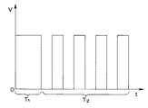
図28ないし図35は、電力出力時、定電圧制御し、発熱体の温度を効率良く上昇させ、その後、パルスで印加する電力供給制御のグラフであり、図28は時間に対する電圧制御を示すグラフ、図29は図28の第1の変形例を示すグラフ、図30は図28の第2の変形例を示すグラフ、図31は熱的負荷が大きい場合の時間に対する電圧制御を示すグラフ、図32は熱的負荷が小さい場合の時間に対する電圧制御を示すグラフ、図33は時間に対する累積投入熱量制御を示すグラフ、図34は時間に対する発熱体又は生体組織の温度制御を示すグラフ、図35は時間に対する電圧制御を示すグラフである。 FIG. 28 to FIG. 35 are graphs of power supply control in which constant voltage control is performed at the time of power output, the temperature of the heating element is efficiently raised, and then applied in pulses, and FIG. 28 is a graph showing voltage control with respect to time. 29 is a graph showing the first modification of FIG. 28, FIG. 30 is a graph showing the second modification of FIG. 28, FIG. 31 is a graph showing voltage control over time when the thermal load is large, and FIG. 32 is a graph showing voltage control with respect to time when the thermal load is small, FIG. 33 is a graph showing cumulative input heat amount control with respect to time, FIG. 34 is a graph showing temperature control of the heating element or biological tissue with respect to time, and FIG. It is a graph which shows the voltage control with respect to time.
図28に示すように手術用処置具は、電源装置が出力開始後、時間T1の間、定電圧制御により駆動されて、発熱体の温度を上昇させる。
任意の時間T1が経過した後、時間T2の間、パルス制御に切り換えて発熱体に供給するエネルギーを定電圧制御より減少させる。
これにより、手術用処置具は、生体組織の温度上昇を緩やかにし、生体組織の炭化が発生せずに確実な凝固が可能である。尚、出力のパラメータとしては、図29に示すように電力制御であっても良い。As shown in FIG. 28, the surgical treatment instrument is driven by constant voltage control for a time T1 after the power supply device starts to output, thereby raising the temperature of the heating element.
After an arbitrary time T1, the energy supplied to the heating element is reduced from the constant voltage control by switching to the pulse control for the time T2.
As a result, the surgical treatment tool can moderately increase the temperature of the living tissue and reliably coagulate without carbonization of the living tissue. The output parameter may be power control as shown in FIG.
また、図30に示すように定電圧制御からパルス制御への切り換わりは、発熱体の温度又は生体組織の温度をモニタする機能を電源に設け、前記温度が任意の閾値Aに達した時点で定電圧制御からパルス制御へと電源の出力制御を切り替えても良い。尚、閾値は、図示しないが温度だけではなく、出力開始からの時間や、出力開始からの累積投入熱量の値であっても良い。 In addition, as shown in FIG. 30, switching from constant voltage control to pulse control is performed by providing a power source with a function of monitoring the temperature of the heating element or the temperature of the living tissue, and when the temperature reaches an arbitrary threshold A. The power supply output control may be switched from constant voltage control to pulse control. Although not shown, the threshold value may be not only the temperature but also the time from the start of output and the value of the cumulative input heat amount from the start of output.
これにより、手術用処置具は、出力開始直後、発熱体が生体組織を処置するのに適した温度に達するために、定電圧若しくは定電力制御により、すばやく所望の温度にすることが可能である。所望の温度に達した後、手術用処置具は、生体組織の過加熱を防止するために、パルス制御により出力を行うことで、生体組織への熱付与を最小限にした上で確実な凝固を可能とする。
この結果、手術用処置具は、生体組織の炭化を生じさせることなく、確実な凝固が可能である。As a result, immediately after the start of output, the surgical treatment tool can quickly reach a desired temperature by constant voltage or constant power control in order to reach a temperature suitable for the heating element to treat the living tissue. . After reaching the desired temperature, the surgical treatment instrument performs output by pulse control in order to prevent overheating of the living tissue, thereby ensuring reliable coagulation while minimizing the application of heat to the living tissue. Is possible.
As a result, the surgical treatment tool can be reliably solidified without causing carbonization of the living tissue.
尚、発熱体にかかる熱的負荷は、処置具の構成、組織の状態によって異なる。このため、パルス制御のON−OFF時間の比(Duty比と呼ぶ)は、一つの設定で異なる生体組織の処置を行った場合、最適な設定になるとは限らない。
そこで、手術用処置具は、発熱体にかかる熱的負荷の大小により、術者が電源の設定によってDuty比を選択できるように構成する。Note that the thermal load applied to the heating element varies depending on the configuration of the treatment instrument and the state of the tissue. For this reason, the ON / OFF time ratio of pulse control (referred to as the duty ratio) is not always optimal when different biological tissues are treated with one setting.
Therefore, the surgical treatment tool is configured so that the surgeon can select the duty ratio according to the setting of the power source depending on the thermal load applied to the heating element.
即ち、手術用処置具は、術者による電源設定の選択により、熱的負荷が大きい場合、図31のようにDuty比のON時間の割合を大きくし、負荷が小さい場合は図32のようにON時間の割合を小さくするようにしている。
これにより、手術用処置具は、生体組織や、処置具に応じて最適な設定を選択可能であり、生体組織の炭化を生じさせることなく、確実な凝固が可能である。That is, the surgical treatment instrument increases the ON ratio of the duty ratio as shown in FIG. 31 when the thermal load is large due to the selection of the power supply setting by the operator, and as shown in FIG. 32 when the load is small. The ratio of ON time is made small.
As a result, the surgical treatment tool can select an optimal setting according to the living tissue and the treatment tool, and can be reliably solidified without causing carbonization of the living tissue.
尚、手術用処置具は、生体組織へ出力する累積投入熱量をモニタするための機能(不図示)を電源装置に設けて構成しても良い。
この場合、図33に示すように累積投入熱量が任意の閾値B2を超えた時点で出力を停止する。又は、任意の累積投入熱量B1を超えてパルス制御に切り換わってから任意の時間T2が経過した時点で出力を停止しても良い。同様に、図34に示すように累積投入熱量ではなく、発熱体の温度又は生体組織の温度に閾値A1、A2を設けても良い。
これにより、手術用処置具は、電源装置からの出力を自動的に停止することができ、生体組織の炭化を生じさせることなく、確実な凝固が可能である。Note that the surgical treatment instrument may be configured by providing a power supply device with a function (not shown) for monitoring the cumulative amount of heat input to the living tissue.
In this case, as shown in FIG. 33, the output is stopped when the cumulative input heat amount exceeds an arbitrary threshold value B2. Alternatively, the output may be stopped when an arbitrary time T2 elapses after switching to pulse control exceeding an arbitrary accumulated input heat amount B1. Similarly, as shown in FIG. 34, threshold values A1 and A2 may be provided not on the cumulative input heat amount but on the temperature of the heating element or the temperature of the living tissue.
Thus, the surgical treatment tool can automatically stop the output from the power supply device, and can be surely coagulated without causing carbonization of the living tissue.
尚、手術用処置具は、 図35に示すように上記図28から図34の制御を組み合わせて構成しても良い。
即ち、 図35に示すように手術用処置具は、出力開始後から任意の時刻t1までの間、定電圧制御により、発熱体の温度を上昇させる。手術用処置具は、任意の時刻t1を過ぎると定電圧制御からパルス制御に切り換える。The surgical treatment tool may be configured by combining the controls shown in FIGS. 28 to 34 as shown in FIG.
That is, as shown in FIG. 35, the surgical treatment instrument raises the temperature of the heating element by constant voltage control from the start of output until an arbitrary time t1. The surgical treatment instrument switches from constant voltage control to pulse control after an arbitrary time t1.
このとき、時刻t1の設定は、図30で説明したのと同様に、発熱体又は生体組織の温度に閾値を設けても良く、また、図33で説明したのと同様に、累積投入熱量に閾値を設けても良い。又は、時刻t1の設定は、予め設定できるようにしても良い。 At this time, the time t1 may be set by setting a threshold value for the temperature of the heating element or the living tissue as described with reference to FIG. 30. Also, as described with reference to FIG. A threshold may be provided. Alternatively, the time t1 may be set in advance.
また、パルス制御は、図31,図32で説明したのと同様に、術者がDuty比を選択できるようになっている。
手術用処置具は、パルス制御開始後、任意の時刻t2までパルス制御を継続し、時刻t2経過後、再び定電圧制御に切り換えて、発熱体の温度を上昇させるに伴って生体組織の切開を行うようにしている。尚、時刻t2の設定は、時刻t1と同様に、温度や投入熱量に閾値を設けても良いし、予め設定できるようにしても良い。また、出力のパラメータは、電圧でも電力でも電流でも良い。Further, in the pulse control, the surgeon can select the duty ratio as described with reference to FIGS.
The surgical treatment instrument continues the pulse control until an arbitrary time t2 after the start of the pulse control. After the time t2, the operation tool is switched to the constant voltage control again and the incision of the living tissue is performed as the temperature of the heating element increases. Like to do. The time t2 may be set by setting a threshold value for the temperature and input heat amount, or may be set in advance, similarly to the time t1. The output parameter may be voltage, power, or current.
手術用処置具は、定電圧、パルス、定電圧の制御を自動的に切り換え、発熱体の温度上昇、生体組織の凝固、生体組織の切開の順で処置を行うことが可能である。
これにより、手術用処置具は、生体組織の熱損傷を最小限にしながら確実な凝固と切開が同時にできる。The surgical treatment tool can automatically switch between constant voltage, pulse, and constant voltage control, and can perform treatment in the order of temperature rise of the heating element, coagulation of the living tissue, and incision of the living tissue.
As a result, the surgical treatment instrument can perform reliable coagulation and incision simultaneously while minimizing thermal damage to the living tissue.
尚、本発明は、以上述べた実施例のみに限定されるものではなく、発明の要旨を逸脱しない範囲で種々変形実施可能である。 The present invention is not limited to the above-described embodiments, and various modifications can be made without departing from the spirit of the invention.
[付記]
(付記項1)
先端側に生体組織を処置するための処置部を有し、この処置部に前記生体組織に付与する熱を発生するための発熱体を設けた鉗子と、
前記鉗子の前記発熱体にほぼ一定の電力を供給し、この発熱体の温度が所定温度に達したとき、前記発熱体への電力供給を停止するか又は、前記発熱体の温度を設定温度に保つ定温度制御に切り換える制御を行う電源装置と、
を具備したことを特徴とする手術用処置具。[Appendix]
(Additional item 1)
A forceps having a treatment part for treating the living tissue on the distal end side and provided with a heating element for generating heat applied to the living tissue in the treatment part;
When a substantially constant power is supplied to the heating element of the forceps and the temperature of the heating element reaches a predetermined temperature, the power supply to the heating element is stopped or the temperature of the heating element is set to a set temperature. A power supply device that performs control to switch to constant temperature control to be maintained;
A surgical treatment instrument comprising:
(付記項2)
前記発熱体は、温度に比例して電気抵抗が変化する温度係数を有し、
前記電源装置は、前記発熱体の電気抵抗から前記発熱体の温度を換算し、前記発熱体の電気抵抗が所定値に達したとき、前記発熱体の温度が前記所定温度に達したと判断し、前記発熱体への電力供給を停止するか又は、前記発熱体の温度を前記設定温度に保つ定温度制御に切り換える制御を行う
ことを特徴とする請求項1に記載の手術用処置具。(Appendix 2)
The heating element has a temperature coefficient in which electric resistance changes in proportion to temperature,
The power supply device converts the temperature of the heating element from the electrical resistance of the heating element, and determines that the temperature of the heating element has reached the predetermined temperature when the electrical resistance of the heating element reaches a predetermined value. 2. The surgical instrument according to
(付記項3)
前記電源装置は、前記発熱体に印加する電圧又は、前記発熱体に供給する電流又は、前記発熱体の電気抵抗の何れか1つの変化量が所定値を超えたとき、前記鉗子が前記生体組織を処置していないとして前記発熱体への電力供給を停止することを特徴とする請求項1に記載の手術用処置具。(Additional Item 3)
When the amount of change in any one of a voltage applied to the heating element, a current supplied to the heating element, or an electric resistance of the heating element exceeds a predetermined value, the power supply device The surgical treatment tool according to
(付記項4)
前記電源装置は、前記発熱体への出力開始直前、又は出力開始直後に前記発熱体に微弱なモニタリング電流を供給し、このモニタリング電流から得た前記発熱体に印加する電圧及び、前記発熱体に供給する電流及び、設定電力値から前記発熱体へ印加する電圧値を演算してこの演算した電圧値に基づいて前記発熱体への電力供給を開始することを特徴とする付記項1に記載の手術用処置具。(Appendix 4)
The power supply device supplies a weak monitoring current to the heating element immediately before the start of output to the heating element, or immediately after the start of output, and the voltage applied to the heating element obtained from the monitoring current and the
(付記項5)
前記電源装置は、前記発熱体の温度が所定温度に達するまで、前記発熱体に一定の電圧を印加する定電圧制御又は、前記発熱体に一定の電流を供給する定電流制御又は前記発熱体に一定の電力を供給する定電力制御を行うことを特徴とする付記項1に記載の手術用処置具。(Appendix 5)
The power supply device includes constant voltage control for applying a constant voltage to the heating element until the temperature of the heating element reaches a predetermined temperature, constant current control for supplying a constant current to the heating element, or the heating element. The surgical treatment tool according to
(付記項6)
前記鉗子は、前記処置部として開閉可能な一対の把持部を先端側に有すると共に、基端側に前記把持部を開閉操作するための操作部を有し、
前記発熱体は、前記鉗子の前記把持部の少なくとも一方に設けたことを特徴とする付記項1に記載の手術用処置具。(Appendix 6)
The forceps has a pair of gripping portions that can be opened and closed as the treatment portion on the distal end side, and an operation portion for opening and closing the gripping portion on the proximal end side,
The surgical treatment tool according to
(付記項7)
前記電源装置は、前記鉗子の前記発熱体にほぼ一定の電力を供給する制御は、前記発熱体に一定の電圧を印加する定電圧制御又は、前記発熱体に一定の電流を供給する定電流制御であることを特徴とする付記項1に記載の手術用処置具。(Appendix 7)
The power supply device is controlled to supply substantially constant power to the heating element of the forceps, constant voltage control to apply a constant voltage to the heating element, or constant current control to supply a constant current to the heating element. The surgical treatment tool according to
(付記項8)
前記電源装置は、前記発熱体の電気抵抗を演算する演算回路を有し、この演算回路の演算結果に基づき、前記発熱体への電力供給を停止するか又は、前記発熱体の温度を設定温度に保つ定温度制御に切り換えることを特徴とする付記項1に記載の手術用処置具。(Appendix 8)
The power supply device has an arithmetic circuit for calculating the electric resistance of the heating element, and based on the calculation result of the arithmetic circuit, the power supply to the heating element is stopped or the temperature of the heating element is set to a set temperature. The surgical treatment instrument according to
(付記項9)
前記電源装置は、前記発熱体に印加する電圧又は、前記発熱体に供給する電流又は、これら電圧及び電流から算出した前記発熱体の電気抵抗の何れか1つの単位時間当たりの変化量を演算する演算回路を有し、この演算回路で演算した変化量が所定値を超えたとき、前記鉗子が前記生体組織を処置していないとして前記発熱体への電力供給を停止することを特徴とする付記項1に記載の手術用処置具。(Appendix 9)
The power supply device calculates a change amount per unit time of any one of a voltage applied to the heating element, a current supplied to the heating element, or an electric resistance of the heating element calculated from these voltage and current. And an arithmetic circuit, and when the amount of change calculated by the arithmetic circuit exceeds a predetermined value, the power supply to the heating element is stopped assuming that the forceps are not treating the living tissue.
(付記項10)
前記電源装置は、前記発熱体に印加する電圧及び、前記発熱体に供給する電流及び、設定電力値から前記発熱体へ印加する電圧値を演算する演算回路を有し、
前記発熱体への出力開始直前、又は出力開始直後に前記発熱体に微弱なモニタリング電流を供給し、このモニタリング電流から前記演算回路により前記演算した電圧値に基づいて前記発熱体への電力供給を開始することを特徴とする付記項1に記載の手術用処置具。(Appendix 10)
The power supply device includes an arithmetic circuit that calculates a voltage applied to the heating element, a current supplied to the heating element, and a voltage value applied to the heating element from a set power value,
A weak monitoring current is supplied to the heating element immediately before the start of output to the heating element or immediately after the start of output, and power is supplied to the heating element from the monitoring current based on the voltage value calculated by the arithmetic circuit. The surgical treatment tool according to
(付記項11)
前記電源装置は、前記発熱体に印加される電圧を検出する電圧検出手段及び、前記発熱体に供給する電流を検出する電流検出手段を有し、
前記演算回路は、前記電圧検出手段で検出された電圧及び前記電流検出手段で検出された電流から前記発熱体の前記電気抵抗値を演算する
ことを特徴とする付記項7〜10に記載の手術用処置具。(Appendix 11)
The power supply device includes voltage detection means for detecting a voltage applied to the heating element, and current detection means for detecting a current supplied to the heating element,
The operation according to any one of claims 7 to 10, wherein the arithmetic circuit calculates the electrical resistance value of the heating element from the voltage detected by the voltage detection means and the current detected by the current detection means. Treatment tool.
(付記項12)
先端部に開閉可能な一対の把持部からなる処置部と、基端部に前記把持部を開閉操作する操作部を有し、前記把持部の少なくとも一方に生体組織を処置するための発熱部を設けた鉗子と、前記発熱部を駆動、制御するための電源装置とからなる手術用処置具において、
前記発熱部は、温度係数を有する発熱体からなり、
前記電源装置は、前記発熱体にほぼ一定の電力を供給するように駆動、制御する
ことを特徴とする手術用処置具。(Appendix 12)
A treatment part comprising a pair of gripping parts that can be opened and closed at the distal end part, and an operation part for opening and closing the gripping part at the proximal end part, and a heat generating part for treating living tissue on at least one of the gripping parts In a surgical treatment instrument comprising a provided forceps and a power supply device for driving and controlling the heat generating portion,
The heating part is composed of a heating element having a temperature coefficient,
The surgical power tool, wherein the power supply device is driven and controlled so as to supply substantially constant power to the heating element.
(付記項13)
前記電源装置は、前記発熱体に一定の電圧を印加するように駆動、制御することを特徴とする付記項12に記載の手術用処置具。(Appendix 13)
The surgical treatment tool according to
(付記項14)
前記電源装置は、前記発熱体に一定の電流が流れるように駆動、制御することを特徴とする付記項12に記載の手術用処置具。(Appendix 14)
The surgical treatment tool according to
(付記項15)
前記電源装置は、発熱体に印加される電圧を検出する電圧検出手段と、発熱体に流れる電流を検出する電流検出手段と、前記検出された電圧及び電流から発熱体に供給される電力及び発熱体の電気抵抗を演算する演算回路とを有し、前記演算回路の演算結果に基づき、前記発熱体に定電圧駆動、又は定電流駆動、又は定電力駆動する出力制御を行うことを特徴とする付記項12に記載の手術用処置具。(Appendix 15)
The power supply device includes a voltage detection unit that detects a voltage applied to the heating element, a current detection unit that detects a current flowing through the heating element, and an electric power and heat generation that are supplied to the heating element from the detected voltage and current. And an output circuit for performing constant voltage drive, constant current drive, or constant power drive on the heating element based on the calculation result of the calculation circuit. The surgical treatment tool according to
(付記項16)
前記電源装置は、前記発熱体が予め設定した温度に達したとき、前記発熱体への電力供給を停止することを特徴とする付記項15に記載の手術用処置具。(Appendix 16)
The surgical treatment tool according to
(付記項17)
前記電源装置は、前記発熱体が予め設定した温度に達したとき、前記発熱体の温度を一定に保つ定温度制御駆動に切り換わることを特徴とする付記項15に記載の手術用処置具。(Appendix 17)
The surgical power tool according to
(付記項18)
前記演算回路は、電圧又は電流又は電気抵抗の何れかの単位時間当たりの変化量を演算し、前記変化量が予め設定した値を超えたとき、前記発熱体への電力供給を停止することを特徴とする付記項15に記載の手術用処置具。(Appendix 18)
The arithmetic circuit calculates the amount of change per unit time of voltage, current, or electrical resistance, and stops supplying power to the heating element when the amount of change exceeds a preset value. The surgical treatment tool according to
(付記項19)
前記電源装置は、前記発熱体を定電力駆動する出力制御を行う際、出力開始直前、又は出力開始直後に前記発熱体に微弱なモニタリング電流を流し、
前記演算回路は、電圧、電流、及び設定電力値から前記定電力駆動開始時の電圧値を演算することを特徴とする付記項15に記載の手術用処置具。(Appendix 19)
The power supply device, when performing output control for driving the heating element at a constant power, allows a weak monitoring current to flow through the heating element immediately before starting output or immediately after starting output,
16. The surgical treatment tool according to
1 手術用処置具
2 鉗子
2a 処置部
2b 操作部
3 電源装置
11,12 ハンドル部
13,14 ジョー
15,16 鋏構成部材
23 発熱体
23A 薄膜基板
24 組織押圧部
25 断熱部材
26 受け部材
28 パターン
31 出力回路
32 電圧検出部
33 電流検出部
34 演算回路
35 パネル入力・表示部
36 制御回路
代理人 弁理士 伊藤 進DESCRIPTION OF
Claims (3)
Translated fromJapanese前記鉗子の前記発熱体にほぼ一定の電力を供給し、この発熱体の温度が所定温度に達したとき、前記発熱体への電力供給を停止するか又は、前記発熱体の温度を設定温度に保つ定温度制御に切り換える制御を行う電源装置と、
を具備したことを特徴とする手術用処置具。A forceps having a treatment part for treating the living tissue on the distal end side and provided with a heating element for generating heat applied to the living tissue in the treatment part;
When a substantially constant power is supplied to the heating element of the forceps and the temperature of the heating element reaches a predetermined temperature, the power supply to the heating element is stopped or the temperature of the heating element is set to a set temperature. A power supply device that performs control to switch to constant temperature control to be maintained;
A surgical treatment instrument comprising:
前記電源装置は、前記発熱体の電気抵抗から前記発熱体の温度を換算し、前記発熱体の電気抵抗が所定値に達したとき、前記発熱体の温度が前記所定温度に達したと判断し、前記発熱体への電力供給を停止するか又は、前記発熱体の温度を前記設定温度に保つ定温度制御に切り換える制御を行う
ことを特徴とする請求項1に記載の手術用処置具。The heating element has a temperature coefficient in which electric resistance changes in proportion to temperature,
The power supply device converts the temperature of the heating element from the electrical resistance of the heating element, and determines that the temperature of the heating element has reached the predetermined temperature when the electrical resistance of the heating element reaches a predetermined value. 2. The surgical instrument according to claim 1, wherein power supply to the heating element is stopped, or control is performed to switch to constant temperature control that maintains the temperature of the heating element at the set temperature.
When the amount of change in any one of a voltage applied to the heating element, a current supplied to the heating element, or an electric resistance of the heating element exceeds a predetermined value, the power supply device The surgical treatment tool according to claim 1, wherein power supply to the heating element is stopped because no treatment is performed.
Priority Applications (4)
| Application Number | Priority Date | Filing Date | Title |
|---|---|---|---|
| JP2004071405AJP4624697B2 (en) | 2004-03-12 | 2004-03-12 | Surgical instrument |
| EP05005029.3AEP1582165B1 (en) | 2004-03-12 | 2005-03-08 | Operative instrument with heat-generating body |
| US11/077,861US20050222560A1 (en) | 2004-03-12 | 2005-03-11 | Operative instrument |
| US12/852,766US20100305558A1 (en) | 2004-03-12 | 2010-08-09 | Operative instrument |
Applications Claiming Priority (1)
| Application Number | Priority Date | Filing Date | Title |
|---|---|---|---|
| JP2004071405AJP4624697B2 (en) | 2004-03-12 | 2004-03-12 | Surgical instrument |
Publications (2)
| Publication Number | Publication Date |
|---|---|
| JP2005253789Atrue JP2005253789A (en) | 2005-09-22 |
| JP4624697B2 JP4624697B2 (en) | 2011-02-02 |
Family
ID=34879870
Family Applications (1)
| Application Number | Title | Priority Date | Filing Date |
|---|---|---|---|
| JP2004071405AExpired - Fee RelatedJP4624697B2 (en) | 2004-03-12 | 2004-03-12 | Surgical instrument |
Country Status (3)
| Country | Link |
|---|---|
| US (2) | US20050222560A1 (en) |
| EP (1) | EP1582165B1 (en) |
| JP (1) | JP4624697B2 (en) |
Cited By (182)
| Publication number | Priority date | Publication date | Assignee | Title |
|---|---|---|---|---|
| JP2007195981A (en)* | 2006-01-24 | 2007-08-09 | Sherwood Services Ag | Method and system for controlling delivery of energy to divide tissue |
| JP2010538796A (en)* | 2007-09-18 | 2010-12-16 | サージレックス・インコーポレイテッド | Electrosurgical instrument and method |
| WO2013088890A1 (en)* | 2011-12-12 | 2013-06-20 | オリンパスメディカルシステムズ株式会社 | Treatment system, and control method for treatment system |
| WO2013088892A1 (en)* | 2011-12-12 | 2013-06-20 | オリンパスメディカルシステムズ株式会社 | Treatment system and method for controlling treatment system |
| US8523898B2 (en) | 2009-07-08 | 2013-09-03 | Covidien Lp | Endoscopic electrosurgical jaws with offset knife |
| US8540712B2 (en) | 2010-08-20 | 2013-09-24 | Covidien Lp | Surgical instrument configured for use with interchangeable hand grips |
| US8568444B2 (en) | 2008-10-03 | 2013-10-29 | Covidien Lp | Method of transferring rotational motion in an articulating surgical instrument |
| US8591506B2 (en) | 1998-10-23 | 2013-11-26 | Covidien Ag | Vessel sealing system |
| US8597296B2 (en) | 2003-11-17 | 2013-12-03 | Covidien Ag | Bipolar forceps having monopolar extension |
| US8679140B2 (en) | 2012-05-30 | 2014-03-25 | Covidien Lp | Surgical clamping device with ratcheting grip lock |
| CN103747755A (en)* | 2011-12-12 | 2014-04-23 | 奥林巴斯医疗株式会社 | Treatment system and control method for treatment system |
| US8747434B2 (en) | 2012-02-20 | 2014-06-10 | Covidien Lp | Knife deployment mechanisms for surgical forceps |
| US8764749B2 (en) | 2008-04-22 | 2014-07-01 | Covidien | Jaw closure detection system |
| US8864753B2 (en) | 2011-12-13 | 2014-10-21 | Covidien Lp | Surgical Forceps Connected to Treatment Light Source |
| US8887373B2 (en) | 2012-02-24 | 2014-11-18 | Covidien Lp | Vessel sealing instrument with reduced thermal spread and method of manufacture therefor |
| US8920461B2 (en) | 2012-05-01 | 2014-12-30 | Covidien Lp | Surgical forceps with bifurcated flanged jaw components |
| US8939975B2 (en) | 2012-07-17 | 2015-01-27 | Covidien Lp | Gap control via overmold teeth and hard stops |
| US8968313B2 (en) | 2012-06-12 | 2015-03-03 | Covidien Lp | Electrosurgical instrument with a knife blade stop |
| US8968309B2 (en) | 2011-11-10 | 2015-03-03 | Covidien Lp | Surgical forceps |
| US8968311B2 (en) | 2012-05-01 | 2015-03-03 | Covidien Lp | Surgical instrument with stamped double-flag jaws and actuation mechanism |
| US8968306B2 (en) | 2011-08-09 | 2015-03-03 | Covidien Lp | Surgical forceps |
| USD726910S1 (en) | 2013-08-07 | 2015-04-14 | Covidien Lp | Reusable forceps for open vessel sealer with mechanical cutter |
| US9011436B2 (en) | 2012-06-26 | 2015-04-21 | Covidien Lp | Double-length jaw system for electrosurgical instrument |
| US9011435B2 (en) | 2012-02-24 | 2015-04-21 | Covidien Lp | Method for manufacturing vessel sealing instrument with reduced thermal spread |
| US9024237B2 (en) | 2009-09-29 | 2015-05-05 | Covidien Lp | Material fusing apparatus, system and method of use |
| USD728786S1 (en) | 2013-05-03 | 2015-05-05 | Covidien Lp | Vessel sealer with mechanical cutter and pistol-grip-style trigger |
| US9034009B2 (en) | 2012-05-01 | 2015-05-19 | Covidien Lp | Surgical forceps |
| US9033981B2 (en) | 2008-12-10 | 2015-05-19 | Covidien Lp | Vessel sealer and divider |
| US9039691B2 (en) | 2012-06-29 | 2015-05-26 | Covidien Lp | Surgical forceps |
| US9039731B2 (en) | 2012-05-08 | 2015-05-26 | Covidien Lp | Surgical forceps including blade safety mechanism |
| US9060780B2 (en) | 2011-09-29 | 2015-06-23 | Covidien Lp | Methods of manufacturing shafts for surgical instruments |
| US9072524B2 (en) | 2012-06-29 | 2015-07-07 | Covidien Lp | Surgical forceps |
| USD736920S1 (en) | 2013-08-07 | 2015-08-18 | Covidien Lp | Open vessel sealer with mechanical cutter |
| US9113941B2 (en) | 2009-08-27 | 2015-08-25 | Covidien Lp | Vessel sealer and divider with knife lockout |
| US9113901B2 (en) | 2012-05-14 | 2015-08-25 | Covidien Lp | Modular surgical instrument with contained electrical or mechanical systems |
| US9113905B2 (en) | 2008-07-21 | 2015-08-25 | Covidien Lp | Variable resistor jaw |
| US9113906B2 (en) | 2010-01-22 | 2015-08-25 | Covidien Lp | Compact jaw including split pivot pin |
| US9113903B2 (en) | 2006-01-24 | 2015-08-25 | Covidien Lp | Endoscopic vessel sealer and divider for large tissue structures |
| US9113897B2 (en) | 2012-01-23 | 2015-08-25 | Covidien Lp | Partitioned surgical instrument |
| US9113940B2 (en) | 2011-01-14 | 2015-08-25 | Covidien Lp | Trigger lockout and kickback mechanism for surgical instruments |
| US9168052B2 (en) | 2010-06-02 | 2015-10-27 | Covidien Lp | Apparatus for performing an electrosurgical procedure |
| US9192432B2 (en) | 2012-05-29 | 2015-11-24 | Covidien Lp | Lever latch assemblies for surgical improvements |
| US9192433B2 (en) | 2010-06-02 | 2015-11-24 | Covidien Lp | Apparatus for performing an electrosurgical procedure |
| US9192421B2 (en) | 2012-07-24 | 2015-11-24 | Covidien Lp | Blade lockout mechanism for surgical forceps |
| USD744644S1 (en) | 2013-08-07 | 2015-12-01 | Covidien Lp | Disposable housing for open vessel sealer with mechanical cutter |
| US9204924B2 (en) | 2006-10-06 | 2015-12-08 | Covidien Lp | Endoscopic vessel sealer and divider having a flexible articulating shaft |
| US9259266B2 (en) | 2008-02-15 | 2016-02-16 | Covidien Lp | Method and system for sterilizing an electrosurgical instrument |
| JP2016041317A (en)* | 2013-08-02 | 2016-03-31 | オリンパス株式会社 | Biological tissues joining system and operation method of the same |
| US9301798B2 (en) | 2012-07-19 | 2016-04-05 | Covidien Lp | Surgical forceps including reposable end effector assemblies |
| US9318691B2 (en) | 2010-04-29 | 2016-04-19 | Covidien Lp | Method of constructing a jaw member for an end effector assembly |
| US9375259B2 (en) | 2012-10-24 | 2016-06-28 | Covidien Lp | Electrosurgical instrument including an adhesive applicator assembly |
| US9375205B2 (en) | 2012-11-15 | 2016-06-28 | Covidien Lp | Deployment mechanisms for surgical instruments |
| US9375260B2 (en) | 2010-04-12 | 2016-06-28 | Covidien Lp | Surgical instrument with non-contact electrical coupling |
| US9375262B2 (en) | 2013-02-27 | 2016-06-28 | Covidien Lp | Limited use medical devices |
| US9375256B2 (en) | 2013-02-05 | 2016-06-28 | Covidien Lp | Electrosurgical forceps |
| US9375267B2 (en) | 2010-06-02 | 2016-06-28 | Covidien Lp | Apparatus for performing an electrosurgical procedure |
| US9375258B2 (en) | 2012-05-08 | 2016-06-28 | Covidien Lp | Surgical forceps |
| US9433461B2 (en) | 2012-09-07 | 2016-09-06 | Covidien Lp | Instruments, systems, and methods for sealing tissue structures |
| US9439717B2 (en) | 2013-08-13 | 2016-09-13 | Covidien Lp | Surgical forceps including thermal spread control |
| US9439711B2 (en) | 2012-10-02 | 2016-09-13 | Covidien Lp | Medical devices for thermally treating tissue |
| US9445865B2 (en) | 2013-09-16 | 2016-09-20 | Covidien Lp | Electrosurgical instrument with end-effector assembly including electrically-conductive, tissue-engaging surfaces and switchable bipolar electrodes |
| US9456863B2 (en) | 2013-03-11 | 2016-10-04 | Covidien Lp | Surgical instrument with switch activation control |
| US9468453B2 (en) | 2013-05-03 | 2016-10-18 | Covidien Lp | Endoscopic surgical forceps |
| US9492223B2 (en) | 2010-06-02 | 2016-11-15 | Covidien Lp | Apparatus for performing an electrosurgical procedure |
| US9498281B2 (en) | 2012-11-27 | 2016-11-22 | Covidien Lp | Surgical apparatus |
| US9510891B2 (en) | 2012-06-26 | 2016-12-06 | Covidien Lp | Surgical instruments with structures to provide access for cleaning |
| US9526564B2 (en) | 2012-10-08 | 2016-12-27 | Covidien Lp | Electric stapler device |
| US9526567B2 (en) | 2011-05-16 | 2016-12-27 | Covidien Lp | Thread-like knife for tissue cutting |
| US9545262B2 (en) | 2010-06-02 | 2017-01-17 | Covidien Lp | Apparatus for performing an electrosurgical procedure |
| US9549749B2 (en) | 2012-10-08 | 2017-01-24 | Covidien Lp | Surgical forceps |
| US9554845B2 (en) | 2013-07-18 | 2017-01-31 | Covidien Lp | Surgical forceps for treating and cutting tissue |
| US9572529B2 (en) | 2012-10-31 | 2017-02-21 | Covidien Lp | Surgical devices and methods utilizing optical coherence tomography (OCT) to monitor and control tissue sealing |
| US9579145B2 (en) | 2005-09-30 | 2017-02-28 | Covidien Ag | Flexible endoscopic catheter with ligasure |
| US9622810B2 (en) | 2013-05-10 | 2017-04-18 | Covidien Lp | Surgical forceps |
| US9636168B2 (en) | 2012-08-09 | 2017-05-02 | Covidien Lp | Electrosurgical instrument including nested knife assembly |
| US9642671B2 (en) | 2013-09-30 | 2017-05-09 | Covidien Lp | Limited-use medical device |
| US9649151B2 (en) | 2013-05-31 | 2017-05-16 | Covidien Lp | End effector assemblies and methods of manufacturing end effector assemblies for treating and/or cutting tissue |
| US9655673B2 (en) | 2013-03-11 | 2017-05-23 | Covidien Lp | Surgical instrument |
| US9668808B2 (en) | 2011-05-06 | 2017-06-06 | Covidien Lp | Bifurcated shaft for surgical instrument |
| US9668807B2 (en) | 2012-05-01 | 2017-06-06 | Covidien Lp | Simplified spring load mechanism for delivering shaft force of a surgical instrument |
| US9681908B2 (en) | 2012-10-08 | 2017-06-20 | Covidien Lp | Jaw assemblies for electrosurgical instruments and methods of manufacturing jaw assemblies |
| US9687295B2 (en) | 2014-04-17 | 2017-06-27 | Covidien Lp | Methods of manufacturing a pair of jaw members of an end-effector assembly for a surgical instrument |
| US9687290B2 (en) | 2012-10-02 | 2017-06-27 | Covidien Lp | Energy-based medical devices |
| US9713491B2 (en) | 2013-02-19 | 2017-07-25 | Covidien Lp | Method for manufacturing an electrode assembly configured for use with an electrosurigcal instrument |
| US9717548B2 (en) | 2013-09-24 | 2017-08-01 | Covidien Lp | Electrode for use in a bipolar electrosurgical instrument |
| US9724116B2 (en) | 2009-10-06 | 2017-08-08 | Covidien Lp | Jaw, blade and gap manufacturing for surgical instruments with small jaws |
| US9770288B2 (en) | 2010-08-23 | 2017-09-26 | Covidien Lp | Method of manufacturing tissue sealing electrodes |
| US9770255B2 (en) | 2012-06-26 | 2017-09-26 | Covidien Lp | One-piece handle assembly |
| US9820765B2 (en) | 2012-05-01 | 2017-11-21 | Covidien Lp | Surgical instrument with stamped double-flange jaws |
| US9833285B2 (en) | 2012-07-17 | 2017-12-05 | Covidien Lp | Optical sealing device with cutting ability |
| US9839467B2 (en) | 2010-01-29 | 2017-12-12 | Covidien Lp | Surgical forceps capable of adjusting seal plate width based on vessel size |
| US9848935B2 (en) | 2015-05-27 | 2017-12-26 | Covidien Lp | Surgical instruments including components and features facilitating the assembly and manufacturing thereof |
| US9877775B2 (en) | 2013-03-12 | 2018-01-30 | Covidien Lp | Electrosurgical instrument with a knife blade stop |
| US9877777B2 (en) | 2014-09-17 | 2018-01-30 | Covidien Lp | Surgical instrument having a bipolar end effector assembly and a deployable monopolar assembly |
| WO2018025374A1 (en)* | 2016-08-04 | 2018-02-08 | オリンパス株式会社 | Control device |
| US9918785B2 (en) | 2014-09-17 | 2018-03-20 | Covidien Lp | Deployment mechanisms for surgical instruments |
| US9931158B2 (en) | 2014-09-17 | 2018-04-03 | Covidien Lp | Deployment mechanisms for surgical instruments |
| US9943357B2 (en) | 2013-09-16 | 2018-04-17 | Covidien Lp | Split electrode for use in a bipolar electrosurgical instrument |
| US9956022B2 (en) | 2015-05-27 | 2018-05-01 | Covidien Lp | Surgical forceps and methods of manufacturing the same |
| US9974601B2 (en) | 2013-11-19 | 2018-05-22 | Covidien Lp | Vessel sealing instrument with suction system |
| US9974602B2 (en) | 2015-05-27 | 2018-05-22 | Covidien Lp | Surgical instruments and devices and methods facilitating the manufacture of the same |
| US9987076B2 (en) | 2014-09-17 | 2018-06-05 | Covidien Lp | Multi-function surgical instruments |
| USD819815S1 (en) | 2016-03-09 | 2018-06-05 | Covidien Lp | L-shaped blade trigger for an electrosurgical instrument |
| US10034703B2 (en) | 2014-10-15 | 2018-07-31 | Olympus Corporation | Control device for energy treatment tool, and energy treatment system |
| US10058377B2 (en) | 2014-04-02 | 2018-08-28 | Covidien Lp | Electrosurgical devices including transverse electrode configurations |
| US10070916B2 (en) | 2013-03-11 | 2018-09-11 | Covidien Lp | Surgical instrument with system and method for springing open jaw members |
| USD828554S1 (en) | 2016-03-09 | 2018-09-11 | Covidien Lp | Contoured blade trigger for an electrosurgical instrument |
| US10080606B2 (en) | 2014-09-17 | 2018-09-25 | Covidien Lp | Method of forming a member of an end effector |
| US10080605B2 (en) | 2014-09-17 | 2018-09-25 | Covidien Lp | Deployment mechanisms for surgical instruments |
| US10130413B2 (en) | 2014-02-11 | 2018-11-20 | Covidien Lp | Temperature-sensing electrically-conductive tissue-contacting plate and methods of manufacturing same |
| US10154848B2 (en) | 2011-07-11 | 2018-12-18 | Covidien Lp | Stand alone energy-based tissue clips |
| US10154877B2 (en) | 2015-11-04 | 2018-12-18 | Covidien Lp | Endoscopic surgical instrument |
| US10172672B2 (en) | 2016-01-11 | 2019-01-08 | Covidien Lp | Jaw force control for electrosurgical forceps |
| US10172612B2 (en) | 2015-01-21 | 2019-01-08 | Covidien Lp | Surgical instruments with force applier and methods of use |
| US10206583B2 (en) | 2012-10-31 | 2019-02-19 | Covidien Lp | Surgical devices and methods utilizing optical coherence tomography (OCT) to monitor and control tissue sealing |
| US10206736B2 (en) | 2015-03-13 | 2019-02-19 | Covidien Lp | Surgical forceps with scalpel functionality |
| US10213221B2 (en) | 2015-10-28 | 2019-02-26 | Covidien Lp | Surgical instruments including cam surfaces |
| US10226269B2 (en) | 2015-05-27 | 2019-03-12 | Covidien Lp | Surgical forceps |
| US10231776B2 (en) | 2014-01-29 | 2019-03-19 | Covidien Lp | Tissue sealing instrument with tissue-dissecting electrode |
| US10231772B2 (en) | 2013-09-25 | 2019-03-19 | Covidien Lp | Wire retention unit for a surgical instrument |
| US10251696B2 (en) | 2001-04-06 | 2019-04-09 | Covidien Ag | Vessel sealer and divider with stop members |
| US10258360B2 (en) | 2014-09-25 | 2019-04-16 | Covidien Lp | Surgical instruments |
| US10265119B2 (en) | 2013-02-15 | 2019-04-23 | Covidien Lp | Electrosurgical forceps |
| US10278768B2 (en) | 2014-04-02 | 2019-05-07 | Covidien Lp | Electrosurgical devices including transverse electrode configurations |
| US10303641B2 (en) | 2014-05-07 | 2019-05-28 | Covidien Lp | Authentication and information system for reusable surgical instruments |
| USD854149S1 (en) | 2017-06-08 | 2019-07-16 | Covidien Lp | End effector for open vessel sealer |
| USD854684S1 (en) | 2017-06-08 | 2019-07-23 | Covidien Lp | Open vessel sealer with mechanical cutter |
| US10368945B2 (en) | 2012-07-17 | 2019-08-06 | Covidien Lp | Surgical instrument for energy-based tissue treatment |
| USD859658S1 (en) | 2017-06-16 | 2019-09-10 | Covidien Lp | Vessel sealer for tonsillectomy |
| US10405874B2 (en) | 2013-08-13 | 2019-09-10 | Covidien Lp | Surgical instrument |
| US10441305B2 (en) | 2016-08-18 | 2019-10-15 | Covidien Lp | Surgical forceps |
| US10441340B2 (en) | 2015-05-27 | 2019-10-15 | Covidien Lp | Surgical forceps |
| US10463422B2 (en) | 2014-12-18 | 2019-11-05 | Covidien Lp | Surgical instrument with stopper assembly |
| US10499975B2 (en) | 2013-08-07 | 2019-12-10 | Covidien Lp | Bipolar surgical instrument |
| US10512501B2 (en) | 2017-06-08 | 2019-12-24 | Covidien Lp | Electrosurgical apparatus |
| US10517665B2 (en) | 2016-07-14 | 2019-12-31 | Covidien Lp | Devices and methods for tissue sealing and mechanical clipping |
| US10537381B2 (en) | 2016-02-26 | 2020-01-21 | Covidien Lp | Surgical instrument having a bipolar end effector assembly and a deployable monopolar assembly |
| US10595933B2 (en) | 2015-04-24 | 2020-03-24 | Covidien Lp | Multifunctional vessel sealing and divider device |
| US10610289B2 (en) | 2013-09-25 | 2020-04-07 | Covidien Lp | Devices, systems, and methods for grasping, treating, and dividing tissue |
| US10631887B2 (en) | 2016-08-15 | 2020-04-28 | Covidien Lp | Electrosurgical forceps for video assisted thoracoscopic surgery and other surgical procedures |
| US10653475B2 (en) | 2017-06-08 | 2020-05-19 | Covidien Lp | Knife lockout for electrosurgical forceps |
| US10653476B2 (en) | 2015-03-12 | 2020-05-19 | Covidien Lp | Mapping vessels for resecting body tissue |
| US10660694B2 (en) | 2014-08-27 | 2020-05-26 | Covidien Lp | Vessel sealing instrument and switch assemblies thereof |
| US10695123B2 (en) | 2016-01-29 | 2020-06-30 | Covidien Lp | Surgical instrument with sensor |
| US10722293B2 (en) | 2015-05-29 | 2020-07-28 | Covidien Lp | Surgical device with an end effector assembly and system for monitoring of tissue before and after a surgical procedure |
| US10722292B2 (en) | 2013-05-31 | 2020-07-28 | Covidien Lp | Surgical device with an end-effector assembly and system for monitoring of tissue during a surgical procedure |
| US10758257B2 (en) | 2015-04-24 | 2020-09-01 | Covidien Lp | Vessel sealing device with fine dissection function |
| US10772642B2 (en) | 2016-08-18 | 2020-09-15 | Covidien Lp | Surgical forceps |
| US10772674B2 (en) | 2012-11-15 | 2020-09-15 | Covidien Lp | Deployment mechanisms for surgical instruments |
| US10813695B2 (en) | 2017-01-27 | 2020-10-27 | Covidien Lp | Reflectors for optical-based vessel sealing |
| US10820939B2 (en) | 2014-09-15 | 2020-11-03 | Covidien Lp | Vessel-sealing device including force-balance interface and electrosurgical system including same |
| US10828756B2 (en) | 2018-04-24 | 2020-11-10 | Covidien Lp | Disassembly methods facilitating reprocessing of multi-function surgical instruments |
| US10864003B2 (en) | 2016-02-05 | 2020-12-15 | Covidien Lp | Articulation assemblies for use with endoscopic surgical instruments |
| US10881452B2 (en) | 2018-10-16 | 2021-01-05 | Covidien Lp | Method of assembling an end effector for a surgical instrument |
| US10881445B2 (en) | 2017-02-09 | 2021-01-05 | Covidien Lp | Adapters, systems incorporating the same, and methods for providing an electrosurgical forceps with clip-applying functionality |
| US10973567B2 (en) | 2017-05-12 | 2021-04-13 | Covidien Lp | Electrosurgical forceps for grasping, treating, and/or dividing tissue |
| US11033289B2 (en) | 2018-05-02 | 2021-06-15 | Covidien Lp | Jaw guard for surgical forceps |
| US11090109B2 (en) | 2014-02-11 | 2021-08-17 | Covidien Lp | Temperature-sensing electrically-conductive tissue-contacting plate configured for use in an electrosurgical jaw member, electrosurgical system including same, and methods of controlling vessel sealing using same |
| US11109930B2 (en) | 2018-06-08 | 2021-09-07 | Covidien Lp | Enhanced haptic feedback system |
| US11123132B2 (en) | 2018-04-09 | 2021-09-21 | Covidien Lp | Multi-function surgical instruments and assemblies therefor |
| US11147613B2 (en) | 2019-03-15 | 2021-10-19 | Covidien Lp | Surgical instrument with increased lever stroke |
| US11154348B2 (en) | 2017-08-29 | 2021-10-26 | Covidien Lp | Surgical instruments and methods of assembling surgical instruments |
| US11172980B2 (en) | 2017-05-12 | 2021-11-16 | Covidien Lp | Electrosurgical forceps for grasping, treating, and/or dividing tissue |
| US11207091B2 (en) | 2016-11-08 | 2021-12-28 | Covidien Lp | Surgical instrument for grasping, treating, and/or dividing tissue |
| US11229480B2 (en) | 2017-02-02 | 2022-01-25 | Covidien Lp | Latching mechanism for in-line activated electrosurgical device |
| US11246648B2 (en) | 2018-12-10 | 2022-02-15 | Covidien Lp | Surgical forceps with bilateral and unilateral jaw members |
| US11350982B2 (en) | 2018-12-05 | 2022-06-07 | Covidien Lp | Electrosurgical forceps |
| US11376030B2 (en) | 2020-02-10 | 2022-07-05 | Covidien Lp | Devices and methods facilitating the manufacture of surgical instruments |
| US11376062B2 (en) | 2018-10-12 | 2022-07-05 | Covidien Lp | Electrosurgical forceps |
| US11471211B2 (en) | 2018-10-12 | 2022-10-18 | Covidien Lp | Electrosurgical forceps |
| US11490916B2 (en) | 2019-03-29 | 2022-11-08 | Covidien Lp | Engagement features and methods for attaching a drive rod to a knife blade in an articulating surgical instrument |
| US11490917B2 (en) | 2019-03-29 | 2022-11-08 | Covidien Lp | Drive rod and knife blade for an articulating surgical instrument |
| US11523861B2 (en) | 2019-03-22 | 2022-12-13 | Covidien Lp | Methods for manufacturing a jaw assembly for an electrosurgical forceps |
| US11540872B2 (en) | 2017-03-13 | 2023-01-03 | Covidien Lp | Electrosurgical instrument with trigger driven cutting function |
| US11576696B2 (en) | 2019-03-29 | 2023-02-14 | Covidien Lp | Engagement features and methods for attaching a drive rod to a knife blade in an articulating surgical instrument |
| US11607267B2 (en) | 2019-06-10 | 2023-03-21 | Covidien Lp | Electrosurgical forceps |
| US11612403B2 (en) | 2018-10-03 | 2023-03-28 | Covidien Lp | Multi-function surgical transection instrument |
| US11617612B2 (en) | 2020-03-16 | 2023-04-04 | Covidien Lp | Forceps with linear trigger mechanism |
| US11844562B2 (en) | 2020-03-23 | 2023-12-19 | Covidien Lp | Electrosurgical forceps for grasping, treating, and/or dividing tissue |
| US11896291B2 (en) | 2018-07-02 | 2024-02-13 | Covidien Lp | Electrically-insulative shafts, methods of manufacturing electrically-insulative shafts, and energy-based surgical instruments incorporating electrically-insulative shafts |
| US12220159B2 (en) | 2019-03-15 | 2025-02-11 | Covidien Lp | Surgical instrument with eccentric cam |
| US12408970B2 (en) | 2020-04-02 | 2025-09-09 | Covidien Lp | Systems and methods for sealing and dissecting tissue using an electrosurgical forceps including a thermal cutting element |
Families Citing this family (18)
| Publication number | Priority date | Publication date | Assignee | Title |
|---|---|---|---|---|
| JP2006180936A (en)* | 2004-12-24 | 2006-07-13 | Olympus Medical Systems Corp | Fever treatment device |
| US7628791B2 (en) | 2005-08-19 | 2009-12-08 | Covidien Ag | Single action tissue sealer |
| JP5622551B2 (en) | 2010-12-14 | 2014-11-12 | オリンパス株式会社 | THERAPEUTIC TREATMENT DEVICE AND ITS CONTROL METHOD |
| JP5820649B2 (en) | 2011-07-25 | 2015-11-24 | オリンパス株式会社 | Therapeutic treatment device |
| JP5767053B2 (en)* | 2011-08-05 | 2015-08-19 | オリンパス株式会社 | Therapeutic treatment device |
| CN102429701A (en)* | 2011-11-01 | 2012-05-02 | 福州施可瑞光电科技有限公司 | Ultrasonic lithotripsy method and ultrasonic lithotripsy forceps |
| USD680220S1 (en) | 2012-01-12 | 2013-04-16 | Coviden IP | Slider handle for laparoscopic device |
| CN103932783B (en)* | 2012-07-31 | 2016-08-17 | 温州智创科技有限公司 | A kind of intelligence electric coagulation forcep system |
| CN103876830B (en)* | 2012-07-31 | 2016-01-13 | 温州智创科技有限公司 | A kind of electric coagulation forcep system with tweezer point cleaning function |
| JP5988868B2 (en)* | 2012-12-27 | 2016-09-07 | オリンパス株式会社 | Therapeutic treatment device |
| CN104605916A (en)* | 2015-01-27 | 2015-05-13 | 谈帅 | Haemostatic forceps for liver and gall surgery |
| JP6440816B2 (en)* | 2015-02-27 | 2018-12-19 | オリンパス株式会社 | MEDICAL TREATMENT DEVICE AND METHOD OF OPERATING MEDICAL TREATMENT DEVICE |
| EP3777745B1 (en)* | 2015-03-31 | 2024-06-05 | St. Jude Medical, Cardiology Division, Inc. | Device for delivering pulsed rf energy during catheter ablation |
| JP6718557B2 (en) | 2016-10-04 | 2020-07-08 | セント・ジュード・メディカル,カーディオロジー・ディヴィジョン,インコーポレイテッド | Ablation catheter tip |
| WO2018078797A1 (en)* | 2016-10-28 | 2018-05-03 | オリンパス株式会社 | Medical treatment device and operation method for medical treatment device |
| US10905493B2 (en) | 2017-08-29 | 2021-02-02 | Ethicon Llc | Methods, systems, and devices for controlling electrosurgical tools |
| US10888370B2 (en)* | 2017-08-29 | 2021-01-12 | Ethicon Llc | Methods, systems, and devices for controlling electrosurgical tools |
| US10932808B2 (en) | 2017-08-29 | 2021-03-02 | Ethicon Llc | Methods, systems, and devices for controlling electrosurgical tools |
Citations (7)
| Publication number | Priority date | Publication date | Assignee | Title |
|---|---|---|---|---|
| JPS61288852A (en)* | 1985-06-15 | 1986-12-19 | オリンパス光学工業株式会社 | Cauterizing hemostatic apparatus |
| JPH0663056A (en)* | 1992-08-14 | 1994-03-08 | Central Kogyo Kk | High-frequency cautery device for medical treatment |
| JPH10286260A (en)* | 1997-04-15 | 1998-10-27 | Olympus Optical Co Ltd | Device for stopping bleeding in cauterization |
| JPH11197158A (en)* | 1998-01-08 | 1999-07-27 | Olympus Optical Co Ltd | Cautery hemostatic apparatus |
| JP2001190561A (en)* | 2000-01-12 | 2001-07-17 | Olympus Optical Co Ltd | Coagulation treatment tool |
| JP2001269352A (en)* | 2000-03-23 | 2001-10-02 | Olympus Optical Co Ltd | Power supply for heating treatment apparatus |
| JP2001340349A (en)* | 2000-06-01 | 2001-12-11 | Olympus Optical Co Ltd | Surgical instrument |
Family Cites Families (35)
| Publication number | Priority date | Publication date | Assignee | Title |
|---|---|---|---|---|
| GB1521460A (en)* | 1974-08-30 | 1978-08-16 | Raychem Corp | Self-limiting electrically resistive article and process for its manufacture |
| US4031898A (en)* | 1974-12-03 | 1977-06-28 | Siegfried Hiltebrandt | Surgical instrument for coagulation purposes |
| US4196734A (en)* | 1978-02-16 | 1980-04-08 | Valleylab, Inc. | Combined electrosurgery/cautery system and method |
| GB8418796D0 (en)* | 1984-07-24 | 1984-08-30 | Ellis C R | Instruments for treating nails |
| DE3546697C2 (en)* | 1984-09-13 | 1992-02-06 | Olympus Optical Co., Ltd., Tokio/Tokyo, Jp | |
| JP2673968B2 (en)* | 1990-07-10 | 1997-11-05 | キヤノン株式会社 | Temperature control device |
| US5277201A (en)* | 1992-05-01 | 1994-01-11 | Vesta Medical, Inc. | Endometrial ablation apparatus and method |
| US5445635A (en)* | 1992-05-01 | 1995-08-29 | Hemostatic Surgery Corporation | Regulated-current power supply and methods for resistively-heated surgical instruments |
| US6409722B1 (en)* | 1998-07-07 | 2002-06-25 | Medtronic, Inc. | Apparatus and method for creating, maintaining, and controlling a virtual electrode used for the ablation of tissue |
| US5707369A (en)* | 1995-04-24 | 1998-01-13 | Ethicon Endo-Surgery, Inc. | Temperature feedback monitor for hemostatic surgical instrument |
| US6461357B1 (en)* | 1997-02-12 | 2002-10-08 | Oratec Interventions, Inc. | Electrode for electrosurgical ablation of tissue |
| US6626901B1 (en)* | 1997-03-05 | 2003-09-30 | The Trustees Of Columbia University In The City Of New York | Electrothermal instrument for sealing and joining or cutting tissue |
| US6033399A (en)* | 1997-04-09 | 2000-03-07 | Valleylab, Inc. | Electrosurgical generator with adaptive power control |
| US6322584B2 (en)* | 1998-07-31 | 2001-11-27 | Surx, Inc. | Temperature sensing devices and methods to shrink tissues |
| US6436096B1 (en)* | 1998-11-27 | 2002-08-20 | Olympus Optical Co., Ltd. | Electrosurgical apparatus with stable coagulation |
| US20030171747A1 (en)* | 1999-01-25 | 2003-09-11 | Olympus Optical Co., Ltd. | Medical treatment instrument |
| US6939346B2 (en)* | 1999-04-21 | 2005-09-06 | Oratec Interventions, Inc. | Method and apparatus for controlling a temperature-controlled probe |
| US6692489B1 (en)* | 1999-07-21 | 2004-02-17 | Team Medical, Llc | Electrosurgical mode conversion system |
| EP1326549B1 (en)* | 2000-10-17 | 2005-12-21 | Asthmatx, Inc. | Modification of airways by application of energy |
| US6350969B1 (en)* | 2000-11-10 | 2002-02-26 | Jona Group, Ltd. | Self-regulating heater |
| US6740085B2 (en)* | 2000-11-16 | 2004-05-25 | Olympus Corporation | Heating treatment system |
| WO2002069821A1 (en)* | 2001-03-06 | 2002-09-12 | Thermemed Corp. | Vaporous delivery of thermal energy to tissue sites |
| US6648883B2 (en)* | 2001-04-26 | 2003-11-18 | Medtronic, Inc. | Ablation system and method of use |
| US6923804B2 (en)* | 2001-07-12 | 2005-08-02 | Neothermia Corporation | Electrosurgical generator |
| US6926716B2 (en)* | 2001-11-09 | 2005-08-09 | Surgrx Inc. | Electrosurgical instrument |
| US6695837B2 (en)* | 2002-03-13 | 2004-02-24 | Starion Instruments Corporation | Power supply for identification and control of electrical surgical tools |
| US6929643B2 (en)* | 2002-04-15 | 2005-08-16 | Olympus Corporation | Resectoscope apparatus and electric operation apparatus |
| US7458969B2 (en)* | 2002-05-06 | 2008-12-02 | Olympus Corporation | Therapeutic device for tissue from living body |
| US7108694B2 (en)* | 2002-11-08 | 2006-09-19 | Olympus Corporation | Heat-emitting treatment device |
| US7169146B2 (en)* | 2003-02-14 | 2007-01-30 | Surgrx, Inc. | Electrosurgical probe and method of use |
| US7326202B2 (en)* | 2003-03-07 | 2008-02-05 | Starion Instruments Corporation | Tubular resistance heater with electrically insulating high thermal conductivity core for use in a tissue welding device |
| US7011656B2 (en)* | 2003-11-14 | 2006-03-14 | Starion Instruments Corporation | Thermal cautery devices with improved heating profiles |
| US7169145B2 (en)* | 2003-11-21 | 2007-01-30 | Megadyne Medical Products, Inc. | Tuned return electrode with matching inductor |
| US7329255B2 (en)* | 2003-12-23 | 2008-02-12 | Starion Instruments Corporation | System for regulating heating in a tissue sealing and cutting device |
| US7094231B1 (en)* | 2004-01-22 | 2006-08-22 | Ellman Alan G | Dual-mode electrosurgical instrument |
- 2004
- 2004-03-12JPJP2004071405Apatent/JP4624697B2/ennot_activeExpired - Fee Related
- 2005
- 2005-03-08EPEP05005029.3Apatent/EP1582165B1/ennot_activeNot-in-force
- 2005-03-11USUS11/077,861patent/US20050222560A1/ennot_activeAbandoned
- 2010
- 2010-08-09USUS12/852,766patent/US20100305558A1/ennot_activeAbandoned
Patent Citations (7)
| Publication number | Priority date | Publication date | Assignee | Title |
|---|---|---|---|---|
| JPS61288852A (en)* | 1985-06-15 | 1986-12-19 | オリンパス光学工業株式会社 | Cauterizing hemostatic apparatus |
| JPH0663056A (en)* | 1992-08-14 | 1994-03-08 | Central Kogyo Kk | High-frequency cautery device for medical treatment |
| JPH10286260A (en)* | 1997-04-15 | 1998-10-27 | Olympus Optical Co Ltd | Device for stopping bleeding in cauterization |
| JPH11197158A (en)* | 1998-01-08 | 1999-07-27 | Olympus Optical Co Ltd | Cautery hemostatic apparatus |
| JP2001190561A (en)* | 2000-01-12 | 2001-07-17 | Olympus Optical Co Ltd | Coagulation treatment tool |
| JP2001269352A (en)* | 2000-03-23 | 2001-10-02 | Olympus Optical Co Ltd | Power supply for heating treatment apparatus |
| JP2001340349A (en)* | 2000-06-01 | 2001-12-11 | Olympus Optical Co Ltd | Surgical instrument |
Cited By (351)
| Publication number | Priority date | Publication date | Assignee | Title |
|---|---|---|---|---|
| US8591506B2 (en) | 1998-10-23 | 2013-11-26 | Covidien Ag | Vessel sealing system |
| US9463067B2 (en) | 1998-10-23 | 2016-10-11 | Covidien Ag | Vessel sealing system |
| US9375271B2 (en) | 1998-10-23 | 2016-06-28 | Covidien Ag | Vessel sealing system |
| US9375270B2 (en) | 1998-10-23 | 2016-06-28 | Covidien Ag | Vessel sealing system |
| US10265121B2 (en) | 2001-04-06 | 2019-04-23 | Covidien Ag | Vessel sealer and divider |
| US10251696B2 (en) | 2001-04-06 | 2019-04-09 | Covidien Ag | Vessel sealer and divider with stop members |
| US10687887B2 (en) | 2001-04-06 | 2020-06-23 | Covidien Ag | Vessel sealer and divider |
| US8597296B2 (en) | 2003-11-17 | 2013-12-03 | Covidien Ag | Bipolar forceps having monopolar extension |
| US10441350B2 (en) | 2003-11-17 | 2019-10-15 | Covidien Ag | Bipolar forceps having monopolar extension |
| US9579145B2 (en) | 2005-09-30 | 2017-02-28 | Covidien Ag | Flexible endoscopic catheter with ligasure |
| US8882766B2 (en) | 2006-01-24 | 2014-11-11 | Covidien Ag | Method and system for controlling delivery of energy to divide tissue |
| US9918782B2 (en) | 2006-01-24 | 2018-03-20 | Covidien Lp | Endoscopic vessel sealer and divider for large tissue structures |
| US9113903B2 (en) | 2006-01-24 | 2015-08-25 | Covidien Lp | Endoscopic vessel sealer and divider for large tissue structures |
| JP2007195981A (en)* | 2006-01-24 | 2007-08-09 | Sherwood Services Ag | Method and system for controlling delivery of energy to divide tissue |
| US9204924B2 (en) | 2006-10-06 | 2015-12-08 | Covidien Lp | Endoscopic vessel sealer and divider having a flexible articulating shaft |
| JP2010538796A (en)* | 2007-09-18 | 2010-12-16 | サージレックス・インコーポレイテッド | Electrosurgical instrument and method |
| US9259266B2 (en) | 2008-02-15 | 2016-02-16 | Covidien Lp | Method and system for sterilizing an electrosurgical instrument |
| US8764749B2 (en) | 2008-04-22 | 2014-07-01 | Covidien | Jaw closure detection system |
| US11497547B2 (en) | 2008-04-22 | 2022-11-15 | Covidien Lp | Jaw closure detection system |
| US9474570B2 (en) | 2008-04-22 | 2016-10-25 | Covidien Lp | Jaw closure detection system |
| US10245104B2 (en) | 2008-04-22 | 2019-04-02 | Covidien Lp | Jaw closure detection system |
| US9247988B2 (en) | 2008-07-21 | 2016-02-02 | Covidien Lp | Variable resistor jaw |
| US9113905B2 (en) | 2008-07-21 | 2015-08-25 | Covidien Lp | Variable resistor jaw |
| US8568444B2 (en) | 2008-10-03 | 2013-10-29 | Covidien Lp | Method of transferring rotational motion in an articulating surgical instrument |
| US9655675B2 (en) | 2008-12-10 | 2017-05-23 | Covidien Lp | Vessel sealer and divider |
| US9033981B2 (en) | 2008-12-10 | 2015-05-19 | Covidien Lp | Vessel sealer and divider |
| US9364247B2 (en) | 2009-07-08 | 2016-06-14 | Covidien Lp | Endoscopic electrosurgical jaws with offset knife |
| US8523898B2 (en) | 2009-07-08 | 2013-09-03 | Covidien Lp | Endoscopic electrosurgical jaws with offset knife |
| US9113941B2 (en) | 2009-08-27 | 2015-08-25 | Covidien Lp | Vessel sealer and divider with knife lockout |
| US9024237B2 (en) | 2009-09-29 | 2015-05-05 | Covidien Lp | Material fusing apparatus, system and method of use |
| US11622782B2 (en) | 2009-10-06 | 2023-04-11 | Covidien Lp | Jaw, blade and gap manufacturing for surgical instruments with small jaws |
| US9724116B2 (en) | 2009-10-06 | 2017-08-08 | Covidien Lp | Jaw, blade and gap manufacturing for surgical instruments with small jaws |
| US10675046B2 (en) | 2009-10-06 | 2020-06-09 | Covidien Lp | Jaw, blade and gap manufacturing for surgical instruments with small jaws |
| US9113906B2 (en) | 2010-01-22 | 2015-08-25 | Covidien Lp | Compact jaw including split pivot pin |
| US10709494B2 (en) | 2010-01-22 | 2020-07-14 | Covidien Lp | Compact jaw including split pivot pin |
| US12279806B2 (en) | 2010-01-22 | 2025-04-22 | Covidien Lp | Compact jaw including split pivot pin |
| US11638605B2 (en) | 2010-01-22 | 2023-05-02 | Covidien Lp | Compact jaw including split pivot pin |
| US9839467B2 (en) | 2010-01-29 | 2017-12-12 | Covidien Lp | Surgical forceps capable of adjusting seal plate width based on vessel size |
| US9375260B2 (en) | 2010-04-12 | 2016-06-28 | Covidien Lp | Surgical instrument with non-contact electrical coupling |
| US10278770B2 (en) | 2010-04-12 | 2019-05-07 | Covidien Lp | Surgical instrument with non-contact electrical coupling |
| US10862021B2 (en) | 2010-04-29 | 2020-12-08 | Covidien Lp | Method of constructing a jaw member for an end effector assembly |
| US11557714B2 (en) | 2010-04-29 | 2023-01-17 | Covidien Lp | Method of constructing a jaw member for an end effector assembly |
| US9918783B2 (en) | 2010-04-29 | 2018-03-20 | Covidien Lp | Method of constructing a jaw member for an end effector assembly |
| US9318691B2 (en) | 2010-04-29 | 2016-04-19 | Covidien Lp | Method of constructing a jaw member for an end effector assembly |
| US10327838B2 (en) | 2010-06-02 | 2019-06-25 | Covidien Lp | Apparatus for performing an electrosurgical procedure |
| US9192433B2 (en) | 2010-06-02 | 2015-11-24 | Covidien Lp | Apparatus for performing an electrosurgical procedure |
| US11007006B2 (en) | 2010-06-02 | 2021-05-18 | Covidien Lp | Apparatus for performing an electrosurgical procedure |
| US9375267B2 (en) | 2010-06-02 | 2016-06-28 | Covidien Lp | Apparatus for performing an electrosurgical procedure |
| US9545262B2 (en) | 2010-06-02 | 2017-01-17 | Covidien Lp | Apparatus for performing an electrosurgical procedure |
| US9168052B2 (en) | 2010-06-02 | 2015-10-27 | Covidien Lp | Apparatus for performing an electrosurgical procedure |
| US10245101B2 (en) | 2010-06-02 | 2019-04-02 | Covidien Lp | Apparatus for performing an electrosurgical procedure |
| US9492223B2 (en) | 2010-06-02 | 2016-11-15 | Covidien Lp | Apparatus for performing an electrosurgical procedure |
| US10136940B2 (en) | 2010-06-02 | 2018-11-27 | Covidien Lp | Apparatus for performing an electrosurgical procedure |
| US11116565B2 (en) | 2010-06-02 | 2021-09-14 | Covidien Lp | Apparatus for performing an electrosurgical procedure |
| US8540712B2 (en) | 2010-08-20 | 2013-09-24 | Covidien Lp | Surgical instrument configured for use with interchangeable hand grips |
| US9770288B2 (en) | 2010-08-23 | 2017-09-26 | Covidien Lp | Method of manufacturing tissue sealing electrodes |
| US10716616B2 (en) | 2010-08-23 | 2020-07-21 | Covidien Lp | Method of manufacturing tissue sealing electrodes |
| US9113940B2 (en) | 2011-01-14 | 2015-08-25 | Covidien Lp | Trigger lockout and kickback mechanism for surgical instruments |
| US11660108B2 (en) | 2011-01-14 | 2023-05-30 | Covidien Lp | Trigger lockout and kickback mechanism for surgical instruments |
| US10383649B2 (en) | 2011-01-14 | 2019-08-20 | Covidien Lp | Trigger lockout and kickback mechanism for surgical instruments |
| US9668808B2 (en) | 2011-05-06 | 2017-06-06 | Covidien Lp | Bifurcated shaft for surgical instrument |
| US9526567B2 (en) | 2011-05-16 | 2016-12-27 | Covidien Lp | Thread-like knife for tissue cutting |
| US10039587B2 (en) | 2011-05-16 | 2018-08-07 | Covidien Lp | Thread-like knife for tissue cutting |
| US10154848B2 (en) | 2011-07-11 | 2018-12-18 | Covidien Lp | Stand alone energy-based tissue clips |
| US9770253B2 (en) | 2011-08-09 | 2017-09-26 | Covidien Lp | Surgical forceps |
| US8968306B2 (en) | 2011-08-09 | 2015-03-03 | Covidien Lp | Surgical forceps |
| US9060780B2 (en) | 2011-09-29 | 2015-06-23 | Covidien Lp | Methods of manufacturing shafts for surgical instruments |
| US8968309B2 (en) | 2011-11-10 | 2015-03-03 | Covidien Lp | Surgical forceps |
| US9168088B2 (en) | 2011-11-10 | 2015-10-27 | Covidien Lp | Surgical forceps |
| US9375245B2 (en) | 2011-11-10 | 2016-06-28 | Covidien Lp | Surgical forceps |
| JP5544046B2 (en)* | 2011-12-12 | 2014-07-09 | オリンパスメディカルシステムズ株式会社 | Treatment system and method of operating a treatment system |
| US9155884B2 (en) | 2011-12-12 | 2015-10-13 | Olympus Corporation | Treatment system and actuation method for treatment system |
| CN103747755A (en)* | 2011-12-12 | 2014-04-23 | 奥林巴斯医疗株式会社 | Treatment system and control method for treatment system |
| CN103747755B (en)* | 2011-12-12 | 2016-05-11 | 奥林巴斯株式会社 | Treatment system and control method for treatment system |
| WO2013088890A1 (en)* | 2011-12-12 | 2013-06-20 | オリンパスメディカルシステムズ株式会社 | Treatment system, and control method for treatment system |
| US9414882B2 (en) | 2011-12-12 | 2016-08-16 | Olympus Corporation | Treatment system and actuation method for treatment system |
| WO2013088892A1 (en)* | 2011-12-12 | 2013-06-20 | オリンパスメディカルシステムズ株式会社 | Treatment system and method for controlling treatment system |
| JPWO2013088892A1 (en)* | 2011-12-12 | 2015-04-27 | オリンパスメディカルシステムズ株式会社 | Treatment system and method of operating a treatment system |
| JP5412602B2 (en)* | 2011-12-12 | 2014-02-12 | オリンパスメディカルシステムズ株式会社 | Treatment system and method of operating a treatment system |
| US10390855B2 (en) | 2011-12-13 | 2019-08-27 | Covidien Lp | Surgical forceps |
| US9358069B2 (en) | 2011-12-13 | 2016-06-07 | Covidien Lp | Surgical forceps |
| US8864753B2 (en) | 2011-12-13 | 2014-10-21 | Covidien Lp | Surgical Forceps Connected to Treatment Light Source |
| US11007000B2 (en) | 2012-01-23 | 2021-05-18 | Covidien Lp | Partitioned surgical instrument |
| US9113897B2 (en) | 2012-01-23 | 2015-08-25 | Covidien Lp | Partitioned surgical instrument |
| US9918777B2 (en) | 2012-01-23 | 2018-03-20 | Covidien Lp | Partitioned surgical instrument |
| US8747434B2 (en) | 2012-02-20 | 2014-06-10 | Covidien Lp | Knife deployment mechanisms for surgical forceps |
| US9867658B2 (en) | 2012-02-20 | 2018-01-16 | Covidien Lp | Knife deployment mechanisms for surgical forceps |
| US10639094B2 (en) | 2012-02-20 | 2020-05-05 | Covidien Lp | Knife deployment mechanisms for surgical forceps |
| US9084608B2 (en) | 2012-02-20 | 2015-07-21 | Covidien Lp | Knife deployment mechanisms for surgical forceps |
| US9204919B2 (en) | 2012-02-24 | 2015-12-08 | Covidien Lp | Vessel sealing instrument with reduced thermal spread and method of manufacturing therefor |
| US9011435B2 (en) | 2012-02-24 | 2015-04-21 | Covidien Lp | Method for manufacturing vessel sealing instrument with reduced thermal spread |
| US8887373B2 (en) | 2012-02-24 | 2014-11-18 | Covidien Lp | Vessel sealing instrument with reduced thermal spread and method of manufacture therefor |
| US9468491B2 (en) | 2012-02-24 | 2016-10-18 | Covidien Lp | Vessel sealing instrument with reduced thermal spread and method of manufacture therefor |
| US9161806B2 (en) | 2012-02-24 | 2015-10-20 | Covidien Lp | Vessel sealing instrument with reduced thermal spread and method of manufacture therefor |
| US9867659B2 (en) | 2012-02-24 | 2018-01-16 | Covidien Lp | Vessel sealing instrument with reduced thermal spread and method of manufacture therefor |
| US9956030B2 (en) | 2012-05-01 | 2018-05-01 | Covidien Lp | Electrosurgical forceps with stamped double-flange jaws and u-shaped drive actuation mechanism |
| US9375263B2 (en) | 2012-05-01 | 2016-06-28 | Covidien Lp | Surgical instrument with stamped double-flange jaws and actuation mechanism |
| US8968311B2 (en) | 2012-05-01 | 2015-03-03 | Covidien Lp | Surgical instrument with stamped double-flag jaws and actuation mechanism |
| US9861378B2 (en) | 2012-05-01 | 2018-01-09 | Covidien Lp | Surgical instrument with stamped double-flange jaws |
| US8920461B2 (en) | 2012-05-01 | 2014-12-30 | Covidien Lp | Surgical forceps with bifurcated flanged jaw components |
| US9820765B2 (en) | 2012-05-01 | 2017-11-21 | Covidien Lp | Surgical instrument with stamped double-flange jaws |
| US9345536B2 (en) | 2012-05-01 | 2016-05-24 | Covidien Lp | Surgical forceps with bifurcated flanged jaw components |
| US12059166B2 (en) | 2012-05-01 | 2024-08-13 | Covidien Lp | Surgical instrument for treating tissue |
| US10588651B2 (en) | 2012-05-01 | 2020-03-17 | Covidien Lp | Surgical instrument with stamped double-flange jaws |
| US9668807B2 (en) | 2012-05-01 | 2017-06-06 | Covidien Lp | Simplified spring load mechanism for delivering shaft force of a surgical instrument |
| US9265571B2 (en) | 2012-05-01 | 2016-02-23 | Covidien Lp | Surgical forceps |
| US9034009B2 (en) | 2012-05-01 | 2015-05-19 | Covidien Lp | Surgical forceps |
| US9375258B2 (en) | 2012-05-08 | 2016-06-28 | Covidien Lp | Surgical forceps |
| US9039731B2 (en) | 2012-05-08 | 2015-05-26 | Covidien Lp | Surgical forceps including blade safety mechanism |
| US9743976B2 (en) | 2012-05-08 | 2017-08-29 | Covidien Lp | Surgical forceps |
| US9113901B2 (en) | 2012-05-14 | 2015-08-25 | Covidien Lp | Modular surgical instrument with contained electrical or mechanical systems |
| US9668810B2 (en) | 2012-05-14 | 2017-06-06 | Covidien Lp | Modular surgical instrument with contained electrical or mechanical systems |
| US10117709B2 (en) | 2012-05-14 | 2018-11-06 | Covidien Lp | Modular surgical instruments with contained electrical or mechanical systems |
| US9974604B2 (en) | 2012-05-29 | 2018-05-22 | Covidien Lp | Lever latch assemblies for surgical instruments |
| US9192432B2 (en) | 2012-05-29 | 2015-11-24 | Covidien Lp | Lever latch assemblies for surgical improvements |
| US8679140B2 (en) | 2012-05-30 | 2014-03-25 | Covidien Lp | Surgical clamping device with ratcheting grip lock |
| US8968313B2 (en) | 2012-06-12 | 2015-03-03 | Covidien Lp | Electrosurgical instrument with a knife blade stop |
| US9314297B2 (en) | 2012-06-12 | 2016-04-19 | Covidien Lp | Electrosurgical instrument with a knife blade stop |
| US10588686B2 (en) | 2012-06-26 | 2020-03-17 | Covidien Lp | Surgical instruments with structures to provide access for cleaning |
| US9510891B2 (en) | 2012-06-26 | 2016-12-06 | Covidien Lp | Surgical instruments with structures to provide access for cleaning |
| US9770255B2 (en) | 2012-06-26 | 2017-09-26 | Covidien Lp | One-piece handle assembly |
| US9011436B2 (en) | 2012-06-26 | 2015-04-21 | Covidien Lp | Double-length jaw system for electrosurgical instrument |
| US9333028B2 (en) | 2012-06-26 | 2016-05-10 | Covidien Lp | Double-length jaw system for electrosurgical instrument |
| US9072524B2 (en) | 2012-06-29 | 2015-07-07 | Covidien Lp | Surgical forceps |
| US9918784B2 (en) | 2012-06-29 | 2018-03-20 | Covidien Lp | Surgical forceps |
| US9358028B2 (en) | 2012-06-29 | 2016-06-07 | Covidien Lp | Surgical forceps |
| US10709496B2 (en) | 2012-06-29 | 2020-07-14 | Covidien Lp | Surgical forceps |
| US9039691B2 (en) | 2012-06-29 | 2015-05-26 | Covidien Lp | Surgical forceps |
| US9649152B2 (en) | 2012-06-29 | 2017-05-16 | Covidien Lp | Surgical forceps |
| US9931159B2 (en) | 2012-07-17 | 2018-04-03 | Covidien Lp | Gap control via overmold teeth and hard stops |
| US9192434B2 (en) | 2012-07-17 | 2015-11-24 | Covidien Lp | Gap control via overmold teeth and hard stops |
| US9833285B2 (en) | 2012-07-17 | 2017-12-05 | Covidien Lp | Optical sealing device with cutting ability |
| US11490959B2 (en) | 2012-07-17 | 2022-11-08 | Covidien Lp | Surgical instrument for energy-based tissue treatment |
| US11490954B2 (en) | 2012-07-17 | 2022-11-08 | Covidien Lp | Gap control via overmold teeth and hard stops |
| US9468490B2 (en) | 2012-07-17 | 2016-10-18 | Covidien Lp | Gap control via overmold teeth and hard stops |
| US10368945B2 (en) | 2012-07-17 | 2019-08-06 | Covidien Lp | Surgical instrument for energy-based tissue treatment |
| US8939975B2 (en) | 2012-07-17 | 2015-01-27 | Covidien Lp | Gap control via overmold teeth and hard stops |
| US10702332B2 (en) | 2012-07-17 | 2020-07-07 | Covidien Lp | Gap control via overmold teeth and hard stops |
| US12336749B2 (en) | 2012-07-17 | 2025-06-24 | Covidien Lp | Gap control via overmold teeth and hard stops |
| US10413353B2 (en) | 2012-07-19 | 2019-09-17 | Covidien Lp | Surgical forceps including reposable end effector assemblies |
| US9301798B2 (en) | 2012-07-19 | 2016-04-05 | Covidien Lp | Surgical forceps including reposable end effector assemblies |
| US11596465B2 (en) | 2012-07-19 | 2023-03-07 | Covidien Lp | Surgical forceps including reposable end effector assemblies |
| US9192421B2 (en) | 2012-07-24 | 2015-11-24 | Covidien Lp | Blade lockout mechanism for surgical forceps |
| US9498280B2 (en) | 2012-07-24 | 2016-11-22 | Covidien Lp | Blade lockout mechanism for surgical forceps |
| US9636168B2 (en) | 2012-08-09 | 2017-05-02 | Covidien Lp | Electrosurgical instrument including nested knife assembly |
| US10098690B2 (en) | 2012-09-07 | 2018-10-16 | Covidien Lp | Instruments, systems, and methods for sealing tissue structures |
| US9433461B2 (en) | 2012-09-07 | 2016-09-06 | Covidien Lp | Instruments, systems, and methods for sealing tissue structures |
| US9924999B2 (en) | 2012-09-07 | 2018-03-27 | Covidien Lp | Instruments, systems and methods for sealing tissue structures |
| US10595926B2 (en) | 2012-10-02 | 2020-03-24 | Covidien Lp | Energy-based medical devices |
| US9687290B2 (en) | 2012-10-02 | 2017-06-27 | Covidien Lp | Energy-based medical devices |
| US10154872B2 (en) | 2012-10-02 | 2018-12-18 | Covidien Lp | Medical devices for thermally treating tissue |
| US9439711B2 (en) | 2012-10-02 | 2016-09-13 | Covidien Lp | Medical devices for thermally treating tissue |
| US11207129B2 (en) | 2012-10-08 | 2021-12-28 | Covidien Lp | Electric stapler device |
| US9681908B2 (en) | 2012-10-08 | 2017-06-20 | Covidien Lp | Jaw assemblies for electrosurgical instruments and methods of manufacturing jaw assemblies |
| US11033320B2 (en) | 2012-10-08 | 2021-06-15 | Covidien Lp | Jaw assemblies for electrosurgical instruments and methods of manufacturing jaw assemblies |
| US10548658B2 (en) | 2012-10-08 | 2020-02-04 | Covidien Lp | Electric stapler device |
| US12213720B2 (en) | 2012-10-08 | 2025-02-04 | Covidien Lp | Jaw assemblies for electrosurgical instruments and methods of manufacturing jaw assemblies |
| US10441303B2 (en) | 2012-10-08 | 2019-10-15 | Covidien Lp | Surgical forceps |
| US11253280B2 (en) | 2012-10-08 | 2022-02-22 | Covidien Lp | Surgical forceps |
| US9549749B2 (en) | 2012-10-08 | 2017-01-24 | Covidien Lp | Surgical forceps |
| US10314639B2 (en) | 2012-10-08 | 2019-06-11 | Covidien Lp | Jaw assemblies for electrosurgical instruments and methods of manufacturing jaw assemblies |
| US9526564B2 (en) | 2012-10-08 | 2016-12-27 | Covidien Lp | Electric stapler device |
| US9375259B2 (en) | 2012-10-24 | 2016-06-28 | Covidien Lp | Electrosurgical instrument including an adhesive applicator assembly |
| US10245102B2 (en) | 2012-10-24 | 2019-04-02 | Covidien Lp | Electrosurgical instrument including an adhesive applicator assembly |
| US11103135B2 (en) | 2012-10-31 | 2021-08-31 | Covidien Lp | Surgical devices and methods utilizing optical coherence tomography (OCT) to monitor and control tissue sealing |
| US11647907B2 (en) | 2012-10-31 | 2023-05-16 | Covidien Lp | Surgical devices and methods utilizing optical coherence tomography (OCT) to monitor and control tissue sealing |
| US10499847B2 (en) | 2012-10-31 | 2019-12-10 | Covidien Lp | Surgical devices and methods utilizing optical coherence tomography (OCT) to monitor and control tissue sealing |
| US9572529B2 (en) | 2012-10-31 | 2017-02-21 | Covidien Lp | Surgical devices and methods utilizing optical coherence tomography (OCT) to monitor and control tissue sealing |
| US10206583B2 (en) | 2012-10-31 | 2019-02-19 | Covidien Lp | Surgical devices and methods utilizing optical coherence tomography (OCT) to monitor and control tissue sealing |
| US11864822B2 (en) | 2012-11-15 | 2024-01-09 | Covidien Lp | Deployment mechanisms for surgical instruments |
| US10772674B2 (en) | 2012-11-15 | 2020-09-15 | Covidien Lp | Deployment mechanisms for surgical instruments |
| US10751112B2 (en) | 2012-11-15 | 2020-08-25 | Covidien Lp | Deployment mechanisms for surgical instruments |
| US12048475B2 (en) | 2012-11-15 | 2024-07-30 | Covidien Lp | Deployment mechanism for surgical instruments |
| US9375205B2 (en) | 2012-11-15 | 2016-06-28 | Covidien Lp | Deployment mechanisms for surgical instruments |
| US11172952B2 (en) | 2012-11-27 | 2021-11-16 | Covidien Lp | Surgical apparatus |
| US9498281B2 (en) | 2012-11-27 | 2016-11-22 | Covidien Lp | Surgical apparatus |
| US9375256B2 (en) | 2013-02-05 | 2016-06-28 | Covidien Lp | Electrosurgical forceps |
| US10299853B2 (en) | 2013-02-05 | 2019-05-28 | Covidien Lp | Electrosurgical forceps |
| US10265119B2 (en) | 2013-02-15 | 2019-04-23 | Covidien Lp | Electrosurgical forceps |
| US9713491B2 (en) | 2013-02-19 | 2017-07-25 | Covidien Lp | Method for manufacturing an electrode assembly configured for use with an electrosurigcal instrument |
| US10806508B2 (en) | 2013-02-19 | 2020-10-20 | Covidien Lp | Method for manufacturing an electrode assembly configured for use with an electrosurgical instrument |
| US9375262B2 (en) | 2013-02-27 | 2016-06-28 | Covidien Lp | Limited use medical devices |
| US11207128B2 (en) | 2013-03-11 | 2021-12-28 | Covidien Lp | Surgical instrument with system and method for springing open jaw members |
| US12011208B2 (en) | 2013-03-11 | 2024-06-18 | Covidien Lp | Surgical instrument |
| US9655673B2 (en) | 2013-03-11 | 2017-05-23 | Covidien Lp | Surgical instrument |
| US11090111B2 (en) | 2013-03-11 | 2021-08-17 | Covidien Lp | Surgical instrument with switch activation control |
| US11974802B2 (en) | 2013-03-11 | 2024-05-07 | Covidien Lp | Surgical instrument with system and method for springing open jaw members |
| US9456863B2 (en) | 2013-03-11 | 2016-10-04 | Covidien Lp | Surgical instrument with switch activation control |
| US10335228B2 (en) | 2013-03-11 | 2019-07-02 | Covidien Lp | Surgical instrument with switch activation control |
| US12048476B2 (en) | 2013-03-11 | 2024-07-30 | Covidien Lp | Surgical instrument with switch activation control |
| US10687886B2 (en) | 2013-03-11 | 2020-06-23 | Covidien Lp | Surgical instrument |
| US10070916B2 (en) | 2013-03-11 | 2018-09-11 | Covidien Lp | Surgical instrument with system and method for springing open jaw members |
| US9877775B2 (en) | 2013-03-12 | 2018-01-30 | Covidien Lp | Electrosurgical instrument with a knife blade stop |
| US9468453B2 (en) | 2013-05-03 | 2016-10-18 | Covidien Lp | Endoscopic surgical forceps |
| USD728786S1 (en) | 2013-05-03 | 2015-05-05 | Covidien Lp | Vessel sealer with mechanical cutter and pistol-grip-style trigger |
| US10792090B2 (en) | 2013-05-10 | 2020-10-06 | Covidien Lp | Surgical forceps |
| US9622810B2 (en) | 2013-05-10 | 2017-04-18 | Covidien Lp | Surgical forceps |
| US11166760B2 (en) | 2013-05-31 | 2021-11-09 | Covidien Lp | Surgical device with an end-effector assembly and system for monitoring of tissue during a surgical procedure |
| US10245103B2 (en) | 2013-05-31 | 2019-04-02 | Covidien Lp | End effector assemblies and methods of manufacturing end effector assemblies for treating and/or cutting tissue |
| US10722292B2 (en) | 2013-05-31 | 2020-07-28 | Covidien Lp | Surgical device with an end-effector assembly and system for monitoring of tissue during a surgical procedure |
| US9649151B2 (en) | 2013-05-31 | 2017-05-16 | Covidien Lp | End effector assemblies and methods of manufacturing end effector assemblies for treating and/or cutting tissue |
| US9554845B2 (en) | 2013-07-18 | 2017-01-31 | Covidien Lp | Surgical forceps for treating and cutting tissue |
| US10245097B2 (en) | 2013-08-02 | 2019-04-02 | Olympus Corporation | Living tissue bonding system and method for operating living tissue bonding system |
| JP2016041317A (en)* | 2013-08-02 | 2016-03-31 | オリンパス株式会社 | Biological tissues joining system and operation method of the same |
| US11224476B2 (en) | 2013-08-07 | 2022-01-18 | Covidien Lp | Bipolar surgical instrument |
| USD738499S1 (en) | 2013-08-07 | 2015-09-08 | Covidien Lp | Open vessel sealer with mechanical cutter |
| USD726910S1 (en) | 2013-08-07 | 2015-04-14 | Covidien Lp | Reusable forceps for open vessel sealer with mechanical cutter |
| USD775333S1 (en) | 2013-08-07 | 2016-12-27 | Covidien Lp | Open vessel sealer with mechanical cutter |
| USD736920S1 (en) | 2013-08-07 | 2015-08-18 | Covidien Lp | Open vessel sealer with mechanical cutter |
| USD737439S1 (en) | 2013-08-07 | 2015-08-25 | Covidien Lp | Open vessel sealer with mechanical cutter |
| USD818584S1 (en) | 2013-08-07 | 2018-05-22 | Covidien Lp | Disposable housing for open vessel sealer with mechanical cutter |
| US10499975B2 (en) | 2013-08-07 | 2019-12-10 | Covidien Lp | Bipolar surgical instrument |
| USD774190S1 (en) | 2013-08-07 | 2016-12-13 | Covidien Lp | Open vessel sealer with mechanical cutter |
| USD744644S1 (en) | 2013-08-07 | 2015-12-01 | Covidien Lp | Disposable housing for open vessel sealer with mechanical cutter |
| US10405874B2 (en) | 2013-08-13 | 2019-09-10 | Covidien Lp | Surgical instrument |
| US9439717B2 (en) | 2013-08-13 | 2016-09-13 | Covidien Lp | Surgical forceps including thermal spread control |
| US9445865B2 (en) | 2013-09-16 | 2016-09-20 | Covidien Lp | Electrosurgical instrument with end-effector assembly including electrically-conductive, tissue-engaging surfaces and switchable bipolar electrodes |
| US11364068B2 (en) | 2013-09-16 | 2022-06-21 | Covidien Lp | Split electrode for use in a bipolar electrosurgical instrument |
| US11179191B2 (en) | 2013-09-16 | 2021-11-23 | Covidien Lp | Electrosurgical instrument with end-effector assembly including electrically-conductive, tissue-engaging surfaces and switchable bipolar electrodes |
| US10271896B2 (en) | 2013-09-16 | 2019-04-30 | Covidien Lp | Electrosurgical instrument with end-effector assembly including electrically-conductive, tissue-engaging surfaces and switchable bipolar electrodes |
| US9943357B2 (en) | 2013-09-16 | 2018-04-17 | Covidien Lp | Split electrode for use in a bipolar electrosurgical instrument |
| US9717548B2 (en) | 2013-09-24 | 2017-08-01 | Covidien Lp | Electrode for use in a bipolar electrosurgical instrument |
| US11730534B2 (en) | 2013-09-25 | 2023-08-22 | Covidien Lp | Devices, systems, and methods for grasping, treating, and dividing tissue |
| US10610289B2 (en) | 2013-09-25 | 2020-04-07 | Covidien Lp | Devices, systems, and methods for grasping, treating, and dividing tissue |
| US10231772B2 (en) | 2013-09-25 | 2019-03-19 | Covidien Lp | Wire retention unit for a surgical instrument |
| US9642671B2 (en) | 2013-09-30 | 2017-05-09 | Covidien Lp | Limited-use medical device |
| US11026742B2 (en) | 2013-11-19 | 2021-06-08 | Covidien Lp | Vessel sealing instrument with suction system |
| US9974601B2 (en) | 2013-11-19 | 2018-05-22 | Covidien Lp | Vessel sealing instrument with suction system |
| US10335229B2 (en) | 2013-11-19 | 2019-07-02 | Covidien Lp | Vessel sealing instrument with suction system |
| US10231776B2 (en) | 2014-01-29 | 2019-03-19 | Covidien Lp | Tissue sealing instrument with tissue-dissecting electrode |
| US11350983B2 (en) | 2014-01-29 | 2022-06-07 | Covidien Lp | Tissue sealing instrument with tissue-dissecting electrode |
| US10130413B2 (en) | 2014-02-11 | 2018-11-20 | Covidien Lp | Temperature-sensing electrically-conductive tissue-contacting plate and methods of manufacturing same |
| US11090109B2 (en) | 2014-02-11 | 2021-08-17 | Covidien Lp | Temperature-sensing electrically-conductive tissue-contacting plate configured for use in an electrosurgical jaw member, electrosurgical system including same, and methods of controlling vessel sealing using same |
| US11278347B2 (en) | 2014-04-02 | 2022-03-22 | Covidien Lp | Electrosurgical devices including transverse electrode configurations |
| US10278768B2 (en) | 2014-04-02 | 2019-05-07 | Covidien Lp | Electrosurgical devices including transverse electrode configurations |
| US10342601B2 (en) | 2014-04-02 | 2019-07-09 | Covidien Lp | Electrosurgical devices including transverse electrode configurations |
| US10524853B2 (en) | 2014-04-02 | 2020-01-07 | Covidien Lp | Electrosurgical devices including transverse electrode configurations and methods relating to the same |
| US10058377B2 (en) | 2014-04-02 | 2018-08-28 | Covidien Lp | Electrosurgical devices including transverse electrode configurations |
| US10123835B2 (en) | 2014-04-02 | 2018-11-13 | Covidien Lp | Electrosurgical devices including transverse electrode configurations and methods relating to the same |
| US10820940B2 (en) | 2014-04-17 | 2020-11-03 | Covidien Lp | Methods of manufacturing a pair of jaw members of an end-effector assembly for a surgical instrument |
| US10499979B2 (en) | 2014-04-17 | 2019-12-10 | Covidien Lp | Methods of manufacturing a pair of jaw members of an end-effector assembly for a surgical instrument |
| US9687295B2 (en) | 2014-04-17 | 2017-06-27 | Covidien Lp | Methods of manufacturing a pair of jaw members of an end-effector assembly for a surgical instrument |
| US10585839B2 (en) | 2014-05-07 | 2020-03-10 | Covidien Lp | Authentication and information system for reusable surgical instruments |
| US11144495B2 (en) | 2014-05-07 | 2021-10-12 | Covidien Lp | Authentication and information system for reusable surgical instruments |
| US10303641B2 (en) | 2014-05-07 | 2019-05-28 | Covidien Lp | Authentication and information system for reusable surgical instruments |
| US11886373B2 (en) | 2014-05-07 | 2024-01-30 | Covidien Lp | Authentication and information system for reusable surgical instruments |
| US12282445B2 (en) | 2014-05-07 | 2025-04-22 | Covidien Lp | Authentication and information system for reusable surgical instruments |
| US10660694B2 (en) | 2014-08-27 | 2020-05-26 | Covidien Lp | Vessel sealing instrument and switch assemblies thereof |
| US11712289B2 (en) | 2014-09-15 | 2023-08-01 | Covidien Lp | Vessel-sealing device including force-balance interface and electrosurgical system including same |
| US10820939B2 (en) | 2014-09-15 | 2020-11-03 | Covidien Lp | Vessel-sealing device including force-balance interface and electrosurgical system including same |
| US11707315B2 (en) | 2014-09-17 | 2023-07-25 | Covidien Lp | Deployment mechanisms for surgical instruments |
| US9987076B2 (en) | 2014-09-17 | 2018-06-05 | Covidien Lp | Multi-function surgical instruments |
| US9987077B2 (en) | 2014-09-17 | 2018-06-05 | Covidien Lp | Surgical instrument having a bipolar end effector assembly and a deployable monopolar assembly |
| US10080606B2 (en) | 2014-09-17 | 2018-09-25 | Covidien Lp | Method of forming a member of an end effector |
| US10080605B2 (en) | 2014-09-17 | 2018-09-25 | Covidien Lp | Deployment mechanisms for surgical instruments |
| US9877777B2 (en) | 2014-09-17 | 2018-01-30 | Covidien Lp | Surgical instrument having a bipolar end effector assembly and a deployable monopolar assembly |
| US10039593B2 (en) | 2014-09-17 | 2018-08-07 | Covidien Lp | Surgical instrument having a bipolar end effector assembly and a deployable monopolar assembly |
| US9918785B2 (en) | 2014-09-17 | 2018-03-20 | Covidien Lp | Deployment mechanisms for surgical instruments |
| US11298180B2 (en) | 2014-09-17 | 2022-04-12 | Covidien Lp | Gear assembly for surgical instruments |
| US10342605B2 (en) | 2014-09-17 | 2019-07-09 | Covidien Lp | Method of forming a member of an end effector |
| US9931158B2 (en) | 2014-09-17 | 2018-04-03 | Covidien Lp | Deployment mechanisms for surgical instruments |
| US10039592B2 (en) | 2014-09-17 | 2018-08-07 | Covidien Lp | Deployment mechanisms for surgical instruments |
| US9974603B2 (en) | 2014-09-17 | 2018-05-22 | Covidien Lp | Surgical instrument having a bipolar end effector assembly and a deployable monopolar assembly |
| US10258360B2 (en) | 2014-09-25 | 2019-04-16 | Covidien Lp | Surgical instruments |
| US10034703B2 (en) | 2014-10-15 | 2018-07-31 | Olympus Corporation | Control device for energy treatment tool, and energy treatment system |
| US10463422B2 (en) | 2014-12-18 | 2019-11-05 | Covidien Lp | Surgical instrument with stopper assembly |
| US10172612B2 (en) | 2015-01-21 | 2019-01-08 | Covidien Lp | Surgical instruments with force applier and methods of use |
| US10653476B2 (en) | 2015-03-12 | 2020-05-19 | Covidien Lp | Mapping vessels for resecting body tissue |
| US11583333B2 (en) | 2015-03-12 | 2023-02-21 | Covidien Lp | Mapping vessels for resecting body tissue |
| US10206736B2 (en) | 2015-03-13 | 2019-02-19 | Covidien Lp | Surgical forceps with scalpel functionality |
| US11406407B2 (en) | 2015-04-24 | 2022-08-09 | Covidien Lp | Vessel sealing with fine dissection function |
| US10758257B2 (en) | 2015-04-24 | 2020-09-01 | Covidien Lp | Vessel sealing device with fine dissection function |
| US10595933B2 (en) | 2015-04-24 | 2020-03-24 | Covidien Lp | Multifunctional vessel sealing and divider device |
| US9956022B2 (en) | 2015-05-27 | 2018-05-01 | Covidien Lp | Surgical forceps and methods of manufacturing the same |
| US11090099B2 (en) | 2015-05-27 | 2021-08-17 | Covidien Lp | Surgical forceps and methods of manufacturing the same |
| US9848935B2 (en) | 2015-05-27 | 2017-12-26 | Covidien Lp | Surgical instruments including components and features facilitating the assembly and manufacturing thereof |
| US9974602B2 (en) | 2015-05-27 | 2018-05-22 | Covidien Lp | Surgical instruments and devices and methods facilitating the manufacture of the same |
| US10993733B2 (en) | 2015-05-27 | 2021-05-04 | Covidien Lp | Surgical forceps |
| US10226269B2 (en) | 2015-05-27 | 2019-03-12 | Covidien Lp | Surgical forceps |
| US10441340B2 (en) | 2015-05-27 | 2019-10-15 | Covidien Lp | Surgical forceps |
| US10722293B2 (en) | 2015-05-29 | 2020-07-28 | Covidien Lp | Surgical device with an end effector assembly and system for monitoring of tissue before and after a surgical procedure |
| US10213221B2 (en) | 2015-10-28 | 2019-02-26 | Covidien Lp | Surgical instruments including cam surfaces |
| US10154877B2 (en) | 2015-11-04 | 2018-12-18 | Covidien Lp | Endoscopic surgical instrument |
| US10172672B2 (en) | 2016-01-11 | 2019-01-08 | Covidien Lp | Jaw force control for electrosurgical forceps |
| US11090112B2 (en) | 2016-01-29 | 2021-08-17 | Covidien Lp | Surgical instrument with sensor |
| US10695123B2 (en) | 2016-01-29 | 2020-06-30 | Covidien Lp | Surgical instrument with sensor |
| US11871983B2 (en) | 2016-01-29 | 2024-01-16 | Covidien Lp | Surgical instrument with sensor |
| US10864003B2 (en) | 2016-02-05 | 2020-12-15 | Covidien Lp | Articulation assemblies for use with endoscopic surgical instruments |
| US10537381B2 (en) | 2016-02-26 | 2020-01-21 | Covidien Lp | Surgical instrument having a bipolar end effector assembly and a deployable monopolar assembly |
| USD1013871S1 (en) | 2016-03-09 | 2024-02-06 | Covidien Lp | L-shaped blade trigger for an electrosurgical instrument |
| USD911523S1 (en) | 2016-03-09 | 2021-02-23 | Covidien Lp | L-shaped blade trigger for an electrosurgical instrument |
| USD819815S1 (en) | 2016-03-09 | 2018-06-05 | Covidien Lp | L-shaped blade trigger for an electrosurgical instrument |
| USD828554S1 (en) | 2016-03-09 | 2018-09-11 | Covidien Lp | Contoured blade trigger for an electrosurgical instrument |
| US10517665B2 (en) | 2016-07-14 | 2019-12-31 | Covidien Lp | Devices and methods for tissue sealing and mechanical clipping |
| US11160599B2 (en) | 2016-08-04 | 2021-11-02 | Olympus Corporation | Control device |
| WO2018025374A1 (en)* | 2016-08-04 | 2018-02-08 | オリンパス株式会社 | Control device |
| US12004766B2 (en) | 2016-08-15 | 2024-06-11 | Covidien Lp | Electrosurgical forceps for video assisted thoracoscopic surgery and other surgical procedures |
| US10631887B2 (en) | 2016-08-15 | 2020-04-28 | Covidien Lp | Electrosurgical forceps for video assisted thoracoscopic surgery and other surgical procedures |
| US11576697B2 (en) | 2016-08-15 | 2023-02-14 | Covidien Lp | Electrosurgical forceps for video assisted thoracoscopic surgery and other surgical procedures |
| US10772642B2 (en) | 2016-08-18 | 2020-09-15 | Covidien Lp | Surgical forceps |
| US10441305B2 (en) | 2016-08-18 | 2019-10-15 | Covidien Lp | Surgical forceps |
| US11207091B2 (en) | 2016-11-08 | 2021-12-28 | Covidien Lp | Surgical instrument for grasping, treating, and/or dividing tissue |
| US11596476B2 (en) | 2017-01-27 | 2023-03-07 | Covidien Lp | Reflectors for optical-based vessel sealing |
| US12279814B2 (en) | 2017-01-27 | 2025-04-22 | Covidien Lp | Reflectors for optical-based vessel sealing |
| US10813695B2 (en) | 2017-01-27 | 2020-10-27 | Covidien Lp | Reflectors for optical-based vessel sealing |
| US11229480B2 (en) | 2017-02-02 | 2022-01-25 | Covidien Lp | Latching mechanism for in-line activated electrosurgical device |
| US10881445B2 (en) | 2017-02-09 | 2021-01-05 | Covidien Lp | Adapters, systems incorporating the same, and methods for providing an electrosurgical forceps with clip-applying functionality |
| US11540872B2 (en) | 2017-03-13 | 2023-01-03 | Covidien Lp | Electrosurgical instrument with trigger driven cutting function |
| US12127784B2 (en) | 2017-05-12 | 2024-10-29 | Covidien Lp | Electrosurgical forceps for grasping, treating, and/or dividing tissue |
| US12011209B2 (en) | 2017-05-12 | 2024-06-18 | Covidien Lp | Electrosurgical forceps for grasping, treating, and/or dividing tissue |
| US10973567B2 (en) | 2017-05-12 | 2021-04-13 | Covidien Lp | Electrosurgical forceps for grasping, treating, and/or dividing tissue |
| US11172980B2 (en) | 2017-05-12 | 2021-11-16 | Covidien Lp | Electrosurgical forceps for grasping, treating, and/or dividing tissue |
| USD854684S1 (en) | 2017-06-08 | 2019-07-23 | Covidien Lp | Open vessel sealer with mechanical cutter |
| USD854149S1 (en) | 2017-06-08 | 2019-07-16 | Covidien Lp | End effector for open vessel sealer |
| US11690666B2 (en) | 2017-06-08 | 2023-07-04 | Covidien Lp | Knife lockout for electrosurgical forceps |
| US10512501B2 (en) | 2017-06-08 | 2019-12-24 | Covidien Lp | Electrosurgical apparatus |
| US10653475B2 (en) | 2017-06-08 | 2020-05-19 | Covidien Lp | Knife lockout for electrosurgical forceps |
| USD859658S1 (en) | 2017-06-16 | 2019-09-10 | Covidien Lp | Vessel sealer for tonsillectomy |
| US11154348B2 (en) | 2017-08-29 | 2021-10-26 | Covidien Lp | Surgical instruments and methods of assembling surgical instruments |
| US11123132B2 (en) | 2018-04-09 | 2021-09-21 | Covidien Lp | Multi-function surgical instruments and assemblies therefor |
| US10828756B2 (en) | 2018-04-24 | 2020-11-10 | Covidien Lp | Disassembly methods facilitating reprocessing of multi-function surgical instruments |
| US11033289B2 (en) | 2018-05-02 | 2021-06-15 | Covidien Lp | Jaw guard for surgical forceps |
| US11896256B2 (en) | 2018-05-02 | 2024-02-13 | Covidien Lp | Jaw guard for surgical forceps |
| US11660158B2 (en) | 2018-06-08 | 2023-05-30 | Covidien Lp | Enhanced haptic feedback system |
| US11109930B2 (en) | 2018-06-08 | 2021-09-07 | Covidien Lp | Enhanced haptic feedback system |
| US11896291B2 (en) | 2018-07-02 | 2024-02-13 | Covidien Lp | Electrically-insulative shafts, methods of manufacturing electrically-insulative shafts, and energy-based surgical instruments incorporating electrically-insulative shafts |
| US11612403B2 (en) | 2018-10-03 | 2023-03-28 | Covidien Lp | Multi-function surgical transection instrument |
| US11376062B2 (en) | 2018-10-12 | 2022-07-05 | Covidien Lp | Electrosurgical forceps |
| US11471211B2 (en) | 2018-10-12 | 2022-10-18 | Covidien Lp | Electrosurgical forceps |
| US12133673B2 (en) | 2018-10-12 | 2024-11-05 | Covidien Lp | Electrosurgical forceps |
| US10881452B2 (en) | 2018-10-16 | 2021-01-05 | Covidien Lp | Method of assembling an end effector for a surgical instrument |
| US11350982B2 (en) | 2018-12-05 | 2022-06-07 | Covidien Lp | Electrosurgical forceps |
| US11246648B2 (en) | 2018-12-10 | 2022-02-15 | Covidien Lp | Surgical forceps with bilateral and unilateral jaw members |
| US11147613B2 (en) | 2019-03-15 | 2021-10-19 | Covidien Lp | Surgical instrument with increased lever stroke |
| US12220159B2 (en) | 2019-03-15 | 2025-02-11 | Covidien Lp | Surgical instrument with eccentric cam |
| US12150695B2 (en) | 2019-03-15 | 2024-11-26 | Covidien Lp | Surgical instrument with increased lever stroke |
| US11523861B2 (en) | 2019-03-22 | 2022-12-13 | Covidien Lp | Methods for manufacturing a jaw assembly for an electrosurgical forceps |
| US11490917B2 (en) | 2019-03-29 | 2022-11-08 | Covidien Lp | Drive rod and knife blade for an articulating surgical instrument |
| US11490916B2 (en) | 2019-03-29 | 2022-11-08 | Covidien Lp | Engagement features and methods for attaching a drive rod to a knife blade in an articulating surgical instrument |
| US11576696B2 (en) | 2019-03-29 | 2023-02-14 | Covidien Lp | Engagement features and methods for attaching a drive rod to a knife blade in an articulating surgical instrument |
| US12295606B2 (en) | 2019-03-29 | 2025-05-13 | Covidien Lp | Engagement features and methods for attaching a drive rod to a knife blade in an articulating surgical instrument |
| US12171452B2 (en) | 2019-03-29 | 2024-12-24 | Covidien Lp | Drive rod and knife blade for an articulating surgical instrument |
| US12213693B2 (en) | 2019-03-29 | 2025-02-04 | Covidien Lp | Engagement features and methods for attaching a drive rod to a knife blade in an articulating surgical instrument |
| US11607267B2 (en) | 2019-06-10 | 2023-03-21 | Covidien Lp | Electrosurgical forceps |
| US11376030B2 (en) | 2020-02-10 | 2022-07-05 | Covidien Lp | Devices and methods facilitating the manufacture of surgical instruments |
| US11617612B2 (en) | 2020-03-16 | 2023-04-04 | Covidien Lp | Forceps with linear trigger mechanism |
| US11944369B2 (en) | 2020-03-16 | 2024-04-02 | Covidien Lp | Forceps with linear trigger kickout mechanism |
| US11622804B2 (en) | 2020-03-16 | 2023-04-11 | Covidien Lp | Forceps with linear trigger mechanism |
| US11628008B2 (en) | 2020-03-16 | 2023-04-18 | Covidien Lp | Forceps with linear trigger kickout mechanism |
| US11844562B2 (en) | 2020-03-23 | 2023-12-19 | Covidien Lp | Electrosurgical forceps for grasping, treating, and/or dividing tissue |
| US12408970B2 (en) | 2020-04-02 | 2025-09-09 | Covidien Lp | Systems and methods for sealing and dissecting tissue using an electrosurgical forceps including a thermal cutting element |
Also Published As
| Publication number | Publication date |
|---|---|
| JP4624697B2 (en) | 2011-02-02 |
| US20100305558A1 (en) | 2010-12-02 |
| EP1582165A1 (en) | 2005-10-05 |
| EP1582165B1 (en) | 2015-07-08 |
| US20050222560A1 (en) | 2005-10-06 |
Similar Documents
| Publication | Publication Date | Title |
|---|---|---|
| JP4624697B2 (en) | Surgical instrument | |
| JP3523839B2 (en) | Surgical instruments | |
| JP4734058B2 (en) | Medical treatment device | |
| US7717914B2 (en) | Treatment device | |
| EP2868283B1 (en) | Therapeutic treatment device with heat transfer units and with means for control based on their temperatures | |
| US9414882B2 (en) | Treatment system and actuation method for treatment system | |
| JP2003116871A (en) | Surgical tool | |
| US20020183774A1 (en) | Feedback control in an ultrasonic surgical instrument for improved tissue effects | |
| JP2017524389A (en) | Resistive heated electrosurgical device | |
| JP2009247893A (en) | Treatment system for therapy | |
| WO2012133512A1 (en) | Heat incision forceps and heat incision forceps system | |
| JP5425344B2 (en) | TREATMENT SYSTEM AND TREATMENT SYSTEM OPERATING METHOD | |
| US20170224407A1 (en) | Heating treatment apparatus and controller of the same | |
| US10034703B2 (en) | Control device for energy treatment tool, and energy treatment system | |
| JP2004188012A (en) | Medical instrument | |
| JP2005058553A (en) | Instrument for medical treatment | |
| KR102794344B1 (en) | Electrosurgical system | |
| WO2006068243A1 (en) | Heat generating treatment apparatus | |
| JPWO2016093086A1 (en) | Treatment device | |
| JP2005160733A (en) | Treating instrument for surgery | |
| US20220378490A1 (en) | System and method for cutting tissue using electrosurgical tissue sealing instrument | |
| JP2012249807A (en) | Treatment apparatus for therapy, and control method for the same | |
| JP2005261916A (en) | Heating treatment instrument | |
| JP2005230189A (en) | Treatment apparatus for surgery | |
| WO2024178344A1 (en) | Systems for power control for a therapeutic tool an method for making it |
Legal Events
| Date | Code | Title | Description |
|---|---|---|---|
| A621 | Written request for application examination | Free format text:JAPANESE INTERMEDIATE CODE: A621 Effective date:20070117 | |
| A131 | Notification of reasons for refusal | Free format text:JAPANESE INTERMEDIATE CODE: A131 Effective date:20091027 | |
| A521 | Request for written amendment filed | Free format text:JAPANESE INTERMEDIATE CODE: A523 Effective date:20091224 | |
| A131 | Notification of reasons for refusal | Free format text:JAPANESE INTERMEDIATE CODE: A131 Effective date:20100209 | |
| A521 | Request for written amendment filed | Free format text:JAPANESE INTERMEDIATE CODE: A523 Effective date:20100329 | |
| A131 | Notification of reasons for refusal | Free format text:JAPANESE INTERMEDIATE CODE: A131 Effective date:20100511 | |
| A521 | Request for written amendment filed | Free format text:JAPANESE INTERMEDIATE CODE: A523 Effective date:20100708 | |
| A131 | Notification of reasons for refusal | Free format text:JAPANESE INTERMEDIATE CODE: A131 Effective date:20100803 | |
| A521 | Request for written amendment filed | Free format text:JAPANESE INTERMEDIATE CODE: A523 Effective date:20100930 | |
| TRDD | Decision of grant or rejection written | ||
| A01 | Written decision to grant a patent or to grant a registration (utility model) | Free format text:JAPANESE INTERMEDIATE CODE: A01 Effective date:20101019 | |
| A01 | Written decision to grant a patent or to grant a registration (utility model) | Free format text:JAPANESE INTERMEDIATE CODE: A01 | |
| A61 | First payment of annual fees (during grant procedure) | Free format text:JAPANESE INTERMEDIATE CODE: A61 Effective date:20101104 | |
| R151 | Written notification of patent or utility model registration | Ref document number:4624697 Country of ref document:JP Free format text:JAPANESE INTERMEDIATE CODE: R151 | |
| FPAY | Renewal fee payment (event date is renewal date of database) | Free format text:PAYMENT UNTIL: 20131112 Year of fee payment:3 | |
| S531 | Written request for registration of change of domicile | Free format text:JAPANESE INTERMEDIATE CODE: R313531 | |
| R350 | Written notification of registration of transfer | Free format text:JAPANESE INTERMEDIATE CODE: R350 | |
| R250 | Receipt of annual fees | Free format text:JAPANESE INTERMEDIATE CODE: R250 | |
| R250 | Receipt of annual fees | Free format text:JAPANESE INTERMEDIATE CODE: R250 | |
| LAPS | Cancellation because of no payment of annual fees |