JP2005252467A - Sound reproduction method, sound reproducing device and recording medium - Google Patents
Sound reproduction method, sound reproducing device and recording mediumDownload PDFInfo
- Publication number
- JP2005252467A JP2005252467AJP2004057814AJP2004057814AJP2005252467AJP 2005252467 AJP2005252467 AJP 2005252467AJP 2004057814 AJP2004057814 AJP 2004057814AJP 2004057814 AJP2004057814 AJP 2004057814AJP 2005252467 AJP2005252467 AJP 2005252467A
- Authority
- JP
- Japan
- Prior art keywords
- sound
- acoustic
- data
- characteristic
- reproduction
- Prior art date
- Legal status (The legal status is an assumption and is not a legal conclusion. Google has not performed a legal analysis and makes no representation as to the accuracy of the status listed.)
- Pending
Links
- 238000000034methodMethods0.000titleclaimsdescription13
- 238000005259measurementMethods0.000claimsdescription38
- 230000001105regulatory effectEffects0.000abstract1
- 238000004458analytical methodMethods0.000description24
- 238000013500data storageMethods0.000description20
- 238000012546transferMethods0.000description19
- 238000012937correctionMethods0.000description16
- 230000006870functionEffects0.000description14
- 230000005236sound signalEffects0.000description11
- 238000006243chemical reactionMethods0.000description9
- 238000010586diagramMethods0.000description9
- 230000003321amplificationEffects0.000description4
- 238000007405data analysisMethods0.000description4
- 238000003199nucleic acid amplification methodMethods0.000description4
- 230000004044responseEffects0.000description4
- 230000001755vocal effectEffects0.000description4
- 230000008929regenerationEffects0.000description3
- 238000011069regeneration methodMethods0.000description3
- 230000008859changeEffects0.000description2
- 230000003287optical effectEffects0.000description2
- 101150004071SRR1 geneProteins0.000description1
- 238000010521absorption reactionMethods0.000description1
- 238000005311autocorrelation functionMethods0.000description1
- 230000008901benefitEffects0.000description1
- 238000004891communicationMethods0.000description1
- 238000005314correlation functionMethods0.000description1
- 238000001514detection methodMethods0.000description1
- 210000005069earsAnatomy0.000description1
- 238000009434installationMethods0.000description1
- 238000012545processingMethods0.000description1
- 230000001172regenerating effectEffects0.000description1
- 230000007480spreadingEffects0.000description1
Images


Classifications
- H—ELECTRICITY
- H04—ELECTRIC COMMUNICATION TECHNIQUE
- H04R—LOUDSPEAKERS, MICROPHONES, GRAMOPHONE PICK-UPS OR LIKE ACOUSTIC ELECTROMECHANICAL TRANSDUCERS; DEAF-AID SETS; PUBLIC ADDRESS SYSTEMS
- H04R3/00—Circuits for transducers, loudspeakers or microphones
- H04R3/04—Circuits for transducers, loudspeakers or microphones for correcting frequency response
- H—ELECTRICITY
- H04—ELECTRIC COMMUNICATION TECHNIQUE
- H04S—STEREOPHONIC SYSTEMS
- H04S7/00—Indicating arrangements; Control arrangements, e.g. balance control
- H04S7/30—Control circuits for electronic adaptation of the sound field
- H04S7/301—Automatic calibration of stereophonic sound system, e.g. with test microphone
- H—ELECTRICITY
- H04—ELECTRIC COMMUNICATION TECHNIQUE
- H04S—STEREOPHONIC SYSTEMS
- H04S7/00—Indicating arrangements; Control arrangements, e.g. balance control
- H—ELECTRICITY
- H04—ELECTRIC COMMUNICATION TECHNIQUE
- H04S—STEREOPHONIC SYSTEMS
- H04S7/00—Indicating arrangements; Control arrangements, e.g. balance control
- H04S7/30—Control circuits for electronic adaptation of the sound field
- H04S7/305—Electronic adaptation of stereophonic audio signals to reverberation of the listening space
Landscapes
- Physics & Mathematics (AREA)
- Engineering & Computer Science (AREA)
- Acoustics & Sound (AREA)
- Signal Processing (AREA)
- Stereophonic System (AREA)
- Circuit For Audible Band Transducer (AREA)
- Signal Processing For Digital Recording And Reproducing (AREA)
Abstract
Description
Translated fromJapanese本発明は、例えばコンサートホールなどで録音された音楽ソースをリスニングルームで再生するのに好適な音響再生方法と、そのような音響再生方法による再生が可能な音響再生装置および記録メディアに関するものである。The present invention relates to an acoustic reproduction method suitable for reproducing a music source recorded in, for example, a concert hall in a listening room, an acoustic reproduction apparatus capable of reproduction by such an acoustic reproduction method,and a recording medium. .
リスニングルームの音響特性は、リスニングルームの大きさ・形・内装の状態によってそれぞれ異なるものとされる。このため、リスニングルームの音響特性を、標準的な音響特性や聴取者の好みの音響特性に近づけるように補正を行う音響再生装置がある。
そのような音響再生装置では、例えばリスニングルーム内に音響特性を測定するための測定信号を放射し、その応答(反射音)を収音して、リスニングルームの室内音響特性の算出が行われる。そして、算出した室内音響特性から、リスニングルーム内の音響特性を補正するための補正特性を算出し、算出した補正特性により再生信号の補正を行うようにしたものがある(特許文献1)。The acoustic characteristics of the listening room vary depending on the size, shape, and interior condition of the listening room. For this reason, there is a sound reproducing apparatus that corrects the acoustic characteristics of the listening room so as to be close to the standard acoustic characteristics or the listener's favorite acoustic characteristics.
In such a sound reproducing device, for example, a measurement signal for measuring acoustic characteristics is radiated in a listening room, and a response (reflected sound) is collected to calculate the room acoustic characteristics of the listening room. Then, there is a technique in which a correction characteristic for correcting the acoustic characteristic in the listening room is calculated from the calculated room acoustic characteristic, and the reproduction signal is corrected by the calculated correction characteristic (Patent Document 1).
リスニングルームなどの室内音響特性を測定するには、音源位置から聴取位置までの伝達関数を求める必要がある。リスニングルームの場合、音源位置は音響再生装置のスピーカ位置になる。
例えばインテンシティステレオ方式では、前方左右に配置された2個のスピーカが音源位置となる。また例えば5.1チャネル方式では、前方左右に配置された2個のスピーカと、前方中央の1個のスピーカ、後方左右に配置された2個のスピーカとからなり、これら5個のスピーカが音源位置になる。このように、スピーカが音源位置となる場合、その測定は各チャネルのスピーカごとに行うようにする。そして、全チャネルを駆動させたときの伝達関数は、各チャネルの伝達関数の和を演算することで求められる。In order to measure room acoustic characteristics such as a listening room, it is necessary to obtain a transfer function from a sound source position to a listening position. In the case of a listening room, the sound source position is the speaker position of the sound reproducing device.
For example, in the intensity stereo system, two speakers arranged on the front left and right are sound source positions. Further, for example, in the 5.1 channel system, there are two speakers arranged at the front left and right, one speaker at the front center, and two speakers arranged at the rear left and right, and these five speakers are sound sources. Become position. Thus, when the speaker is the sound source position, the measurement is performed for each channel speaker. The transfer function when all the channels are driven can be obtained by calculating the sum of the transfer functions of the respective channels.
聴取位置に設置する測定用マイクロフォンは、指向特性が聴取者と同じような特性であるか、または、音源位置探索が可能な近接4点法マイクロフォンが用いられる(非特許文献1)。 As the measurement microphone installed at the listening position, the directivity characteristic is the same as that of the listener, or a proximity four-point method microphone capable of searching the sound source position is used (Non-patent Document 1).
また、聴取者の指向特性と同じ特性を持つマイクロフォンとしては、ダミーヘッドマイクロフォンがあり、簡易化したものとして、頭部に似せて作った回転楕円体の表面で人の耳に相当する両脇にマイクロフォンを埋め込んだものもある。 A microphone with the same characteristics as the listener's directional characteristics is a dummy head microphone. As a simplified microphone, on both sides corresponding to human ears on the surface of a spheroid made to resemble the head. Some have a microphone embedded.
また、オーディオシステムの設置と特性調整とに関する情報を、ネットワークを介して取得し、それにしたがってオーディオシステムが自動的に特性を調整する方法なども提案されている。 In addition, a method has been proposed in which information on installation and characteristic adjustment of an audio system is acquired via a network, and the audio system automatically adjusts the characteristic accordingly.
例えば、センターサーバと、このセンターサーバと通信網を介して接続されるオーディオシステムによってサービスシステムを構築する。そして、センターサーバはオーディオシステムに対して、オーディオ機器調整用データ、及びオーディオ機器取付データを送信するようにされる。 For example, a service system is constructed by a center server and an audio system connected to the center server via a communication network. The center server transmits audio device adjustment data and audio device attachment data to the audio system.
一方、オーディオシステムは、受信したオーディオ機器調整用データを使用して音響特性を自動的に調整するようにされる。またオーディオシステムは、受信したオーディオ機器の取付データを表示して、ユーザは表示された取付方法に基づいて、オーディオ機器を車両に取り付けるようにしたものがある(特許文献2)。
なお、拡散音場における両耳間相関係数については非特許文献2がある。Meanwhile, the audio system automatically adjusts the acoustic characteristics using the received audio device adjustment data. Also, there is an audio system that displays received attachment data of an audio device, and a user attaches the audio device to a vehicle based on the displayed attachment method (Patent Document 2).
Note that there is
しかしながら、聴取者がリスニングルームで聴く音楽ソースは様々であり、ジャンルやコンサートホールの反射音・残響音がどのように録音されているかによっても求められる音響特性が異なる。このため、これまでの音響再生装置では、音楽ソースのジャンルや録音環境などを考慮して、音楽ソースを入れ替える度にユーザが音響特性の調整を行うなど煩わしい作業が必要になるという欠点があった。 However, there are various music sources that the listener listens to in the listening room, and the required acoustic characteristics differ depending on the genre and how the reflected sound and reverberation sound of the concert hall are recorded. For this reason, conventional sound reproducing apparatuses have a drawback that the user needs to perform troublesome work such as adjusting the acoustic characteristics every time the music source is replaced in consideration of the genre of the music source and the recording environment. .
そこで、本発明は、上記したような点を鑑みてなされたものであり、リスニングルームなどの音響特性と音楽ソースの音響特性に基づいて、最適な音響特性を実現することができる音響再生方法と音響再生装置を提供することを目的とする。 Therefore, the present invention has been made in view of the above points, and an acoustic reproduction method capable of realizing optimal acoustic characteristics based on acoustic characteristics such as a listening room and acoustic characteristics of a music source. An object is to provide a sound reproducing device.
上記目的を達成するために、本発明の音響再生方法は、音声データの目標音響特性と、再生音場空間の室内音響特性とに基づいて、音声データを再生するときの音響特性の調整を行うようにした。To achieve the above object, an audio reproducing method of the presentinvention, atarget acoustic characteristics ofaudio data, based on theroom acoustic characteristic of the reproduced sound field space, the adjustment of acoustic characteristics when reproducing audio data I did it.
また本発明の音響再生装置は、音声データを再生する音声データ再生手段と、音声データの目標音響特性を取得する音響特性取得手段と、再生音場空間の室内音響特性を測定する音響特性測定手段と、音響特性測定手段により測定した室内音響特性と、音響特性取得手段により取得した目標音響特性とに基づいて、音声データを再生するときの音響特性の調整を行う音響特性調整手段とを備えるようにした。Further, the sound reproducing apparatus of the present invention includes sound data reproducing means for reproducing sound data, sound characteristic acquiring means for acquiringtarget sound characteristics of the sound data, and sound characteristic measuring means for measuring room sound characteristics of the reproduction sound field space. And an acoustic characteristic adjusting unit that adjusts the acoustic characteristic when reproducing audio data based on the room acoustic characteristic measured by the acoustic characteristic measuring unit and thetarget acoustic characteristic acquired by the acoustic characteristic acquiring unit. I made it.
このような本発明によれば、音声データの目標音響特性と再生音場空間の室内音響特性とに基づいて、音声データを再生するときの音響特性を調整することが可能になる。According to the presentinvention, based on thetarget acoustic characteristics ofvoice data andin-room acoustic characteristics of the reproduction sound field space, it is possible to adjust the acoustic characteristics for reproducing the audio data.
本発明によれば、リスニングルームの音響特性と、再生すべき音楽ソースの音声データを録音したときの音響特性に応じて、音声データを再生するときの音響特性の調整を行うことが可能になるので、音響再生装置において録音環境やジャンルが異なる音楽ソースを再生する場合でも、ユーザが音響特性の調整を行うことなく、自動的に音楽ソースに適した音響特性に調整して再生することが可能になる。 ADVANTAGE OF THE INVENTION According to this invention, it becomes possible to adjust the acoustic characteristic at the time of reproducing | regenerating audio | voice data according to the acoustic characteristic of a listening room and the acoustic characteristic at the time of recording the audio | voice data of the music source which should be reproduced | regenerated. Therefore, even when music sources with different recording environments and genres are played on the sound playback device, the user can automatically adjust the sound characteristics suitable for the music source and play without adjusting the sound characteristics. become.
以下、本発明の実施の形態について説明する。
なお、本実施の形態では、例えば光ディスクなどの記録メディアに対して、反射音や残響音が含まれないオンマイクで収録した音声データと共に、その音声データが再生されるべき空間の性質を示すメタデータが記録されているものとする。Embodiments of the present invention will be described below.
In the present embodiment, for example, on the recording medium such as an optical disc, the metadata indicating the nature of the space in which the audio data is to be reproduced together with the audio data recorded by the on-microphone that does not include reflected sound and reverberation sound. Is recorded.
先ず、図1〜図7を用いて本実施の形態の音響再生装置について説明する。
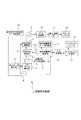
図1は、本実施の形態とされる音響再生装置の構成を示したブロック図である。
この図1において、音声データ再生部2は、例えば図示していない記録メディアに記録されている音声データを読み出し、読み出した音声データをデコードするといった再生処理を行うようにされる。First, the sound reproducing apparatus according to the present embodiment will be described with reference to FIGS.
FIG. 1 is a block diagram showing a configuration of a sound reproducing apparatus according to the present embodiment.
In FIG. 1, an audio
メタデータ解析部3は、音声データ再生部2を介して記録メディアに記録されているメタデータを取得するようにされる。そして、取得したメタデータを解析して記録メディアの音声データを再生するのに適した再生音場空間とするようにリスニングルームの音響特性を決定するようにされる。記録メディアにメタデータとして記録される再生音場空間の性質は図2のように示すことができる。The metadata analysis unit 3 acquires the metadata recorded on the recording medium via the audio
再生音場空間の性質はリバーブによって示される。リバーブは、図2(b)に示すように原音(直接音)と初期反射音、リバーブ本体の残響音によって示されることになる。
このため、再生音場空間の性質を示すパラメータとその尺度(定義)は、図2(a)のように示すことができる。The nature of the reproduced sound field space is indicated by reverb. As shown in FIG. 2B, the reverb is indicated by the original sound (direct sound), the initial reflected sound, and the reverberation sound of the reverb body.
For this reason, the parameters indicating the properties of the reproduced sound field space and their scales (definitions) can be shown as shown in FIG.
例えば、レートリバーブレンス(late reverberance)は直接音からリバーブ本体までの残響時間長により示され、例えばその数値は1.4〜2.8(sec)とされる。
ライブネス(liveness)は高音の残響時間長により示され、その数値は例えば1.5〜2.2(sec)とされる。
ソースプレゼンス(source presence)は直接音と初期反射音との比により示され、例えばその数値は−2〜2(dB)とされる。
ワームス(warmth)は低音の初期反射音と高音の初期反射音との比により示され、例えばその数値は1.2〜1.25(dB)とされる。
ルームプレゼンス(room presence)は残響音のレベルにより示され、例えばその数値は−0.5〜0.5(dB)とされる。
ランニングリバーブレンス(running reverberance)は初期反射音の残響時間長により示され、例えばその数値は1.8〜2.6(sec)とされる。
エンベロープメント(envelopment)は直接音に対する初期反射音の比率により示され、例えばその数値は0.1〜0.3(%)とされる。For example, the rate Reverb Reference (late reverbe rance) is indicated by the reverberation time length from the direct sound to reverb body, for example, the numerical value is set to 1.4 to 2.8 (sec).
Liveness is indicated by the reverberation time length of a high tone, and the numerical value is, for example, 1.5 to 2.2 (sec).
The source presence is indicated by the ratio of the direct sound and the initial reflected sound, and for example, the numerical value is −2 to 2 (dB).
Warmth is indicated by a ratio between a low-frequency initial reflection sound and a high-frequency initial reflection sound, and its numerical value is, for example, 1.2 to 1.25 (dB).
The room presence is indicated by the level of the reverberant sound, for example, the value is -0.5 to 0.5 (dB).
Running reverberation Reference (running reverbe rance) is indicated by the reverberation time length of the initial reflected sound, for example, the numerical value is set to 1.8 to 2.6 (sec).
The envelope is indicated by the ratio of the initial reflected sound to the direct sound. For example, the numerical value is 0.1 to 0.3 (%).
音響特性データ記憶部4は、例えばメモリにより構成され、メタデータ解析部3で解析した音響特性データを記憶するようにされる。 The acoustic characteristic data storage unit 4 is configured by a memory, for example, and stores acoustic characteristic data analyzed by the metadata analysis unit 3.
切替スイッチ5は、再生特性制御部6に供給する音声データに対応した音響特性データを選択するスイッチであり、音響特性データ記憶部4に一旦記憶した音響特性データ、またはメタデータ解析部3から出力される音響特性データの何れかを選択するようにされる。The changeover switch 5 is a switch for selecting acoustic characteristic datacorresponding to the audio data supplied to the reproduction
再生特性調整部7は、再生特性制御部6の制御に基づいて音声データ再生部2で再生された音声データに対する音響特性を調整するようにされる。
再生特性制御部6は、切替スイッチ5を介してメタデータ解析部3または音響特性データ記憶部4から入力される音響特性データと、切替スイッチ18を介して入力されるリスニングルームの室内音響特性データとに基づいて、再生特性調整部7の制御を行うようにされる。なお、リスニングルームの音響特性データの取得方法については後述する。The reproduction characteristic adjusting
The reproduction
切替スイッチ8は、室内音響特性解析部16に対して室内音響特性測定データ記憶部19の測定データ、または音声データ再生部2の音声データのいずれかを供給するためのスイッチとされる。 The
切替スイッチ9は、後段のD/A変換部10に対して、再生特性調整部7からの音声データ、または後述する音響特性測定データ記憶部19からの音響特性測定データの何れかを供給するためのスイッチとされる。 The
D/A変換部10は、切替スイッチ9を介して入力されるデジタル信号(データまたは音響特性測定データ)をアナログ信号(音声信号または音響特性測定信号)に変換して出力するようにされる。 The D /
電力増幅部11は、D/A変換部10からのアナログ信号を所定レベルまで増幅し、スピーカシステム12は、電力増幅部11で増幅した信号を可聴音として出力するようにされる。
マイクロフォンシステム13は、例えばリスニングルームの室内音響特性を測定するときに、所定のリスニングポイント(聴取位置)に配置され、その位置において音響を収音するようにされる。
マイクロフォン増幅部14は、マイクロフォンシステム13で収音して得られた収音信号を増幅して出力するようにされる。
A/D変換部15は、マイクロフォン増幅部14からのアナログ収音信号をデジタル収音信号に変換して出力するようにされる。For example, when measuring the room acoustic characteristics of a listening room, the
The
The A /
室内音響特性解析部16は、切り替えスイッチ8を介して入力される入力信号を基準信号として、A/D変換部15を介して入力される収音データの解析を行うことでリスニングルームの室内音響特性を得るようにされる。
室内音響特性データ記憶部17は、例えばメモリにより構成され、室内音響特性解析部16で得られた室内音響特性データを記憶するようにされる。The room acoustic
The room acoustic characteristic
切替スイッチ18は、再生特性制御部6に供給するリスニングルームの音響特性データを選択するスイッチであり、音響特性データとして、室内音響特性データ記憶部17に一旦記憶した音響特性データ、または、室内音響特性解析部16から直接出力される音響特性データの何れかを供給するようにされる。 The
室内音響特性測定データ記憶部19には、リスニングルームなどの室内音響特性を測定するための測定データが記憶されている。このような測定データは、M系列信号(Maximum Length Sequence)、TSP(Time Stretched Pulse)信号などが考えられる。 The room acoustic characteristic measurement
なお、このような音響再生装置1全体の制御や、切替スイッチ5,8,9,18の切り替え制御は、図示していないシステムコントローラによって行われている。 Note that such control of the entire
このように構成される音響再生装置1においては、記録メディアに記録されているメタデータから得られる音響特性と、実際のリスニングルームの室内音響特性に基づいて、音声データの音響特性の調整を行うようにしている。このため、音響再生装置1においては、音声データに対応する音響特性を取得する音響特性取得手段としてメタデータ解析部3が設けられていると共に、リスニングルームの室内音響特性を測定するための音響特性測定手段が設けられている。In the
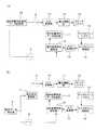
図3(a)(b)は、上記した音響再生装置1に設けられている音響特性測定手段の構成を示した図である。
図3(a)には、室内音響特性測定データ記憶部19を利用した音響特性測定手段の構成を示した図である。この場合、室内音響特性測定データ記憶部19からは、測定項目に適した音源データを選択して読み出す。そして、読み出した測定データは切替スイッチ9を介してD/A変換部10に伝送し、D/A変換部10でD/A変換した後、電力増幅部11で増幅し、増幅した測定信号をスピーカシステム12から出力するようにしている。FIGS. 3A and 3B are diagrams showing the configuration of the acoustic characteristic measuring means provided in the above-described
FIG. 3A is a diagram illustrating a configuration of an acoustic characteristic measuring unit using the room acoustic characteristic measurement
スピーカシステム12の出力音は、リスニングルームの所定の測定点に設置されたマイクロフォンシステム13のマイクロフォンにより収音するようにされる。
そして、マイクロフォンシステム13のマイクロフォンから出力される収音信号をマイクロフォン増幅部14で増幅し、増幅した収音信号をA/D変換部15でA/D変換した後、室内音響特性解析部16に伝送するようにされる。The output sound of the
Then, the sound collection signal output from the microphone of the
この場合、室内音響特性解析部16では、切替スイッチ8を介して室内音響特性測定データ記憶部19から入力される測定データを基準データとして収音データの解析を行うことで、リスニングルームの音響特性(伝達関数)を得るようにしている。
室内音響特性解析部16の解析結果は、室内音響特性データ記憶部17に記憶するようにしている。In this case, the room acoustic
The analysis result of the room acoustic
ここで、室内音響特性解析部16において、室内音響特性測定データ記憶部19の測定データを基準データとしてリスニングルームの伝達関数を得るようにしているのは以下のような理由による。 Here, the reason why the room acoustic
基本的には、スピーカシステム12から出力する測定音の信号をインパルス信号として、その応答をマイクロフォンシステム13で収音すれば、マイクロフォンシステム13の収音信号がリスニングルームの伝達関数となるが、この方法ではS/Nを上げることが困難とされる。このため、本実施の形態では、測定データとしてエネルギーが大きい信号を用い、室内音響特性解析部16において、A/D変換器15を介して入力される収音データ(応答信号)を切替スイッチ8を介して入力される測定データで割り算することでリスニングルームの伝達関数を算出するようにしている。 Basically, if the measurement sound signal output from the
また、非特許文献2によれば、等価両耳間距離(約30cm)で配置した2つの無指向性マイクロフォンの相関係数を解析することで、音場が自然な拡散性をもっているかを判断できるものとされる。したがって、例えば再生特性を幾通りか変化させ、そのときの聴取位置での相関係数を測定すれば、室内音響特性解析部16において自然な拡散音場に近い条件を室内音響特性データが得られることになる。
なお、室内音響特性測定データ記憶部19から発生させる室内音響特性の測定データは、DSP(Digital Signal Processor)などの演算手段によって、その都度生成するようにしても良い。Further, according to
The room acoustic characteristic measurement data generated from the room acoustic characteristic measurement
一方、図3(b)には、室内音響特性測定データ記憶部19を利用しない場合の音響特性測定手段の構成を示した図である。
この場合は、音声データ再生部2で再生された音声データを測定データとして用いるようにしている。つまり、音声データ再生部2で再生した音声データを、再生特性調整部7、切替スイッチ9を介してD/A変換部10に伝送し、D/A変換部10でD/A変換した後、電力増幅部11で増幅し、増幅した音声信号をスピーカシステム12から出力するようにしている。On the other hand, FIG. 3B is a diagram showing the configuration of the acoustic characteristic measurement means when the room acoustic characteristic measurement
In this case, the audio data reproduced by the audio
この場合も、スピーカシステム12の出力音は、マイクロフォンシステム13のマイクロフォンにより収音する。そして、マイクロフォンシステム13のマイクロフォンから出力される収音信号をマイクロフォン増幅部14で増幅し、増幅した収音信号をA/D変換部15でA/D変換した後、室内音響特性解析部16に伝送する。 Also in this case, the output sound of the
室内音響特性解析部16では、切替スイッチ8を介して音声データ再生部2から入力される音声データ等を利用して、測定測定項目に応じた解析を行うことで、再生音場空間であるリスニングルームの音響特性(伝達関数)を得るようにしている。
このような室内音響特性解析部16の解析結果は、室内音響特性データ記憶部17に記憶するようにしている。この場合も、収音データ(応答信号)を音声データ(入力信号)で割り算することで伝達関数が得られることになる。なお、室内音響特性データ記憶部17には、予め代表的なリスニングルームの室内音響特性を記憶させておくことも可能である。The room acoustic
The analysis result of the room acoustic
そして、このように構成される本実施の形態の音響再生装置1では、リスニングルームの室内音響特性の測定を行い、測定したリスニングルームの音響特性と、記録メディアに記録されているメタデータの音響特性に基づいて、再生特性調整部7において音声データ再生部2から再生される音声データの音響特性を調整するようにしている。
このようにすれば、本実施の形態の音響再生装置1において、リスニングルームの室内音響特性と、再生すべき音楽ソースの音声信号を録音したときの音響特性に応じて、音声信号を再生するときの音響特性の調整を行うことができる。
この結果、音響再生装置1において録音環境やジャンルが異なる音楽ソースを再生する場合でも、ユーザが音響特性の調整を行うことなく、自動的に音楽ソースに適した音響特性に調整して再生することが可能になる。In the
In this way, in the
As a result, even when a music source having a different recording environment or genre is played in the
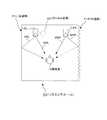
ここで、リスニングルームが音像に影響を与える音響特性について説明しておく。
音響特性に影響を与えるリスニングルームの構造としては、例えば音響空間の左右の非対称性がある。そのようなリスニングルームの一例を図4に示す。
この図4に示すリスニングルーム20は、聴取者Uの左壁面21Lに比べて右壁面21Rのほうが吸音性が高く、右壁面21Rからの反射音が殆ど無いものとされる。つまり、左壁面21Lと右壁面21Rでは反射の状態が大きく異なるものとされる。Here, the acoustic characteristics that the listening room affects the sound image will be described.
The listening room structure that affects the acoustic characteristics includes, for example, left-right asymmetry of the acoustic space. An example of such a listening room is shown in FIG.
In the
この場合、聴取者Uの左前方に配置されている左スピーカ12Lから聴取者Uに到達する音と、聴取者Uの右前方に配置されている右スピーカ12Rから聴取者Uに到達する音を比較すると、スピーカ12L,12Rからそれぞれ聴取者Uに到達する直接音SDL、SDRは、ほぼ同じとされるが、左右の壁面21L,21Rで反射した反射音SRL,SRRは大きく異なることになる。この結果、本来、左右スピーカ12L,12Rのほぼ中央位置に定位させるべきボーカルや主要楽器などの音像22が、反射音の大きい方向(この場合は左方向)にずれてしまったり、或いは特定方向からの響きだけが目立ってしまうなど、リスニングルーム20の音像に影響を与えることがある。 In this case, a sound that reaches the listener U from the
そこで、本実施の形態の音響再生装置1では、再生特性調整部7を図5に示すように構成して音声データの調整を行うようにしている。
この図5に示す再生特性調整部7は、擬似反射音付加回路23、チャネル間レベル差調整回路24により構成され、リスニングルーム20の右壁面21Rからの反射音がほとんど無い場合には、右スピーカ12Rから出力される音声データに対して擬似反射音付加回路23で擬似反射音データを付加した後、チャネル間レベル差調整回路24において左右チャネル間のレベル差を調整して出力するようにしている。
このように構成すると、リスニングルーム20の右壁面21Rからの反射音SRRが殆ど無い場合でも、右スピーカ12Rからの擬似反射音SRR1により、左右スピーカ12L,12Rのほぼ中央位置にボーカル等の音像22を定位させることができるようになる。Therefore, in the
The reproduction
With this configuration, even when there is almost no reflected sound SRR from the
また、再生特性調整部7に対して、破線で示すような擬似残響音データを付加する擬似残響音付加回路25を設け、右スピーカ12Rの再生音に対して、擬似残響音を付加すれば、より自然にボーカル等の音像22を定位させることができる。 Further, a pseudo reverberation
また再生特性調整部7は、図6に示すように構成することも可能である。
この図6に示す再生特性調整部7は、キャンセリングフィルタ51と擬似反射音付加回路23とにより構成され、キャンセリングフィルタ51において、リスニングルーム20の左右スピーカ12L,12Rからの再生音をキャンセルSCL,SCRしてから希望する反射音などの音響特性を付加するようにしている。つまり、スピーカ12L,12Rから聴取位置までの特性が平坦な周波数特性になるように逆特性をかけてから、疑似反射音付加回路23において希望する反射音の音響特性を付加するようにしている。The reproduction
The reproduction
このように構成すると、リスニングルーム20の右壁面21Rからの反射音SRRが殆ど無い場合でも、左スピーカ12Lからの擬似反射音SRL1と、右スピーカ12Rからの擬似反射音SRR1により、左右スピーカ12L,12Rのほぼ中央位置に拡がり感のあるボーカル等の音像22を定位させることができるようになる。 With this configuration, even if there is almost no reflected sound SRR from the
また、この場合も再生特性調整部7に対して、破線で示すような擬似残響音データを付加する擬似残響音付加回路25を設け、左右のスピーカ12L,12Rから出力される再生音に対して擬似残響音を付加すれば、さらにより自然に音像22を定位させることができるようになる。 Also in this case, a pseudo reverberation
ここで、上記したようなキャンセリングフィルタ51を図7を用いて説明しておく。
なお、図7では、再生音場空間69における左スピーカ67から聴取者Uの左耳ELに至る経路の頭部回折伝達関数をHLS、右スピーカ68から聴取者Uの右耳ERに至る経路の頭部回折伝達関数をHRSとする。また左スピーカ67から聴取者Uの右耳ERに至る経路の頭部回折伝達関数をHLO、右スピーカ68から聴取者Uの左耳ELに至る経路の頭部回折伝達関数をHROとする。Here, the canceling
In FIG. 7, the head diffraction transfer function of the path from the left speaker 67 to the left ear EL of the listener U in the reproduced
この図7に示すキャンセリングフィルタ51は、この図には示していないダミーヘッドマイクロフォンからの左収音信号SLinが左チャネル信号、右収音信号SRinが右チャネル信号として入力される。 In the canceling
左チャネル信号とされる左収音信号SLinは、加算器61とクロストークキャンセル部62に入力される。また、右チャネル信号とされる右収音信号SRinは、加算器64とクロストークキャンセル部63に入力される。 The left collected sound signal SLin, which is the left channel signal, is input to the
クロストークキャンセル部62,63は、それぞれ左スピーカ67から聴取者Uの右耳ERへのクロストークトーク成分と、右スピーカ68から聴取者Uの左耳ELへのクロストークトーク成分をキャンセルするためのフィルタとされる。 The crosstalk cancellation units 62 and 63 cancel the crosstalk talk component from the left speaker 67 to the right ear ER of the listener U and the crosstalk talk component from the right speaker 68 to the left ear EL of the listener U, respectively. It is considered as a filter.
この場合、クロストークキャンセル部62の伝達特性CRは−HRO/HRSと示される。またクロストークキャンセル部63の伝達特性CLは−HLO/HLSと示される。
そして、このようなクロストークキャンセル部62を通過した左収音信号SLinがキャンセル信号として加算器64に入力される。またクロストークキャンセル部63を通過した右収音信号SRinがキャンセル信号が加算器61に入力される。In this case, the transfer characteristic CR of the crosstalk cancel unit 62 is indicated as -HRO / HRS. The transfer characteristic CL of the crosstalk canceling unit 63 is indicated as -HLO / HLS.
Then, the left collected sound signal SLin that has passed through the crosstalk canceling unit 62 is input to the adder 64 as a cancel signal. Further, a cancel signal is input to the
加算器61は、入力される左収音信号SLinと、クロストークキャンセル部63からのキャンセル信号を加算して出力する。このような加算器61の出力は補正ブロック部65に供給される。
加算器64は、入力される右収音信号SRinとクロストークキャンセル部62からのキャンセル信号を加算して補正ブロック部66に供給するようにされる。The
The adder 64 adds the input right sound pickup signal SRin and the cancel signal from the crosstalk cancel unit 62 and supplies the sum to the correction block unit 66.
補正ブロック部65は、左チャネルについて左スピーカ67を含む再生系の補正を行うためのブロック部であり、クロストークキャンセル部63により生じる特性の変化を補正するための補正部65aと、スピーカ特性を補正するスピーカ補正部65bによって構成される。このような補正部65aの伝達特性は1/(1−CL・CR)と示される。また補正部65bの伝達特性は1/HLSと示されることになる。このような補正ブロック部65の出力は、キャンセリングフィルタ60から左収音信号SLoutとして出力される。 The correction block unit 65 is a block unit for correcting a reproduction system including the left speaker 67 for the left channel. The
また補正ブロック部66は、右チャネルについて右スピーカ68を含む再生系の補正を行うためのブロック部であり、クロストークキャンセル部62により生じる特性の変化を補正するための補正部66aと、スピーカ特性を補正するスピーカ補正部66bによって構成される。このような補正部66aの伝達特性は1/(1−CL・CR)と示される。また補正部66bの伝達特性は1/HRSと示されることになる。このような補正ブロック部66の出力は、キャンセリングフィルタ60から右収音信号SRoutとして出力される。 The correction block unit 66 is a block unit for correcting a reproduction system including the right speaker 68 for the right channel, and a
そして、このようなキャンセリングフィルタ60から出力される左収音信号SLoutを再生音場空間69の左スピーカ67に、右収音信号SRoutを再生音場空間69の右スピーカ68に入力する。すると、再生音場空間の聴取者Uの左耳ELには、キャンセリングフィルタ60に入力した左収音信号SLinに対応した左耳音だけを再生することができる。また、聴取者Uの右耳ERには、同じくキャンセリングフィルタ60に入力した右収音信号SRinに対応した右耳音だけを再生することができる。 Then, the left sound collection signal SLout output from the canceling filter 60 is input to the left speaker 67 of the reproduction
ところで、上記した本実施の形態の音響再生装置1では、記録メディアの音声データと共に、その音声データが再生されるべき目標となる空間の性質を示すメタデータが記録されているものとして説明したが、そのようなメタデータは必ずしも記録メディアに記録しておく必要はない。
例えば、記録メディアにコンテンツ識別コードを記録し、そのコンテンツ識別コードに対応するメタデータがネットワーク上のデータベースなどに記録しておくことも可能である。By the way, although the
For example, it is possible to record a content identification code on a recording medium and record metadata corresponding to the content identification code in a database on the network.
そこで、次に、本実施の形態の音響再生装置の他の構成として、記録メディアに記録されているコンテンツ識別コードに対応するメタデータがネットワーク上のデータベースなどに記録されている場合に好適な音響再生装置について説明する。 Therefore, next, as another configuration of the sound reproducing device of the present embodiment, sound suitable for a case where metadata corresponding to the content identification code recorded on the recording medium is recorded in a database on a network or the like. The playback device will be described.
図8は、そのような音響再生装置の構成を示したブロック図である。
なお、図1に示した音響再生装置1と同一部位には同一番号を付して説明は省略する。
この図8において、コンテンツ識別コード検出部31は、音声データ再生部2から出力される音声データから記録メディアに記録されているコンテンツ識別コードを検出するようにされる。FIG. 8 is a block diagram showing the configuration of such a sound reproducing device.
In addition, the same number is attached | subjected to the same site | part as the
In FIG. 8, the content
データベース検索部32は、コンテンツ識別コード検出部31において検出されたコンテンツ識別コードに基づいて、データベースからコンテンツ識別コードに対応するメタデータを読み出すようにされる。
例えば、データベース検索部32は、コンテンツ識別コードが音響再生装置30内のデータベース記憶装置部33に既にメタデータとともに記憶されている場合は、データベース記憶装置部33から対応するメタデータを読み出すようにされる。The
For example, the
一方、データベース記憶装置部33に未だ記憶されていない場合には、ネットワークアクセス部34を制御して、ネットワーク35上のデータベースからコンテンツ識別コードに対応するメタデータを読み出し、メタデータをコンテンツ識別コードとともにデータベース記憶装置部33に記憶するようにされる。 On the other hand, if not yet stored in the
音声データ解析部36は、データベース検索部32によりデータベースから検索したメタデータを解析して記録メディアの音声データを再生するのに適したリスニングルームの音響特性を決定するようにされる。 The audio
このような音響再生装置30においても、リスニングルーム20の室内音響特性と、記録メディアに記録されている音声データに対応したメタデータに基づいて、再生した音声データに対する音響特性を調整することができるので、上記同様、録音環境やジャンルが異なる音楽ソースをリスニングルームで再生する場合でも、自動的に音楽ソースに適した音響特性に調整して再生することが可能になる。In such a sound reproducing device 30, it can be adjusted and the indoor acoustic characteristics of the
なお、記録メディアに記録されている音声データなどを識別するためのコンテンツ識別コードは、コンテンツを識別するために記録されたものである必要はなく、例えば、コンパクトディスクのTOCデータや楽曲信号データの一部分のように、同じ数値の組み合わせが存在する確率が非常に小さいものをコンテンツ識別コードとして用いることも可能である。 Note that the content identification code for identifying audio data or the like recorded on the recording medium does not have to be recorded for identifying the content. For example, the TOC data of the compact disc or the music signal data It is also possible to use a content identification code that has a very low probability of having the same combination of numerical values, such as a part.
図9は、本実施の形態とされる音響再生装置のさらに他の構成を示したブロック図である。なお、図1及び図8に示した音響再生装置と同一部位には同一番号を付して説明は省略する。
この図9に示す音響再生装置40では、音声データ解析部36において、音声データ再生部2で再生した音声データの性質及び音声データが収録された音響空間、または、音声データが演奏されるであろう仮想音響空間の室内音響特性についての解析を行うようにしている。FIG. 9 is a block diagram showing still another configuration of the sound reproducing device according to the present embodiment. In addition, the same number is attached | subjected to the same site | part as the sound reproduction apparatus shown in FIG.1 and FIG.8, and description is abbreviate | omitted.
In the sound reproducing device 40 shown in FIG. 9, the sound
例えば、音声信号の自己相関関数の形状やケプストラムの形状から反射音の含まれるタイミングやその大きさを解析し、チャネル間の相互相関関数から音像の拡がりなどの解析を行うようにしている。
このとき、音声データ解析部36には、音声データの解析を行うときに周波数帯域に分けて反射音の構造を解析できるように帯域分割フィルタ機能を設けることが好ましい。For example, the timing and magnitude of the reflected sound are analyzed from the shape of the autocorrelation function of the audio signal and the shape of the cepstrum, and analysis such as sound image spread is performed from the cross-correlation function between channels.
At this time, it is preferable that the audio
また、音声データ解析部36の解析結果は、例えばコンテンツ識別コードごとに音声特性データ記憶部4に記憶しておき、コンテンツが選ばれるごとに呼び出しても良い。 The analysis result of the audio
このような音響再生装置40においても、リスニングルーム20の室内音響特性と、記録メディアに記録されている音声データから得た音響特性に基づいて、再生した音声データに対する音響特性を調整することができるので、上記同様、録音環境やジャンルが異なる音楽ソースをリスニングルームで再生する場合でも、自動的に音楽ソースに適した音響特性に調整して再生することが可能になる。In such a sound reproducing device 40, a room acoustic characteristic of the
なお、これまで説明した音響再生装置の構成はあくまでも一例であり、記録メディアから再生すべき再生データに対する音響特性と、リスニングルームの室内音響特性とに基づいて、音響特性の調整を行うような音響再生装置であれば、何れの構成のものでも適用可能である。Note that the configuration of the sound reproduction device described so far is merely an example, and the sound characteristics are adjusted based on the sound characteristicsfor the reproduction data to be reproduced from the recording medium and the room sound characteristics of the listening room. Any playback device can be used.
また、本実施の形態では、記録メディアが光ディスクとして説明したが、これはあくまでも一例であり、例えばブルーレイ(Blu-ray)方式のディスク、CD(Compact Disc)方式のディスク、ミニディスク(Mini Disc)、HDD(ハードディスクドライブ)、或いはフラッシュメモリなどのメモリカードなど各種考えられるものである。Further, in the present embodiment, the recording medium is described as an optical disk, which is only an example, for example, a Blu-ray (Blu-r ay) system of the disc, CD (Compact Disc) system of the disc, a mini disc (Mini Disc ) Various types of memory cards such as HDD (Hard Disk Drive) or flash memory.
1 30 40 音響再生装置、2 音声データ再生部、3 メタデータ解析部、4 音響特性データ記憶部、5 8 9 18 切替スイッチ、6 再生特性制御部、7 再生特性調整部、10 D/A変換部、11 電力増幅部、12 スピーカシステム、13 マイクロフォンシステム、14 マイクロフォン増幅部、15 A/D変換部、16 室内音響特性解析部、17 室内音響特性記憶部、19 室内音響特性測定データ記憶部、20 リスニングルーム、23 擬似反射音付加回路、24 チャネル間レベル差調整回路、25 擬似残響音付加回路、31 コンテンツ識別コード検出部、32 データベース検索部、33 データベース記憶装置部、34 ネットワークアクセス部、35 ネットワーク、36 音声データ解析部、51 キャンセリングフィルタ
1 30 40 sound reproduction device, 2 audio data reproduction unit, 3 metadata analysis unit, 4 acoustic characteristic data storage unit, 5 8 9 18 changeover switch, 6 reproduction characteristic control unit, 7 reproduction characteristic adjustment unit, 10 D /
Claims (7)
Translated fromJapanese上記音声データの音響特性を取得する音響特性取得手段と、
再生音場空間の室内音響特性を測定する音響特性測定手段と、
上記音響特性測定手段により測定した室内音響特性と、上記音響特性取得手段により取得した上記音声データの音響特性とに基づいて、上記音声データを再生するときの音響特性の調整を行う音響特性調整手段と、
を備えることを特徴とする音響再生装置。Audio data reproducing means for reproducing audio data;
Acoustic characteristic acquisition means for acquiring acoustic characteristics of the voice data;
Acoustic characteristic measuring means for measuring room acoustic characteristics of the reproduction sound field space;
Acoustic characteristic adjusting means for adjusting the acoustic characteristics when reproducing the audio data based on the room acoustic characteristics measured by the acoustic characteristic measuring means and the acoustic characteristics of the audio data acquired by the acoustic characteristic acquiring means When,
A sound reproducing device comprising:
上記再生音場空間に対して音響測定音を出力する音響測定音出力手段と、
上記音響測定音に基づいて、上記再生音場空間の音響特性を算出する室内音響特性算出手段と、
を備えることを特徴とする請求項2に記載の音響再生装置。The acoustic characteristic measuring means includes
Acoustic measurement sound output means for outputting acoustic measurement sound to the reproduction sound field space;
A room acoustic characteristic calculation means for calculating an acoustic characteristic of the reproduction sound field space based on the acoustic measurement sound;
The sound reproducing device according to claim 2, comprising:
上記再生音場空間に対して上記音声データ再生手段で再生した再生音に基づいて、上記再生音場空間の音響特性を算出する室内音響特性算出手段により構成されることを特徴とする請求項2に記載の音響再生装置。The acoustic characteristic measuring means includes
3. The room acoustic characteristic calculating means for calculating the acoustic characteristics of the reproduced sound field space based on the reproduced sound reproduced by the audio data reproducing means with respect to the reproduced sound field space. The sound reproducing device described in 1.
上記音声データの再生すべき音響特性データを上記音声データが記録されている記録メディアから取得することを特徴とする請求項2に記載の音響再生装置。The acoustic characteristic acquisition means is
The sound reproduction device according to claim 2, wherein the sound characteristic data to be reproduced of the sound data is obtained from a recording medium on which the sound data is recorded.
上記音声データから再生すべき音響特性データをネットワークを介して取得することを特徴とする請求項2に記載の音響再生装置。The acoustic characteristic acquisition means is
The sound reproduction apparatus according to claim 2, wherein the sound characteristic data to be reproduced is acquired from the sound data via a network.
上記音声データから再生すべき音響特性データを上記音声データから取得することを特徴とする請求項2に記載の音響再生装置。
The acoustic characteristic acquisition means is
The sound reproduction device according to claim 2, wherein sound characteristic data to be reproduced from the sound data is acquired from the sound data.
Priority Applications (5)
| Application Number | Priority Date | Filing Date | Title |
|---|---|---|---|
| JP2004057814AJP2005252467A (en) | 2004-03-02 | 2004-03-02 | Sound reproduction method, sound reproducing device and recording medium |
| EP05250924AEP1571884A3 (en) | 2004-03-02 | 2005-02-17 | Sound reproducing method and apparatus |
| KR1020050016491AKR20060043240A (en) | 2004-03-02 | 2005-02-28 | Sound playback methods and sound playback devices and recording media |
| US11/068,709US20050195984A1 (en) | 2004-03-02 | 2005-03-01 | Sound reproducing method and apparatus |
| CN2005100529482ACN1664921A (en) | 2004-03-02 | 2005-03-02 | Sound reproducing method and apparatus |
Applications Claiming Priority (1)
| Application Number | Priority Date | Filing Date | Title |
|---|---|---|---|
| JP2004057814AJP2005252467A (en) | 2004-03-02 | 2004-03-02 | Sound reproduction method, sound reproducing device and recording medium |
Related Child Applications (1)
| Application Number | Title | Priority Date | Filing Date |
|---|---|---|---|
| JP2008087940ADivisionJP2008233920A (en) | 2008-03-28 | 2008-03-28 | Sound reproducing device and sound reproducing method |
Publications (1)
| Publication Number | Publication Date |
|---|---|
| JP2005252467Atrue JP2005252467A (en) | 2005-09-15 |
Family
ID=34747627
Family Applications (1)
| Application Number | Title | Priority Date | Filing Date |
|---|---|---|---|
| JP2004057814APendingJP2005252467A (en) | 2004-03-02 | 2004-03-02 | Sound reproduction method, sound reproducing device and recording medium |
Country Status (5)
| Country | Link |
|---|---|
| US (1) | US20050195984A1 (en) |
| EP (1) | EP1571884A3 (en) |
| JP (1) | JP2005252467A (en) |
| KR (1) | KR20060043240A (en) |
| CN (1) | CN1664921A (en) |
Cited By (10)
| Publication number | Priority date | Publication date | Assignee | Title |
|---|---|---|---|---|
| JP2007214726A (en)* | 2006-02-08 | 2007-08-23 | Sony Corp | Audio signal output apparatus and sound leakage reducing method |
| JP2009531722A (en)* | 2006-09-20 | 2009-09-03 | ハーマン インターナショナル インダストリーズ インコーポレイテッド | Method and apparatus for extracting and modifying echo content of an input signal |
| JP2009261022A (en)* | 2009-08-10 | 2009-11-05 | Yamaha Corp | Sound field control apparatus |
| JP2010259008A (en)* | 2009-04-28 | 2010-11-11 | Toshiba Corp | Signal processing apparatus, acoustic apparatus, and signal processing method |
| JP2011217068A (en)* | 2010-03-31 | 2011-10-27 | Yamaha Corp | Sound field controller |
| US8199921B2 (en) | 2006-04-28 | 2012-06-12 | Yamaha Corporation | Sound field controlling device |
| JP2014026241A (en)* | 2012-07-30 | 2014-02-06 | Yamaha Corp | Reverberation time analyzer |
| JP2015084584A (en)* | 2014-12-26 | 2015-04-30 | ヤマハ株式会社 | Sound field control device |
| JP2020166052A (en)* | 2019-03-28 | 2020-10-08 | 株式会社デンソーテン | Sound equipment and sound control method |
| JP2022054933A (en)* | 2020-09-28 | 2022-04-07 | 株式会社デンソーテン | Acoustic device and acoustic control method |
Families Citing this family (18)
| Publication number | Priority date | Publication date | Assignee | Title |
|---|---|---|---|---|
| JP4222276B2 (en) | 2004-08-27 | 2009-02-12 | ソニー株式会社 | Playback system |
| US8180067B2 (en) | 2006-04-28 | 2012-05-15 | Harman International Industries, Incorporated | System for selectively extracting components of an audio input signal |
| KR100873639B1 (en)* | 2007-01-23 | 2008-12-12 | 삼성전자주식회사 | Apparatus and method for externalizing sound images output from headphones. |
| KR100902874B1 (en)* | 2007-06-26 | 2009-06-16 | 버츄얼빌더스 주식회사 | Spatial acoustic analyzer and its method based on material style |
| US8675882B2 (en)* | 2008-01-21 | 2014-03-18 | Panasonic Corporation | Sound signal processing device and method |
| JP4623124B2 (en)* | 2008-04-07 | 2011-02-02 | ソニー株式会社 | Music playback device, music playback method, and music playback program |
| JP4640463B2 (en)* | 2008-07-11 | 2011-03-02 | ソニー株式会社 | Playback apparatus, display method, and display program |
| US9372251B2 (en) | 2009-10-05 | 2016-06-21 | Harman International Industries, Incorporated | System for spatial extraction of audio signals |
| US8706278B2 (en)* | 2012-02-15 | 2014-04-22 | GM Global Technology Operations LLC | Non-bussed vehicle amplifier diagnostics |
| JP2013198065A (en)* | 2012-03-22 | 2013-09-30 | Denso Corp | Sound presentation device |
| EP2809088B1 (en)* | 2013-05-30 | 2017-12-13 | Barco N.V. | Audio reproduction system and method for reproducing audio data of at least one audio object |
| JP6138015B2 (en)* | 2013-10-01 | 2017-05-31 | クラリオン株式会社 | Sound field measuring device, sound field measuring method, and sound field measuring program |
| CN108141693B (en)* | 2015-10-09 | 2021-10-29 | 索尼公司 | Signal processing apparatus, signal processing method, and computer-readable storage medium |
| DE102017113275B4 (en)* | 2017-06-16 | 2025-10-09 | Burmester Audiosysteme Gmbh | Method for reproducing audio material in a vehicle, computer program product and vehicle |
| US10897680B2 (en) | 2017-10-04 | 2021-01-19 | Google Llc | Orientation-based device interface |
| CN110663173B (en)* | 2017-10-04 | 2023-09-19 | 谷歌有限责任公司 | Method and system for automatically equalizing audio output based on room characteristics |
| WO2021010884A1 (en)* | 2019-07-18 | 2021-01-21 | Dirac Research Ab | Intelligent audio control platform |
| CN114286278B (en)* | 2021-12-27 | 2024-03-15 | 北京百度网讯科技有限公司 | Audio data processing method and device, electronic equipment and storage medium |
Family Cites Families (11)
| Publication number | Priority date | Publication date | Assignee | Title |
|---|---|---|---|---|
| DE3142462A1 (en)* | 1980-10-28 | 1982-05-27 | Hans-Peter 7000 Stuttgart Pfeiffer | Loudspeaker device |
| JPS63183495A (en)* | 1987-01-27 | 1988-07-28 | ヤマハ株式会社 | Sound field controller |
| JPS644200A (en)* | 1987-06-26 | 1989-01-09 | Nissan Motor | Sound field improving device |
| JP2617990B2 (en)* | 1988-06-03 | 1997-06-11 | 富士通テン株式会社 | Audio signal recording medium and reproducing apparatus therefor |
| US5146507A (en)* | 1989-02-23 | 1992-09-08 | Yamaha Corporation | Audio reproduction characteristics control device |
| US6760451B1 (en)* | 1993-08-03 | 2004-07-06 | Peter Graham Craven | Compensating filters |
| US7333863B1 (en)* | 1997-05-05 | 2008-02-19 | Warner Music Group, Inc. | Recording and playback control system |
| JP2003091290A (en)* | 2001-09-18 | 2003-03-28 | Clarion Co Ltd | Communication type in-cabin sound filed control system, data distribution center, and on-vehicle acoustic system |
| JP4059478B2 (en)* | 2002-02-28 | 2008-03-12 | パイオニア株式会社 | Sound field control method and sound field control system |
| US20040114771A1 (en)* | 2002-12-12 | 2004-06-17 | Mitchell Vaughan | Multimedia system with pre-stored equalization sets for multiple vehicle environments |
| JP4222276B2 (en)* | 2004-08-27 | 2009-02-12 | ソニー株式会社 | Playback system |
- 2004
- 2004-03-02JPJP2004057814Apatent/JP2005252467A/enactivePending
- 2005
- 2005-02-17EPEP05250924Apatent/EP1571884A3/ennot_activeWithdrawn
- 2005-02-28KRKR1020050016491Apatent/KR20060043240A/ennot_activeWithdrawn
- 2005-03-01USUS11/068,709patent/US20050195984A1/ennot_activeAbandoned
- 2005-03-02CNCN2005100529482Apatent/CN1664921A/enactivePending
Cited By (13)
| Publication number | Priority date | Publication date | Assignee | Title |
|---|---|---|---|---|
| JP2007214726A (en)* | 2006-02-08 | 2007-08-23 | Sony Corp | Audio signal output apparatus and sound leakage reducing method |
| US8199921B2 (en) | 2006-04-28 | 2012-06-12 | Yamaha Corporation | Sound field controlling device |
| JP2009531722A (en)* | 2006-09-20 | 2009-09-03 | ハーマン インターナショナル インダストリーズ インコーポレイテッド | Method and apparatus for extracting and modifying echo content of an input signal |
| JP2010259008A (en)* | 2009-04-28 | 2010-11-11 | Toshiba Corp | Signal processing apparatus, acoustic apparatus, and signal processing method |
| JP2009261022A (en)* | 2009-08-10 | 2009-11-05 | Yamaha Corp | Sound field control apparatus |
| US8724821B2 (en) | 2010-03-31 | 2014-05-13 | Yamaha Corporation | Sound field controller |
| JP2011217068A (en)* | 2010-03-31 | 2011-10-27 | Yamaha Corp | Sound field controller |
| JP2014026241A (en)* | 2012-07-30 | 2014-02-06 | Yamaha Corp | Reverberation time analyzer |
| JP2015084584A (en)* | 2014-12-26 | 2015-04-30 | ヤマハ株式会社 | Sound field control device |
| JP2020166052A (en)* | 2019-03-28 | 2020-10-08 | 株式会社デンソーテン | Sound equipment and sound control method |
| JP7149216B2 (en) | 2019-03-28 | 2022-10-06 | 株式会社デンソーテン | Acoustic device and acoustic control method |
| JP2022054933A (en)* | 2020-09-28 | 2022-04-07 | 株式会社デンソーテン | Acoustic device and acoustic control method |
| JP7487060B2 (en) | 2020-09-28 | 2024-05-20 | 株式会社デンソーテン | Audio device and audio control method |
Also Published As
| Publication number | Publication date |
|---|---|
| US20050195984A1 (en) | 2005-09-08 |
| KR20060043240A (en) | 2006-05-15 |
| EP1571884A3 (en) | 2008-08-20 |
| CN1664921A (en) | 2005-09-07 |
| EP1571884A2 (en) | 2005-09-07 |
Similar Documents
| Publication | Publication Date | Title |
|---|---|---|
| JP2005252467A (en) | Sound reproduction method, sound reproducing device and recording medium | |
| JP4222276B2 (en) | Playback system | |
| JP4059478B2 (en) | Sound field control method and sound field control system | |
| US7379552B2 (en) | Smart speakers | |
| JP3584800B2 (en) | Sound field reproduction method and apparatus | |
| JP2003255955A5 (en) | ||
| JP4819823B2 (en) | Acoustic system driving apparatus, driving method, and acoustic system | |
| JP5611970B2 (en) | Converter and method for converting audio signals | |
| CN106664497A (en) | Audio reproduction systems and methods | |
| US7783054B2 (en) | System for auralizing a loudspeaker in a monitoring room for any type of input signals | |
| JP4167286B2 (en) | Reverberation adjustment device, reverberation correction method, and sound reproduction system | |
| JP6701824B2 (en) | Measuring device, filter generating device, measuring method, and filter generating method | |
| JP3902065B2 (en) | Surround headphone output signal generator | |
| JP2001509976A (en) | Recording and playback two-channel system for providing holophonic reproduction of sound | |
| JP2005157278A (en) | Apparatus, method, and program for creating all-around acoustic field | |
| EP1458218A2 (en) | Sound field control system and method | |
| JP4791613B2 (en) | Audio adjustment device | |
| JP2008282042A (en) | Reproduction device | |
| Shimokura et al. | Listening level of music through headphones in train car noise environments | |
| JP2012168367A (en) | Reproducer, method thereof, and program | |
| US6925426B1 (en) | Process for high fidelity sound recording and reproduction of musical sound | |
| JP2010136236A (en) | Audio signal processing apparatus and method, and program | |
| JP2008233920A (en) | Sound reproducing device and sound reproducing method | |
| JP3957819B2 (en) | Sound field correction method and sound field correction apparatus | |
| JP2022054933A (en) | Acoustic device and acoustic control method |
Legal Events
| Date | Code | Title | Description |
|---|---|---|---|
| A131 | Notification of reasons for refusal | Free format text:JAPANESE INTERMEDIATE CODE: A131 Effective date:20071016 | |
| A521 | Request for written amendment filed | Free format text:JAPANESE INTERMEDIATE CODE: A523 Effective date:20071214 | |
| A131 | Notification of reasons for refusal | Free format text:JAPANESE INTERMEDIATE CODE: A131 Effective date:20080129 | |
| A02 | Decision of refusal | Free format text:JAPANESE INTERMEDIATE CODE: A02 Effective date:20080527 |