JP2005250220A - Polymer film, polarizer, production method thereof, polarizing plate, optical film, and image display device - Google Patents
Polymer film, polarizer, production method thereof, polarizing plate, optical film, and image display deviceDownload PDFInfo
- Publication number
- JP2005250220A JP2005250220AJP2004062010AJP2004062010AJP2005250220AJP 2005250220 AJP2005250220 AJP 2005250220AJP 2004062010 AJP2004062010 AJP 2004062010AJP 2004062010 AJP2004062010 AJP 2004062010AJP 2005250220 AJP2005250220 AJP 2005250220A
- Authority
- JP
- Japan
- Prior art keywords
- film
- fine particles
- polymer
- metal fine
- dispersed
- Prior art date
- Legal status (The legal status is an assumption and is not a legal conclusion. Google has not performed a legal analysis and makes no representation as to the accuracy of the status listed.)
- Pending
Links
Images


Landscapes
- Liquid Crystal (AREA)
- Electroluminescent Light Sources (AREA)
- Polarising Elements (AREA)
Abstract
Translated fromJapaneseDescription
Translated fromJapanese本発明は、高分子フィルムおよび当該フィルムを用いた偏光子、ならびにそれらの製造方法に関する。また本発明は当該偏光子を用いた偏光板、光学フィルムに関する。さらには当該偏光子、偏光板、光学フィルムを用いた液晶表示装置、有機EL表示装置、PDP等の画像表示装置に関する。 The present invention relates to a polymer film, a polarizer using the film, and a production method thereof. The present invention also relates to a polarizing plate and an optical film using the polarizer. Furthermore, the present invention relates to an image display device such as a liquid crystal display device, an organic EL display device, and a PDP using the polarizer, polarizing plate, and optical film.
液晶表示装置等に代表される次世代の画像表示装置には、偏光子(偏光板)が用いられている。近年では、画像表示装置の大面積化、多様化に伴い、偏光子の需要も拡大しており、かつ品質向上・耐久性への要求は大きくなっている。前記画像表示装置はテレビ、パソコン等に用いられる他、各種の用途で用いられる。特に、携帯電話、PDAなどの屋外での過酷な環境下での使用を想定した液晶表示装置や、車載用ナビゲーション、液晶プロジェクタ用の液晶表示装置等には非常に高い耐久性が要求される。 A next-generation image display device represented by a liquid crystal display device or the like uses a polarizer (polarizing plate). In recent years, with the increase in area and diversification of image display devices, the demand for polarizers has also increased, and the demand for quality improvement and durability has increased. The image display device is used in various applications in addition to being used in televisions, personal computers, and the like. In particular, a liquid crystal display device that is assumed to be used in a harsh environment outdoors such as a mobile phone and a PDA, a vehicle-mounted navigation, a liquid crystal display device for a liquid crystal projector, and the like are required to have extremely high durability.
従来、画像表示装置用の偏光子としては、主に延伸したポリビニルアルコールフィルムにヨウ素や二色性染料で染色した構造のものが用いられている。ヨウ素系偏光子は、非晶性であるヨウ素を混入した水溶液によりフィルムを染色したのち、延伸処理を施すことによって得られ、可視光に対する高い偏光性を有し、大型偏光子の作製が可能である。しかし、ヨウ素系偏光子は耐久性に乏しく、ヨウ素が高温で昇華したり、錯体構造が変化したりするために偏光性能を維持することが難しい。一方、二色性染料を用いた染料系偏光子は、ヨウ素系偏光子に比べて耐久性はよいものの、染料の二色比が十分でないことや耐候性などに劣ることなどから、一部の用途を除いては広く採用はされていない。 Conventionally, as a polarizer for an image display device, one having a structure in which a stretched polyvinyl alcohol film is dyed with iodine or a dichroic dye is used. An iodine-based polarizer is obtained by dyeing a film with an aqueous solution mixed with amorphous iodine, followed by stretching treatment, and has a high polarization property for visible light, making it possible to produce a large polarizer. is there. However, iodine-based polarizers have poor durability, and it is difficult to maintain polarization performance because iodine sublimes at high temperatures and the complex structure changes. On the other hand, although dye-based polarizers using dichroic dyes have better durability than iodine-based polarizers, some of the dye dichroic ratios are not sufficient and weather resistance is inferior. It is not widely adopted except for its use.
また高温での耐久性の要求される光通信、光記録再生装置、光導波路用ビームスプリッターなどの光デバイス分野で用いられる偏向器として、ガラス中に金属微粒子を分散した偏光器が知られている。現在、金属微粒子を使用し偏光機能を制御する素子としては、グリッド偏光器が一般的に知られている。たとえば、誘電体基板上に金属膜を形成し、基板と金属膜とを延伸することにより異方的な形状を有する金属部分をもつ構造を形成したワイヤグリッド型の偏光光学素子が提案されている(特許文献1参照)。しかし、前記金属膜は真空蒸着法等により形成するため、高い熱プロセスが必要であり、量産に適していない。 Also, as a deflector used in the field of optical devices such as optical communication, optical recording / reproducing apparatus, and optical waveguide beam splitter that require durability at high temperatures, a polarizer in which metal fine particles are dispersed in glass is known. . Currently, a grid polarizer is generally known as an element that uses metal fine particles to control the polarization function. For example, a wire grid type polarization optical element has been proposed in which a metal film is formed on a dielectric substrate, and a structure having a metal portion having an anisotropic shape is formed by stretching the substrate and the metal film. (See Patent Document 1). However, since the metal film is formed by a vacuum vapor deposition method or the like, a high thermal process is required and it is not suitable for mass production.
一方、金属微粒子の吸収光学効果を利用した偏光素子としては、誘電体基板上に形状其方性を有する金属微粒子を分散し、形状異方性に伴う光吸収異方性を利用した偏光素子が提案されている(特許文献2、特許文献3参照)。しかし、これらの偏光素子は、金属微粒子を分散させる層をゾルゲル法により形成しているため、柔軟性が十分ではない。 On the other hand, as a polarizing element utilizing the absorption optical effect of metal fine particles, a polarizing element utilizing light absorption anisotropy associated with shape anisotropy is obtained by dispersing metal fine particles having shape isotropy on a dielectric substrate. It has been proposed (see Patent Document 2 and Patent Document 3). However, these polarizing elements are not sufficiently flexible because a layer in which metal fine particles are dispersed is formed by a sol-gel method.
また、金属微粒子をポリイミド中に分散し、一軸延伸処理した偏光性フィルムが提案されている(特許文献4参照)。しかし、かかる偏光性フィルムは、二色性が十分ではない。
上記課題を解決するため、本出願人は特願2003−329436号、特願2003−186684号を出願した。当該出願に係わる発明によれば、透明性のポリマー等をマトリクスとし、その中に金属微粒子を分散し、延伸することにより簡易なプロセスで、透明性、耐久性の良好な偏光子を得ることができている。当該発明に記載の偏光子は、金属微粒子内部の電子振動によるプラズモン吸収を用いている。 In order to solve the above problems, the present applicant has filed Japanese Patent Application Nos. 2003-329436 and 2003-186684. According to the invention relating to the application, a transparent polymer or the like can be used as a matrix, and metal fine particles can be dispersed therein and stretched to obtain a polarizer having good transparency and durability by a simple process. is made of. The polarizer described in the invention uses plasmon absorption due to electronic vibration inside the metal fine particles.
金属微粒子の光学特性については、「Near Field Spectral Analysis of Metallic Beads(Topics Appl.Phys.81,97−122)において述べられている。すなわち、当該文献には、金属微粒子の吸収は、マトリクスの屈折率及び金属微粒子の粒径に依存するほかに、一定の距離内では、粒子内の双極子運動は粒子間の距離に依存した相互作用により偏光依存性を持つことが記載されている。したがって、複屈折性ポリマー中において粒子間の距離を制御することができれば、偏光の入射方向による吸収波長帯域の差は大きくなり、より高い二色比を持つ偏光子を得ることができる可能性がある。 The optical properties of the metal fine particles are described in “Near Field Spectral Analysis of Metallic Beads (Topics Appl. Phys. 81, 97-122). That is, in this document, the absorption of metal fine particles is the refraction of the matrix. Besides depending on the rate and the particle size of the metal microparticles, it is described that within a certain distance, the dipole motion within the particle is polarization dependent due to the interaction depending on the distance between the particles. If the distance between particles in the birefringent polymer can be controlled, the difference in the absorption wavelength band depending on the incident direction of polarized light becomes large, and a polarizer having a higher dichroic ratio may be obtained.
複屈折性ポリマー中の金属微粒子の吸収異方性は、マトリクスの屈折率異方性に依存するものと考えられる。しかし、複屈折は材料固有の値であり、マトリクスとなるポリマーの複屈折を制御することには限界がある。 The absorption anisotropy of the metal fine particles in the birefringent polymer is considered to depend on the refractive index anisotropy of the matrix. However, the birefringence is a value inherent to the material, and there is a limit to controlling the birefringence of the polymer as a matrix.
本発明は、ポリマーマトリクス中に金属微粒子が縞状に分散している高分子フィルムおよびその製造方法を提供することを目的とする。 An object of the present invention is to provide a polymer film in which metal fine particles are dispersed in a stripe form in a polymer matrix and a method for producing the same.
また本発明は、耐久性が良好で、広波長帯域において高い二色性を有する偏光子を提供することを目的とする。 Another object of the present invention is to provide a polarizer having good durability and high dichroism in a wide wavelength band.
また本発明は、当該偏光子を用いた偏光板、光学フィルムを提供することを目的とする。 Another object of the present invention is to provide a polarizing plate and an optical film using the polarizer.
さらには当該偏光子、偏光板、光学フィルムを用いた画像表示装置を提供することを目的とする。 Furthermore, it aims at providing the image display apparatus using the said polarizer, a polarizing plate, and an optical film.
本発明者らは、前記課題を解決すべく鋭意検討を重ねた結果、以下に示す高分子フィルムおよび偏光子により前記目的を達成できることを見出し、本発明を完成するに至った。 As a result of intensive studies to solve the above problems, the present inventors have found that the object can be achieved by a polymer film and a polarizer shown below, and have completed the present invention.
すなわち本発明は、ポリマーマトリクス中に金属微粒子が分散している高分子フィルムであって、
前記金属微粒子が分散している部分(a)と、金属微粒子が分散していないか、または前記部分(a)に比べて金属微粒子の分散が少ない部分(b)とが、ポリマーマトリクス中において縞状構造を形成していることを特徴とする高分子フィルム、に関する。That is, the present invention is a polymer film in which metal fine particles are dispersed in a polymer matrix,
The portion (a) in which the metal fine particles are dispersed and the portion (b) in which the metal fine particles are not dispersed or in which the metal fine particles are less dispersed than the portion (a) are streaks in the polymer matrix. The present invention relates to a polymer film characterized by forming a shape structure.
上記本発明の高分子フィルムではポリマーマトリクス中に、金属微粒子の分散部分(a)と非分散部分(b)により縞状構造が形成されている。このように本発明の高分子フィルムは金属微粒子の粒子間の距離を縞状構造により制御することができる。この規則的構造を複折性ポリマー中に利用することにより、金属微粒子間における相互作用を利用した吸収の異方性を得ることができ、偏光の入射方向による吸収波長帯域の差を大きくして高い二色比を有する偏光子を得ることができる。非分散部分(b)には金属微粒子が分散されていないものが好ましいが、前記部分(a)に比べて金属微粒子の分散状態が低く、前記部分(a)と縞状構造を形成できる程度であれば金属微粒子を含んでいてもよい。なお、縞状構造は顕微鏡により確認できる。 In the polymer film of the present invention, a striped structure is formed in the polymer matrix by the dispersed part (a) and non-dispersed part (b) of the metal fine particles. Thus, the polymer film of the present invention can control the distance between the metal fine particle particles by the striped structure. By utilizing this regular structure in the bi-fold polymer, it is possible to obtain anisotropy of absorption utilizing the interaction between the metal fine particles, and increase the difference in absorption wavelength band depending on the incident direction of polarized light. A polarizer having a high dichroic ratio can be obtained. The non-dispersed portion (b) preferably has no metal fine particles dispersed therein, but the dispersion state of the metal fine particles is lower than that of the portion (a), so that a striped structure can be formed with the portion (a). If there is, metal fine particles may be included. The striped structure can be confirmed with a microscope.
前記高分子フィルムにおいて、金属微粒子のアスペクト比(最大長/最小長)は2以下であることが好ましい。アスペクト比は2以下、さらには1.8以下であるのが好ましい。さらには金属微粒子は球状であるのが好ましい。また金属微粒子の平均粒径は100nm以下であることが好ましい。微小領域の平均粒径は100nm以下、さらには50nm以下であるのが好ましい。なお、微小領域の平均粒径、アスペクト比は詳しくは実施例の記載による。 In the polymer film, the aspect ratio (maximum length / minimum length) of the metal fine particles is preferably 2 or less. The aspect ratio is preferably 2 or less, more preferably 1.8 or less. Furthermore, the metal fine particles are preferably spherical. The average particle size of the metal fine particles is preferably 100 nm or less. The average particle size of the minute region is preferably 100 nm or less, more preferably 50 nm or less. In addition, the average particle diameter and aspect ratio of the minute region are described in detail in the examples.
前記高分子フィルムにおいて、縞状構造は平行縞状構造であることが好ましい。縞状構造は特に制限されず、一方向に縞状構造が形成される平行縞状構造や環状の縞状構造等があげられる。これらの縞状構造のなかでも、偏光を選択的に取り出す偏光子を形成する場合には平行縞状構造であるのが好ましい。 In the polymer film, the striped structure is preferably a parallel striped structure. The stripe structure is not particularly limited, and examples thereof include a parallel stripe structure in which the stripe structure is formed in one direction and an annular stripe structure. Among these striped structures, a parallel striped structure is preferable when a polarizer for selectively extracting polarized light is formed.
また本発明は、前記高分子フィルムを延伸することにより得られる偏光子、に関する。前記高分子フィルムに、延伸を施すことにより偏光子とすることができる。 The present invention also relates to a polarizer obtained by stretching the polymer film. A polarizer can be obtained by stretching the polymer film.
前記高分子フィルムに延伸を施すことにより、金属微粒子の分布状態に異方性が生まれる。一方向において粒子間距離が狭く相互作用の影響が大きい状態を作り、他方向においては粒子間距離が広くなる。そのため、一方向のみに広帯域な吸収をもつ二色比の高い偏光子の作製が実現できる。 By stretching the polymer film, anisotropy is generated in the distribution state of the metal fine particles. A state in which the interparticle distance is narrow in one direction and the influence of the interaction is large is created, and the interparticle distance is wide in the other direction. Therefore, it is possible to produce a polarizer with a high dichroic ratio having broadband absorption in only one direction.
上記偏光子にみられる偏光特性は、マトリクス中に分散された金属微粒子が、微粒子近傍のマトリクス屈折率に応答した表面プラズモン吸収を起すことにより、粒子近傍のマトリクス屈折率は延伸による複屈折率発現と粒子の相互作用により異方性が存在するものと推定され、これにより一軸延伸により光学異方性が発現したものと思われる。偏光特性を持つ波長領域は、金属微粒子のプラズモン吸収波長と媒質の屈折率等の特性により決定されるため、材料の複屈折率、金属微粒子の種類、割合、分散状態を適宜に調整することにより、任意の光学特性を持つ偏光子の設計が可能となる。 The polarization characteristics seen in the above polarizers are that the metal fine particles dispersed in the matrix cause surface plasmon absorption in response to the matrix refractive index in the vicinity of the fine particles, so that the matrix refractive index in the vicinity of the particles is manifested by birefringence due to stretching. It is presumed that anisotropy exists due to the interaction between the particles and the particles, and it is considered that the optical anisotropy is expressed by uniaxial stretching. The wavelength region having polarization characteristics is determined by the characteristics such as the plasmon absorption wavelength of the metal fine particles and the refractive index of the medium, so by appropriately adjusting the birefringence of the material, the type, ratio, and dispersion state of the metal fine particles. This makes it possible to design a polarizer having any optical characteristic.
延伸は一軸延伸、二軸延伸等のいずれでもよい。延伸の方向は特に限定されないが、縞状構造が平行縞状構造である場合には、少なくとも高分子フィルムの平行縞状構造の縦方向と平行な方向を含むことが好ましい。一軸延伸の場合には前記縞状構造の縦方向と平行な方向に行なうことが好ましい。 Stretching may be uniaxial stretching or biaxial stretching. The direction of stretching is not particularly limited, but when the striped structure is a parallel striped structure, it preferably includes at least a direction parallel to the longitudinal direction of the parallel striped structure of the polymer film. In the case of uniaxial stretching, it is preferably performed in a direction parallel to the longitudinal direction of the striped structure.
延伸後に、金属微粒子のプラズモン吸収は、金属微粒子により形成された縞状構造の縦方向と平行の偏光を入射した場合には吸収ピークは長波長側にシフトし、かつ吸収波長帯域は広帯域化する。一方、前記縦方向と垂直に偏光を入射した場合は、プラズモン共鳴波長をピークとする比較的急峻な吸収となり、吸収の異方性が現れ、二色性を示す。 After stretching, the plasmon absorption of the metal fine particles is such that when the polarized light parallel to the longitudinal direction of the striped structure formed by the metal fine particles is incident, the absorption peak shifts to the longer wavelength side and the absorption wavelength band becomes wider. . On the other hand, when polarized light is incident perpendicularly to the longitudinal direction, absorption becomes relatively steep with a peak at the plasmon resonance wavelength, anisotropy of absorption appears, and dichroism is exhibited.
前記偏光子においても、金属微粒子のアスペクト比は2以下であることが好ましい。アスペクト比は2以下、さらには1.8以下であるのが好ましい。さらには金属微粒子は球状であるのが好ましい。また金属微粒子の平均粒径は100nm以下であることが好ましい。微小領域の平均粒径は100nm以下、さらには50nm以下であるのが好ましい。 Also in the polarizer, the aspect ratio of the metal fine particles is preferably 2 or less. The aspect ratio is preferably 2 or less, more preferably 1.8 or less. Furthermore, the metal fine particles are preferably spherical. The average particle size of the metal fine particles is preferably 100 nm or less. The average particle size of the minute region is preferably 100 nm or less, more preferably 50 nm or less.
また本発明は、ポリマーマトリクス中に金属イオンが分散している高分子フィルムに、二光束干渉光を照射することにより、金属イオンから金属微粒子を生成し、
前記金属微粒子が分散している部分(a)と、金属微粒子が分散していないか、または前記部分(a)に比べて金属微粒子の分散が少ない部分(b)とによって、マトリクス中に縞状構造を形成することを特徴とする上記高分子フィルムの製造方法、に関する。Further, the present invention generates metal fine particles from metal ions by irradiating a polymer film in which metal ions are dispersed in a polymer matrix with two-beam interference light,
Stripes in the matrix are formed by the portion (a) in which the metal fine particles are dispersed and the portion (b) in which the metal fine particles are not dispersed or the metal fine particles are less dispersed than the portion (a). The present invention relates to a method for producing the above polymer film characterized by forming a structure.
また本発明は、ポリマーマトリクス中に金属イオンが分散している高分子フィルムに、二光束干渉光を照射することにより、金属イオンから金属微粒子を生成し、
前記金属微粒子が分散している部分(a)と、金属微粒子が分散していないか、または前記部分(a)に比べて金属微粒子の分散状態が低い部分(b)とによって、マトリクス中に縞状構造を形成した後、
延伸することを特徴とする上記偏光子の製造方法、に関する。Further, the present invention generates metal fine particles from metal ions by irradiating a polymer film in which metal ions are dispersed in a polymer matrix with two-beam interference light,
Stripes in the matrix are formed by the portion (a) in which the metal fine particles are dispersed and the portion (b) in which the metal fine particles are not dispersed or in which the dispersion state of the metal fine particles is lower than that in the portion (a). After forming the structure
It is related with the manufacturing method of the said polarizer characterized by extending | stretching.
上記本発明の高分子フィルムは、たとえば、金属イオンを混合したポリマーフィルム中に、二光束干渉光を照射することにより製造することができる。二光束干渉光の照射によって、フィルム中の金属イオンは二光束干渉光の強度分布に応じたエネルギーを吸収して選択的に還元される。すなわち、前記干渉光の強度が強い露光部分では金属イオンは還元されて金属微粒子として集中して析出され、金属微粒子の分散部分(a)を形成する。一方、前記干渉光の強度が弱い部分では、金属イオンは還元されず金属微粒子が析出しないか、または前記部分(a)よりも還元される割合が低く、析出も少ない。かかる部分が非分散部分(b)となる。この分散部分(a)と非分散部分(b)との金属微粒子の分散状態の違いによって上記の縞状構造を形成することができる。 The polymer film of the present invention can be produced, for example, by irradiating two-beam interference light into a polymer film mixed with metal ions. By irradiation with two-beam interference light, the metal ions in the film absorb energy corresponding to the intensity distribution of the two-beam interference light and are selectively reduced. That is, in the exposed portion where the intensity of the interference light is strong, the metal ions are reduced and concentrated and deposited as metal fine particles to form a dispersed portion (a) of the metal fine particles. On the other hand, in the portion where the intensity of the interference light is weak, the metal ions are not reduced and the metal fine particles are not deposited, or the rate of reduction is lower than that in the portion (a) and the precipitation is also small. Such a portion becomes a non-dispersed portion (b). The striped structure can be formed by the difference in the dispersion state of the metal fine particles between the dispersed portion (a) and the non-dispersed portion (b).
上記本発明の高分子フィルムは延伸することにより、偏光子とすることができる。特願2003−329436号等では、金属微粒子が分散している高分子フィルムを延伸することにより、当該フィルム中の金属微粒子の分布を制御している。当該出願の方法では、延伸時の応力のみにより金属微粒子の分布を制御しているが、金属微粒子の分布を再現性よく制御することは難しい。上記本発明の方法によれば、干渉光の強度分布を制御することにより、当該強度分布に対応した前記縞状構造を再現性よく作製することができる。 The polymer film of the present invention can be made into a polarizer by stretching. In Japanese Patent Application No. 2003-329436 and the like, the distribution of metal fine particles in the film is controlled by stretching a polymer film in which metal fine particles are dispersed. In the method of the application, the distribution of metal fine particles is controlled only by the stress during stretching, but it is difficult to control the distribution of metal fine particles with good reproducibility. According to the method of the present invention, the striped structure corresponding to the intensity distribution can be produced with good reproducibility by controlling the intensity distribution of the interference light.
また本発明は、前記偏光子の少なくとも片面に、透明保護層を設けたことを特徴とする偏光板、に関する。 The present invention also relates to a polarizing plate characterized in that a transparent protective layer is provided on at least one surface of the polarizer.
また本発明は、前記偏光子、前記偏光板が、少なくとも1枚積層されていることを特徴とする光学フィルム、に関する。 The present invention also relates to an optical film, wherein at least one of the polarizer and the polarizing plate is laminated.
さらには本発明は、前記偏光子、前記偏光板または前記光学フィルムが用いられていることを特徴とする画像表示装置、に関する。 Furthermore, this invention relates to the image display apparatus characterized by using the said polarizer, the said polarizing plate, or the said optical film.
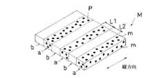
以下に本発明を、図面を参照しながら説明する。図1は、本発明の高分子フィルム(M)の概念図であり、ポリマーマトリクス(P)中に金属微粒子(m)が分散している。また本発明の高分子フィルム(M)は金属微粒子(m)の分散部分(a)と非分散部分(b)を有する。分散部分(a)は同じ方向に繰り返し配列して、縞状構造を形成している。分散部分(a)の配列方向が縦方向である。 The present invention will be described below with reference to the drawings. FIG. 1 is a conceptual diagram of the polymer film (M) of the present invention, in which metal fine particles (m) are dispersed in a polymer matrix (P). The polymer film (M) of the present invention has a dispersed part (a) and a non-dispersed part (b) of the metal fine particles (m). The dispersed portions (a) are repeatedly arranged in the same direction to form a striped structure. The arrangement direction of the dispersed portions (a) is the vertical direction.
前記分散部分(a)における金属微粒子(m)の分布は特に制限はなく、ランダムであってもよいし、一定距離間隔に金属微粒子(m)が配置する規則的な分布であってもよい。さらに金属微粒子(m)の粒子同士が付着して数珠状になる部分があってもよい。数珠状部分は粒子間の距離が一方向において限りなく短くなることにより吸収異方性が大きくなる点で好ましいが、必ずしも必要ではない。 The distribution of the metal fine particles (m) in the dispersed portion (a) is not particularly limited, and may be random or may be a regular distribution in which the metal fine particles (m) are arranged at a constant distance. Further, there may be a beaded portion where the metal fine particles (m) are adhered to each other. The bead-shaped part is preferable in that the absorption anisotropy is increased by shortening the distance between the particles as much as possible in one direction, but it is not always necessary.
さらに、縞状構造はフィルム厚み方向において内部に連続的に形成されている。各分散部分(a)における金属微粒子(m)の粒径、分布頻度はそれぞれ同じであってもよいし異なっていてもよい。また、フィルム厚み方向においても金属微粒子(m)の粒径、分布頻度はそれぞれ同じであってもよいし異なっていてもよい。 Furthermore, the striped structure is continuously formed inside in the film thickness direction. The particle diameter and distribution frequency of the metal fine particles (m) in each dispersed portion (a) may be the same or different. In the film thickness direction, the particle size and distribution frequency of the metal fine particles (m) may be the same or different.
前記分散部分(a)の幅(L1)は、延伸後に可視光域での吸光度を高めるために5〜1万nm程度、さらには10〜3000nmであるのが好ましい。非分散部分(b)の幅(L2)は同様に5〜1万nm程度、さらには10〜3000nmであるのが好ましい。 The width (L1) of the dispersed portion (a) is preferably about 5 to 10,000 nm, more preferably 10 to 3000 nm in order to increase the absorbance in the visible light region after stretching. Similarly, the width (L2) of the non-dispersed portion (b) is preferably about 5 to 10,000 nm, more preferably 10 to 3000 nm.
図2は、ポリマーマトリクス(P)中に金属イオン(i)が溶解、分散している高分子フィルム(I)に、二光束干渉光を照射することにより、金属イオン(i)から金属微粒子(m)を生成し、金属微粒子(m)の分散部分(a)と、非分散部分(b)によって、マトリクス(P)中に縞状構造を形成した高分子フィルム(M)を製造する概念図である。 FIG. 2 shows a case where a polymer film (I) in which metal ions (i) are dissolved and dispersed in a polymer matrix (P) is irradiated with two-beam interference light to form metal fine particles (i) from metal ions (i). Conceptual diagram for producing a polymer film (M) in which a striped structure is formed in the matrix (P) by forming a m) and forming a dispersed portion (a) of the metal fine particles (m) and a non-dispersed portion (b) It is.
なお、図1、2では、非分散部分(b)には金属微粒子(m)が示されていないが、非分散部分(b)には分散部分(a)と縞状構造を形成できる程度に金属微粒子(m)を含んでいてもよい。また、分散部分(a)に金属イオン(i)を有することを排除するものでもない。 In FIGS. 1 and 2, the metal fine particles (m) are not shown in the non-dispersed portion (b), but the non-dispersed portion (b) can form a striped structure with the dispersed portion (a). Metal fine particles (m) may be included. Moreover, it does not exclude having the metal ion (i) in the dispersed portion (a).
本発明の高分子フィルム(M)において、マトリクスを形成するポリマーとしては、各種のものを特に制限なく使用できる。マトリクスを形成するポリマーは、通常、1種にて形成するが、2種以上により形成することもできる。たとえば、ポリビニルアルコールまたはその誘導体があげられる。ポリビニルアルコールの誘導体としては、ポリビニルホルマール、ポリビニルアセタール等があげられる他、エチレン、プロピレン等のオレフィン、アクリル酸、メタクリル酸、クロトン酸等の不飽和カルボン酸そのアルキルエステル、アクリルアミド等で変性したものがあげられる。ポリビニルアルコールの重合度は、1000〜10000程度、ケン化度は80〜100モル%程度のものが一般に用いられる。 In the polymer film (M) of the present invention, various polymers can be used without particular limitation as the polymer forming the matrix. The polymer for forming the matrix is usually formed of one type, but can be formed of two or more types. For example, polyvinyl alcohol or its derivative is mentioned. Derivatives of polyvinyl alcohol include polyvinyl formal, polyvinyl acetal and the like, olefins such as ethylene and propylene, unsaturated carboxylic acids such as acrylic acid, methacrylic acid and crotonic acid, alkyl esters thereof, acrylamide and the like. can give. Polyvinyl alcohol having a polymerization degree of about 1000 to 10000 and a saponification degree of about 80 to 100 mol% is generally used.
なお、前記ポリビニルアルコール系フィルム中には可塑剤等の添加剤を含有することもできる。可塑剤としては、ポリオールおよびその縮合物等があげられ、たとえばグリセリン、ジグリセリン、トリグリセリン、エチレングリコール、プロピレングリコール、ポリエチレングリコール等があげられる。可塑剤の使用量は、特に制限されないがポリビニルアルコール系フィルム中20重量%以下とするのが好適である。 In addition, additives, such as a plasticizer, can also be contained in the said polyvinyl alcohol-type film. Examples of the plasticizer include polyols and condensates thereof, and examples thereof include glycerin, diglycerin, triglycerin, ethylene glycol, propylene glycol, and polyethylene glycol. The amount of the plasticizer used is not particularly limited, but is preferably 20% by weight or less in the polyvinyl alcohol film.
また前記ポリマーとしては、例えばポリエチレンテレフタレートやポリエチレンナフタレート等のポリエステル系樹脂;ポリスチレンやアクリロニトリル・スチレン共重合体(AS樹脂)等のスチレン系樹脂;ポリエチレン、ポリプロピレン、シクロ系ないしはノルボルネン構造を有するポリオレフィン、エチレン・プロピレン共重合体等のオレフィン系樹脂等があげられる。さらには、塩化ビニル系樹脂、セルロース系樹脂、アクリル系樹脂、アミド系樹脂、イミド系樹脂、スルホン系ポリマー、ポリエーテルスルホン系樹脂、ポリエーテルエーテルケトン系樹脂ポリマー、ポリフェニレンスルフィド系樹脂、塩化ビニリデン系樹脂、ビニルブチラール系樹脂、アリレート系樹脂、ポリオキシメチレン系樹脂、シリコーン系樹脂、ウレタン系樹脂等があげられる。これらは1種または2種以上を組み合わせることができる。また、フェノール系、メラミン系、アクリル系、ウレタン系、アクリルウレタン系、エポキシ系、シリコーン系等の熱硬化型または紫外線硬化型の樹脂の硬化物を用いることもできる。 Examples of the polymer include polyester resins such as polyethylene terephthalate and polyethylene naphthalate; styrene resins such as polystyrene and acrylonitrile / styrene copolymer (AS resin); polyolefins having polyethylene, polypropylene, cyclo or norbornene structures, Examples thereof include olefin resins such as ethylene / propylene copolymers. Furthermore, vinyl chloride resin, cellulose resin, acrylic resin, amide resin, imide resin, sulfone polymer, polyether sulfone resin, polyether ether ketone resin polymer, polyphenylene sulfide resin, vinylidene chloride Examples thereof include resins, vinyl butyral resins, arylate resins, polyoxymethylene resins, silicone resins, urethane resins and the like. These can be used alone or in combination of two or more. In addition, a cured product of a thermosetting or ultraviolet curable resin such as phenol, melamine, acrylic, urethane, acrylurethane, epoxy, or silicone can also be used.
前記ポリマーにより形成されるフィルムは、延伸処理により複屈折が付与される。したがって、前記ポリマーは、複屈折を生じやすい異方性を有するものが好ましく、ポリビニルアルコール、ポリカーボネート、スルホン系ポリマー等が好適である。 A film formed of the polymer is given birefringence by a stretching process. Therefore, the polymer preferably has anisotropy that easily causes birefringence, and polyvinyl alcohol, polycarbonate, sulfone polymer and the like are preferable.
前記ポリマーマトリクス中に分散されている金属微粒子は、可視光域に吸収を持つものであれば特に制限されない。金属としては、たとえば銀、銅、金、白金、アルミニウム、パラジウム、鉄、クロム、ニッケル、マンガン、スズ、コバルト、チタン、マグネシウム、リチウム等を例示できる。 The metal fine particles dispersed in the polymer matrix are not particularly limited as long as they have absorption in the visible light region. Examples of the metal include silver, copper, gold, platinum, aluminum, palladium, iron, chromium, nickel, manganese, tin, cobalt, titanium, magnesium, and lithium.
本発明の高分子フィルム(M)の製造方法は特に制限されないが、たとえば、ポリマーマトリクス中に金属イオンが分散している高分子フィルム(I)に、二光束干渉光を照射することにより得られる。 Although the manufacturing method in particular of the polymer film (M) of this invention is not restrict | limited, For example, it obtains by irradiating the polymer film (I) in which the metal ion is disperse | distributing in a polymer matrix with two-beam interference light. .
高分子フィルム(I)は、前記ポリマーを含有する溶液に、金属イオンを分散含有させた混合溶液を調製し、その混合溶液を製膜することにより得られる。 The polymer film (I) is obtained by preparing a mixed solution in which metal ions are dispersed and contained in a solution containing the polymer, and forming the mixed solution into a film.
ポリマー溶液に用いる溶媒としては、ポリマーが溶解するものであれば特に制限はない。たとえば、水;メタノール、エタノール、n−プロピルアルコール、iso−プロピルアルコール、n−ブチルアルコール、iso−ブチルアルコール、tert−ブチルアルコール等のアルコール類;トルエン等の芳香族類;アセトン、メチルエチルケトン、シクロヘキサノン、シクロペンタノン、シクロヘプタノン、2−ヘプタノン、メチルイソブチルケトン、ブチルラクトン等のケトン類;酢酸メチル、酢酸エチル、酢酸プロピル、プロピオン酸メチル、プロピオン酸エチル等のエステル類等があげられる。なお、ポリマーとして、ポリビニルアルコール等の水溶性のものを用いる場合には、溶媒としては水が好適に用いられる。ポリマー溶液の濃度は、通常、0.05〜30重量%程度に調整するのが好ましい。 The solvent used in the polymer solution is not particularly limited as long as the polymer dissolves. For example, water; alcohol such as methanol, ethanol, n-propyl alcohol, iso-propyl alcohol, n-butyl alcohol, iso-butyl alcohol, tert-butyl alcohol; aromatics such as toluene; acetone, methyl ethyl ketone, cyclohexanone, Examples thereof include ketones such as cyclopentanone, cycloheptanone, 2-heptanone, methyl isobutyl ketone, and butyl lactone; esters such as methyl acetate, ethyl acetate, propyl acetate, methyl propionate, and ethyl propionate. In addition, when water-soluble things, such as polyvinyl alcohol, are used as a polymer, water is used suitably as a solvent. The concentration of the polymer solution is usually preferably adjusted to about 0.05 to 30% by weight.
金属イオンの分散含有は、金属イオンになりうる金属化合物を配合することにより行なう。金属化合物は、還元・析出等により金属微粒子を形成することができるものを用いることができる。金属化合物としては、無機金属化合物、有機金属化合物、無機金属化合物と有機金属化合物の錯体、有機金属化合物と有機金属化合物の錯体があげられる。金属化合物としては、金属のハロゲン化物、金属の硝酸化合物、金属の酢酸化合物、金属のトリフルオロ酢酸化合物、金属のアセチルアセトン化合物、金属のトリフルオロアセチルアセトン化合物、金属のへキサフルオロアセチルアセトン化合物等があげられる。また、以上の化合物とアセチルアセトン、1,1,1−トリフルオロアセチルアセトン、1,1,1,5,5,5−へキサフルオロアセチルアセトンを混合することによって得られた錯体なども使用可能である。金属化合物は1種を用いてもよいし、二種以上を組み合わせて用いてもよい。 The metal ions are dispersed and contained by blending a metal compound that can be converted into metal ions. As the metal compound, those capable of forming metal fine particles by reduction / precipitation or the like can be used. Examples of the metal compound include an inorganic metal compound, an organometallic compound, a complex of an inorganic metal compound and an organometallic compound, and a complex of an organometallic compound and an organometallic compound. Examples of the metal compound include a metal halide, a metal nitric acid compound, a metal acetic acid compound, a metal trifluoroacetic acid compound, a metal acetylacetone compound, a metal trifluoroacetylacetone compound, and a metal hexafluoroacetylacetone compound. . In addition, a complex obtained by mixing the above compound with acetylacetone, 1,1,1-trifluoroacetylacetone, 1,1,1,5,5,5-hexafluoroacetylacetone, and the like can also be used. 1 type may be used for a metal compound and it may use it in combination of 2 or more type.
金属化合物の含有量は、マトリクス形成ポリマー100g(固形分)に対して1ミリモル以上であるのが好ましい。前記金属化合物の割合は、ポリマー100g(固形分)に対して5ミリモル以上、さらには7.5ミリモル以上、さらに10ミリモル以上であるのが好ましい。金属化合物の割合が1ミリモル未満では、二光束干渉光の照射により、金属イオンから還元、生成される金属微粒子が少なくなる。その結果、金属微粒子間の相互作用の効果を奏し難く、広い波長帯域で吸光特性を有する高分子フィルムが得られない。 The content of the metal compound is preferably 1 mmol or more with respect to 100 g (solid content) of the matrix-forming polymer. The ratio of the metal compound is preferably 5 mmol or more, more preferably 7.5 mmol or more, and more preferably 10 mmol or more with respect to 100 g (solid content) of the polymer. When the ratio of the metal compound is less than 1 millimolar, metal fine particles reduced and generated from metal ions are reduced by irradiation with two-beam interference light. As a result, it is difficult to obtain an effect of interaction between the metal fine particles, and a polymer film having light absorption characteristics in a wide wavelength band cannot be obtained.
一方、金属化合物の割合が高くなると、還元、生成される金属性粒子の凝集が起こり、当該金属微粒子の分布異方性制御が難しくなる。これらから、金属化合物の割合は、ポリマー100g(固形分)に対して1000ミリモル以下、さらには500ミリモル以下であるのが好ましい。 On the other hand, when the ratio of the metal compound is increased, reduction and aggregation of the generated metallic particles occur, making it difficult to control the distribution anisotropy of the metal fine particles. From these, the ratio of the metal compound is preferably 1000 mmol or less, more preferably 500 mmol or less, with respect to 100 g (solid content) of the polymer.
一方、金属イオンは、通常、分散溶液として前記ポリマー溶液に混合される。金属イオンの分散溶液の濃度は、通常、0.01〜25重量%程度に調整するのが好ましい。 On the other hand, metal ions are usually mixed in the polymer solution as a dispersion solution. In general, the concentration of the metal ion dispersion is preferably adjusted to about 0.01 to 25% by weight.
ポリマー溶液と、金属イオンを分散させた溶液(金属化合物を含有する溶液)の混合割合は、得られる混合溶液中におけるポリマーと金属化合物との割合が前記範囲となるように適宜に調整される。 The mixing ratio of the polymer solution and a solution in which metal ions are dispersed (a solution containing a metal compound) is appropriately adjusted so that the ratio of the polymer and the metal compound in the obtained mixed solution is within the above range.
前記金属イオンは、ポリマー中において外部エネルギーに対して不安定であり、露光光に対する反応性は、マトリクス材料、金属化合物種、露光光光源、使用環境等により異なる。これらに対する反応挙動を制御するため、ポリマーマトリクス中に金属イオンが分散している高分子フィルム(I)中には、イオン安定化剤、界面活性剤、pH調整剤、分光増感剤などの添加物を添加することができる。かかる添加剤は、前記高分子フィルムの製膜に用いる混合溶液中に含有させることができる。その他、前記溶液中には、分散剤、色相調整剤、紫外線吸収剤、難燃剤、酸化防止剤、増粘剤・可塑剤等の各種の添加剤を含有させることができる。 The metal ions are unstable with respect to external energy in the polymer, and the reactivity to exposure light varies depending on the matrix material, the metal compound type, the exposure light source, the use environment, and the like. In order to control the reaction behavior to these, the addition of ion stabilizers, surfactants, pH adjusters, spectral sensitizers, etc. in the polymer film (I) in which metal ions are dispersed in the polymer matrix Can be added. Such an additive can be contained in a mixed solution used for forming the polymer film. In addition, the solution may contain various additives such as a dispersant, a hue adjuster, an ultraviolet absorber, a flame retardant, an antioxidant, a thickener and a plasticizer.
イオン安定化剤は、金属イオンおよび還元処理後の金属微粒子をポリマーマトリクス中に安定に存在させる。ポリマー中の金属イオンは不安定な状態であり、特に銀イオンは不安定で酸化しやすい。また、均一な粒度分布をもつ構造を得るためには、フィルム製膜時に金属イオンの酸化・還元を防止し、ポリマー中に安定的にイオンを閉じ込め、露光時の反応のみにより金属微粒子を析出させることが重要である。イオン安定化剤としては、金属イオンと錯体を形成する錯形成剤が好ましい。例えば、塩素イオン、臭素イオン、ヨウ素イオン、チオ硫酸イオン、アンモニア、シアナイドイオン、チオシアネートイオン、亜硫酸イオン、チオ尿素、脂肪族1級アミン(直鎖又は分岐したドデシルアミン、ヘキシルアミン、ノニルアミン、ペンタデシルアミンなど)、環状アミン(ピリジン、イミダゾール、2−メチルイミダゾール、トリアゾール、チアジアゾール、ピコリン、ピぺラジン、ピロール、ピベリジン、ピラジン、ピリミジン、ピリダジン、イソチアゾール、キノリン、インキノリンなど)、アルカノールアミン(ジエタノールアミン、モノエタノールアミン、インプロパノールアミン、トリ−イソプロパノールアミンなど)、ポリアミン(トリエチレンテトラミン、ペンタエチレンヘキサミン、ジエチレントリアミン、エチレンジアミンなど)、アミノ酸(アラニン、アルギニン、ヒスチジン、システイン、メチオニン、グルタミンなど)、チオール(チオグリコールなど)、チオセミカルバジド、チオウラシルが挙げられる。より具体的には、塩化ナトリウム、2−メチルイミダゾール、2−メチルイミダゾール−4−ジチオカルボン酸、チオ硫酸ナトリウム、チオシアン酸ナトリウム、チオ硫酸ナトリウム、イミダゾール等があげられる。 The ion stabilizer stably causes metal ions and metal fine particles after the reduction treatment to be present in the polymer matrix. Metal ions in the polymer are unstable, and silver ions are particularly unstable and easily oxidize. In addition, in order to obtain a structure with a uniform particle size distribution, oxidation / reduction of metal ions is prevented during film formation, ions are stably trapped in the polymer, and metal fine particles are deposited only by reaction during exposure. This is very important. As the ion stabilizer, a complexing agent that forms a complex with a metal ion is preferable. For example, chlorine ion, bromine ion, iodine ion, thiosulfate ion, ammonia, cyanide ion, thiocyanate ion, sulfite ion, thiourea, aliphatic primary amine (linear or branched dodecylamine, hexylamine, nonylamine, penta Decylamine, etc.), cyclic amines (pyridine, imidazole, 2-methylimidazole, triazole, thiadiazole, picoline, piperazine, pyrrole, piperidine, pyrazine, pyrimidine, pyridazine, isothiazole, quinoline, innoline, etc.), alkanolamine ( Diethanolamine, monoethanolamine, inpropanolamine, tri-isopropanolamine, etc.), polyamines (triethylenetetramine, pentaethylenehexamine, diethylenetriamine, Etc. diamine), amino acids (alanine, arginine, histidine, cysteine, methionine, glutamine, etc.), and thiol (thioglycolic), thiosemicarbazide, and thiouracil is. More specifically, sodium chloride, 2-methylimidazole, 2-methylimidazole-4-dithiocarboxylic acid, sodium thiosulfate, sodium thiocyanate, sodium thiosulfate, imidazole and the like can be mentioned.
界面活性剤は、金属イオンの安定化、さらに析出した金属微粒子のパターン(縞状構造)の精度向上、パターンの安定化のために添加することができる。界面活性剤の種類としては、アニオン系界面活性剤、ノニオン系界面活性剤、両面活性剤のいずれでもよく、市販品として使用されているものを使用することが可能である。例えば、アルキル硫酸エステル塩,ポリオキシエチレンアルキルエーテル硫酸エステル塩、アルキルベンゼンスルフォン酸塩、アルキルナフタレンスルフォン酸塩、アルキルスルホコハク酸塩、ポリオキシエチレン、ポリオキシアルキレン、ポリオキシエチレン誘導体、ソルビタン脂肪酸エステル、ソルビトール脂肪酸エステル、グリセリン脂肪酸エステル、ポリオキシエチレン脂肪酸エステル、硬化ひまし油、ポリオキシエチレン、アルキルアミン、アルキルアルカノールアミドなどがあげられる。 The surfactant can be added to stabilize the metal ions, further improve the accuracy of the deposited metal fine particle pattern (striped structure), and stabilize the pattern. As the type of the surfactant, any of an anionic surfactant, a nonionic surfactant, and a double-sided surfactant may be used, and commercially available products can be used. For example, alkyl sulfate ester salt, polyoxyethylene alkyl ether sulfate ester, alkylbenzene sulfonate, alkyl naphthalene sulfonate, alkyl sulfosuccinate, polyoxyethylene, polyoxyalkylene, polyoxyethylene derivatives, sorbitan fatty acid ester, sorbitol Examples include fatty acid esters, glycerin fatty acid esters, polyoxyethylene fatty acid esters, hydrogenated castor oil, polyoxyethylene, alkylamines, and alkylalkanolamides.
pH調整剤は、前記混合溶液中の金属イオンの平衡状態を制御し、薄膜形成時のイオン安定性、干渉光露光時の金属微粒子の生成を安定化するために用いる。混合溶液は、pH6〜pH8程度が好ましく、さらに好ましくは6.5〜7.5である。pHを上記値内に調整するため、一般的に知られるpH調整剤を添加することができる。 The pH adjuster is used to control the equilibrium state of the metal ions in the mixed solution, and to stabilize the ion stability during the formation of the thin film and the generation of metal fine particles during the interference light exposure. The mixed solution preferably has a pH of about 6 to 8, more preferably 6.5 to 7.5. In order to adjust the pH within the above value, a generally known pH adjusting agent can be added.
分光増感剤は、干渉光に対する金属化合物の感光性を高めるために分光増感剤を添加することができる。一般的に知られている分光増感剤の例としては、ベンゾトリアゾール系、シアノアクリレート系、ベンゾフェノン系吸収剤等があげられる。これらの分光増感剤を金属化合物(金属イオン)の種類により適宜選択することにより、照射レーザの波長域における感光性を高めることが可能である。例えば、銀イオンの紫外域における吸収感度を高めるためには、ベンゾフェノン系吸収剤が有効である。 A spectral sensitizer can be added to increase the photosensitivity of the metal compound to interference light. Examples of generally known spectral sensitizers include benzotriazole, cyanoacrylate, and benzophenone absorbers. By appropriately selecting these spectral sensitizers depending on the type of metal compound (metal ion), it is possible to increase the photosensitivity in the wavelength range of the irradiation laser. For example, in order to increase the absorption sensitivity of silver ions in the ultraviolet region, a benzophenone-based absorbent is effective.
前記ポリマー溶液に、金属イオンを分散含有させた混合溶液は、製膜して高分子フィルム(I)を得る。フィルムの形成方法としては、キャスティング法、押し出し溶融法、ラミネート成形法、射出成形法、スピンコート法、ロール成形法、流延成形法などの各種の方法を採用できる。フィルム成形にあったっては、溶液の粘度、乾燥速度を調整して行なう。フィルム厚みは特に制限されないが、通常、5〜80μm程度である。 A mixed solution in which metal ions are dispersed and contained in the polymer solution is formed into a polymer film (I). As a film forming method, various methods such as a casting method, an extrusion melting method, a laminate molding method, an injection molding method, a spin coating method, a roll molding method, and a casting method can be employed. In film formation, the viscosity of the solution and the drying speed are adjusted. The film thickness is not particularly limited, but is usually about 5 to 80 μm.
本発明の高分子フィルム(M)は、上記製膜したフィルム(I)に、二光束干渉光を照射することにより得られる。上記フィルム(I)は、ポリマーマトリクス中に金属イオンを含み、これに二光束干渉光を照射することにより、選択的に金属イオンから金属微粒子から生成する。これにより縞状構造を形成している本発明の高分子フィルム(M)を作製する。 The polymer film (M) of the present invention can be obtained by irradiating the film (I) thus formed with two-beam interference light. The film (I) contains metal ions in a polymer matrix, and is selectively formed from metal ions from metal ions by irradiating the light beam with two-beam interference light. Thereby, the polymer film (M) of the present invention having a striped structure is produced.
二光束干渉光の光源としては、位相の揃ったレーザ光源が好ましく、ヘリウムネオンレーザー、アルゴンレーザー、Nd:YAGレーザ、THG:YAGレーザなどの各種レーザがあげられる。干渉縞の間隔は、二光束光線の上記高分子フィルム(I)への入射角度および光路長により決定される。高分子フィルム(M)に形成されている縞状構造内部の金属微粒子の分布(縞状構造の間隔)は、金属微粒子の濃度、照射光の強度、照射時間などから任意に設計することができる。照射光の強度は50mW〜500mW程度、さらには、100mW〜300mW、照射時間は1秒間〜30分間程度、さらには5秒間〜10分間であるのが好ましい。 As the light source of the two-beam interference light, a laser light source having a uniform phase is preferable, and various lasers such as a helium neon laser, an argon laser, an Nd: YAG laser, and a THG: YAG laser can be used. The interval between the interference fringes is determined by the incident angle and optical path length of the two-beam light beam on the polymer film (I). The distribution (interval of the stripe structure) of the metal fine particles inside the stripe structure formed in the polymer film (M) can be arbitrarily designed from the concentration of the metal fine particles, the intensity of irradiation light, the irradiation time, and the like. . The intensity of irradiation light is preferably about 50 mW to 500 mW, more preferably 100 mW to 300 mW, and the irradiation time is preferably about 1 second to 30 minutes, and further preferably 5 seconds to 10 minutes.
次いで、前記高分子フィルム(M)を延伸処理する。延伸方向は、少なくとも高分子フィルム(M)の縞状構造の縦方向と平行な方向を含む。延伸は一軸延伸により、ポリマーマトリクスを形成するポリマーに一軸性の複屈折を付与し、偏光子を得る。延伸により等方的に分散されていた粒子が、異方性の分布もしくは一方向への配列状態を持つようになり、吸収の異方性が発現する。 Next, the polymer film (M) is stretched. The stretching direction includes at least a direction parallel to the longitudinal direction of the striped structure of the polymer film (M). Stretching is uniaxial stretching that imparts uniaxial birefringence to the polymer forming the polymer matrix to obtain a polarizer. The particles that are isotropically dispersed by stretching come to have an anisotropic distribution or an aligned state in one direction, and anisotropy of absorption is manifested.
延伸方法は空気中での延伸、金属ロールへの接触等による乾式延伸でもよいし、ポリマーがポリビニルアルコールのような水溶性の場合には、水中での湿式延伸でもよい。なお、延伸手段はポリマーの種類に応じて、そのガラス転移温度の付近において伸長が可能である温度にて行なう。延伸倍率は特に制限されないが、通常、1.1〜10倍程度、さらには、2〜10倍とするのが好ましい。 The stretching method may be stretching in air, dry stretching by contact with a metal roll, or the like, or may be wet stretching in water when the polymer is water-soluble such as polyvinyl alcohol. The stretching means is performed at a temperature at which stretching is possible in the vicinity of the glass transition temperature depending on the type of polymer. The draw ratio is not particularly limited, but is usually about 1.1 to 10 times, more preferably 2 to 10 times.
偏光子の厚さは、特に制限されないが、通常、5〜80μm程度である。得られた偏光子は、常法に従って、その少なくとも片面に透明保護層を設けた偏光板とすることができる。透明保護層はポリマーによる塗布層として、またはフィルムのラミネート層等として設けることができる。透明保護層を形成する、透明ポリマーまたはフィルム材料としては、適宜な透明材料を用いうるが、透明性や機械的強度、熱安定性や水分遮断性などに優れるものが好ましく用いられる。前記透明保護層を形成する材料としては、例えばポリエチレンテレフタレートやポリエチレンナフタレート等のポリエステル系ポリマー、二酢酸セルロースや三酢酸セルロース等のセルロース系ポリマー、ポリメチルメタクリレート等のアクリル系ポリマー、ポリスチレンやアクリロニトリル・スチレン共重合体(AS樹脂)等のスチレン系ポリマー、ポリカーボネート系ポリマーなどがあげられる。また、ポリエチレン、ポリプロピレン、シクロ系ないしはノルボルネン構造を有するポリオレフィン、エチレン・プロピレン共重合体の如きポリオレフィン系ポリマー、塩化ビニル系ポリマー、ナイロンや芳香族ポリアミド等のアミド系ポリマー、イミド系ポリマー、スルホン系ポリマー、ポリエーテルスルホン系ポリマー、ポリエーテルエーテルケトン系ポリマー、ポリフェニレンスルフィド系ポリマー、ビニルアルコール系ポリマー、塩化ビニリデン系ポリマー、ビニルブチラール系ポリマー、アリレート系ポリマー、ポリオキシメチレン系ポリマー、エポキシ系ポリマー、あるいは前記ポリマーのブレンド物なども前記透明保護層を形成するポリマーの例としてあげられる。 The thickness of the polarizer is not particularly limited, but is usually about 5 to 80 μm. The obtained polarizer can be made into a polarizing plate provided with a transparent protective layer on at least one surface thereof according to a conventional method. The transparent protective layer can be provided as a polymer-coated layer or a film laminate layer. As the transparent polymer or film material for forming the transparent protective layer, an appropriate transparent material can be used, but a material excellent in transparency, mechanical strength, thermal stability, moisture barrier property and the like is preferably used. Examples of the material for forming the transparent protective layer include polyester polymers such as polyethylene terephthalate and polyethylene naphthalate, cellulose polymers such as cellulose diacetate and cellulose triacetate, acrylic polymers such as polymethyl methacrylate, polystyrene, acrylonitrile, Examples thereof include styrene polymers such as styrene copolymers (AS resins), polycarbonate polymers, and the like. In addition, polyethylene, polypropylene, polyolefins having a cyclo or norbornene structure, polyolefin polymers such as ethylene / propylene copolymers, vinyl chloride polymers, amide polymers such as nylon and aromatic polyamide, imide polymers, sulfone polymers , Polyether sulfone polymer, polyether ether ketone polymer, polyphenylene sulfide polymer, vinyl alcohol polymer, vinylidene chloride polymer, vinyl butyral polymer, arylate polymer, polyoxymethylene polymer, epoxy polymer, or the above Polymer blends and the like are also examples of the polymer that forms the transparent protective layer.
また、特開2001−343529号公報(WO01/37007)に記載のポリマーフィルム、たとえば、(A)側鎖に置換および/または非置換イミド基を有する熱可塑性樹脂と、(B)側鎖に置換および/非置換フェニルならびにニトリル基を有する熱可塑性樹脂を含有する樹脂組成物があげられる。具体例としてはイソブチレンとN−メチルマレイミドからなる交互共重合体とアクリロニトリル・スチレン共重合体とを含有する樹脂組成物のフィルムがあげられる。フィルムは樹脂組成物の混合押出品などからなるフィルムを用いることができる。 Moreover, the polymer film described in JP-A-2001-343529 (WO01 / 37007), for example, (A) a thermoplastic resin having a substituted and / or unsubstituted imide group in the side chain, and (B) a substitution in the side chain And / or a resin composition containing an unsubstituted phenyl and a thermoplastic resin having a nitrile group. A specific example is a film of a resin composition containing an alternating copolymer composed of isobutylene and N-methylmaleimide and an acrylonitrile / styrene copolymer. As the film, a film made of a mixed extruded product of the resin composition or the like can be used.
偏光特性や耐久性などの点より、特に好ましく用いることができる透明保護層は、表面をアルカリなどでケン化処理したトリアセチルセルロースフィルムである。透明保護層の厚さは、任意であるが一般には偏光板の薄型化などを目的に500μm以下、さらには1〜300μm、特に5〜300μmが好ましい。なお、偏光子の両側に透明保護層を設ける場合は、その表裏で異なるポリマー等からなる透明保護フィルムを用いるができる。 The transparent protective layer that can be particularly preferably used in terms of polarization characteristics and durability is a triacetyl cellulose film whose surface is saponified with alkali or the like. The thickness of the transparent protective layer is arbitrary, but is generally 500 μm or less, more preferably 1 to 300 μm, and particularly preferably 5 to 300 μm for the purpose of reducing the thickness of the polarizing plate. In addition, when providing a transparent protective layer on both sides of a polarizer, the transparent protective film which consists of a polymer etc. which is different in the front and back can be used.
また、透明保護フィルムは、できるだけ色付きがないことが好ましい。したがって、Rth=[(nx+ny)/2−nz]・d(ただし、nx、nyはフィルム平面内の主屈折率、nzはフィルム厚方向の屈折率、dはフィルム厚みである)で表されるフィルム厚み方向の位相差値が−90nm〜+75nmである保護フィルムが好ましく用いられる。かかる厚み方向の位相差値(Rth)が−90nm〜+75nmのものを使用することにより、保護フィルムに起因する偏光板の着色(光学的な着色)をほぼ解消することができる。厚み方向位相差値(Rth)は、さらに好ましくは−80nm〜+60nm、特に−70nm〜+45nmが好ましい。 Moreover, it is preferable that a transparent protective film has as little color as possible. Therefore, Rth = [(nx + ny) / 2−nz] · d (where nx and ny are the main refractive index in the plane of the film, nz is the refractive index in the film thickness direction, and d is the film thickness). A protective film having a retardation value in the film thickness direction of −90 nm to +75 nm is preferably used. By using a film having a thickness direction retardation value (Rth) of −90 nm to +75 nm, the coloring (optical coloring) of the polarizing plate caused by the protective film can be almost eliminated. The thickness direction retardation value (Rth) is more preferably −80 nm to +60 nm, and particularly preferably −70 nm to +45 nm.
前記透明保護フィルムの偏光子を接着させない面には、ハードコート層や反射防止処理、スティッキング防止や、拡散ないしアンチグレアを目的とした処理を施したものであってもよい。 The surface of the transparent protective film to which the polarizer is not adhered may be subjected to a hard coat layer, an antireflection treatment, an antisticking treatment, or a treatment for diffusion or antiglare.
ハードコート処理は偏光板表面の傷付き防止などを目的に施されるものであり、例えばアクリル系、シリコーン系などの適宜な紫外線硬化型樹脂による硬度や滑り特性等に優れる硬化皮膜を透明保護フィルムの表面に付加する方式などにて形成することができる。反射防止処理は偏光板表面での外光の反射防止を目的に施されるものであり、従来に準じた反射防止膜などの形成により達成することができる。また、スティッキング防止処理は隣接層との密着防止を目的に施される。 The hard coat treatment is applied for the purpose of preventing scratches on the surface of the polarizing plate. For example, a transparent protective film with a cured film excellent in hardness, sliding properties, etc. by an appropriate ultraviolet curable resin such as acrylic or silicone is used. It can be formed by a method of adding to the surface of the film. The antireflection treatment is performed for the purpose of preventing reflection of external light on the surface of the polarizing plate, and can be achieved by forming an antireflection film or the like according to the conventional art. Further, the anti-sticking treatment is performed for the purpose of preventing adhesion with an adjacent layer.
またアンチグレア処理は偏光板の表面で外光が反射して偏光板透過光の視認を阻害することの防止等を目的に施されるものであり、例えばサンドブラスト方式やエンボス加工方式による粗面化方式や透明微粒子の配合方式などの適宜な方式にて透明保護フィルムの表面に微細凹凸構造を付与することにより形成することができる。前記表面微細凹凸構造の形成に含有させる微粒子としては、例えば平均粒径が0.5〜50μmのシリカ、アルミナ、チタニア、ジルコニア、酸化錫、酸化インジウム、酸化カドミウム、酸化アンチモン等からなる導電性のこともある無機系微粒子、架橋又は未架橋のポリマー等からなる有機系微粒子などの透明微粒子が用いられる。表面微細凹凸構造を形成する場合、微粒子の使用量は、表面微細凹凸構造を形成する透明樹脂100重量部に対して一般的に2〜50重量部程度であり、5〜25重量部が好ましい。アンチグレア層は、偏光板透過光を拡散して視角などを拡大するための拡散層(視角拡大機能など)を兼ねるものであってもよい。 The anti-glare treatment is applied for the purpose of preventing the outside light from being reflected on the surface of the polarizing plate and obstructing the visibility of the light transmitted through the polarizing plate. For example, the surface is roughened by a sandblasting method or an embossing method. It can be formed by imparting a fine concavo-convex structure to the surface of the transparent protective film by an appropriate method such as a blending method of transparent particles. The fine particles to be included in the formation of the surface fine concavo-convex structure are, for example, conductive materials made of silica, alumina, titania, zirconia, tin oxide, indium oxide, cadmium oxide, antimony oxide or the like having an average particle size of 0.5 to 50 μm. In some cases, transparent fine particles such as inorganic fine particles, organic fine particles composed of a crosslinked or uncrosslinked polymer, and the like are used. When forming a surface fine uneven structure, the amount of fine particles used is generally about 2 to 50 parts by weight, preferably 5 to 25 parts by weight, based on 100 parts by weight of the transparent resin forming the surface fine uneven structure. The antiglare layer may also serve as a diffusion layer (viewing angle expanding function or the like) for diffusing the light transmitted through the polarizing plate to expand the viewing angle.
なお、前記反射防止層、スティッキング防止層、拡散層やアンチグレア層等は、透明保護フィルムそのものに設けることができるほか、別途光学層として透明保護層とは別体のものとして設けることもできる。 The antireflection layer, antisticking layer, diffusing layer, antiglare layer and the like can be provided on the transparent protective film itself, or can be provided separately from the transparent protective layer as an optical layer.
前記偏光子と透明保護フィルムとの接着処理には、接着剤が用いられる。接着剤としては、イソシアネート系接着剤、ポリビニルアルコール系接着剤、ゼラチン系接着剤、ビニル系ラテックス系、水系ポリエステル等を例示できる。前記接着剤は、架橋剤、各種添加剤を含有することができる。前記接着剤は、通常、水溶液からなる接着剤として用いられ、通常、0.5〜60重量%の固形分を含有してなる。 An adhesive is used for the adhesion treatment between the polarizer and the transparent protective film. Examples of the adhesive include isocyanate adhesives, polyvinyl alcohol adhesives, gelatin adhesives, vinyl latexes, and water-based polyesters. The adhesive may contain a crosslinking agent and various additives. The said adhesive agent is normally used as an adhesive agent which consists of aqueous solution, and contains 0.5 to 60 weight% of solid content normally.
本発明の偏光板は、前記透明保護フィルムと偏光子を、前記接着剤を用いて貼り合わせることにより製造する。接着剤の塗布は、透明保護フィルム、偏光子のいずれに行ってもよく、両者に行ってもよい。貼り合わせ後には、乾燥工程を施し、塗布乾燥層からなる接着層を形成する。偏光子と透明保護フィルムの貼り合わせは、ロールラミネーター等により行なうことができる。接着層の厚さは、特に制限されないが、通常0.1〜5μm程度である。 The polarizing plate of the present invention is produced by bonding the transparent protective film and the polarizer using the adhesive. The adhesive may be applied to either the transparent protective film or the polarizer, or to both. After the bonding, a drying process is performed to form an adhesive layer composed of a coating dry layer. The polarizer and the transparent protective film can be bonded together using a roll laminator or the like. The thickness of the adhesive layer is not particularly limited, but is usually about 0.1 to 5 μm.
本発明の偏光板は、実用に際して他の光学層と積層した光学フィルムとして用いることができる。その光学層については特に限定はないが、例えば反射板や半透過板、位相差板(1/2や1/4等の波長板を含む)、視角補償フィルムなどの液晶表示装置等の形成に用いられることのある光学層を1層または2層以上用いることができる。特に、本発明の偏光板に更に反射板または半透過反射板が積層されてなる反射型偏光板または半透過型偏光板、偏光板に更に位相差板が積層されてなる楕円偏光板または円偏光板、偏光板に更に視角補償フィルムが積層されてなる広視野角偏光板、あるいは偏光板に更に輝度向上フィルムが積層されてなる偏光板が好ましい。 The polarizing plate of the present invention can be used as an optical film laminated with another optical layer in practical use. The optical layer is not particularly limited. For example, for forming a liquid crystal display device such as a reflection plate, a semi-transmission plate, a retardation plate (including wavelength plates such as 1/2 and 1/4), and a viewing angle compensation film. One or more optical layers that may be used can be used. In particular, a reflective polarizing plate or a semi-transmissive polarizing plate in which a polarizing plate or a semi-transmissive reflecting plate is further laminated on the polarizing plate of the present invention, an elliptical polarizing plate or a circularly polarizing plate in which a retardation plate is further laminated on the polarizing plate. A wide viewing angle polarizing plate obtained by further laminating a viewing angle compensation film on a plate or a polarizing plate, or a polarizing plate obtained by further laminating a brightness enhancement film on the polarizing plate is preferable.
反射型偏光板は、偏光板に反射層を設けたもので、視認側(表示側)からの入射光を反射させて表示するタイプの液晶表示装置などを形成するためのものであり、バックライト等の光源の内蔵を省略できて液晶表示装置の薄型化を図りやすいなどの利点を有する。反射型偏光板の形成は、必要に応じ透明保護層等を介して偏光板の片面に金属等からなる反射層を付設する方式などの適宜な方式にて行なうことができる。 A reflective polarizing plate is a polarizing plate provided with a reflective layer, and is used to form a liquid crystal display device or the like that reflects incident light from the viewing side (display side). Such a light source can be omitted, and the liquid crystal display device can be easily thinned. The reflective polarizing plate can be formed by an appropriate method such as a method in which a reflective layer made of metal or the like is attached to one surface of the polarizing plate via a transparent protective layer or the like as necessary.
反射型偏光板の具体例としては、必要に応じマット処理した透明保護フィルムの片面に、アルミニウム等の反射性金属からなる箔や蒸着膜を付設して反射層を形成したものなどがあげられる。また前記透明保護フィルムに微粒子を含有させて表面微細凹凸構造とし、その上に微細凹凸構造の反射層を有するものなどもあげられる。前記した微細凹凸構造の反射層は、入射光を乱反射により拡散させて指向性やギラギラした見栄えを防止し、明暗のムラを抑制しうる利点などを有する。また微粒子含有の透明保護フィルムは、入射光及びその反射光がそれを透過する際に拡散されて明暗ムラをより抑制しうる利点なども有している。透明保護フィルムの表面微細凹凸構造を反映させた微細凹凸構造の反射層の形成は、例えば真空蒸着方式、イオンプレーティング方式、スパッタリング方式等の蒸着方式やメッキ方式などの適宜な方式で金属を透明保護層の表面に直接付設する方法などにより行なうことができる。 Specific examples of the reflective polarizing plate include those in which a reflective layer is formed by attaching a foil or a vapor deposition film made of a reflective metal such as aluminum on one side of a transparent protective film matted as necessary. Moreover, the transparent protective film contains fine particles so as to have a surface fine concavo-convex structure and a reflective layer having a fine concavo-convex structure thereon. The reflective layer having the fine concavo-convex structure has an advantage that incident light is diffused by irregular reflection to prevent directivity and glaring appearance and to suppress unevenness in brightness and darkness. The transparent protective film containing fine particles also has an advantage that incident light and its reflected light are diffused when passing through it, and light and dark unevenness can be further suppressed. The reflective layer of the fine concavo-convex structure reflecting the surface fine concavo-convex structure of the transparent protective film is formed by transparent the metal by an appropriate method such as a vapor deposition method such as a vacuum vapor deposition method, an ion plating method, a sputtering method, or a plating method. It can be performed by a method of attaching directly to the surface of the protective layer.
反射板は前記の偏光板の透明保護フィルムに直接付与する方式に代えて、その透明フィルムに準じた適宜なフィルムに反射層を設けてなる反射シートなどとして用いることもできる。なお反射層は、通常、金属からなるので、その反射面が透明保護フィルムや偏光板等で被覆された状態の使用形態が、酸化による反射率の低下防止、ひいては初期反射率の長期持続の点や、保護層の別途付設の回避の点などより好ましい。 Instead of the method of directly applying the reflecting plate to the transparent protective film of the polarizing plate, the reflecting plate can be used as a reflecting sheet provided with a reflecting layer on an appropriate film according to the transparent film. Since the reflective layer is usually made of metal, the usage form in which the reflective surface is covered with a transparent protective film, a polarizing plate or the like is used to prevent the reflectance from being lowered due to oxidation, and thus to maintain the initial reflectance for a long time. In addition, it is more preferable to avoid a separate attachment of the protective layer.
なお、半透過型偏光板は、上記において反射層で光を反射し、かつ透過するハーフミラー等の半透過型の反射層とすることにより得ることができる。半透過型偏光板は、通常液晶セルの裏側に設けられ、液晶表示装置などを比較的明るい雰囲気で使用する場合には、視認側(表示側)からの入射光を反射させて画像を表示し、比較的暗い雰囲気においては、半透過型偏光板のバックサイドに内蔵されているバックライト等の内蔵光源を使用して画像を表示するタイプの液晶表示装置などを形成できる。すなわち、半透過型偏光板は、明るい雰囲気下では、バックライト等の光源使用のエネルギーを節約でき、比較的暗い雰囲気下においても内蔵光源を用いて使用できるタイプの液晶表示装置などの形成に有用である。 The semi-transmissive polarizing plate can be obtained by using a semi-transmissive reflective layer such as a half mirror that reflects and transmits light with the reflective layer. A transflective polarizing plate is usually provided on the back side of a liquid crystal cell, and displays an image by reflecting incident light from the viewing side (display side) when a liquid crystal display device is used in a relatively bright atmosphere. In a relatively dark atmosphere, a liquid crystal display device or the like that displays an image using a built-in light source such as a backlight built in the back side of the transflective polarizing plate can be formed. In other words, the transflective polarizing plate is useful for forming a liquid crystal display device of a type that can save energy of using a light source such as a backlight in a bright atmosphere and can be used with a built-in light source even in a relatively dark atmosphere. It is.
偏光板に更に位相差板が積層されてなる楕円偏光板または円偏光板について説明する。直線偏光を楕円偏光または円偏光に変えたり、楕円偏光または円偏光を直線偏光に変えたり、あるいは直線偏光の偏光方向を変える場合に、位相差板などが用いられる。特に、直線偏光を円偏光に変えたり、円偏光を直線偏光に変える位相差板としては、いわゆる1/4波長板(λ/4板とも言う)が用いられる。1/2波長板(λ/2板とも言う)は、通常、直線偏光の偏光方向を変える場合に用いられる。 An elliptically polarizing plate or a circularly polarizing plate in which a retardation plate is further laminated on a polarizing plate will be described. A phase difference plate or the like is used when changing linearly polarized light to elliptically polarized light or circularly polarized light, changing elliptically polarized light or circularly polarized light to linearly polarized light, or changing the polarization direction of linearly polarized light. In particular, a so-called quarter-wave plate (also referred to as a λ / 4 plate) is used as a retardation plate that changes linearly polarized light into circularly polarized light or changes circularly polarized light into linearly polarized light. A half-wave plate (also referred to as a λ / 2 plate) is usually used when changing the polarization direction of linearly polarized light.
楕円偏光板はスーパーツイストネマチック(STN)型液晶表示装置の液晶層の複屈折により生じた着色(青又は黄)を補償(防止)して、前記着色のない白黒表示する場合などに有効に用いられる。更に、三次元の屈折率を制御したものは、液晶表示装置の画面を斜め方向から見た際に生じる着色も補償(防止)することができて好ましい。円偏光板は、例えば画像がカラー表示になる反射型液晶表示装置の画像の色調を整える場合などに有効に用いられ、また、反射防止の機能も有する。 The elliptically polarizing plate is effectively used for black and white display without the above color by compensating (preventing) the coloration (blue or yellow) generated by the birefringence of the liquid crystal layer of the super twist nematic (STN) type liquid crystal display device. It is done. Further, the one in which the three-dimensional refractive index is controlled is preferable because it can compensate (prevent) coloring that occurs when the screen of the liquid crystal display device is viewed from an oblique direction. The circularly polarizing plate is effectively used, for example, when adjusting the color tone of an image of a reflective liquid crystal display device in which an image is displayed in color, and also has an antireflection function.
上記した位相差板の具体例としては、ポリカーボネート、ポリビニルアルコール、ポリスチレン、ポリメチルメタクリレート、ポリプロピレンやその他のポリオレフィン、ポリアリレート、ポリアミドの如き適宜なポリマーからなるフィルムを延伸処理してなる複屈折性フィルムや液晶ポリマーの配向フィルム、液晶ポリマーの配向層をフィルムにて支持したものなどがあげられる。位相差板は、例えば各種波長板や液晶層の複屈折による着色や視角等の補償を目的としたものなどの使用目的に応じた適宜な位相差を有するものであってよく、2種以上の位相差板を積層して位相差等の光学特性を制御したものなどであってもよい。 Specific examples of the retardation plate include a birefringent film obtained by stretching a film made of an appropriate polymer such as polycarbonate, polyvinyl alcohol, polystyrene, polymethyl methacrylate, polypropylene, other polyolefins, polyarylate, and polyamide. And an alignment film of a liquid crystal polymer, and a liquid crystal polymer alignment layer supported by a film. The retardation plate may have an appropriate retardation according to the purpose of use, such as those for the purpose of compensating for various wavelength plates or birefringence of the liquid crystal layer, viewing angle, and the like. What laminated | stacked the phase difference plate and controlled optical characteristics, such as phase difference, etc. may be used.
また上記の楕円偏光板や反射型楕円偏光板は、偏光板又は反射型偏光板と位相差板を適宜な組合せで積層したものである。かかる楕円偏光板等は、(反射型)偏光板と位相差板の組合せとなるようにそれらを液晶表示装置の製造過程で順次別個に積層することによっても形成しうるが、前記の如く予め楕円偏光板等の光学フィルムとしたものは、品質の安定性や積層作業性等に優れて液晶表示装置などの製造効率を向上させうる利点がある。 The elliptical polarizing plate and the reflective elliptical polarizing plate are obtained by laminating a polarizing plate or a reflective polarizing plate and a retardation plate in an appropriate combination. Such an elliptically polarizing plate or the like can also be formed by sequentially laminating them sequentially in the manufacturing process of the liquid crystal display device so as to be a combination of a (reflective) polarizing plate and a retardation plate. An optical film such as a polarizing plate has an advantage that it can improve the production efficiency of a liquid crystal display device and the like because of excellent quality stability and lamination workability.
視角補償フィルムは、液晶表示装置の画面を、画面に垂直でなくやや斜めの方向から見た場合でも、画像が比較的鮮明にみえるように視野角を広げるためのフィルムである。このような視角補償位相差板としては、例えば位相差フィルム、液晶ポリマー等の配向フィルムや透明基材上に液晶ポリマー等の配向層を支持したものなどからなる。通常の位相差板は、その面方向に一軸に延伸された複屈折を有するポリマーフィルムが用いられるのに対し、視角補償フィルムとして用いられる位相差板には、面方向に二軸に延伸された複屈折を有するポリマーフィルムとか、面方向に一軸に延伸され厚さ方向にも延伸された厚さ方向の屈折率を制御した複屈折を有するポリマーや傾斜配向フィルムのような二方向延伸フィルムなどが用いられる。傾斜配向フィルムとしては、例えばポリマーフィルムに熱収縮フィルムを接着して加熱によるその収縮力の作用下にポリマーフィルムを延伸処理又は/及び収縮処理したものや、液晶ポリマーを斜め配向させたものなどが挙げられる。位相差板の素材原料ポリマーは、先の位相差板で説明したポリマーと同様のものが用いられ、液晶セルによる位相差に基づく視認角の変化による着色等の防止や良視認の視野角の拡大などを目的とした適宜なものを用いうる。 The viewing angle compensation film is a film for widening the viewing angle so that an image can be seen relatively clearly even when the screen of the liquid crystal display device is viewed from a slightly oblique direction rather than perpendicular to the screen. As such a viewing angle compensation phase difference plate, for example, a retardation film, an alignment film such as a liquid crystal polymer, or an alignment layer such as a liquid crystal polymer supported on a transparent substrate is used. A normal retardation plate uses a birefringent polymer film uniaxially stretched in the plane direction, whereas a retardation plate used as a viewing angle compensation film stretches biaxially in the plane direction. Birefringent polymer film, biaxially stretched film such as polymer with birefringence with a controlled refractive index in the thickness direction that is uniaxially stretched in the plane direction and stretched in the thickness direction, etc. Used. Examples of the inclined alignment film include a film obtained by bonding a heat shrink film to a polymer film and stretching or / and shrinking the polymer film under the action of the contraction force by heating, and a film obtained by obliquely aligning a liquid crystal polymer. Can be mentioned. The raw material polymer for the phase difference plate is the same as the polymer described in the previous phase difference plate, preventing coloration due to a change in the viewing angle based on the phase difference by the liquid crystal cell and expanding the viewing angle for good visual recognition. An appropriate one for the purpose can be used.
また良視認の広い視野角を達成する点などより、液晶ポリマーの配向層、特にディスコティック液晶ポリマーの傾斜配向層からなる光学的異方性層をトリアセチルセルロースフィルムにて支持した光学補償位相差板が好ましく用いうる。 Also, from the viewpoint of achieving a wide viewing angle with good visibility, an optically compensated phase difference in which a liquid crystal polymer alignment layer, in particular an optically anisotropic layer composed of a discotic liquid crystal polymer gradient alignment layer, is supported by a triacetylcellulose film. A plate can be preferably used.
偏光板と輝度向上フィルムを貼り合わせた偏光板は、通常液晶セルの裏側サイドに設けられて使用される。輝度向上フィルムは、液晶表示装置などのバックライトや裏側からの反射などにより自然光が入射すると所定偏光軸の直線偏光または所定方向の円偏光を反射し、他の光は透過する特性を示すもので、輝度向上フィルムを偏光板と積層した偏光板は、バックライト等の光源からの光を入射させて所定偏光状態の透過光を得ると共に、前記所定偏光状態以外の光は透過せずに反射される。この輝度向上フィルム面で反射した光を更にその後ろ側に設けられた反射層等を介し反転させて輝度向上フィルムに再入射させ、その一部又は全部を所定偏光状態の光として透過させて輝度向上フィルムを透過する光の増量を図ると共に、偏光子に吸収させにくい偏光を供給して液晶表示画像表示等に利用しうる光量の増大を図ることにより輝度を向上させうるものである。すなわち、輝度向上フィルムを使用せずに、バックライトなどで液晶セルの裏側から偏光子を通して光を入射した場合には、偏光子の偏光軸に一致していない偏光方向を有する光は、ほとんど偏光子に吸収されてしまい、偏光子を透過してこない。すなわち、用いた偏光子の特性によっても異なるが、およそ50%の光が偏光子に吸収されてしまい、その分、液晶画像表示等に利用しうる光量が減少し、画像が暗くなる。輝度向上フィルムは、偏光子に吸収されるような偏光方向を有する光を偏光子に入射させずに輝度向上フィルムで一旦反射させ、更にその後ろ側に設けられた反射層等を介して反転させて輝度向上フィルムに再入射させることを繰り返し、この両者間で反射、反転している光の偏光方向が偏光子を通過し得るような偏光方向になった偏光のみを、輝度向上フィルムは透過させて偏光子に供給するので、バックライトなどの光を効率的に液晶表示装置の画像の表示に使用でき、画面を明るくすることができる。 A polarizing plate obtained by bonding a polarizing plate and a brightness enhancement film is usually provided on the back side of a liquid crystal cell. The brightness enhancement film reflects a linearly polarized light with a predetermined polarization axis or a circularly polarized light in a predetermined direction when natural light is incident due to a backlight such as a liquid crystal display device or reflection from the back side, and transmits other light. In addition, a polarizing plate in which a brightness enhancement film is laminated with a polarizing plate allows light from a light source such as a backlight to enter to obtain transmitted light in a predetermined polarization state, and reflects light without transmitting the light other than the predetermined polarization state. The The light reflected on the surface of the brightness enhancement film is further inverted through a reflective layer or the like provided behind the brightness enhancement film and re-incident on the brightness enhancement film, and part or all of the light is transmitted as light having a predetermined polarization state. Luminance can be improved by increasing the amount of light transmitted through the enhancement film and increasing the amount of light that can be used for liquid crystal display image display or the like by supplying polarized light that is difficult to be absorbed by the polarizer. That is, when light is incident through the polarizer from the back side of the liquid crystal cell without using a brightness enhancement film, light having a polarization direction that does not coincide with the polarization axis of the polarizer is almost polarized. It is absorbed by the polarizer and does not pass through the polarizer. That is, although depending on the characteristics of the polarizer used, approximately 50% of the light is absorbed by the polarizer, and the amount of light that can be used for liquid crystal image display or the like is reduced accordingly, resulting in a dark image. The brightness enhancement film allows light having a polarization direction that is absorbed by the polarizer to be reflected once by the brightness enhancement film without being incident on the polarizer, and further inverted through a reflective layer provided on the rear side thereof. Repeatedly re-enter the brightness enhancement film, and the brightness enhancement film transmits only polarized light whose polarization direction is such that the polarization direction of light reflected and inverted between the two can pass through the polarizer. Therefore, light such as a backlight can be efficiently used for displaying an image on the liquid crystal display device, and the screen can be brightened.
輝度向上フィルムと上記反射層等の間に拡散板を設けることもできる。輝度向上フィルムによって反射した偏光状態の光は上記反射層等に向かうが、設置された拡散板は通過する光を均一に拡散すると同時に偏光状態を解消し、非偏光状態となる。すなわち、拡散板は偏光を元の自然光状態にもどす。この非偏光状態、すなわち自然光状態の光が反射層等に向かい、反射層等を介して反射し、再び拡散板を通過して輝度向上フィルムに再入射することを繰り返す。このように輝度向上フィルムと上記反射層等の間に、偏光を元の自然光状態にもどす拡散板を設けることにより表示画面の明るさを維持しつつ、同時に表示画面の明るさのむらを少なくし、均一で明るい画面を提供することができる。かかる拡散板を設けることにより、初回の入射光は反射の繰り返し回数が程よく増加し、拡散板の拡散機能と相俟って均一の明るい表示画面を提供することができたものと考えられる。 A diffusion plate may be provided between the brightness enhancement film and the reflective layer. The polarized light reflected by the brightness enhancement film is directed to the reflective layer or the like, but the installed diffuser plate uniformly diffuses the light passing therethrough and simultaneously cancels the polarized state and becomes a non-polarized state. That is, the diffuser plate returns the polarized light to the original natural light state. The light in the non-polarized state, that is, the natural light state is directed toward the reflection layer and the like, reflected through the reflection layer and the like, and again passes through the diffusion plate and reenters the brightness enhancement film. Thus, while maintaining the brightness of the display screen by providing a diffuser plate that returns polarized light to the original natural light state between the brightness enhancement film and the reflective layer, etc., the brightness unevenness of the display screen is reduced at the same time, A uniform and bright screen can be provided. By providing such a diffuser plate, it is considered that the first incident light has a moderate increase in the number of repetitions of reflection, and in combination with the diffusion function of the diffuser plate, a uniform bright display screen can be provided.
前記の輝度向上フィルムとしては、例えば誘電体の多層薄膜や屈折率異方性が相違する薄膜フィルムの多層積層体の如き、所定偏光軸の直線偏光を透過して他の光は反射する特性を示すもの、コレステリック液晶ポリマーの配向フィルムやその配向液晶層をフィルム基材上に支持したものの如き、左回り又は右回りのいずれか一方の円偏光を反射して他の光は透過する特性を示すものなどの適宜なものを用いうる。 The brightness enhancement film has a characteristic of transmitting linearly polarized light having a predetermined polarization axis and reflecting other light, such as a multilayer thin film of dielectric material or a multilayer laminate of thin film films having different refractive index anisotropies. Such as an alignment film of a cholesteric liquid crystal polymer or an alignment liquid crystal layer supported on a film substrate, which reflects either left-handed or right-handed circularly polarized light and transmits other light. Appropriate things such as a thing can be used.
従って、前記した所定偏光軸の直線偏光を透過させるタイプの輝度向上フィルムでは、その透過光をそのまま偏光板に偏光軸を揃えて入射させることにより、偏光板による吸収ロスを抑制しつつ効率よく透過させることができる。一方、コレステリック液晶層の如く円偏光を投下するタイプの輝度向上フィルムでは、そのまま偏光子に入射させることもできるが、吸収ロスを抑制する点よりその円偏光を位相差板を介し直線偏光化して偏光板に入射させることが好ましい。なお、その位相差板として1/4波長板を用いることにより、円偏光を直線偏光に変換することができる。 Therefore, in the brightness enhancement film of the type that transmits linearly polarized light having the predetermined polarization axis as described above, the transmitted light is incident on the polarizing plate with the polarization axis aligned as it is, thereby efficiently transmitting while suppressing absorption loss due to the polarizing plate. Can be made. On the other hand, in a brightness enhancement film of a type that emits circularly polarized light such as a cholesteric liquid crystal layer, it can be directly incident on a polarizer. However, from the viewpoint of suppressing absorption loss, the circularly polarized light is linearly polarized through a retardation plate. It is preferable to make it enter into a polarizing plate. Note that circularly polarized light can be converted to linearly polarized light by using a quarter wave plate as the retardation plate.
可視光域等の広い波長範囲で1/4波長板として機能する位相差板は、例えば波長550nmの淡色光に対して1/4波長板として機能する位相差層と他の位相差特性を示す位相差層、例えば1/2波長板として機能する位相差層とを重畳する方式などにより得ることができる。従って、偏光板と輝度向上フィルムの間に配置する位相差板は、1層又は2層以上の位相差層からなるものであってよい。 A retardation plate that functions as a quarter-wave plate in a wide wavelength range such as a visible light region exhibits, for example, a retardation layer that functions as a quarter-wave plate for light-color light having a wavelength of 550 nm and other retardation characteristics. It can be obtained by a method of superposing a retardation layer, for example, a retardation layer functioning as a half-wave plate. Therefore, the retardation plate disposed between the polarizing plate and the brightness enhancement film may be composed of one or more retardation layers.
なお、コレステリック液晶層についても、反射波長が相違するものの組合せにして2層又は3層以上重畳した配置構造とすることにより、可視光領域等の広い波長範囲で円偏光を反射するものを得ることができ、それに基づいて広い波長範囲の透過円偏光を得ることができる。 In addition, a cholesteric liquid crystal layer having a structure in which two layers or three or more layers are superposed with a combination of those having different reflection wavelengths can obtain a layer that reflects circularly polarized light in a wide wavelength range such as a visible light region. Based on this, transmitted circularly polarized light in a wide wavelength range can be obtained.
また、偏光板は、上記の偏光分離型偏光板の如く、偏光板と2層又は3層以上の光学層とを積層したものからなっていてもよい。従って、上記の反射型偏光板や半透過型偏光板と位相差板を組み合わせた反射型楕円偏光板や半透過型楕円偏光板などであってもよい。 Further, the polarizing plate may be formed by laminating a polarizing plate and two or three or more optical layers like the above-described polarization separation type polarizing plate. Therefore, a reflective elliptical polarizing plate or a semi-transmissive elliptical polarizing plate in which the above-mentioned reflective polarizing plate or transflective polarizing plate and a retardation plate are combined may be used.
偏光板に前記光学層を積層した光学フィルムは、液晶表示装置等の製造過程で順次別個に積層する方式にても形成することができるが、予め積層して光学フィルムとしたのものは、品質の安定性や組立作業等に優れていて液晶表示装置などの製造工程を向上させうる利点がある。積層には粘着層等の適宜な接着手段を用いうる。前記の偏光板やその他の光学フィルムの接着に際し、それらの光学軸は目的とする位相差特性などに応じて適宜な配置角度とすることができる。 An optical film in which the optical layer is laminated on a polarizing plate can be formed by a method of sequentially laminating separately in the manufacturing process of a liquid crystal display device or the like. There is an advantage that the manufacturing process of the liquid crystal display device and the like can be improved. For the lamination, an appropriate adhesive means such as an adhesive layer can be used. When adhering the polarizing plate and other optical films, their optical axes can be set at an appropriate arrangement angle in accordance with the target retardation characteristics.
前述した偏光板や、偏光板を少なくとも1層積層されている光学フィルムには、液晶セル等の他部材と接着するための粘着層を設けることもできる。粘着層を形成する粘着剤は特に制限されないが、例えばアクリル系重合体、シリコーン系ポリマー、ポリエステル、ポリウレタン、ポリアミド、ポリエーテル、フッ素系やゴム系などのポリマーをベースポリマーとするものを適宜に選択して用いることができる。特に、アクリル系粘着剤の如く光学的透明性に優れ、適度な濡れ性と凝集性と接着性の粘着特性を示して、耐候性や耐熱性などに優れるものが好ましく用いうる。 An adhesive layer for adhering to other members such as a liquid crystal cell may be provided on the polarizing plate described above or an optical film in which at least one polarizing plate is laminated. The pressure-sensitive adhesive forming the pressure-sensitive adhesive layer is not particularly limited. For example, an acrylic polymer, silicone-based polymer, polyester, polyurethane, polyamide, polyether, fluorine-based or rubber-based polymer is appropriately selected. Can be used. In particular, those having excellent optical transparency such as an acrylic pressure-sensitive adhesive, exhibiting appropriate wettability, cohesiveness, and adhesive pressure-sensitive adhesive properties, and being excellent in weather resistance, heat resistance and the like can be preferably used.
また上記に加えて、吸湿による発泡現象や剥がれ現象の防止、熱膨張差等による光学特性の低下や液晶セルの反り防止、ひいては高品質で耐久性に優れる液晶表示装置の形成性などの点より、吸湿率が低くて耐熱性に優れる粘着層が好ましい。 In addition to the above, in terms of prevention of foaming and peeling phenomena due to moisture absorption, deterioration of optical properties and liquid crystal cell warpage due to differences in thermal expansion, etc., as well as formability of liquid crystal display devices with high quality and excellent durability An adhesive layer having a low moisture absorption rate and excellent heat resistance is preferred.
粘着層は、例えば天然物や合成物の樹脂類、特に、粘着性付与樹脂や、ガラス繊維、ガラスビーズ、金属粉、その他の無機粉末等からなる充填剤や顔料、着色剤、酸化防止剤などの粘着層に添加されることの添加剤を含有していてもよい。また微粒子を含有して光拡散性を示す粘着層などであってもよい。 The adhesive layer is, for example, natural or synthetic resins, in particular, tackifier resins, fillers or pigments made of glass fibers, glass beads, metal powders, other inorganic powders, colorants, antioxidants, etc. It may contain an additive to be added to the adhesive layer. Moreover, the adhesion layer etc. which contain microparticles | fine-particles and show light diffusibility may be sufficient.
偏光板や光学フィルムの片面又は両面への粘着層の付設は、適宜な方式で行いうる。その例としては、例えばトルエンや酢酸エチル等の適宜な溶剤の単独物又は混合物からなる溶媒にベースポリマーまたはその組成物を溶解又は分散させた10〜40重量%程度の粘着剤溶液を調製し、それを流延方式や塗工方式等の適宜な展開方式で偏光板上または光学フィルム上に直接付設する方式、あるいは前記に準じセパレータ上に粘着層を形成してそれを偏光板上または光学フィルム上に移着する方式などがあげられる。 Attachment of the adhesive layer to one or both sides of the polarizing plate or the optical film can be performed by an appropriate method. For example, a pressure sensitive adhesive solution of about 10 to 40% by weight in which a base polymer or a composition thereof is dissolved or dispersed in a solvent composed of a suitable solvent alone or a mixture such as toluene and ethyl acetate is prepared. A method in which it is directly attached on a polarizing plate or an optical film by an appropriate development method such as a casting method or a coating method, or an adhesive layer is formed on a separator according to the above, and this is applied to a polarizing plate or an optical film. The method of moving up is mentioned.
粘着層は、異なる組成又は種類等のものの重畳層として偏光板や光学フィルムの片面又は両面に設けることもできる。また両面に設ける場合に、偏光板や光学フィルムの表裏において異なる組成や種類や厚さ等の粘着層とすることもできる。粘着層の厚さは、使用目的や接着力などに応じて適宜に決定でき、一般には1〜500μmであり、5〜200μmが好ましく、特に10〜100μmが好ましい。 The pressure-sensitive adhesive layer can be provided on one side or both sides of a polarizing plate or an optical film as a superimposed layer of different compositions or types. Moreover, when providing in both surfaces, it can also be set as the adhesion layers of a different composition, a kind, thickness, etc. in the front and back of a polarizing plate or an optical film. The thickness of the pressure-sensitive adhesive layer can be appropriately determined according to the purpose of use and adhesive force, and is generally 1 to 500 μm, preferably 5 to 200 μm, particularly preferably 10 to 100 μm.
粘着層の露出面に対しては、実用に供するまでの間、その汚染防止等を目的にセパレータが仮着されてカバーされる。これにより、通例の取扱状態で粘着層に接触することを防止できる。セパレータとしては、上記厚さ条件を除き、例えばプラスチックフィルム、ゴムシート、紙、布、不織布、ネット、発泡シートや金属箔、それらのラミネート体等の適宜な薄葉体を、必要に応じシリコーン系や長鏡アルキル系、フッ素系や硫化モリブデン等の適宜な剥離剤でコート処理したものなどの、従来に準じた適宜なものを用いうる。 On the exposed surface of the adhesive layer, a separator is temporarily attached and covered for the purpose of preventing contamination until it is put to practical use. Thereby, it can prevent contacting an adhesion layer in the usual handling state. As the separator, except for the above thickness conditions, for example, a suitable thin leaf body such as a plastic film, rubber sheet, paper, cloth, non-woven fabric, net, foam sheet, metal foil, laminate thereof, and the like, silicone type or Appropriate ones according to the prior art, such as those coated with an appropriate release agent such as a long mirror alkyl type, fluorine type or molybdenum sulfide, can be used.
なお本発明において、上記した偏光板を形成する偏光子や透明保護フィルムや光学フィルム等、また粘着層などの各層には、例えばサリチル酸エステル系化合物やべンゾフェノール系化合物、ベンゾトリアゾール系化合物やシアノアクリレート系化合物、ニッケル錯塩系化合物等の紫外線吸収剤で処理する方式などの方式により紫外線吸収能をもたせたものなどであってもよい。 In the present invention, the polarizer, transparent protective film, optical film, and the like that form the polarizing plate described above, and each layer such as an adhesive layer include, for example, salicylic acid ester compounds, benzophenol compounds, benzotriazole compounds, and cyanoacrylates. It may be a compound having an ultraviolet absorbing ability by a method such as a method of treating with an ultraviolet absorber such as a compound based on nickel or a nickel complex salt compound.
本発明の偏光板または光学フィルムは液晶表示装置等の各種装置の形成などに好ましく用いることができる。液晶表示装置の形成は、従来に準じて行いうる。すなわち液晶表示装置は一般に、液晶セルと偏光板または光学フィルム、及び必要に応じての照明システム等の構成部品を適宜に組立てて駆動回路を組込むことなどにより形成されるが、本発明においては本発明による偏光板または光学フィルムを用いる点を除いて特に限定はなく、従来に準じうる。液晶セルについても、例えばTN型やSTN型、π型などの任意なタイプのものを用いうる。 The polarizing plate or the optical film of the present invention can be preferably used for forming various devices such as a liquid crystal display device. The liquid crystal display device can be formed according to the conventional method. That is, a liquid crystal display device is generally formed by appropriately assembling components such as a liquid crystal cell, a polarizing plate or an optical film, and an illumination system as necessary, and incorporating a drive circuit. There is no limitation in particular except the point which uses the polarizing plate or optical film by invention, and it can apply according to the former. As the liquid crystal cell, any type such as a TN type, an STN type, or a π type can be used.
液晶セルの片側又は両側に偏光板または光学フィルムを配置した液晶表示装置や、照明システムにバックライトあるいは反射板を用いたものなどの適宜な液晶表示装置を形成することができる。その場合、本発明による偏光板または光学フィルムは液晶セルの片側又は両側に設置することができる。両側に偏光板または光学フィルムを設ける場合、それらは同じものであってもよいし、異なるものであってもよい。さらに、液晶表示装置の形成に際しては、例えば拡散板、アンチグレア層、反射防止膜、保護板、プリズムアレイ、レンズアレイシート、光拡散板、バックライトなどの適宜な部品を適宜な位置に1層又は2層以上配置することができる。 An appropriate liquid crystal display device such as a liquid crystal display device in which a polarizing plate or an optical film is disposed on one side or both sides of a liquid crystal cell, or a backlight or a reflector used in an illumination system can be formed. In that case, the polarizing plate or optical film by this invention can be installed in the one side or both sides of a liquid crystal cell. When providing a polarizing plate or an optical film on both sides, they may be the same or different. Further, when forming a liquid crystal display device, for example, a single layer or a suitable part such as a diffusing plate, an antiglare layer, an antireflection film, a protective plate, a prism array, a lens array sheet, a light diffusing plate, a backlight, etc. Two or more layers can be arranged.
次いで有機エレクトロルミネセンス装置(有機EL表示装置)について説明する。一般に、有機EL表示装置は、透明基板上に透明電極と有機発光層と金属電極とを順に積層して発光体(有機エレクトロルミネセンス発光体)を形成している。ここで、有機発光層は、種々の有機薄膜の積層体であり、例えばトリフェニルアミン誘導体等からなる正孔注入層と、アントラセン等の蛍光性の有機固体からなる発光層との積層体や、あるいはこのような発光層とペリレン誘導体等からなる電子注入層の積層体や、またあるいはこれらの正孔注入層、発光層、および電子注入層の積層体等、種々の組合せをもった構成が知られている。 Next, an organic electroluminescence device (organic EL display device) will be described. Generally, in an organic EL display device, a transparent electrode, an organic light emitting layer, and a metal electrode are sequentially laminated on a transparent substrate to form a light emitter (organic electroluminescent light emitter). Here, the organic light emitting layer is a laminate of various organic thin films, for example, a laminate of a hole injection layer made of a triphenylamine derivative and the like and a light emitting layer made of a fluorescent organic solid such as anthracene, Alternatively, a structure having various combinations such as a laminate of such a light-emitting layer and an electron injection layer composed of a perylene derivative or the like, or a laminate of these hole injection layer, light-emitting layer, and electron injection layer is known. It has been.
有機EL表示装置は、透明電極と金属電極とに電圧を印加することによって、有機発光層に正孔と電子とが注入され、これら正孔と電子との再結合によって生じるエネルギーが蛍光物資を励起し、励起された蛍光物質が基底状態に戻るときに光を放射する、という原理で発光する。途中の再結合というメカニズムは、一般のダイオードと同様であり、このことからも予想できるように、電流と発光強度は印加電圧に対して整流性を伴う強い非線形性を示す。 In organic EL display devices, holes and electrons are injected into the organic light-emitting layer by applying a voltage to the transparent electrode and the metal electrode, and the energy generated by recombination of these holes and electrons excites the phosphor material. Then, light is emitted on the principle that the excited fluorescent material emits light when returning to the ground state. The mechanism of recombination in the middle is the same as that of a general diode, and as can be predicted from this, the current and the emission intensity show strong nonlinearity with rectification with respect to the applied voltage.
有機EL表示装置においては、有機発光層での発光を取り出すために、少なくとも一方の電極が透明でなくてはならず、通常酸化インジウムスズ(ITO)などの透明導電体で形成した透明電極を陽極として用いている。一方、電子注入を容易にして発光効率を上げるには、陰極に仕事関数の小さな物質を用いることが重要で、通常Mg−Ag、Al−Liなどの金属電極を用いている。 In an organic EL display device, in order to extract light emitted from the organic light emitting layer, at least one of the electrodes must be transparent, and a transparent electrode usually formed of a transparent conductor such as indium tin oxide (ITO) is used as an anode. It is used as On the other hand, in order to facilitate electron injection and increase luminous efficiency, it is important to use a material having a small work function for the cathode, and usually metal electrodes such as Mg—Ag and Al—Li are used.
このような構成の有機EL表示装置において、有機発光層は、厚さ10nm程度ときわめて薄い膜で形成されている。このため、有機発光層も透明電極と同様、光をほぼ完全に透過する。その結果、非発光時に透明基板の表面から入射し、透明電極と有機発光層とを透過して金属電極で反射した光が、再び透明基板の表面側へと出るため、外部から視認したとき、有機EL表示装置の表示面が鏡面のように見える。 In the organic EL display device having such a configuration, the organic light emitting layer is formed of a very thin film having a thickness of about 10 nm. For this reason, the organic light emitting layer transmits light almost completely like the transparent electrode. As a result, light that is incident from the surface of the transparent substrate at the time of non-light emission, passes through the transparent electrode and the organic light emitting layer, and is reflected by the metal electrode is again emitted to the surface side of the transparent substrate. The display surface of the organic EL display device looks like a mirror surface.
電圧の印加によって発光する有機発光層の表面側に透明電極を備えるとともに、有機発光層の裏面側に金属電極を備えてなる有機エレクトロルミネセンス発光体を含む有機EL表示装置において、透明電極の表面側に偏光板を設けるとともに、これら透明電極と偏光板との間に位相差板を設けることができる。 In an organic EL display device comprising an organic electroluminescent light emitting device comprising a transparent electrode on the surface side of an organic light emitting layer that emits light upon application of a voltage and a metal electrode on the back side of the organic light emitting layer, the surface of the transparent electrode While providing a polarizing plate on the side, a retardation plate can be provided between the transparent electrode and the polarizing plate.
位相差板および偏光板は、外部から入射して金属電極で反射してきた光を偏光する作用を有するため、その偏光作用によって金属電極の鏡面を外部から視認させないという効果がある。特に、位相差板を1/4波長板で構成し、かつ偏光板と位相差板との偏光方向のなす角をπ/4に調整すれば、金属電極の鏡面を完全に遮蔽することができる。 Since the retardation plate and the polarizing plate have a function of polarizing light incident from the outside and reflected by the metal electrode, there is an effect that the mirror surface of the metal electrode is not visually recognized by the polarization action. In particular, the mirror surface of the metal electrode can be completely shielded by configuring the retardation plate with a quarter-wave plate and adjusting the angle formed by the polarization direction of the polarizing plate and the retardation plate to π / 4. .
すなわち、この有機EL表示装置に入射する外部光は、偏光板により直線偏光成分のみが透過する。この直線偏光は位相差板により一般に楕円偏光となるが、とくに位相差板が1/4波長板でしかも偏光板と位相差板との偏光方向のなす角がπ/4のときには円偏光となる。 That is, only the linearly polarized light component of the external light incident on the organic EL display device is transmitted by the polarizing plate. This linearly polarized light becomes generally elliptically polarized light by the phase difference plate, but becomes circularly polarized light particularly when the phase difference plate is a quarter wavelength plate and the angle formed by the polarization direction of the polarizing plate and the phase difference plate is π / 4. .
この円偏光は、透明基板、透明電極、有機薄膜を透過し、金属電極で反射して、再び有機薄膜、透明電極、透明基板を透過して、位相差板に再び直線偏光となる。そして、この直線偏光は、偏光板の偏光方向と直交しているので、偏光板を透過できない。その結果、金属電極の鏡面を完全に遮蔽することができる。 This circularly polarized light is transmitted through the transparent substrate, the transparent electrode, and the organic thin film, is reflected by the metal electrode, is again transmitted through the organic thin film, the transparent electrode, and the transparent substrate, and becomes linearly polarized light again on the retardation plate. And since this linearly polarized light is orthogonal to the polarization direction of a polarizing plate, it cannot permeate | transmit a polarizing plate. As a result, the mirror surface of the metal electrode can be completely shielded.
以下に、実施例を記載して、本発明をより具体的に説明するが、本発明はこれら実施例に制限されるものではない。 Hereinafter, the present invention will be described more specifically by describing examples. However, the present invention is not limited to these examples.
実施例1
(高分子フィルム(I)の作成)
ポリビニルアルコール水溶液(重合度2400,完全ケン化,固形分10重量%,クラレ社製)100g、1モル/リットルの硝酸銀水溶液1ml、イミダゾール0.2gおよびベンゾフェノン系紫外線吸収剤(MS40,BASFジャパン株式会社製)1.8gを混合、撹拌して、透明色の水溶液(pH7.5)を得た。Example 1
(Preparation of polymer film (I))
Polyvinyl alcohol aqueous solution (polymerization degree 2400, complete saponification, solid content 10% by weight, manufactured by Kuraray Co., Ltd.) 100 g, 1 mol / liter silver nitrate aqueous solution 1 ml, imidazole 0.2 g and benzophenone UV absorber (MS40, BASF Japan Ltd.) Product) 1.8 g was mixed and stirred to obtain a transparent aqueous solution (pH 7.5).
次いで、この水溶液を、ガラス基板上にスピンコートにて塗布し、室温(23℃)で60分間乾燥することにより、厚さ約10μmの薄膜の高分子フィルム(I)を得た。 Next, this aqueous solution was applied onto a glass substrate by spin coating, and dried at room temperature (23 ° C.) for 60 minutes to obtain a thin polymer film (I) having a thickness of about 10 μm.
(高分子フィルム(M)の作成)
上記で得られた高分子フィルム(I)をガラス基板上に設置した状態で、THG:YAGレーザ:(波長355nm)を光源とする二光束干渉光学系にて干渉光を、1分間照射(照射強度170mW)し、高分子フィルム(M)を得た。この高分子フィルム(M)は黄色く呈色し、フィルム上部からの肉眼観察で干渉縞が確認された。また顕微鏡により観察を行ったところ、約1μm間隔の縞状の配列構造が確認された。図3に、顕微鏡写真を示す。顕微鏡写真による測定はキーエンス社製VK−8510により行なった。図3(a)は100倍、図3(b)がその一部拡大(200倍)である。図3(b)の矢印で挟んだ部分が、金属微粒子の分散部分である。金属微粒子の分散部分では、粒径10nm〜30nmの球形粒子が析出していた。(Creation of polymer film (M))
In the state where the polymer film (I) obtained above is placed on a glass substrate, interference light is irradiated for 1 minute by a two-beam interference optical system using a THG: YAG laser (wavelength 355 nm) as a light source. The strength was 170 mW) to obtain a polymer film (M). This polymer film (M) was colored yellow, and interference fringes were confirmed by visual observation from the top of the film. When observed with a microscope, a striped array structure with an interval of about 1 μm was confirmed. FIG. 3 shows a photomicrograph. The measurement by a micrograph was performed by VK-8510 manufactured by Keyence Corporation. 3A is 100 times, and FIG. 3B is a partially enlarged view (200 times). The part sandwiched between the arrows in FIG. 3B is the dispersed part of the metal fine particles. Spherical particles having a particle size of 10 nm to 30 nm were precipitated in the dispersed portion of the metal fine particles.
さらにFE−TEM(日立製作所製,H−800)にて断面TEM観察を行ったところ、フィルム内部にも粒径10nm〜30nmの球形粒子の析出部分、非析出部分の繰り返し構造が約1μmピッチで確認された。分光光度計U−4100(日立製作所製)にて吸収スペクトルを測定したところ、450nmに、金属微粒子(銀微粒子)のプラズモン吸収に伴うと考えられる吸収ピークを確認した。 Further, cross-sectional TEM observation was performed with FE-TEM (Hitachi Ltd., H-800), and the repetitive structure of the precipitated and non-precipitated portions of spherical particles having a particle size of 10 nm to 30 nm was observed at a pitch of about 1 μm inside the film. confirmed. When the absorption spectrum was measured with a spectrophotometer U-4100 (manufactured by Hitachi, Ltd.), an absorption peak considered to be accompanied by plasmon absorption of metal fine particles (silver fine particles) was confirmed at 450 nm.
(偏光子の作成)
上記で得られた高分子フィルム(M)を、ガラス基板から剥離し、室温にて金属微粒子の配列方向(縦縞の方向)と平行な方向に2倍に乾式一軸延伸を行い、厚さ7μmの偏光子を得た。(Creating a polarizer)
The polymer film (M) obtained above is peeled off from the glass substrate, and dry uniaxially stretched twice in the direction parallel to the arrangement direction of metal fine particles (direction of vertical stripes) at room temperature, and the thickness is 7 μm. A polarizer was obtained.
得られた偏光子について、偏光を入射し吸収スペクトルを測定したところ、金属微粒子の配列方向と平行方法に入射した場合には最も長波長側に吸収ピークを示し、前記配列方向と垂直方向に入射した場合には、最も短波長側に吸収ピークを示した。延伸後の金属微粒子の分布は延伸方向の粒子が縞状に分布をしていた。同様の実験を10回繰り返したところ、再現性よく同様の試料を得ることができた。 When the polarized light was incident on the obtained polarizer and the absorption spectrum was measured, when it was incident in a direction parallel to the arrangement direction of the metal fine particles, an absorption peak was shown on the longest wavelength side and incident in a direction perpendicular to the arrangement direction In this case, an absorption peak was shown on the shortest wavelength side. As for the distribution of the fine metal particles after stretching, the particles in the stretching direction were distributed in a stripe pattern. When the same experiment was repeated 10 times, a similar sample could be obtained with good reproducibility.
実施例2
(高分子フィルム(I)の作成)
ポリビニルアルコール水溶液(重合度2400,完全ケン化,固形分10重量%,クラレ社製)100g、テトラクロロ金(III)酸ナトリウム0.2gおよびイミダゾール0.1gを混合、撹拌して、透明色で黄色の水溶液(pH7.5)を得た。Example 2
(Preparation of polymer film (I))
Polyvinyl alcohol aqueous solution (polymerization degree 2400, complete saponification, solid content 10% by weight, manufactured by Kuraray Co., Ltd.) 100 g, sodium tetrachloroaurate (III) 0.2 g and imidazole 0.1 g are mixed and stirred to obtain a transparent color. A yellow aqueous solution (pH 7.5) was obtained.
次いで、この水溶液を、ガラス基板上にスピンコートにて塗布し、室温(23℃)で60分間乾燥することにより、厚さ約10μmの薄膜の高分子フィルム(I)を得た。この高分子フィルム(I)は薄い黄色を示した。 Next, this aqueous solution was applied onto a glass substrate by spin coating, and dried at room temperature (23 ° C.) for 60 minutes to obtain a thin polymer film (I) having a thickness of about 10 μm. This polymer film (I) showed a pale yellow color.
(高分子フィルム(M)の作成)
上記で得られた高分子フィルム(I)をガラス基板上に設置した状態で、THG:YAGレーザ:(波長355nm)を光源とする二光束干渉光学系にて干渉光を、1分間照射(照射強度170mW)し、高分子フィルム(M)を得た。この高分子フィルム(M)は赤く呈色し、フィルム上部からの肉眼観察で干渉縞が確認された。また顕微鏡により観察を行ったところ、約1μm間隔の縞状の配列構造が確認された。金属微粒子の分散部分では、粒径10nm〜30nmの球形粒子が析出していた。(Creation of polymer film (M))
In the state where the polymer film (I) obtained above is placed on a glass substrate, interference light is irradiated for 1 minute by a two-beam interference optical system using a THG: YAG laser (wavelength 355 nm) as a light source. The strength was 170 mW) to obtain a polymer film (M). This polymer film (M) was colored red, and interference fringes were confirmed by visual observation from the top of the film. When observed with a microscope, a striped array structure with an interval of about 1 μm was confirmed. Spherical particles having a particle size of 10 nm to 30 nm were precipitated in the dispersed portion of the metal fine particles.
さらにFE−TEM(日立製作所製,H−800)にて断面TEM観察を行ったところ、内部にも粒径10nm〜30nmの球形粒子の析出部分、非析出部分の繰り返し構造が約1μmピッチで確認された。分光光度計U−4100(日立製作所製)にて吸収スペクトルを測定したところ、570nmに、金属微粒子(金微粒子)のプラズモン吸収に伴うと考えられる吸収ピークを確認した。 Further, cross-sectional TEM observation was performed with FE-TEM (Hitachi Ltd., H-800), and the repetitive structure of precipitated and non-precipitated portions of spherical particles having a particle size of 10 nm to 30 nm was confirmed at a pitch of about 1 μm. It was done. When an absorption spectrum was measured with a spectrophotometer U-4100 (manufactured by Hitachi, Ltd.), an absorption peak considered to be associated with plasmon absorption of metal fine particles (gold fine particles) was confirmed at 570 nm.
(偏光子の作成)
上記で得られた高分子フィルム(M)を、ガラス基板から剥離し、室温にて金属微粒子の配列方向(縦縞の方向)と平行な方向に2倍に乾式一軸延伸を行い、厚さ7μmの偏光子を得た。(Creating a polarizer)
The polymer film (M) obtained above is peeled off from the glass substrate, and dry uniaxially stretched twice in the direction parallel to the arrangement direction of metal fine particles (direction of vertical stripes) at room temperature, and the thickness is 7 μm. A polarizer was obtained.
得られた偏光子について、偏光を入射し吸収スペクトルを測定したところ、金属微粒子の配列方向と平行方法に入射した場合には最も長波長側に吸収ピークを示し、前記配列方向と垂直方向に入射した場合には、最も短波長側に吸収ピークを示した。延伸後の金属微粒子の分布は延伸方向の粒子が縞状に分布をしていた。同様の実験を10回繰り返したところ、再現性よく同様の試料を得ることができた。 When the polarized light was incident on the obtained polarizer and the absorption spectrum was measured, when it was incident in a direction parallel to the arrangement direction of the metal fine particles, an absorption peak was shown on the longest wavelength side and incident in a direction perpendicular to the arrangement direction In this case, an absorption peak was shown on the shortest wavelength side. As for the distribution of the fine metal particles after stretching, the particles in the stretching direction were distributed in a stripe pattern. When the same experiment was repeated 10 times, a similar sample could be obtained with good reproducibility.
M 本発明の高分子フィルム
I 本発明の高分子フィルム(M)を得るために用いる高分子フィルム
P ポリマーマトリクス
i 金属イオン
m 金属微粒子
a 金属微粒子の分散部分
b 金属微粒子の非分散部分M Polymer Film of the Present Invention I Polymer Film Used for Obtaining the Polymer Film (M) of the Present Invention P Polymer Matrix i Metal Ions m Metal Fine Particles a Dispersion Part of Metal Fine Particles b Non-Dispersion Part of Metal Fine Particles
Claims (11)
Translated fromJapanese前記金属微粒子が分散している部分(a)と、金属微粒子が分散していないか、または前記部分(a)に比べて金属微粒子の分散が少ない部分(b)とが、ポリマーマトリクス中において縞状構造を形成していることを特徴とする高分子フィルム。A polymer film in which fine metal particles are dispersed in a polymer matrix,
The portion (a) in which the metal fine particles are dispersed and the portion (b) in which the metal fine particles are not dispersed or in which the metal fine particles are less dispersed than the portion (a) are streaks in the polymer matrix. A polymer film, characterized in that a film-like structure is formed.
ポリマーマトリクス中に金属イオンが分散している高分子フィルムに、二光束干渉光を照射することにより、金属イオンから金属微粒子を生成し、
前記金属微粒子が分散している部分(a)と、金属微粒子が分散していないか、または前記部分(a)に比べて金属微粒子の分散が少ない部分(b)とによって、マトリクス中に縞状構造を形成することを特徴とする高分子フィルムの製造方法。A method for producing a polymer film according to any one of claims 1 to 4,
By irradiating a polymer film in which metal ions are dispersed in a polymer matrix with two-beam interference light, metal fine particles are generated from the metal ions,
Stripes in the matrix are formed by the portion (a) in which the metal fine particles are dispersed and the portion (b) in which the metal fine particles are not dispersed or the metal fine particles are less dispersed than the portion (a). A method for producing a polymer film, characterized by forming a structure.
ポリマーマトリクス中に金属イオンが分散している高分子フィルムに、二光束干渉光を照射することにより、金属イオンから金属微粒子を生成し、
前記金属微粒子が分散している部分(a)と、金属微粒子が分散していないか、または前記部分(a)に比べて金属微粒子の分散が少ない部分(b)とによって、マトリクス中に縞状構造を形成した後、
延伸することを特徴とする偏光子の製造方法。It is a manufacturing method of the polarizer according to claim 5 or 6,
By irradiating a polymer film in which metal ions are dispersed in a polymer matrix with two-beam interference light, metal fine particles are generated from the metal ions,
Stripes in the matrix are formed by the portion (a) in which the metal fine particles are dispersed and the portion (b) in which the metal fine particles are not dispersed or the metal fine particles are less dispersed than the portion (a). After forming the structure,
A method for producing a polarizer, comprising stretching.
Priority Applications (1)
| Application Number | Priority Date | Filing Date | Title |
|---|---|---|---|
| JP2004062010AJP2005250220A (en) | 2004-03-05 | 2004-03-05 | Polymer film, polarizer, production method thereof, polarizing plate, optical film, and image display device |
Applications Claiming Priority (1)
| Application Number | Priority Date | Filing Date | Title |
|---|---|---|---|
| JP2004062010AJP2005250220A (en) | 2004-03-05 | 2004-03-05 | Polymer film, polarizer, production method thereof, polarizing plate, optical film, and image display device |
Publications (1)
| Publication Number | Publication Date |
|---|---|
| JP2005250220Atrue JP2005250220A (en) | 2005-09-15 |
Family
ID=35030740
Family Applications (1)
| Application Number | Title | Priority Date | Filing Date |
|---|---|---|---|
| JP2004062010APendingJP2005250220A (en) | 2004-03-05 | 2004-03-05 | Polymer film, polarizer, production method thereof, polarizing plate, optical film, and image display device |
Country Status (1)
| Country | Link |
|---|---|
| JP (1) | JP2005250220A (en) |
Cited By (8)
| Publication number | Priority date | Publication date | Assignee | Title |
|---|---|---|---|---|
| WO2007026443A1 (en) | 2005-08-30 | 2007-03-08 | Matsushita Electric Industrial Co., Ltd. | Content delivery method, content delivery server, communication terminal apparatus, and content delivery system |
| JP2007272016A (en)* | 2006-03-31 | 2007-10-18 | Optoelectronic Industry & Technology Development Association | Polarizer |
| JP2008163288A (en)* | 2006-09-29 | 2008-07-17 | Univ Of Tokyo | Metal fine particle array film and method for producing the same |
| JP2010145866A (en)* | 2008-12-19 | 2010-07-01 | Fujifilm Corp | Polarizing film, method for producing polarizing film, polarizing plate, method for producing polarizing plate, and vehicular film for preventing image reflection |
| JP2013232003A (en)* | 2006-07-07 | 2013-11-14 | Sony Corp | Liquid crystal projector |
| KR20140051024A (en)* | 2012-10-22 | 2014-04-30 | 엘지디스플레이 주식회사 | Apparatus and method for manufacturing polarizing plate, polarizing plate, and diplay device comprsing the polarizing plate |
| CN105047828A (en)* | 2015-09-18 | 2015-11-11 | 京东方科技集团股份有限公司 | Organic electroluminescence display device |
| WO2025127662A1 (en)* | 2023-12-14 | 2025-06-19 | 삼성에스디아이주식회사 | Polarizing plate and optical display apparatus |
- 2004
- 2004-03-05JPJP2004062010Apatent/JP2005250220A/enactivePending
Cited By (13)
| Publication number | Priority date | Publication date | Assignee | Title |
|---|---|---|---|---|
| WO2007026443A1 (en) | 2005-08-30 | 2007-03-08 | Matsushita Electric Industrial Co., Ltd. | Content delivery method, content delivery server, communication terminal apparatus, and content delivery system |
| JP2007272016A (en)* | 2006-03-31 | 2007-10-18 | Optoelectronic Industry & Technology Development Association | Polarizer |
| JP2017167547A (en)* | 2006-07-07 | 2017-09-21 | ソニー株式会社 | Liquid crystal projector |
| JP2013232003A (en)* | 2006-07-07 | 2013-11-14 | Sony Corp | Liquid crystal projector |
| JP2019003209A (en)* | 2006-07-07 | 2019-01-10 | ソニー株式会社 | Liquid crystal projector |
| JP2008163288A (en)* | 2006-09-29 | 2008-07-17 | Univ Of Tokyo | Metal fine particle array film and method for producing the same |
| JP2010145866A (en)* | 2008-12-19 | 2010-07-01 | Fujifilm Corp | Polarizing film, method for producing polarizing film, polarizing plate, method for producing polarizing plate, and vehicular film for preventing image reflection |
| EP2199127A3 (en)* | 2008-12-19 | 2010-08-04 | FUJIFILM Corporation | Polarizing film, method for producing polarizing film, polarizing plate, method for producing polarizing plate, and anti-glare vehicular film |
| KR20140051024A (en)* | 2012-10-22 | 2014-04-30 | 엘지디스플레이 주식회사 | Apparatus and method for manufacturing polarizing plate, polarizing plate, and diplay device comprsing the polarizing plate |
| KR101987682B1 (en)* | 2012-10-22 | 2019-06-11 | 엘지디스플레이 주식회사 | Apparatus and method for manufacturing polarizing plate, polarizing plate, and diplay device comprsing the polarizing plate |
| US9960215B2 (en) | 2015-09-18 | 2018-05-01 | Boe Technology Group Co., Ltd. | Organic electroluminescent display device |
| CN105047828A (en)* | 2015-09-18 | 2015-11-11 | 京东方科技集团股份有限公司 | Organic electroluminescence display device |
| WO2025127662A1 (en)* | 2023-12-14 | 2025-06-19 | 삼성에스디아이주식회사 | Polarizing plate and optical display apparatus |
Similar Documents
| Publication | Publication Date | Title |
|---|---|---|
| JP4335901B2 (en) | Manufacturing method of polarizing plate | |
| JP4676678B2 (en) | High brightness polarizing plate | |
| JP4293543B2 (en) | Polarizer, production method thereof, polarizing plate, optical film, and image display device | |
| JP3960520B2 (en) | Polarizer, polarizing plate and image display device | |
| JP2004338379A (en) | Antistatic optical film, method for producing the same, and image display device | |
| JP2003161816A (en) | Light diffusing sheet, optical element and display device | |
| JP3724801B2 (en) | Polarizer, optical film, and image display device | |
| JP4043263B2 (en) | Manufacturing method of polarizer, polarizer, polarizing plate, and image display device | |
| JP2003098344A (en) | Method for producing polarizer, polarizer, polarizing plate and image display device | |
| JP4137550B2 (en) | Manufacturing method of polarizer and wet stretching apparatus used therefor | |
| JP2005037890A (en) | Polarizer manufacturing method, polarizer, optical film, and image display device | |
| JP2005283839A (en) | Optical film and image display device | |
| JP2005250220A (en) | Polymer film, polarizer, production method thereof, polarizing plate, optical film, and image display device | |
| JP2005292719A (en) | Polarizer, polarizing plate, optical film, and image display device | |
| JP4880719B2 (en) | Liquid crystal panel and liquid crystal display device | |
| JP2004020672A (en) | Polarizing plate and its manufacturing method | |
| JP4197239B2 (en) | Polarizer, production method thereof, polarizing plate, optical film, and image display device | |
| JP4651054B2 (en) | Manufacturing method of polarizer and wet stretching apparatus used therefor | |
| JP3916076B2 (en) | Polarizer for image display device, manufacturing method thereof, optical film, and image display device | |
| JP3822198B2 (en) | Method for producing liquid crystal alignment film | |
| WO2004038463A1 (en) | Polarizer, method for manufacturing the same, optical film and image display | |
| JP2005054171A (en) | Method for producing iodine-stained polyvinyl alcohol film, method for producing polarizer, polarizer, polarizing plate, optical film, and image display device | |
| JP3779723B2 (en) | Polarizer, optical film, and image display device | |
| JP3743624B2 (en) | Light diffusing layer, light diffusing sheet, optical element and display device | |
| JP4070000B2 (en) | Manufacturing method of polarizer |
Legal Events
| Date | Code | Title | Description |
|---|---|---|---|
| A621 | Written request for application examination | Free format text:JAPANESE INTERMEDIATE CODE: A621 Effective date:20061106 | |
| A131 | Notification of reasons for refusal | Free format text:JAPANESE INTERMEDIATE CODE: A131 Effective date:20090917 | |
| RD03 | Notification of appointment of power of attorney | Free format text:JAPANESE INTERMEDIATE CODE: A7423 Effective date:20091221 | |
| A02 | Decision of refusal | Free format text:JAPANESE INTERMEDIATE CODE: A02 Effective date:20100127 |