JP2005249740A - Sample rack conveyer, and sample rack conveying method - Google Patents
Sample rack conveyer, and sample rack conveying methodDownload PDFInfo
- Publication number
- JP2005249740A JP2005249740AJP2004064529AJP2004064529AJP2005249740AJP 2005249740 AJP2005249740 AJP 2005249740AJP 2004064529 AJP2004064529 AJP 2004064529AJP 2004064529 AJP2004064529 AJP 2004064529AJP 2005249740 AJP2005249740 AJP 2005249740A
- Authority
- JP
- Japan
- Prior art keywords
- sample rack
- sample
- tag
- antenna
- transport
- Prior art date
- Legal status (The legal status is an assumption and is not a legal conclusion. Google has not performed a legal analysis and makes no representation as to the accuracy of the status listed.)
- Pending
Links
- 238000000034methodMethods0.000titleclaimsabstractdescription9
- 239000000523sampleSubstances0.000description138
- 230000032258transportEffects0.000description59
- 210000000078clawAnatomy0.000description12
- 230000004048modificationEffects0.000description3
- 238000012986modificationMethods0.000description3
- 238000001514detection methodMethods0.000description2
- 230000000694effectsEffects0.000description2
Images


Landscapes
- Automatic Analysis And Handling Materials Therefor (AREA)
Abstract
Description
Translated fromJapanese本発明は、サンプルカップを収容するサンプルラックをサンプル分注位置まで搬送するサンプルラック搬送装置及びサンプルラック搬送方法に関する。 The present invention relates to a sample rack transport apparatus and a sample rack transport method for transporting a sample rack that accommodates a sample cup to a sample dispensing position.
従来、サンプルカップを収容するサンプルラックをサンプル分注位置まで搬送するサンプルラック搬送装置が使用されている。このようなサンプルラック搬送装置の一例が特許文献1に開示されている。特許文献1の検体搬送装置(サンプルラック搬送装置)では、サンプルラックを搬送ベルトに乗せて搬送するようになっている。そして、サンプルラックはアームに突き当てられて停止されるようになっている。このアームは、複数の停止位置間を所定の時間間隔をおいて順に移動されるため、サンプルラックが所定の停止位置に位置決めされるようになっている。 Conventionally, a sample rack transport device that transports a sample rack that contains a sample cup to a sample dispensing position has been used. An example of such a sample rack transport apparatus is disclosed in Patent Document 1. In the sample transport device (sample rack transport device) of Patent Document 1, the sample rack is transported on a transport belt. The sample rack is abutted against the arm and stopped. Since the arm is sequentially moved between a plurality of stop positions at predetermined time intervals, the sample rack is positioned at the predetermined stop position.
特許文献2には、サンプルラック搬送装置の他の例が開示されている。特許文献2の搬送装置(サンプルラック搬送装置)は、特許文献1の検体搬送装置と同様な構成を有する。加えて、特許文献2の搬送装置では、サンプルラックの停止位置を確認するためにセンサが用いられている。具体的には、サンプル分注位置の近傍にラック歩進検知センサとラック追越し検知センサとが配置されている。これらセンサのON/OFF信号によってサンプルラックの停止位置を確認し、サンプルラックがサンプル分注位置に正常に停止しているか否か判断している。
特許文献1の検体搬送装置では、搬送ベルトによりサンプルラックを搬送し、アームに突き当てることにより位置決めしている。このため、アームが適切に移動された場合であっても、サンプルラックが正常な停止位置に位置決めされない場合がある。例えば、搬送ベルト上のサンプルラックが何らかの障害物に妨害されて途中で停止したり、搬送ベルトが故障したりした場合等には、サンプルラックは正常な停止位置に位置決めされない。また、分注位置に分注済みのサンプルラックが移動されずに残された場合には、誤って分注済みのサンプルラックから分注してしまうという問題を引き起こす。 In the sample transport device of Patent Document 1, the sample rack is transported by a transport belt and positioned by abutting against an arm. For this reason, even if the arm is appropriately moved, the sample rack may not be positioned at the normal stop position. For example, when the sample rack on the conveyor belt is interrupted by some obstacle and stops in the middle, or the conveyor belt breaks down, the sample rack is not positioned at the normal stop position. In addition, when the dispensed sample rack is left without being moved to the dispensing position, there is a problem that dispensing from the dispensed sample rack is erroneously performed.
また、特許文献2の搬送装置では、サンプル分注位置の近傍に配置した2つのセンサによって、サンプルラックの停止位置を確認している。このため、サンプルラックを複数の停止位置で停止させようとすると、2つのセンサを停止位置に移動させる必要がある。このようにセンサを移動させる場合には、センサの信頼性が低下し、装置の信頼性が低下してしまう。また、搬送ベルトの側方に2つのセンサを移動させるため機構を設ける必要があり、装置が大型化してしまう。 Moreover, in the conveyance apparatus of patent document 2, the stop position of a sample rack is confirmed by two sensors arrange | positioned in the vicinity of the sample dispensing position. For this reason, when trying to stop the sample rack at a plurality of stop positions, it is necessary to move the two sensors to the stop positions. When the sensor is moved in this way, the reliability of the sensor is lowered and the reliability of the device is lowered. In addition, it is necessary to provide a mechanism for moving the two sensors to the side of the conveyor belt, which increases the size of the apparatus.
本発明は、上記課題に着目してなされたもので、その目的とするところは、装置の信頼性の低下や大型化を招来することなく、サンプルラックが正常な停止位置に位置決めされたか判断可能なサンプルラック搬送装置及びサンプルラック搬送方法を提供することである。 The present invention has been made paying attention to the above-mentioned problems, and the object of the present invention is to determine whether the sample rack is positioned at a normal stop position without incurring a decrease in reliability or an increase in size of the apparatus. A sample rack transport apparatus and a sample rack transport method are provided.
請求項1の発明は、サンプルを収容する少なくとも1つのサンプルカップとICタグとを有するサンプルラックと、前記サンプルラックを搬送し複数の停止位置で停止させる搬送手段と、前記サンプルラックの搬送経路の長手方向に互いに離間して設けられ、前記サンプルラックが各々に対応する停止位置にある場合に前記ICタグを読み取り可能な複数のアンテナと、前記アンテナの読み取り結果から前記サンプルラックが正常な停止位置に位置決めされたか判断する判断部と、を具備することを特徴とするサンプルラック搬送装置である。 The invention of claim 1 includes a sample rack having at least one sample cup for accommodating a sample and an IC tag, transport means for transporting the sample rack and stopping it at a plurality of stop positions, and a transport path for the sample rack. A plurality of antennas provided in the longitudinal direction so as to be separated from each other and capable of reading the IC tag when the sample racks are at corresponding stop positions, and the sample rack is in a normal stop position from the reading result of the antennas. A sample rack transporting apparatus comprising: a determination unit configured to determine whether or not the positioning is performed.
そして、本請求項1の発明では、搬送手段によってサンプルラックを搬送し、複数の停止位置のいずれかで停止させた後、複数のアンテナによってICタグの読み取りを試み、判断部によって、アンテナの読み取り結果からサンプルラックが正常な停止位置に位置決めされたか判断するようにしたものである。 In the first aspect of the invention, after the sample rack is transported by the transport means and stopped at any of the plurality of stop positions, the IC tag is read by the plurality of antennas, and the antenna is read by the determination unit. From the result, it is determined whether the sample rack is positioned at a normal stop position.
請求項2の発明は、前記アンテナの少なくとも1つのアンテナは、前記ICタグが自身に対面する場合に前記ICタグを読み取り可能であることを特徴とする請求項1のサンプルラック搬送装置である。 The invention according to claim 2 is the sample rack transport device according to claim 1, wherein at least one of the antennas can read the IC tag when the IC tag faces itself.
そして、本請求項2の発明では、少なくとも1つのアンテナにより、ICタグがこのアンテナに対面する場合にICタグを読み取るようにしたものである。 In the second aspect of the invention, the IC tag is read by at least one antenna when the IC tag faces the antenna.
請求項3の発明は、前記アンテナの少なくとも1組のアンテナは、前記ICタグが一方のアンテナと他方のアンテナとの間にある場合に前記ICタグを読み取り可能であることを特徴とする請求項1のサンプルラック搬送装置である。 The invention according to claim 3 is characterized in that at least one set of the antennas can read the IC tag when the IC tag is between one antenna and the other antenna. 1 is a sample rack transport apparatus.
そして、本請求項3の発明では、少なくとも1組のアンテナにより、ICタグが一方のアンテナと他方のアンテナとの間にある場合にICタグを読み取るようにしたものである。 In the invention of claim 3, the IC tag is read by at least one pair of antennas when the IC tag is between one antenna and the other antenna.
請求項4の発明は、サンプルラックを搬送し複数の停止位置のいずれかに停止させる工程と、サンプルラックの搬送経路の長手方向に互いに離間して設けられている複数のアンテナによってサンプルラックに設けられているICタグの読み取りを試みる工程と、いずれのアンテナによってICタグが読み取り可能であったかに基づいて、サンプルラックが正常な停止位置に位置決めされたか判断する工程と、を具備することを特徴とするサンプルラック搬送方法である。 The invention of claim 4 is provided in the sample rack by a step of transporting the sample rack and stopping it at any one of a plurality of stop positions, and a plurality of antennas spaced apart from each other in the longitudinal direction of the transport path of the sample rack. A step of trying to read the IC tag being used, and a step of determining whether the sample rack is positioned at a normal stop position based on which antenna was able to read the IC tag. This is a sample rack transport method.
請求項5の発明は、前記判断する工程は、サンプルラックが正常な停止位置に位置決めされていないと判断した場合にはエラー処理を行う工程を含むことを特徴とする請求項4のサンプルラック搬送方法である。 The invention according to claim 5 is characterized in that the step of determining includes a step of performing error processing when it is determined that the sample rack is not positioned at a normal stop position. Is the method.
本発明によれば、装置の信頼性の低下や大型化を招来することなく、サンプルラックが正常な停止位置に位置決めされたか判断可能となっている。 According to the present invention, it is possible to determine whether or not the sample rack is positioned at a normal stop position without causing a decrease in reliability or an increase in size of the apparatus.
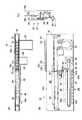
以下、本発明の第1実施形態を図1乃至図3を参照して説明する。図1に示されるように、本実施形態のサンプルラック10には、複数のサンプルカップ12a,…,12jが収容されている。これらサンプルカップ12a,…,12jは、距離Lだけ互いに離間して並設されている。本実施形態では、サンプルラック10の進行方向側の端部のサンプルカップ12aから順に第1、第2、…、第10のサンプルカップ12a,…,12jと称する。第1のサンプルカップ12aの下方には、ICタグ14が内蔵されている。 A first embodiment of the present invention will be described below with reference to FIGS. As shown in FIG. 1, a plurality of
図2(A)に示されるように、サンプルラック10は、サンプルラック搬送装置15の互いに対向する第1及び第2の側壁16a,16b間で、搬送手段としての搬送ベルト18上に配置されている。この搬送ベルト18は、エンドレスベルトであり、ベルト駆動モータ20によって回転作動されて、サンプルラック10を搬送するようになっている。即ち、第1及び第2の側壁16a,16b並びに搬送ベルト18によって、サンプルラック10の搬送経路22が形成されている。また、搬送ベルト18の所定の吸引位置24で、図示しないサンプルプローブにより第1乃至第10のサンプルカップ12a,…,12jのいずれかからサンプルを吸引するようになっている。さらに、サンプルラック10が配置されている搬送ベルト18の下方には、後述するICタグ受信装置25が搬送経路22に沿って延設されている。 As shown in FIG. 2 (A), the
図2(B)に示されるように、サンプルラック搬送装置15は、サンプルラック10を複数の停止位置で停止させるためのストッパ機構26を有している。このストッパ機構26は、ストッパベルト30を有する。このストッパベルト30は、エンドレスベルトであり、ストッパ駆動モータ28によって回転作動される。また、ストッパベルト30には、ストッパ32が連結されている。 As shown in FIG. 2B, the sample
ストッパ32の上部には、サンプルラック10を停止するための爪部34が配設されている。また、ストッパ32の中部には、ベアリング36が配設されている。このベアリング36は、搬送経路22にほぼ平行に延設されているガイド38に押圧されるようになっている。このガイド38は、搬送経路22の終了位置側の端部38aで搬送経路22から離間する方向に延びている(図2(A)参照)。そして、ストッパ32の下部には、フォトインタラプタ40が配設されている。このフォトインタラプタ40は、搬送経路22にほぼ平行に延設されている停止位置板41の複数の切り欠き42a,…,42kを検出可能となっている。停止位置板41には、第1乃至第11の切り欠き42a,…,42kが停止位置板41の長手方向に互いに離間して形成されている。本実施形態では、搬送経路22の開始位置側の端部の切り欠き42aから順に、第1、第2の、…、第11の切り欠き42a,…,42kと称する。 A
ベアリング36及び爪部34は、搬送経路22に接近した図2(C)に示される接近位置と、搬送経路22から離間した離間位置(図示せず)との間で一体的に移動可能となっている。ベアリング36及び爪部34が接近位置にある場合には、ベアリング36はガイド38に押圧されている。また、爪部34の先端部は、第2の側壁16bに形成されている孔43を介して搬送経路22内に突出している。この孔43は、搬送経路22に沿って延設されている。なお、フォトインタラプタ40の搬送経路22に垂直な断面は下向きの凹形状を有しており、この凹形状内に停止位置板41が配置されている。 The
ここで、フォトインタラプタ40が図2(B)に示される第1の切り欠き42aよりも搬送経路22の開始位置側に配置されている場合には、ベアリング36及び爪部34は離間位置に配置されるようになっている。ストッパ32がストッパベルト30によって移動され、フォトインタラプタ40が第1の切り欠き42aを検知すると、ベアリング36及び爪部34は図示しないばねにより接近位置に移動されるようになっている。また、フォトインタラプタ40が第1乃至第11の切り欠き42a,…,42kを検知すると、ストッパベルト30が停止されるようになっている。フォトインタラプタ40が第Nの切り欠き42で停止された場合に、ストッパ32の爪部34によりサンプルラック10が位置決めされ、サンプルラック10の第Nのサンプルカップ12が上記吸引位置24で停止されるようになっている(N=1,2,…,10)。 Here, when the
図3に示されるように、上述したICタグ受信装置25には、アンテナアレー44が配設されている。このアンテナアレー44は、ICタグ受信装置25の長手方向(即ち、搬送経路22(図2(A)参照)の長手方向)に距離Lだけ離間して配置されている第1乃至第10のアンテナ46a,…,46jによって形成されている。本実施形態では、搬送経路22の開始位置側の端部のアンテナ46aから順に第1、第2、…、第10のアンテナ46a,…,46jと称する。これら第1乃至第10のアンテナ46a,…,46jは、サンプルラック10(図1参照)のICタグ14(図1参照)が自身に対面した場合にICタグ14を読み取り可能である。また、第1乃至第10のアンテナ46a,…,46jは、判断部としての受信回路48に接続されている。この受信回路48は、第1乃至第10のアンテナ46a,…,46jの読み取り信号に基づいてサンプルラック10の停止位置を検出し、サンプルラック10が正常な停止位置に位置決めされたか判断するようになっている。 As shown in FIG. 3, an
次に、上記構成の本実施形態のサンプルラック搬送装置15の作用について説明する。ストッパ駆動モータ28によってストッパベルト30を回転作動させ、ストッパ32を移動させる。フォトインタラプタ40が第1の切り欠き42aを検知すると、ストッパベルト30が停止されてストッパ32がその位置で停止される。同時に、ベアリング36及び爪部34が離間位置から接近位置へと移動され、爪部34の先端部が搬送経路22内に突出する。 Next, the operation of the sample
次に、サンプルラック供給部からサンプルラック10を搬送ベルト18上に供給し、搬送ベルト18を回転作動させてサンプルラック10を搬送する。そして、サンプルラック10の先端部は爪部34の先端部に突き当てられて停止され、第1のサンプルカップ12aが吸引位置24で停止される。 Next, the
なお、ICタグ受信装置25はICタグ14の読み取りを試みている。サンプルラック10が正常な停止位置で停止された場合には、ICタグ14は第1のアンテナ46aに対面する。この結果、ICタグ14は第1のアンテナ46aのみによって読み取られる。受信回路48は、第1のアンテナ46aのみから受信信号を受け取った場合には、サンプルラック10が正常な停止位置に位置決めされたと判断する。この場合には、サンプルプローブによって第1のサンプルカップ12aからサンプルを吸引する。 The IC
一方、サンプルラック10が正常な停止位置に位置決めされていない場合には、第1のアンテナ46aはICタグ14に対面しない。従って、第1のアンテナ46aはICタグ14を読み取ることはできない。受信回路48は、第1のアンテナ46a以外のアンテナ46b,…,46jから受信信号を受け取った場合、又は、受信信号を受け取らない場合には、サンプルラック10が正常な停止位置に位置決めされていないと判断する。この場合には、警報を発する等のエラー処理を行う。 On the other hand, when the
第1のサンプルカップ12aからの吸引操作が完了した後、ストッパ32を第2の切り欠き42bまで移動させ、第2のサンプルカップ12bを吸引位置24まで移動させる。サンプルラック10が正常な停止位置に位置決めされた場合には、ICタグ14は第2のアンテナ46bのみによって読み取られる。受信回路48は、第2のアンテナ46bのみから受信信号を受け取った場合には、サンプルラック10が正常な停止位置に位置決めされたと判断する。 After the suction operation from the
以下同様にして、第3乃至第10のサンプルカップ12c,…,12jからサンプルを吸引する。この後、ストッパ32を第11の切り欠き42kまで移動させる。ガイド38の搬送経路22の終了位置側の端部38aにおいて、ベアリング36は端部38aに押圧されて搬送経路22から離間する方向に移動される。この結果、爪部34はベアリング36と共に離間位置へと移動され、爪部34の先端部は搬送経路22から引き抜かれる。この後、サンプルラック10をサンプルラック回収部に回収する。 In the same manner, samples are sucked from the third to
従って、上記構成のものにあっては次の効果を奏する。搬送ベルト18によってサンプルラック10を搬送し、第1乃至第11の切り欠き42a,…,42kに対応する停止位置のいずれかで停止させた後、第1乃至第10のアンテナ46a,…,46jによってICタグ14の読み取りを試みている。そして、受信回路48によって、第1乃至第10のアンテナ46a,…,46jの読み取り結果からサンプルラック10の停止位置が正常な停止位置であるか判断している。このように、ICタグ14を移動させることなく、サンプルラック10の停止位置が正常な停止位置であるか判断することが可能となっている。従って、搬送装置の信頼性の低下や大型化が防止されている。 Therefore, the configuration described above has the following effects. After the
以下、本発明の第1実施形態の変形例を説明する。第1実施形態と同様な機能を有する構成には同一の参照符号を付して説明を省略する。本変形例のICタグ受信装置25には、第1乃至第11のアンテナ46a,…,46kが配設されている。そして、フォトインタラプタ40が第Nの切り欠き42に配置されている場合に、第Nのサンプルカップ12が吸引位置24に配置され、ICタグ14が第Nのアンテナ46と第N+1のアンテナ46との間に配置されるようになっている。また、第Nのアンテナ46と第N+1のアンテナ46とは、ICタグ14が第Nのアンテナ46と第N+1のアンテナ46との間に配置されている場合にICタグ14を読み取ることが可能となっている。 Hereinafter, modifications of the first embodiment of the present invention will be described. Components having the same functions as those of the first embodiment are denoted by the same reference numerals, and description thereof is omitted. The first to
本変形例のサンプルラック搬送装置15によってサンプルラック10を搬送する際には、ストッパ32を第Nの切り欠き42まで移動させ、第Nのサンプルカップ12を吸引位置24まで移動させる。サンプルラック10が正常な停止位置で停止された場合には、ICタグ14は第Nのアンテナ46と第N+1のアンテナ46のみによって読み取られる。受信回路48は、第Nのアンテナ46と第N+1のアンテナ46のみから受信信号を受け取った場合には、サンプルラック10が正常な位置で停止されたと判断する。 When the
図4は、本発明の第2実施形態を示す。第1実施形態と同様な機能を有する構成には、同一の参照符号を付して説明を省略する。本実施形態のICタグ受信装置25は、第1乃至第5のアンテナ46a,…,46eを有する。これら第1乃至第5のアンテナ46a,…,46eは、ICタグ受信装置25の長手方向に距離2Lだけ離間して配置されている。 FIG. 4 shows a second embodiment of the present invention. Components having the same functions as those of the first embodiment are denoted by the same reference numerals, and description thereof is omitted. The IC
フォトインタラプタ40が第2M−1の切り欠き42に配置されている場合には、第2M−1のサンプルカップ12が吸引位置24に配置され、ICタグ14が第Mのアンテナ46に対面されるようになっている(M=1,2,…,5)。この場合には、受信回路48はサンプルラック10が正常な位置で停止されたか判断するようになっている。一方、フォトインタラプタ40が第2Mの切り欠き42に配置されている場合には、第2Mのサンプルカップ12が吸引位置24に配置され、ICタグ14は第1乃至第5のアンテナ46a,…,46eのいずれにも対面されないようになっている。この場合には、受信回路48はサンプルラック10が正常な位置で停止されたか判断しないようになっている。 When the
次に、上記構成の本実施形態のサンプルラック搬送装置15の作用について説明する。サンプルラック搬送装置15によってサンプルラック10を搬送する際、ストッパ32を第2M−1の切り欠き42まで移動させ、第2M−1のサンプルカップ12を吸引位置24まで移動させる。この場合の作用は第1の実施形態と同様である。続いて、ストッパ32を第2Mの切り欠き42まで移動させ、第2Mのサンプルカップ12を吸引位置24まで移動させる。この場合、受信回路48はサンプルラック10が正常な位置で停止されたか判断しない。 Next, the operation of the sample
従って、上記構成のものにあっては次の効果を奏する。フォトインタラプタ40が第2M−1の切り欠き42に配置されている場合に、受信回路48はサンプルラック10が正常な位置で停止されたか判断するようになっている。一方、フォトインタラプタ40が第2Mの切り欠き42に配置されている場合には、受信回路48はサンプルラック10が正常な位置で停止されたか判断しないようになっている。このため、第1実施形態のサンプルラック搬送装置15よりも、短時間で吸引・分注操作を完了することが可能となっている。 Therefore, the configuration described above has the following effects. When the
上述した実施形態では、アンテナアレー44を搬送ベルト18の下方に配置しているが、ICタグ14の配置に応じて、第1又は第2の側壁16a,16bの背面等の他の場所に配置してもよい。 In the above-described embodiment, the
次に、本出願の他の特徴的な技術事項を下記の通り付記する。
記
(付記項1) ICタグを内蔵したサンプルラックの搬送装置において、前記ICタグの受信アンテナを複数並べた、ICタグ読み取り装置を備えたことを特徴とするラック搬送装置。Next, other characteristic technical matters of the present application are appended as follows.
Record
(Additional Item 1) A rack transport apparatus including a plurality of IC tag receiving antennas arranged in a sample rack transport apparatus incorporating an IC tag.
(付記項2) 前記ICタグ読み取り装置の読み取り状態をもとに、サンプルラックの停止位置を検出することを特徴とするラック搬送装置。(Additional Item 2) A rack transport apparatus that detects a stop position of a sample rack based on a reading state of the IC tag reader.
本発明は、装置の信頼性の低下や大型化を招来することなく、サンプルラックが正常な停止位置に位置決めされたか判断可能な、サンプルカップを収容するサンプルラックをサンプル分注位置まで搬送するサンプルラック搬送装置及びサンプルラック搬送方法を提供する。 The present invention is a sample for transporting a sample rack containing a sample cup to a sample dispensing position, in which it can be determined whether the sample rack is positioned at a normal stop position without causing a decrease in reliability or an increase in size of the apparatus. A rack transport device and a sample rack transport method are provided.
10…サンプルラック、12…サンプルカップ、14…ICタグ、15…サンプルラック搬送装置、22…搬送経路、46…アンテナ。 DESCRIPTION OF
Claims (5)
Translated fromJapanese前記サンプルラックを搬送し複数の停止位置で停止させる搬送手段と、
前記サンプルラックの搬送経路の長手方向に互いに離間して設けられ、前記サンプルラックが各々に対応する停止位置にある場合に前記ICタグを読み取り可能な複数のアンテナと、
前記アンテナの読み取り結果から前記サンプルラックが正常な停止位置に位置決めされたか判断する判断部と、
を具備することを特徴とするサンプルラック搬送装置。A sample rack having at least one sample cup for containing a sample and an IC tag;
Transport means for transporting the sample rack and stopping at a plurality of stop positions;
A plurality of antennas that are spaced apart from each other in the longitudinal direction of the transport path of the sample rack and that can read the IC tag when the sample rack is at a corresponding stop position;
A determination unit that determines whether the sample rack is positioned at a normal stop position from the reading result of the antenna;
A sample rack transport apparatus comprising:
サンプルラックの搬送経路の長手方向に互いに離間して設けられている複数のアンテナによってサンプルラックに設けられているICタグの読み取りを試みる工程と、
いずれのアンテナによってICタグが読み取り可能であったかに基づいて、サンプルラックが正常な停止位置に位置決めされたか判断する工程と、
を具備することを特徴とするサンプルラック搬送方法。Transporting the sample rack and stopping it at one of a plurality of stop positions;
Trying to read the IC tag provided in the sample rack by a plurality of antennas provided apart from each other in the longitudinal direction of the transport path of the sample rack;
Determining whether the sample rack is positioned in a normal stop position based on which antenna was able to read the IC tag;
A sample rack transport method comprising the steps of:
Priority Applications (1)
| Application Number | Priority Date | Filing Date | Title |
|---|---|---|---|
| JP2004064529AJP2005249740A (en) | 2004-03-08 | 2004-03-08 | Sample rack conveyer, and sample rack conveying method |
Applications Claiming Priority (1)
| Application Number | Priority Date | Filing Date | Title |
|---|---|---|---|
| JP2004064529AJP2005249740A (en) | 2004-03-08 | 2004-03-08 | Sample rack conveyer, and sample rack conveying method |
Publications (1)
| Publication Number | Publication Date |
|---|---|
| JP2005249740Atrue JP2005249740A (en) | 2005-09-15 |
Family
ID=35030330
Family Applications (1)
| Application Number | Title | Priority Date | Filing Date |
|---|---|---|---|
| JP2004064529APendingJP2005249740A (en) | 2004-03-08 | 2004-03-08 | Sample rack conveyer, and sample rack conveying method |
Country Status (1)
| Country | Link |
|---|---|
| JP (1) | JP2005249740A (en) |
Cited By (55)
| Publication number | Priority date | Publication date | Assignee | Title |
|---|---|---|---|---|
| JP2006308560A (en)* | 2005-03-28 | 2006-11-09 | Sysmex Corp | Transporting apparatus and transporting system |
| JP2011064588A (en)* | 2009-09-17 | 2011-03-31 | Sysmex Corp | Specimen processor |
| JP2013525232A (en)* | 2010-05-07 | 2013-06-20 | ロッシュ ペーファウテー ゲゼルシャフト ミット ベシュレンクテル ハフツンク | System and container carrier for transporting containers between different stations |
| US9187268B2 (en) | 2011-11-04 | 2015-11-17 | Roche Diagnostics Operations, Inc. | Laboratory sample distribution system and corresponding method of operation |
| US9239335B2 (en) | 2011-11-04 | 2016-01-19 | Roche Diagnostics Operations, Inc. | Laboratory sample distribution system, laboratory system and method of operating |
| US9423410B2 (en) | 2014-02-17 | 2016-08-23 | Roche Diagnostics Operations, Inc. | Transport device, sample distribution system, and laboratory automation system |
| US9423411B2 (en) | 2014-02-17 | 2016-08-23 | Roche Diagnostics Operations, Inc. | Transport device, sample distribution system and laboratory automation system |
| US9567167B2 (en) | 2014-06-17 | 2017-02-14 | Roche Diagnostics Operations, Inc. | Laboratory sample distribution system and laboratory automation system |
| US9593970B2 (en) | 2014-09-09 | 2017-03-14 | Roche Diagnostics Operations, Inc. | Laboratory sample distribution system and method for calibrating magnetic sensors |
| US9618525B2 (en) | 2014-10-07 | 2017-04-11 | Roche Diagnostics Operations, Inc. | Module for a laboratory sample distribution system, laboratory sample distribution system and laboratory automation system |
| US9658241B2 (en) | 2014-03-31 | 2017-05-23 | Roche Diagnostics Operations, Inc. | Sample distribution system and laboratory automation system |
| US9664703B2 (en) | 2011-11-04 | 2017-05-30 | Roche Diagnostics Operations, Inc. | Laboratory sample distribution system and corresponding method of operation |
| US9772342B2 (en) | 2014-03-31 | 2017-09-26 | Roche Diagnostics Operations, Inc. | Dispatching device, sample distribution system and laboratory automation system |
| US9791468B2 (en) | 2014-03-31 | 2017-10-17 | Roche Diagnostics Operations, Inc. | Transport device, sample distribution system and laboratory automation system |
| US9810706B2 (en) | 2014-03-31 | 2017-11-07 | Roche Diagnostics Operations, Inc. | Vertical conveying device, laboratory sample distribution system and laboratory automation system |
| US9902572B2 (en) | 2015-10-06 | 2018-02-27 | Roche Diagnostics Operations, Inc. | Method of configuring a laboratory automation system, laboratory sample distribution system and laboratory automation system |
| US9939455B2 (en) | 2014-11-03 | 2018-04-10 | Roche Diagnostics Operations, Inc. | Laboratory sample distribution system and laboratory automation system |
| US9952242B2 (en) | 2014-09-12 | 2018-04-24 | Roche Diagnostics Operations, Inc. | Laboratory sample distribution system and laboratory automation system |
| US9989547B2 (en) | 2014-07-24 | 2018-06-05 | Roche Diagnostics Operations, Inc. | Laboratory sample distribution system and laboratory automation system |
| US10006927B2 (en) | 2015-05-22 | 2018-06-26 | Roche Diagnostics Operations, Inc. | Method of operating a laboratory automation system and a laboratory automation system |
| US10012666B2 (en) | 2014-03-31 | 2018-07-03 | Roche Diagnostics Operations, Inc. | Sample distribution system and laboratory automation system |
| US10094843B2 (en) | 2015-03-23 | 2018-10-09 | Roche Diagnostics Operations, Inc. | Laboratory sample distribution system and laboratory automation system |
| US10119982B2 (en) | 2015-03-16 | 2018-11-06 | Roche Diagnostics Operations, Inc. | Transport carrier, laboratory cargo distribution system, and laboratory automation system |
| US10160609B2 (en) | 2015-10-13 | 2018-12-25 | Roche Diagnostics Operations, Inc. | Laboratory sample distribution system and laboratory automation system |
| US10175259B2 (en) | 2015-09-01 | 2019-01-08 | Roche Diagnostics Operations, Inc. | Laboratory cargo distribution system, laboratory automation system and method of operating a laboratory cargo distribution system |
| US10197586B2 (en) | 2015-10-06 | 2019-02-05 | Roche Diagnostics Operations, Inc. | Method of determining a handover position and laboratory automation system |
| US10197555B2 (en) | 2016-06-21 | 2019-02-05 | Roche Diagnostics Operations, Inc. | Method of setting a handover position and laboratory automation system |
| US10228384B2 (en) | 2015-10-14 | 2019-03-12 | Roche Diagnostics Operations, Inc. | Method of rotating a sample container carrier, laboratory sample distribution system and laboratory automation system |
| US10239708B2 (en) | 2014-09-09 | 2019-03-26 | Roche Diagnostics Operations, Inc. | Laboratory sample distribution system and laboratory automation system |
| US10352953B2 (en) | 2015-05-22 | 2019-07-16 | Roche Diagnostics Operations, Inc. | Method of operating a laboratory sample distribution system, laboratory sample distribution system and a laboratory automation system |
| US10416183B2 (en) | 2016-12-01 | 2019-09-17 | Roche Diagnostics Operations, Inc. | Laboratory sample distribution system and laboratory automation system |
| US10436808B2 (en) | 2016-12-29 | 2019-10-08 | Roche Diagnostics Operations, Inc. | Laboratory sample distribution system and laboratory automation system |
| US10495657B2 (en) | 2017-01-31 | 2019-12-03 | Roche Diagnostics Operations, Inc. | Laboratory sample distribution system and laboratory automation system |
| US10509049B2 (en) | 2014-09-15 | 2019-12-17 | Roche Diagnostics Operations, Inc. | Method of operating a laboratory sample distribution system, laboratory sample distribution system and laboratory automation system |
| US10520520B2 (en) | 2016-02-26 | 2019-12-31 | Roche Diagnostics Operations, Inc. | Transport device with base plate modules |
| US10564170B2 (en) | 2015-07-22 | 2020-02-18 | Roche Diagnostics Operations, Inc. | Sample container carrier, laboratory sample distribution system and laboratory automation system |
| US10578632B2 (en) | 2016-02-26 | 2020-03-03 | Roche Diagnostics Operations, Inc. | Transport device unit for a laboratory sample distribution system |
| US10605819B2 (en) | 2016-02-26 | 2020-03-31 | Roche Diagnostics Operations, Inc. | Transport device having a tiled driving surface |
| US10962557B2 (en) | 2017-07-13 | 2021-03-30 | Roche Diagnostics Operations, Inc. | Method of operating a laboratory sample distribution system, laboratory sample distribution system and laboratory automation system |
| US10989726B2 (en) | 2016-06-09 | 2021-04-27 | Roche Diagnostics Operations, Inc. | Laboratory sample distribution system and method of operating a laboratory sample distribution system |
| US10989725B2 (en) | 2017-06-02 | 2021-04-27 | Roche Diagnostics Operations, Inc. | Method of operating a laboratory sample distribution system, laboratory sample distribution system, and laboratory automation system |
| US10996233B2 (en) | 2016-06-03 | 2021-05-04 | Roche Diagnostics Operations, Inc. | Laboratory sample distribution system and laboratory automation system |
| US11092613B2 (en) | 2015-05-22 | 2021-08-17 | Roche Diagnostics Operations, Inc. | Method of operating a laboratory sample distribution system, laboratory sample distribution system and laboratory automation system |
| US11110463B2 (en) | 2017-09-13 | 2021-09-07 | Roche Diagnostics Operations, Inc. | Sample container carrier, laboratory sample distribution system and laboratory automation system |
| US11112421B2 (en) | 2016-08-04 | 2021-09-07 | Roche Diagnostics Operations, Inc. | Laboratory sample distribution system and laboratory automation system |
| US11110464B2 (en) | 2017-09-13 | 2021-09-07 | Roche Diagnostics Operations, Inc. | Sample container carrier, laboratory sample distribution system and laboratory automation system |
| US11204361B2 (en) | 2017-02-03 | 2021-12-21 | Roche Diagnostics Operations, Inc. | Laboratory automation system |
| US11226348B2 (en) | 2015-07-02 | 2022-01-18 | Roche Diagnostics Operations, Inc. | Storage module, method of operating a laboratory automation system and laboratory automation system |
| US11709171B2 (en) | 2018-03-16 | 2023-07-25 | Roche Diagnostics Operations, Inc. | Laboratory system, laboratory sample distribution system and laboratory automation system |
| US11747356B2 (en) | 2020-12-21 | 2023-09-05 | Roche Diagnostics Operations, Inc. | Support element for a modular transport plane, modular transport plane, and laboratory distribution system |
| US11971420B2 (en) | 2018-03-07 | 2024-04-30 | Roche Diagnostics Operations, Inc. | Method of operating a laboratory sample distribution system, laboratory sample distribution system and laboratory automation system |
| JP7486383B2 (en) | 2019-09-05 | 2024-05-17 | エフ. ホフマン-ラ ロシュ アーゲー | Method and system for locating a carrier on a laboratory transport system - Patents.com |
| US12000851B2 (en) | 2020-07-15 | 2024-06-04 | Roche Diagnostics Operations, Inc. | Laboratory sample distribution system and method for operating the same |
| US12000850B2 (en) | 2020-06-19 | 2024-06-04 | Roche Diagnostics Operations, Inc. | Laboratory sample distribution system and corresponding method of operation |
| US12429491B2 (en) | 2020-11-23 | 2025-09-30 | Roche Diagnostics Operations, Inc. | Laboratory sample distribution system and laboratory automation system |
- 2004
- 2004-03-08JPJP2004064529Apatent/JP2005249740A/enactivePending
Cited By (68)
| Publication number | Priority date | Publication date | Assignee | Title |
|---|---|---|---|---|
| JP2006308560A (en)* | 2005-03-28 | 2006-11-09 | Sysmex Corp | Transporting apparatus and transporting system |
| JP2011064588A (en)* | 2009-09-17 | 2011-03-31 | Sysmex Corp | Specimen processor |
| JP2013525232A (en)* | 2010-05-07 | 2013-06-20 | ロッシュ ペーファウテー ゲゼルシャフト ミット ベシュレンクテル ハフツンク | System and container carrier for transporting containers between different stations |
| KR20130095178A (en)* | 2010-05-07 | 2013-08-27 | 로쉐 피브이티 게엠베하 | System for transporting containers between different stations, and the container carrier |
| US9969570B2 (en) | 2010-05-07 | 2018-05-15 | Roche Diagnostics Operations, Inc. | System for transporting containers between different stations and a container carrier |
| KR101721390B1 (en) | 2010-05-07 | 2017-03-29 | 에프. 호프만-라 로슈 아게 | System for transporting containers between different stations, and the container carrier |
| KR101592877B1 (en) | 2010-05-07 | 2016-02-11 | 로쉐 피브이티 게엠베하 | System for transporting containers between different stations, and the container carrier |
| KR20160020580A (en)* | 2010-05-07 | 2016-02-23 | 로쉐 피브이티 게엠베하 | System for transporting containers between different stations, and the container carrier |
| US9575086B2 (en) | 2011-11-04 | 2017-02-21 | Roche Diagnostics Operations, Inc. | Laboratory sample distribution system, laboratory system and method of operating |
| JP2016166890A (en)* | 2011-11-04 | 2016-09-15 | エフ.ホフマン−ラ ロシュ アーゲーF. Hoffmann−La Roche Aktiengesellschaft | Laboratory sample distribution system and corresponding method of operation |
| US10450151B2 (en) | 2011-11-04 | 2019-10-22 | Roche Diagnostics Operations, Inc. | Laboratory sample distribution system and corresponding method of operation |
| US10126317B2 (en) | 2011-11-04 | 2018-11-13 | Roche Diagnostics Operations, Inc. | Laboratory sample distribution system, laboratory system and method of operating |
| US9598243B2 (en) | 2011-11-04 | 2017-03-21 | Roche Diagnostics Operations, Inc. | Laboratory sample distribution system and corresponding method of operation |
| US9239335B2 (en) | 2011-11-04 | 2016-01-19 | Roche Diagnostics Operations, Inc. | Laboratory sample distribution system, laboratory system and method of operating |
| US10031150B2 (en) | 2011-11-04 | 2018-07-24 | Roche Diagnostics Operations, Inc. | Laboratory sample distribution system, laboratory system and method of operating |
| US9187268B2 (en) | 2011-11-04 | 2015-11-17 | Roche Diagnostics Operations, Inc. | Laboratory sample distribution system and corresponding method of operation |
| US9664703B2 (en) | 2011-11-04 | 2017-05-30 | Roche Diagnostics Operations, Inc. | Laboratory sample distribution system and corresponding method of operation |
| US9423411B2 (en) | 2014-02-17 | 2016-08-23 | Roche Diagnostics Operations, Inc. | Transport device, sample distribution system and laboratory automation system |
| US9423410B2 (en) | 2014-02-17 | 2016-08-23 | Roche Diagnostics Operations, Inc. | Transport device, sample distribution system, and laboratory automation system |
| US9791468B2 (en) | 2014-03-31 | 2017-10-17 | Roche Diagnostics Operations, Inc. | Transport device, sample distribution system and laboratory automation system |
| US9658241B2 (en) | 2014-03-31 | 2017-05-23 | Roche Diagnostics Operations, Inc. | Sample distribution system and laboratory automation system |
| US9810706B2 (en) | 2014-03-31 | 2017-11-07 | Roche Diagnostics Operations, Inc. | Vertical conveying device, laboratory sample distribution system and laboratory automation system |
| US9772342B2 (en) | 2014-03-31 | 2017-09-26 | Roche Diagnostics Operations, Inc. | Dispatching device, sample distribution system and laboratory automation system |
| US10012666B2 (en) | 2014-03-31 | 2018-07-03 | Roche Diagnostics Operations, Inc. | Sample distribution system and laboratory automation system |
| US9567167B2 (en) | 2014-06-17 | 2017-02-14 | Roche Diagnostics Operations, Inc. | Laboratory sample distribution system and laboratory automation system |
| US9989547B2 (en) | 2014-07-24 | 2018-06-05 | Roche Diagnostics Operations, Inc. | Laboratory sample distribution system and laboratory automation system |
| US9593970B2 (en) | 2014-09-09 | 2017-03-14 | Roche Diagnostics Operations, Inc. | Laboratory sample distribution system and method for calibrating magnetic sensors |
| US10239708B2 (en) | 2014-09-09 | 2019-03-26 | Roche Diagnostics Operations, Inc. | Laboratory sample distribution system and laboratory automation system |
| US9952242B2 (en) | 2014-09-12 | 2018-04-24 | Roche Diagnostics Operations, Inc. | Laboratory sample distribution system and laboratory automation system |
| US10509049B2 (en) | 2014-09-15 | 2019-12-17 | Roche Diagnostics Operations, Inc. | Method of operating a laboratory sample distribution system, laboratory sample distribution system and laboratory automation system |
| US9618525B2 (en) | 2014-10-07 | 2017-04-11 | Roche Diagnostics Operations, Inc. | Module for a laboratory sample distribution system, laboratory sample distribution system and laboratory automation system |
| US9939455B2 (en) | 2014-11-03 | 2018-04-10 | Roche Diagnostics Operations, Inc. | Laboratory sample distribution system and laboratory automation system |
| US10119982B2 (en) | 2015-03-16 | 2018-11-06 | Roche Diagnostics Operations, Inc. | Transport carrier, laboratory cargo distribution system, and laboratory automation system |
| US10094843B2 (en) | 2015-03-23 | 2018-10-09 | Roche Diagnostics Operations, Inc. | Laboratory sample distribution system and laboratory automation system |
| US11092613B2 (en) | 2015-05-22 | 2021-08-17 | Roche Diagnostics Operations, Inc. | Method of operating a laboratory sample distribution system, laboratory sample distribution system and laboratory automation system |
| US10006927B2 (en) | 2015-05-22 | 2018-06-26 | Roche Diagnostics Operations, Inc. | Method of operating a laboratory automation system and a laboratory automation system |
| US10352953B2 (en) | 2015-05-22 | 2019-07-16 | Roche Diagnostics Operations, Inc. | Method of operating a laboratory sample distribution system, laboratory sample distribution system and a laboratory automation system |
| US11226348B2 (en) | 2015-07-02 | 2022-01-18 | Roche Diagnostics Operations, Inc. | Storage module, method of operating a laboratory automation system and laboratory automation system |
| US10564170B2 (en) | 2015-07-22 | 2020-02-18 | Roche Diagnostics Operations, Inc. | Sample container carrier, laboratory sample distribution system and laboratory automation system |
| US10175259B2 (en) | 2015-09-01 | 2019-01-08 | Roche Diagnostics Operations, Inc. | Laboratory cargo distribution system, laboratory automation system and method of operating a laboratory cargo distribution system |
| US10197586B2 (en) | 2015-10-06 | 2019-02-05 | Roche Diagnostics Operations, Inc. | Method of determining a handover position and laboratory automation system |
| US9902572B2 (en) | 2015-10-06 | 2018-02-27 | Roche Diagnostics Operations, Inc. | Method of configuring a laboratory automation system, laboratory sample distribution system and laboratory automation system |
| US10160609B2 (en) | 2015-10-13 | 2018-12-25 | Roche Diagnostics Operations, Inc. | Laboratory sample distribution system and laboratory automation system |
| US10228384B2 (en) | 2015-10-14 | 2019-03-12 | Roche Diagnostics Operations, Inc. | Method of rotating a sample container carrier, laboratory sample distribution system and laboratory automation system |
| US10578632B2 (en) | 2016-02-26 | 2020-03-03 | Roche Diagnostics Operations, Inc. | Transport device unit for a laboratory sample distribution system |
| US10948508B2 (en) | 2016-02-26 | 2021-03-16 | Roche Diagnostics Operations, Inc. | Transport device unit for a laboratory sample distribution system |
| US10520520B2 (en) | 2016-02-26 | 2019-12-31 | Roche Diagnostics Operations, Inc. | Transport device with base plate modules |
| US10605819B2 (en) | 2016-02-26 | 2020-03-31 | Roche Diagnostics Operations, Inc. | Transport device having a tiled driving surface |
| US10996233B2 (en) | 2016-06-03 | 2021-05-04 | Roche Diagnostics Operations, Inc. | Laboratory sample distribution system and laboratory automation system |
| US10989726B2 (en) | 2016-06-09 | 2021-04-27 | Roche Diagnostics Operations, Inc. | Laboratory sample distribution system and method of operating a laboratory sample distribution system |
| US10197555B2 (en) | 2016-06-21 | 2019-02-05 | Roche Diagnostics Operations, Inc. | Method of setting a handover position and laboratory automation system |
| US11112421B2 (en) | 2016-08-04 | 2021-09-07 | Roche Diagnostics Operations, Inc. | Laboratory sample distribution system and laboratory automation system |
| US10416183B2 (en) | 2016-12-01 | 2019-09-17 | Roche Diagnostics Operations, Inc. | Laboratory sample distribution system and laboratory automation system |
| US10436808B2 (en) | 2016-12-29 | 2019-10-08 | Roche Diagnostics Operations, Inc. | Laboratory sample distribution system and laboratory automation system |
| US10495657B2 (en) | 2017-01-31 | 2019-12-03 | Roche Diagnostics Operations, Inc. | Laboratory sample distribution system and laboratory automation system |
| US11204361B2 (en) | 2017-02-03 | 2021-12-21 | Roche Diagnostics Operations, Inc. | Laboratory automation system |
| US10989725B2 (en) | 2017-06-02 | 2021-04-27 | Roche Diagnostics Operations, Inc. | Method of operating a laboratory sample distribution system, laboratory sample distribution system, and laboratory automation system |
| US10962557B2 (en) | 2017-07-13 | 2021-03-30 | Roche Diagnostics Operations, Inc. | Method of operating a laboratory sample distribution system, laboratory sample distribution system and laboratory automation system |
| US11110463B2 (en) | 2017-09-13 | 2021-09-07 | Roche Diagnostics Operations, Inc. | Sample container carrier, laboratory sample distribution system and laboratory automation system |
| US11110464B2 (en) | 2017-09-13 | 2021-09-07 | Roche Diagnostics Operations, Inc. | Sample container carrier, laboratory sample distribution system and laboratory automation system |
| US11971420B2 (en) | 2018-03-07 | 2024-04-30 | Roche Diagnostics Operations, Inc. | Method of operating a laboratory sample distribution system, laboratory sample distribution system and laboratory automation system |
| US11709171B2 (en) | 2018-03-16 | 2023-07-25 | Roche Diagnostics Operations, Inc. | Laboratory system, laboratory sample distribution system and laboratory automation system |
| JP7486383B2 (en) | 2019-09-05 | 2024-05-17 | エフ. ホフマン-ラ ロシュ アーゲー | Method and system for locating a carrier on a laboratory transport system - Patents.com |
| US12196772B2 (en) | 2019-09-05 | 2025-01-14 | Roche Diagnostics Operations, Inc. | Method and system to localize a carrier on a laboratory transport system |
| US12000850B2 (en) | 2020-06-19 | 2024-06-04 | Roche Diagnostics Operations, Inc. | Laboratory sample distribution system and corresponding method of operation |
| US12000851B2 (en) | 2020-07-15 | 2024-06-04 | Roche Diagnostics Operations, Inc. | Laboratory sample distribution system and method for operating the same |
| US12429491B2 (en) | 2020-11-23 | 2025-09-30 | Roche Diagnostics Operations, Inc. | Laboratory sample distribution system and laboratory automation system |
| US11747356B2 (en) | 2020-12-21 | 2023-09-05 | Roche Diagnostics Operations, Inc. | Support element for a modular transport plane, modular transport plane, and laboratory distribution system |
Similar Documents
| Publication | Publication Date | Title |
|---|---|---|
| JP2005249740A (en) | Sample rack conveyer, and sample rack conveying method | |
| US8329102B2 (en) | Conveying device and sample processing method | |
| EP0313093B1 (en) | Ic card reader / writer | |
| CN107211563B (en) | Setup change adjustment support device, component mounting apparatus, setup change adjustment support method, and storage medium | |
| JP7106365B2 (en) | Card reader and foreign object detection method | |
| CN111051891B (en) | Connection module and interference avoidance method | |
| JP4064913B2 (en) | Card reader | |
| US20190163938A1 (en) | Control method of card reader and card reader | |
| JP2008276484A (en) | Card issuing device | |
| US7255524B2 (en) | Substrate cassette mapper | |
| JP3708054B2 (en) | Specimen rack horizontal transfer device and sample rack supply device | |
| KR20160091737A (en) | A Board Loading and Transport Device and Transfer System including thereof | |
| KR101694469B1 (en) | A Board Loading and Transport Device | |
| JP2007184309A (en) | Transport machine, mounting machine, printing machine and inspection machine | |
| JP2000114350A (en) | Method and device for detecting wafer | |
| JP2002319795A (en) | Plate work transfer device | |
| JP7219557B2 (en) | Card reader and foreign object detection method | |
| JP3158522B2 (en) | Media processing device | |
| JP2000137771A (en) | Card reader | |
| US20220207248A1 (en) | Card reader and transaction apparatus | |
| JP2018100177A (en) | Tray type carrying apparatus | |
| JP2010039681A (en) | Magnetic card issuing machine and magnetic card supply unit | |
| JP4878559B2 (en) | Print media handling device | |
| JP2003294766A (en) | Rack conveying device | |
| JP4602182B2 (en) | Cuvette catching device |
Legal Events
| Date | Code | Title | Description |
|---|---|---|---|
| A621 | Written request for application examination | Effective date:20070308 Free format text:JAPANESE INTERMEDIATE CODE: A621 | |
| A977 | Report on retrieval | Free format text:JAPANESE INTERMEDIATE CODE: A971007 Effective date:20090423 | |
| A131 | Notification of reasons for refusal | Effective date:20090512 Free format text:JAPANESE INTERMEDIATE CODE: A131 | |
| A02 | Decision of refusal | Free format text:JAPANESE INTERMEDIATE CODE: A02 Effective date:20091006 | |
| A711 | Notification of change in applicant | Free format text:JAPANESE INTERMEDIATE CODE: A711 Effective date:20100210 |