JP2005246863A - Inkjet printer - Google Patents
Inkjet printerDownload PDFInfo
- Publication number
- JP2005246863A JP2005246863AJP2004062611AJP2004062611AJP2005246863AJP 2005246863 AJP2005246863 AJP 2005246863AJP 2004062611 AJP2004062611 AJP 2004062611AJP 2004062611 AJP2004062611 AJP 2004062611AJP 2005246863 AJP2005246863 AJP 2005246863A
- Authority
- JP
- Japan
- Prior art keywords
- recording head
- recording
- tube
- roller
- ink
- Prior art date
- Legal status (The legal status is an assumption and is not a legal conclusion. Google has not performed a legal analysis and makes no representation as to the accuracy of the status listed.)
- Granted
Links
- 238000011144upstream manufacturingMethods0.000claimsdescription6
- 238000009434installationMethods0.000claimsdescription5
- 238000007599dischargingMethods0.000claimsdescription2
- 239000000976inkSubstances0.000description59
- 230000005484gravityEffects0.000description3
- 238000000034methodMethods0.000description3
- 239000003086colorantSubstances0.000description2
- 239000011521glassSubstances0.000description2
- 239000011347resinSubstances0.000description2
- 229920005989resinPolymers0.000description2
- 230000015572biosynthetic processEffects0.000description1
- 239000007788liquidSubstances0.000description1
- 239000002184metalSubstances0.000description1
- 238000012986modificationMethods0.000description1
- 230000004048modificationEffects0.000description1
Images


Landscapes
- Ink Jet (AREA)
Abstract
Translated fromJapaneseDescription
Translated fromJapanese本発明は、記録ヘッドからインクを吐出して被記録媒体に画像を形成するインクジェットプリンタに係り、特に記録ヘッドを被記録媒体の幅方向に往復移動させると共に、上記記録ヘッドにチューブを通してインクを供給して被記録媒体に画像を形成するシリアルタイプのインクジェットプリンタに関する。 The present invention relates to an ink jet printer that discharges ink from a recording head to form an image on a recording medium, and in particular, reciprocates the recording head in the width direction of the recording medium and supplies ink to the recording head through a tube. The present invention relates to a serial type ink jet printer that forms an image on a recording medium.
従来のインクジェットプリンタでは、記録ヘッドと別体にインクを保持するインク保持部を設け、そのインク保持部からチューブを通して記録ヘッドにインクを供給するようにしている。この構成では、記録ヘッドにインク保持部を一体に設けた構成に比べて記録ヘッドを容易に小型化することができる。このような構成をシリアルタイプのインクジェットプリンタに採用すれば、記録ヘッドを小型化することによってキャリッジモータの負荷を軽減し、そのキャリッジモータも小型化することができる。 In a conventional ink jet printer, an ink holding unit that holds ink is provided separately from the recording head, and ink is supplied from the ink holding unit to the recording head through a tube. In this configuration, the recording head can be easily downsized as compared with the configuration in which the ink holding portion is integrally provided in the recording head. If such a configuration is employed in a serial type ink jet printer, the load on the carriage motor can be reduced by downsizing the recording head, and the carriage motor can be downsized.
このようにインク保持部からチューブを通して記録ヘッドにインクを供給する場合、記録ヘッドにチューブを取り付ける方法としては、チューブを記録ヘッドの上面(プラテンと反対側の面)から突出させる方法と、記録ヘッドの移動方向側端面から突出させる方法とが考えられる。モバイルプリンタとしてコンパクト化する場合など、インクジェットプリンタを薄型化する要請が強い場合は、チューブをヘッドの移動方向側端面から突出させるのが望ましい。 When ink is supplied to the recording head from the ink holding portion through the tube in this way, the tube is attached to the recording head by a method of projecting the tube from the upper surface (surface opposite to the platen) of the recording head, and the recording head. It is conceivable to project from the end surface on the moving direction side. When there is a strong demand for reducing the thickness of an inkjet printer, such as when making it compact as a mobile printer, it is desirable to project the tube from the end surface of the head in the moving direction.
上記のようなインクジェットプリンタには、例えば特許文献1に開示されたものがある。このインクジェットプリンタは、記録ヘッドにインクを供給するチューブが2本づつ記録ヘッドの移動方向両側端面からそれぞれ記録ヘッドの移動方向に対して傾いた方向に突出している。
ところで、上記特許文献1に開示された発明のように、チューブを記録ヘッドの移動方向側端面から突出させると、記録ヘッドの移動時、その記録ヘッドの移動範囲内のプラテン上方においてチューブが撓むことになる。 By the way, as in the invention disclosed in
このため、被記録媒体の搬送時に被記録媒体がプラテンにおいてジャムし、そのジャムした被記録媒体を取り除こうとした場合には、上記撓んだチューブが邪魔になり、ジャム除去処理がしにくいという可能性があった。 For this reason, when the recording medium is jammed on the platen when the recording medium is transported, and the jammed recording medium is to be removed, the above-described bent tube becomes an obstacle and it is difficult to remove the jam. There was sex.
また、記録ヘッドの被記録媒体の搬送方向に対して上流側に一対の搬送ローラを配置すると共に、記録ヘッドの被記録媒体の搬送方向に対して下流側に一対の排出ローラを配置した構造のインクジェットプリンタにおいては、さらなる薄型化が要請されている。 In addition, a pair of conveyance rollers is arranged upstream of the recording medium conveyance direction of the recording head, and a pair of discharge rollers is arranged downstream of the recording head conveyance direction of the recording medium. Inkjet printers are required to be thinner.
そこで本発明は、記録ヘッドの下方において被記録媒体がジャムした場合でも、そのジャムした被記録媒体を容易に除去可能なインクジェットプリンタを提供することを目的とする。 Therefore, an object of the present invention is to provide an ink jet printer that can easily remove a jammed recording medium even when the recording medium is jammed under a recording head.
上記目的を達成するため、請求項1に記載の発明は、インクを吐出して被記録媒体に画像を形成する記録ヘッドと、該記録ヘッドとは別体に設けられたインク保持部から前記記録ヘッドにインクを供給するチューブと、前記被記録媒体の幅方向に前記記録ヘッドの移動を案内する案内部と、前記案内部に沿って前記記録ヘッドを往復移動させるヘッド移動手段と、前記案内部に対して直交方向に前記被記録媒体を搬送する一対の搬送ローラと、前記記録ヘッドにより画像が形成された被記録媒体を排出する一対の排出ローラと、を備えたインクジェットプリンタであって、前記チューブは、前記記録ヘッドの移動方向側端面であって、前記記録ヘッドの前記被記録媒体の搬送方向下流側に接続したことを特徴としている。 In order to achieve the above object, the invention described in
請求項2に記載の発明は、上記構成のインクジェットプリンタにおいて、前記案内部は、一対のガイドレールであって、前記記録ヘッドに対する前記チューブの接続側に位置するガイドレールを、断面L字状に形成したことを特徴としている。 According to a second aspect of the present invention, in the ink jet printer having the above configuration, the guide portion is a pair of guide rails, and the guide rail located on the connection side of the tube with respect to the recording head has an L-shaped cross section. It is characterized by the formation.
請求項3に記載の発明は、上記構成のインクジェットプリンタにおいて、前記ヘッド移動手段は、前記記録ヘッドに対する前記チューブの接続側に配置したことを特徴としている。 According to a third aspect of the present invention, in the ink jet printer having the above-described configuration, the head moving means is disposed on a connection side of the tube with respect to the recording head.
請求項4に記載の発明は、上記構成のインクジェットプリンタにおいて、前記一対の搬送ローラを前記記録ヘッドの前記被記録媒体の搬送方向上流側に配置し、これらの搬送ローラのうち前記記録ヘッド側に位置するローラを駆動ローラとした場合、前記記録ヘッドにおいて前記チューブの接続側と対向する側に位置するガイドレールを、プリンタ設置面に対して平行に形成したことを特徴としている。 According to a fourth aspect of the present invention, in the ink jet printer having the above-described configuration, the pair of transport rollers is disposed on the upstream side of the recording head in the transport direction of the recording medium, and among the transport rollers, on the recording head side. When the positioned roller is a driving roller, a guide rail positioned on the side of the recording head facing the tube connection side is formed in parallel to the printer installation surface.
請求項5に記載の発明は、上記構成のインクジェットプリンタにおいて、前記断面L字状に形成したガイドレールの下方に前記一対の排出ローラを配置し、これらの排出ローラのうち前記L字状に形成したガイドレール側に位置するローラと対向するローラを駆動ローラとしたことを特徴としている。 According to a fifth aspect of the present invention, in the ink jet printer having the above-described configuration, the pair of discharge rollers is disposed below the guide rail formed in the L-shaped cross section, and the L-shaped among the discharge rollers is formed. The roller facing the roller located on the guide rail side is a drive roller.
請求項1に記載の発明によれば、チューブを、記録ヘッドの移動方向側端面であって、記録ヘッドの被記録媒体の搬送方向下流側に接続したことにより、記録ヘッドを案内部に沿って往復移動させているとき、チューブが記録ヘッドの移動範囲内に位置することがなくなる。よって、被記録媒体の搬送時に記録ヘッドの下方において被記録媒体がジャムし、そのジャムした被記録媒体を取り除く場合でも、除去処理の邪魔になるチューブが位置することがないので、容易にジャム除去処理を行うことができる。その結果、使い勝手が良好なインクジェットプリンタを提供することができる。 According to the first aspect of the present invention, the recording head is moved along the guide portion by connecting the tube to the downstream side in the transport direction of the recording medium of the recording head on the moving head side end surface of the recording head. When reciprocating, the tube is not positioned within the moving range of the recording head. Therefore, when the recording medium is transported, the recording medium is jammed under the recording head, and even when the jammed recording medium is removed, a tube that does not obstruct the removal process is not located, so that the jam can be easily removed. Processing can be performed. As a result, it is possible to provide an ink jet printer that is easy to use.
請求項2に記載の発明によれば、記録ヘッドに対するチューブの接続側に位置するガイドレールを断面L字状に形成したことにより、プリンタの重心に対する記録ヘッドおよびヘッド移動手段の重量バランスが良好になり、モーメントが小さくなるため、記録ヘッドのガタつきが防止され、被記録媒体に正確な画像を形成することができる。そして、ガイドレールを断面L字状に形成したので、ガイドレールの成形が容易になり、案内手段の低価格化を図ることができる。 According to the second aspect of the present invention, the guide rail located on the connection side of the tube to the recording head is formed in an L-shaped cross section, so that the weight balance of the recording head and the head moving means with respect to the center of gravity of the printer is good. As a result, the moment is reduced, and the play of the recording head is prevented, and an accurate image can be formed on the recording medium. Since the guide rail is formed in an L-shaped cross section, the guide rail can be easily formed, and the cost of the guide means can be reduced.
請求項3に記載の発明によれば、ヘッド移動手段を記録ヘッドに対するチューブの接続側に配置したことにより、重量バランスが良好になり、モーメントが小さくなるため、記録ヘッドのガタつきが防止され、被記録媒体に正確な画像を形成することができる。 According to the invention described in
請求項4に記載の発明によれば、一対の搬送ローラを記録ヘッドの被記録媒体の搬送方向上流側に配置し、これらの搬送ローラのうち記録ヘッド側に位置するローラを駆動ローラとした場合、記録ヘッドにおいてチューブの接続側と対向する側に位置するガイドレールを、プリンタ設置面に対して平行に形成したことにより、駆動ローラを逆にした場合に比べ、プリンタの高さを低くすることができるため、プリンタを薄型化することができる。 According to the fourth aspect of the present invention, the pair of transport rollers is arranged on the upstream side of the recording head in the transport direction of the recording medium, and among these transport rollers, the roller positioned on the recording head side is a driving roller The guide rail located on the side of the recording head that faces the tube connection side is formed parallel to the printer installation surface, so that the height of the printer can be reduced compared to when the drive roller is reversed. Therefore, the printer can be thinned.
請求項5に記載の発明によれば、断面L字状に形成したガイドレールの下方に一対の排出ローラを配置し、これらの排出ローラのうちL字状に形成したガイドレール側に位置するローラと対向するローラを駆動ローラとしたことにより、駆動ローラを逆にした場合に比べ、プリンタの高さを低くすることができるため、プリンタを薄型化することができる。 According to invention of
以下、本発明の実施形態について図面に基づいて説明する。 Hereinafter, embodiments of the present invention will be described with reference to the drawings.
本実施の形態は、プリンタ機能、コピー機能、スキャナ機能、ファクシミリ機能および電話機能などを備えた多機能装置に本発明を適用した場合のものである。また、本実施形態では、図1に示すように被記録媒体としての記録紙の搬送方向上流側を後側とし、記録紙の搬送方向下流側を前側とすると共に、給紙カセットを挿入する開口部に正対して右側、左側としている。 In this embodiment, the present invention is applied to a multi-function device having a printer function, a copy function, a scanner function, a facsimile function, a telephone function, and the like. In the present embodiment, as shown in FIG. 1, the upstream side in the conveyance direction of the recording paper as the recording medium is the rear side, the downstream side in the conveyance direction of the recording paper is the front side, and the opening for inserting the paper feed cassette The right side and the left side are directly facing the part.
図1に示すように、多機能装置1には、上側にコピー機能(スキャナ機能)とファクシミリ機能のための原稿読み取り装置2が設けられ、その原稿読み取り装置2の下側全体にプリンタ機能を実現するインクジェットプリンタ3が設けられている。 As shown in FIG. 1, the
原稿読み取り装置2は、図示しないが、後端部において水平軸により上下揺動可能に構成された上部カバー2aを上側に開けると、原稿を載置する載置用ガラスが設けられ、その載置用ガラスの下側に原稿読み取り用のイメージスキャナ装置が設けられている。 Although not shown, the
図2に示すように、インクジェットプリンタ3は、その下部に給紙カセット4を備える。この給紙カセット4は、その開口部5から前後方向に出し入れ自在に挿入される。給紙カセット4には、記録紙Aを積載収納する凹部4aが設けられ、給紙カセット4が挿入されると、凹部4a内の記録紙Aは後部に配置される。給紙カセット4の前部には、後述するように記録された記録紙Aを受けるためのトレー4bが形成されている。 As shown in FIG. 2, the
図2に示すように、給紙カセット4の上方には、給紙装置6が配置され、この給紙装置6の上部には記録部7が配置されている。また、給紙装置6は、給紙カセット4内の記録紙Aを一枚づつ分離して記録部7へと送り出す給紙ローラ6aを備える。そして、給紙装置6の記録紙Aの搬送方向下流側には、給紙カセット4の後部から記録部7へと記録紙Aを案内する案内路8が湾曲して形成されている。 As shown in FIG. 2, a
この案内路8の記録紙Aの搬送方向下流側には、図3に示すように搬送ローラ9とニップローラ10が配設され、これら搬送ローラ9とニップローラ10とで本発明の一対の搬送ローラを構成している。そして、ニップローラ10は、搬送ローラ9の下方に配置され、搬送ローラ9との間に記録紙Aを押圧挟持する一方、搬送ローラ9は駆動ローラとなる。 As shown in FIG. 3, a
また、搬送ローラ9およびニップローラ10の記録紙Aの搬送方向下流側には、上記記録部7が配設され、この記録部7の下部にプラテン11が配置され、このプラテン11上に記録紙Aが搬送されたときに記録部7の後述する記録ヘッドにより画像が形成される。 Further, the
さらに、記録部7の記録紙Aの搬送方向下流側には、上記画像が形成された記録紙Aを排出するための拍車ローラ12、排紙ローラ13が配設され、これら拍車ローラ12と排紙ローラ13とで本発明の一対の排出ローラを構成している。そして、排紙ローラ13は、ステッピングモータなどの回転力により回転され、排紙ローラ13の回転により、記録紙Aの幅方向と直交する方向(副走査方向)に記録紙Aが排出される。 Further, a
また、拍車ローラ12は、周囲に複数の歯を有し、各歯の先端が記録紙Aの記録面に点接触するように鋭角的に尖っている歯付きローラに形成されている。拍車ローラ12は、排紙ローラ13側に付勢され、記録紙Aが排紙ローラ13の回転により排紙される際に、記録紙Aに接して記録紙Aの排紙に従動して回転する。したがって、排紙ローラ13は駆動ローラとなる。 The
開口部5の後方には、記録部7から拍車ローラ12、排紙ローラ13を経て記録紙Aが排出される空洞部14が設けられ、この空洞部14の底部に上記給紙カセット4のトレー4bが配置され、このトレー4b上に記録部7で記録された記録紙Aが排出されるようになっている。 Behind the
次に、上述した図3と、図4〜図7に基づいて記録部7の構成について説明する。 Next, the configuration of the
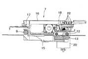
図3〜図7に示すように、記録部7は記録ヘッド15を有し、この記録ヘッド15はキャリッジ16に搭載されている。このキャリッジ16は、案内部としてのガイドレール17,18により記録紙Aの幅方向(主走査方向)に移動可能に案内されている。 As shown in FIGS. 3 to 7, the
また、ガイドレール18上の両端部近傍には、図4に示すようにプーリ19a,19bが取り付けられ、これらのプーリ19a,19bのうちのプーリ19bがヘッド移動手段としてのキャリッジモータ20と作動連結されている。そして、プーリ19a,19bには、無端ベルト21が巻き掛けられている。この無端ベルト21には、キャリッジ16が接続されている。 Also, pulleys 19a and 19b are attached in the vicinity of both ends on the
したがって、キャリッジ16は、キャリッジモータ20の回転駆動に応じてプーリ19a,19b、無端ベルト21を介してプラテン11上をガイドレール17,18に沿って上記幅方向(主走査方向)に往復移動する。 Therefore, the
搬送ローラ9およびニップローラ10のうち搬送ローラ9を駆動ローラとしているため、後述するチューブの接続側と対向する側に位置するガイドレール17は、プリンタ設置面に対して平行に形成されている。 Since the
また、拍車ローラ12および排紙ローラ13のうち排紙ローラ13を駆動ローラとしているため、後述するチューブの接続側に位置するガイドレール18は、断面L字状に形成されている。そして、上記キャリッジモータ20は、断面L字状に形成されたガイドレール18側に配置されている。 Further, since the
これらガイドレール17,18は、それぞれ金属製で、記録紙Aの幅方向全体に平面、断面L字状に形成されている。 Each of the guide rails 17 and 18 is made of metal, and is formed in a flat surface and an L-shaped cross section in the entire width direction of the recording paper A.
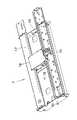
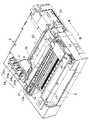
さらに、キャリッジ16の移動方向側端面であって、キャリッジ16の記録紙Aの搬送方向下流側には、図6および図7に示すように4つのチューブ接続部22が設けられている。これら4つのチューブ接続部22は、図8および図9に示すようにそれぞれインクチューブ23に一端が接続され、これらインクチューブ23の他端がインク保持部としての各インクカートリッジ24に接続されている。 Furthermore, four
各インクカートリッジ24は、ブラックのインクカートリッジ24aと、シアンのインクカートリッジ24bと、マゼンタのインクカートリッジ24cと、イエローのインクカートリッジ24dとがそれぞれ独立して交換可能に装着されている。 In each
記録ヘッド15も、図示していないがそれぞれ異なる色のインクを吐出するための4つの部分から構成されている。これらに対応して、インクチューブ23はそれぞれ異なる色のインクを流通させ、各インクタンク24a,24b,24c,24dからのインクを記録ヘッド15の対応する構成部分に供給するように構成されている。 Although not shown, the
インクチューブ23は、4本のチューブが両端部を除いて一列に並べて結合されて板状になった可撓性部材の4連チューブから形成され、その厚み方向に可撓性を有している。 The
さらに、ガイドレール18の記録紙Aの搬送方向下流側には、インクチューブ23の中央部分が当接する案内板25が立設されており、記録ヘッド15の往復移動に伴って移動するインクチューブ23を案内板25に沿わせるように案内する。そして、案内板25のインクカートリッジ24側の端部近傍には、インクチューブ23を局部的に挟み込む挟持部26が案内板25に対向して配置されている。 Further, a
したがって、インクチューブ23は、記録ヘッド15の移動方向側端面であって、記録ヘッド15の記録紙Aの搬送方向下流側に接続されている。 Therefore, the
次に、本実施形態のインクジェットプリンタ3による記録動作の概要を説明する。 Next, an outline of a recording operation by the
図2に示すように、給紙カセット4に積み重ねた記録紙Aは、その上面に当接する給紙装置6の給紙ローラ6aが回転駆動されることによって、一枚ずつ分離されて給紙される。その給送された記録紙Aは、記録部7へ案内する案内路8を経由して、搬送ローラ9とニップローラ10へと供給される。搬送ローラ9は、回転駆動されて、供給された記録紙Aをプラテン11上の所定の記録位置に導く。 As shown in FIG. 2, the recording sheets A stacked in the sheet feeding cassette 4 are separated and fed one by one by rotating the
記録紙Aが記録位置に導かれると、キャリッジモータ20が駆動されてキャリッジ16がガイドレール17,18に沿って移動され、この移動方向における記録位置を決める走査が行われる。この際に、記録ヘッド15が駆動されてインク液が吐出され、記録紙Aの所定の位置に付着されて、1走査分の画像の記録が行われる。 When the recording paper A is guided to the recording position, the
次に、記録紙Aは、1走査分の記録幅に相応する所定量だけ搬送され、その後、再びキャリッジ20がガイドレール17,18に沿って移動されながら次の1走査分の画像形成が行われる。 Next, the recording paper A is conveyed by a predetermined amount corresponding to the recording width for one scanning, and then the
このようにして、記録紙Aの所定の領域への記録が終了した後、記録紙Aは回転駆動される拍車ローラ12および排紙ローラ13によって、給紙カセット4のトレー4b上に排紙される。 In this way, after the recording of the recording paper A on the predetermined area is completed, the recording paper A is discharged onto the
以上説明した本実施形態のインクジェットプリンタ3では、上述のようにインクチューブ23は、図8および図9に示すように記録ヘッド15の移動方向側端面であって、記録ヘッド15の記録紙Aの搬送方向下流側に接続されているので、記録ヘッド15の移動時にインクチューブ23が、その記録ヘッド15の移動範囲内のプラテン11上方に、つまりガイドレール17,18間に位置することがなくなる。 In the
したがって、記録ヘッド15の移動時にインクチューブ23がガイドレール17,18間に位置することがないので、プラテン11において記録紙Aがジャムし、そのジャムした記録紙Aを取り除こうとした場合には、インクチューブ23が邪魔になることがなくなり、ジャム除去処理を容易に行うことができる。 Accordingly, since the
また、本実施形態では、記録ヘッド15に対するインクチューブ23の接続側に位置するガイドレール18を断面L字状に形成したことにより、インクジェットプリンタ3の重心に対する記録ヘッド15およびキャリッジモータ20の重量バランスが良好になり、モーメントが小さくなるため、記録ヘッド15のガタつきが防止され、記録紙Aに正確な画像を形成することができる。そして、ガイドレール18を断面L字状に形成したので、ガイドレール18の成形が容易になり、ガイドレールの低価格化を図ることができる。 In this embodiment, the
そして、本実施形態では、キャリッジモータ20を記録ヘッド15に対するインクチューブ23の接続側に配置したことにより、同様にインクジェットプリンタ3の重心に対する重量バランスが良好になり、モーメントが小さくなるため、記録ヘッド15のガタつきが防止され、記録紙Aに正確な画像を形成することができる。 In this embodiment, since the
さらに、本実施形態では、搬送ローラ9とニップローラ10を記録ヘッド15の記録紙Aの搬送方向上流側に配置し、これら搬送ローラ9とニップローラ10のうち記録ヘッド15側に位置する搬送ローラ9を駆動ローラとした場合、記録ヘッド15においてインクチューブ23の接続側と対向する側に位置するガイドレール17を、プリンタ設置面に対して平行、つまり平板状に形成したことにより、駆動ローラを逆にした場合に比べ、プリンタの高さを低くすることができるため、プリンタを薄型化することができる。 Further, in the present embodiment, the
また、本実施形態では、断面L字状に形成したガイドレール18の下方に拍車ローラ12および排紙ローラ13を配置し、これら拍車ローラ12および排紙ローラ13のうちL字状に形成したガイドレール18側に位置する拍車ローラ12と対向する排紙ローラ13を駆動ローラとしたことにより、駆動ローラを逆にした場合に比べ、プリンタの高さを低くすることができるため、プリンタを薄型化することができる。 In the present embodiment, the
なお、本発明は上記実施形態に限定されることなく、種々の変更が可能である。例えば、上記実施形態では、プリンタ機能、コピー機能、スキャナ機能、ファクシミリ機能および電話機能などを備えた多機能装置に本発明を適用した場合について説明したが、これに限定されることなく、少なくともインクジェットプリンタを備えたものであれば、如何なるものでも適用可能である。 The present invention is not limited to the above-described embodiment, and various modifications can be made. For example, in the above-described embodiment, the case where the present invention is applied to a multi-function apparatus having a printer function, a copy function, a scanner function, a facsimile function, a telephone function, and the like has been described. Any device provided with a printer is applicable.
また、上記実施形態では、被記録媒体として記録紙Aを用いた場合について説明したが、これに限らず樹脂シート、樹脂と紙との積層シートなどの各種シートを適用することができる。 Moreover, although the case where the recording paper A was used as a recording medium was demonstrated in the said embodiment, not only this but various sheets, such as a resin sheet and a laminated sheet of resin and paper, can be applied.
3 インクジェットプリンタ
4 給紙カセット
6 給紙装置
7 記録部
9 搬送ローラ
10 ニップローラ
11 プラテン
12 拍車ローラ
13 排紙ローラ
15 記録ヘッド
16 キャリッジ
17 ガイドレール
18 ガイドレール
20 キャリッジモータ
22 チューブ接続部
23 インクチューブ
24 インクカートリッジDESCRIPTION OF
Claims (5)
Translated fromJapanese該記録ヘッドとは別体に設けられたインク保持部から前記記録ヘッドにインクを供給するチューブと、
前記被記録媒体の幅方向に前記記録ヘッドの移動を案内する案内部と、
前記案内部に沿って前記記録ヘッドを往復移動させるヘッド移動手段と、
前記案内部に対して直交方向に前記被記録媒体を搬送する一対の搬送ローラと、
前記記録ヘッドにより画像が形成された被記録媒体を排出する一対の排出ローラと、
を備えたインクジェットプリンタであって、
前記チューブは、前記記録ヘッドの移動方向側端面であって、前記記録ヘッドの前記被記録媒体の搬送方向下流側に接続したことを特徴とするインクジェットプリンタ。A recording head that discharges ink to form an image on a recording medium;
A tube for supplying ink to the recording head from an ink holding portion provided separately from the recording head;
A guide for guiding the movement of the recording head in the width direction of the recording medium;
Head moving means for reciprocating the recording head along the guide portion;
A pair of transport rollers for transporting the recording medium in a direction orthogonal to the guide portion;
A pair of discharge rollers for discharging a recording medium on which an image is formed by the recording head;
An inkjet printer comprising:
The ink jet printer according to claim 1, wherein the tube is connected to an end surface on a moving direction side of the recording head and downstream of the recording head in a transport direction of the recording medium.
Priority Applications (7)
| Application Number | Priority Date | Filing Date | Title |
|---|---|---|---|
| JP2004062611AJP4151589B2 (en) | 2004-03-05 | 2004-03-05 | Inkjet printer |
| DE602005013135TDE602005013135D1 (en) | 2004-03-05 | 2005-03-04 | The image recording device |
| EP05251298AEP1574340B1 (en) | 2004-03-05 | 2005-03-04 | Image recording apparatus |
| CNB2005100531406ACN100423940C (en) | 2004-03-05 | 2005-03-04 | image recording device |
| AT05251298TATE425008T1 (en) | 2004-03-05 | 2005-03-04 | IMAGE RECORDING DEVICE |
| US11/071,315US7537322B2 (en) | 2004-03-05 | 2005-03-04 | Image recording apparatus |
| CN 200520004152CN2850917Y (en) | 2004-03-05 | 2005-03-07 | Image recording equipment |
Applications Claiming Priority (1)
| Application Number | Priority Date | Filing Date | Title |
|---|---|---|---|
| JP2004062611AJP4151589B2 (en) | 2004-03-05 | 2004-03-05 | Inkjet printer |
Publications (2)
| Publication Number | Publication Date |
|---|---|
| JP2005246863Atrue JP2005246863A (en) | 2005-09-15 |
| JP4151589B2 JP4151589B2 (en) | 2008-09-17 |
Family
ID=35027808
Family Applications (1)
| Application Number | Title | Priority Date | Filing Date |
|---|---|---|---|
| JP2004062611AExpired - Fee RelatedJP4151589B2 (en) | 2004-03-05 | 2004-03-05 | Inkjet printer |
Country Status (2)
| Country | Link |
|---|---|
| JP (1) | JP4151589B2 (en) |
| CN (1) | CN2850917Y (en) |
Families Citing this family (2)
| Publication number | Priority date | Publication date | Assignee | Title |
|---|---|---|---|---|
| JP6784059B2 (en)* | 2016-05-27 | 2020-11-11 | セイコーエプソン株式会社 | Liquid injection device |
| CN109130489B (en)* | 2017-06-15 | 2021-12-07 | 精工爱普生株式会社 | Liquid ejecting head and liquid ejecting apparatus |
- 2004
- 2004-03-05JPJP2004062611Apatent/JP4151589B2/ennot_activeExpired - Fee Related
- 2005
- 2005-03-07CNCN 200520004152patent/CN2850917Y/ennot_activeExpired - Lifetime
Also Published As
| Publication number | Publication date |
|---|---|
| JP4151589B2 (en) | 2008-09-17 |
| CN2850917Y (en) | 2006-12-27 |
Similar Documents
| Publication | Publication Date | Title |
|---|---|---|
| JP4386202B2 (en) | Paper feeding device and image recording device | |
| JP4265612B2 (en) | Image recording device | |
| JP5779873B2 (en) | Sheet cutting apparatus and image forming apparatus provided with the same | |
| JP3870104B2 (en) | Paper feeding apparatus and recording apparatus provided with the same | |
| JP2009241355A (en) | Recording device | |
| JP4221609B2 (en) | Feeding device and image recording device | |
| JP2004203513A (en) | Sheet feeding device and image reading / recording device provided with the same | |
| CN103707638B (en) | Ink-jet recording apparatus | |
| JP2021098611A (en) | Image recording device | |
| JP4151589B2 (en) | Inkjet printer | |
| JP7088267B2 (en) | Feeding device and image recording device | |
| US11186455B2 (en) | Sheet feed device and image recording apparatus | |
| JP6446947B2 (en) | Image recording device | |
| JP7714986B2 (en) | Image recording device | |
| JP6119539B2 (en) | Inkjet recording device | |
| JP6738566B2 (en) | Image recorder | |
| JP6801765B2 (en) | Feeding device and image recording device | |
| JP6347138B2 (en) | Image recording device | |
| JP6927379B2 (en) | Image recording device | |
| JP2023050334A (en) | image recorder | |
| JP2004203509A (en) | Sheet feeding device and image reading / recording device provided with the same | |
| JP2023050319A (en) | image recorder | |
| JP2021178738A (en) | Image recording device | |
| JP6503870B2 (en) | Sheet feeding apparatus and inkjet recording apparatus | |
| JP2006117339A (en) | Paper feeder |
Legal Events
| Date | Code | Title | Description |
|---|---|---|---|
| A621 | Written request for application examination | Free format text:JAPANESE INTERMEDIATE CODE: A621 Effective date:20050927 | |
| A977 | Report on retrieval | Free format text:JAPANESE INTERMEDIATE CODE: A971007 Effective date:20080214 | |
| A131 | Notification of reasons for refusal | Free format text:JAPANESE INTERMEDIATE CODE: A131 Effective date:20080226 | |
| A521 | Request for written amendment filed | Free format text:JAPANESE INTERMEDIATE CODE: A523 Effective date:20080424 | |
| TRDD | Decision of grant or rejection written | ||
| A01 | Written decision to grant a patent or to grant a registration (utility model) | Free format text:JAPANESE INTERMEDIATE CODE: A01 Effective date:20080610 | |
| A01 | Written decision to grant a patent or to grant a registration (utility model) | Free format text:JAPANESE INTERMEDIATE CODE: A01 | |
| A61 | First payment of annual fees (during grant procedure) | Free format text:JAPANESE INTERMEDIATE CODE: A61 Effective date:20080623 | |
| R150 | Certificate of patent or registration of utility model | Free format text:JAPANESE INTERMEDIATE CODE: R150 Ref document number:4151589 Country of ref document:JP Free format text:JAPANESE INTERMEDIATE CODE: R150 | |
| FPAY | Renewal fee payment (event date is renewal date of database) | Free format text:PAYMENT UNTIL: 20110711 Year of fee payment:3 | |
| FPAY | Renewal fee payment (event date is renewal date of database) | Free format text:PAYMENT UNTIL: 20120711 Year of fee payment:4 | |
| FPAY | Renewal fee payment (event date is renewal date of database) | Free format text:PAYMENT UNTIL: 20120711 Year of fee payment:4 | |
| FPAY | Renewal fee payment (event date is renewal date of database) | Free format text:PAYMENT UNTIL: 20130711 Year of fee payment:5 | |
| LAPS | Cancellation because of no payment of annual fees |