JP2005245916A - Vacuum cleaner - Google Patents
Vacuum cleanerDownload PDFInfo
- Publication number
- JP2005245916A JP2005245916AJP2004063786AJP2004063786AJP2005245916AJP 2005245916 AJP2005245916 AJP 2005245916AJP 2004063786 AJP2004063786 AJP 2004063786AJP 2004063786 AJP2004063786 AJP 2004063786AJP 2005245916 AJP2005245916 AJP 2005245916A
- Authority
- JP
- Japan
- Prior art keywords
- brush
- wall
- dust
- base
- width direction
- Prior art date
- Legal status (The legal status is an assumption and is not a legal conclusion. Google has not performed a legal analysis and makes no representation as to the accuracy of the status listed.)
- Granted
Links
- 239000000428dustSubstances0.000claimsabstractdescription72
- 239000012530fluidSubstances0.000claimsdescription46
- 230000003111delayed effectEffects0.000claimsdescription3
- 238000013459approachMethods0.000claimsdescription2
- 238000004140cleaningMethods0.000abstractdescription30
- 238000007664blowingMethods0.000abstractdescription11
- 230000000903blocking effectEffects0.000description11
- 230000002093peripheral effectEffects0.000description3
- 238000010408sweepingMethods0.000description3
- 230000008878couplingEffects0.000description2
- 238000010168coupling processMethods0.000description2
- 238000005859coupling reactionMethods0.000description2
- 238000005192partitionMethods0.000description2
- 229910000897Babbitt (metal)Inorganic materials0.000description1
- 230000004913activationEffects0.000description1
- 238000000034methodMethods0.000description1
- 238000003825pressingMethods0.000description1
- 238000007790scrapingMethods0.000description1
Images


Landscapes
- Nozzles For Electric Vacuum Cleaners (AREA)
Abstract
Description
Translated fromJapanese本発明は電気掃除機に関し、特に、壁際床面を確実に清掃することができる電気掃除機に関するものである。 The present invention relates to a vacuum cleaner, and more particularly to a vacuum cleaner capable of reliably cleaning a floor surface near a wall.
従来より、吸口ベースに収容された水平軸線まわりに回転する回転ブラシによって、床面の塵を前方に掻き上げるとともに、掻き上げられた塵を吸引空気流に混合して集塵部に吸い込み、ここで塵を捕集し、吸引空気流のみを機外に排気するように構成した電気掃除機がある(たとえば、特許文献1)。 Conventionally, the rotating brush that rotates around the horizontal axis accommodated in the suction base scrapes the dust on the floor forward, mixes the dust that has been lifted into the suction air flow, and sucks it into the dust collector. There is a vacuum cleaner configured to collect dust and exhaust only the suction air flow to the outside (for example, Patent Document 1).
ところが、特許文献1の電気掃除機では、幅方向寸法の大きい吸口ベースに回転ブラシが収容されているので、壁際床面の清掃に際しては、吸口ベースの幅方向一端が壁面に当接して、壁際床面に対する回転ブラシの接触が妨げられる。このため、回転ブラシによって壁際床面を清掃することができない。 However, in the vacuum cleaner of Patent Document 1, since the rotary brush is accommodated in the suction base having a large width direction dimension, when cleaning the floor surface near the wall, one end in the width direction of the suction base comes into contact with the wall surface. The contact of the rotating brush with the floor surface is hindered. For this reason, the floor near the wall cannot be cleaned by the rotating brush.
そこで、前記吸口ベースの前方近傍にはみ出した位置に鉛直軸線まわりに回転する回転ブラシを設け、この回転ブラシによって壁際床面を清掃することも考えられる。しかし、この方法では、壁際床面の塵の清掃には有効であるものの、壁際から離れた床面の塵は、前記鉛直軸線まわりに回転する回転ブラシによって、吸口ベースから離れた位置に掃き飛ばされてしまう。 Therefore, it is also conceivable to provide a rotating brush that rotates around the vertical axis at a position that protrudes in the vicinity of the front of the inlet base, and to clean the wall floor by this rotating brush. However, although this method is effective for cleaning the dust on the floor near the wall, the dust on the floor far from the wall is swept away from the inlet base by the rotating brush rotating around the vertical axis. Will be.
したがって、本発明の目的は、壁際から離れた床面の塵を掃き飛ばさないものでありながら、壁際床面を確実に清掃することができる電気掃除機を提供することである。 Accordingly, an object of the present invention is to provide an electric vacuum cleaner that can reliably clean the floor surface near the wall while not sweeping away dust on the floor surface far from the wall.
前記目的を達成するために、本発明に係る電気掃除機は、床面を走行可能な掃除機本体と、吸入した空気の空気流に乗せて塵を吸い上げて集塵する吸口ベースとを備え、前記吸口ベースは、前記掃除機本体と共に床面を走行し、かつ、走行方向に直交する幅方向の両端部が前記掃除機本体の幅方向の両端から突出する大きさを有し、この吸口ベースは、概ね水平な軸線のまわりに回転しながら床面に接触して当該床面の塵を前方に掻き上げる回転ブラシと、この回転ブラシを前記軸線のまわりに回転させる駆動機構と、前記回転ブラシで床面から前方に掻き上げられた塵を空気流に乗せて塵の吸引口に導く流体通路とを備えている電気掃除機において、前記吸口ベースには、該吸口ベースの少なくとも幅方向の一端から幅方向の外側に突出すると共に、前記駆動機構によって前記軸線のまわりに回転する壁際ブラシが設けられている。 In order to achieve the above object, a vacuum cleaner according to the present invention includes a vacuum cleaner main body capable of traveling on a floor surface, and a mouthpiece base that sucks up dust and collects it on an air flow of inhaled air, The mouthpiece base travels on the floor surface together with the cleaner body, and both ends in the width direction perpendicular to the running direction protrude from both ends in the width direction of the cleaner body. A rotating brush that rotates around a substantially horizontal axis and contacts the floor surface to scrape dust on the floor surface forward; a driving mechanism that rotates the rotating brush around the axis; and the rotating brush And a fluid passage that guides the dust scraped forward from the floor surface to the dust suction port by placing it on an air flow, and the suction base includes at least one end in the width direction of the suction base. Protrudes outward in the width direction from Together, the wall brush that rotates around the axis is provided by the drive mechanism.
本発明の電気掃除機によれば、掃除機本体と共に吸口ベースが床面を走行する際に、吸口ベースに設けた駆動機構によって回転ブラシが概ね水平な軸線のまわりに(ブラシ軸のまわりに)回転して床面の塵を前方に掻き上げる。床面から掻き上げられた塵は、流体通路で吸引口に吸引されている空気流に混合される。前記塵と空気流との混合流体は流体通路により案内されて塵の吸引口まで導かれて(流下して)、当該塵の吸引口に吸い込まれて吸口ベースの外部に吸い出される。
一方、壁際ブラシは、吸口ベースの少なくとも幅方向の一端から外側に突出した状態で前記軸線のまわりに回転するので、吸口ベースが壁面に当接した状態又は当接するのを避けた状態で、壁際床面の塵および壁面下端部の塵を清掃することができる。According to the electric vacuum cleaner of the present invention, when the suction base moves along with the vacuum cleaner body on the floor surface, the rotary brush is moved around the horizontal axis (around the brush axis) by the drive mechanism provided on the suction base. Rotates and sweeps the floor dust forward. The dust scooped up from the floor is mixed with the air flow sucked into the suction port in the fluid passage. The mixed fluid of the dust and the air flow is guided by the fluid passage to the dust suction port (flows down), sucked into the dust suction port, and sucked out of the suction base.
On the other hand, the brush at the wall rotates around the axis while projecting outward from at least one end of the suction base in the width direction, so that the suction base is in contact with the wall surface or in a state of avoiding contact. The dust on the floor and the dust on the lower end of the wall can be cleaned.
本発明の態様においては、前記壁際ブラシは前記軸線に沿って設けられた軸部を有し、前記軸部の外周には、該軸部の径方向の外方に向って延設された1ないし複数の刷毛部と、前記軸部の周方向において前記刷毛部に隣接する無毛部とが設けられ、前記刷毛部は、前記床面に接触する状態において、前記軸部の軸方向の基端部から外端部に近づくに従って、前記軸部の回転方向の遅れ位置から進み位置に配置されるように斜めに設けられている。
この態様によれば、壁際ブラシの刷毛部が吸口ベースの前方内側に向って塵を寄せ集めるように配置されているので、壁際以外の床面を清掃する場合でも、吸口ベースから離れた位置に塵を撒き散らしてしまうことがない。In an aspect of the present invention, the wall-side brush has a shaft portion provided along the axis, and the outer periphery of the shaft portion extends 1 outward in the radial direction of the shaft portion. Or a plurality of brush portions and a hairless portion adjacent to the brush portion in the circumferential direction of the shaft portion, the brush portion being in a state of contacting the floor surface in the axial direction of the shaft portion. As it approaches the outer end portion from the end portion, it is provided obliquely so as to be arranged from the delayed position in the rotational direction of the shaft portion to the advanced position.
According to this aspect, since the brush portion of the brush at the wall is arranged so as to collect dust toward the front inner side of the suction base, even when cleaning the floor surface other than the wall, it is at a position away from the suction base. No dust will be scattered.
この場合、たとえば、前記壁際ブラシの刷毛部は、壁際ブラシ軸の外周面から径外方向にのばして設けた列状の床面清掃刷毛部と、前記壁際ブラシ軸の軸方向外端面から軸方向外側にのばして設けた列状の壁面清掃刷毛部とを備え、前記列状の床面清掃刷毛部は、前記列状の壁面清掃刷毛部側から反対側にかけて前記壁際ブラシ軸の回転方向の進み位置から遅れ位置に変位する傾斜線上に設けられている。
これによると、壁際ブラシの回転により、壁際床面の塵は、列状の床面清掃刷毛部により、傾斜線の傾斜角に相当する内向きの傾斜角で壁際床面から内側に寄せ集められる。また、壁面下端部の塵は、列状の壁面清掃刷毛部によって掃き取られて壁際床面に落下し、前記壁際床面の塵に混入して列状の床面清掃刷毛部により壁際から離れた床面側に寄せ集められる。さらに、壁際ブラシが壁際から離れていても、壁際から離れた床面の塵を掃き飛ばすことなく、回転ブラシ側に向けて寄せ集めることができる。In this case, for example, the brush portion of the wall-side brush includes an array of floor surface cleaning brush portions that extend radially outward from the outer peripheral surface of the wall-side brush shaft, and an axial direction from the axially outer end surface of the wall-side brush shaft. A row-like wall surface cleaning brush portion provided extending outward, and the row-like floor surface cleaning brush portion advances in the rotational direction of the wall-side brush shaft from the row-like wall surface cleaning brush portion toward the opposite side. It is provided on an inclined line that is displaced from the position to the delay position.
According to this, due to the rotation of the brush at the wall, the dust on the floor near the wall is gathered inward from the floor near the wall by an inward inclination angle corresponding to the inclination angle of the inclined line by the row-like floor cleaning brush portion. . Also, the dust at the lower end of the wall surface is swept away by the line-shaped wall surface cleaning brush part and dropped onto the floor surface near the wall, mixed with the dust on the wall surface and separated from the wall side by the line-like floor surface cleaning brush part. Gathered on the floor side. Furthermore, even when the wall brush is away from the wall, it can be gathered toward the rotating brush without sweeping away dust on the floor surface away from the wall.
また、本発明においては、前記吸口ベースの幅方向の略中央部に、前記塵の吸引口と、空気を導入する導入部とを設けると共に、前記導入部から導入された空気を前記吸口ベースの両端部に導いた後、前記流体通路に導くダクトを設け、前記ダクトを流れた空気が前記両端部においてUターンするように向きを変えた後、前記流体通路の両端部から前記吸口ベースの幅方向の略中央部に設けられた前記塵の吸引口に向って流れるようにしてもよい。
このようにすれば、吸口ベースの幅方向の長さが大きくても、前記壁際ブラシで掻き上げられた塵を効率よく吸引することができる。In the present invention, the dust suction port and the introduction portion for introducing air are provided at a substantially central portion in the width direction of the suction mouth base, and the air introduced from the introduction portion is supplied to the suction mouth base. After guiding to both ends, a duct for guiding to the fluid passage is provided, and the direction of the air flowing through the duct is changed so that it makes a U-turn at the both ends, and then the width of the suction base from both ends of the fluid passage. You may make it flow toward the said dust suction opening provided in the approximate center part of the direction.
In this way, even if the length of the suction base in the width direction is large, the dust scraped up by the wall brush can be efficiently sucked.
この場合、たとえば、吸口ベースには、前記流体通路を流下している前記塵と空気流との混合流体に前記吸引口への押し込み力を負荷する送風手段と、この送風手段の吐出風を前記流体通路に導くダクトが設けられている。
これによると、送風手段の吐出風をダクトによって流体通路に導いて、当該流体通路を流下している混合流体に吸引口への押し込み力として風圧を作用させて、混合流体を確実に吸引口に吸い込ませることができる。In this case, for example, on the suction port base, a blowing unit that applies a pushing force to the suction port on the mixed fluid of the dust and the air flow flowing down the fluid passage, and the discharge air of the blowing unit A duct leading to the fluid passage is provided.
According to this, the discharge air of the air blowing means is guided to the fluid passage by the duct, and the mixed fluid flowing down the fluid passage is made to act as a pushing force to the suction port, so that the mixed fluid is reliably supplied to the suction port. Can be inhaled.
さらに、本発明においては、前記吸口ベースにおける前記壁際ブラシの前側に、当該壁際ブラシで床面から掻き上げられた塵の浮き上がりを許容すると共に、浮き上がった塵が前記流体通路に導かれるのを許容する許容凹所を前記吸口ベースの下面に形成してもよい。
このようにすれば、前記壁際ブラシで掻き上げられた塵が前記許容凹所を通って流体通路に導かれるので、壁際床面の清掃を確実に行うことができる。Further, in the present invention, the dust lifted up from the floor surface by the wall-side brush is allowed to rise to the front side of the wall-side brush in the suction base, and the lifted dust is allowed to be guided to the fluid passage. An allowable recess may be formed on the lower surface of the suction base.
In this way, the dust scraped up by the brush by the wall is guided to the fluid passage through the allowable recess, so that the floor surface at the wall can be reliably cleaned.
一方、壁際ブラシの前側には、当該壁際ブラシで床面から掻き上げられた塵の浮き上がりを許容するとともに、浮き上がった塵を前記流体通路に導く案内流路を設けてもよい。これによると、壁際ブラシで掻き上げられた壁際床面の塵を案内流路から流体通路に導いて、当該流体通路を流下している混合流体に混合させて、吸引口に向かって流下させることができる。このため、壁際床面の塵が壁際ブラシで床面から掻き上げられた直後に他部材に衝突して、再度、壁際床面に落下する不具合を回避することができる。 On the other hand, a guide channel may be provided on the front side of the wall brush so as to allow the dust lifted from the floor surface by the wall brush to be lifted and guide the lifted dust to the fluid passage. According to this, the dust on the floor surface of the wall scraped up by the brush at the wall is guided from the guide channel to the fluid passage, mixed with the mixed fluid flowing down the fluid passage, and allowed to flow down toward the suction port. Can do. For this reason, it is possible to avoid the problem that the dust on the floor near the wall collides with another member immediately after being scraped from the floor with the brush at the wall and falls again on the floor near the wall.
本発明によれば、吸口ベースの少なくとも幅方向の一端から外側に突出した状態で概ね水平な軸線のまわりに回転する壁際ブラシによって、吸口ベースが壁面に当接するのを避けた状態で、壁際床面の塵を確実に清掃することができる。 According to the present invention, the wall-side floor is provided in a state in which the suction base is prevented from coming into contact with the wall surface by the wall-side brush that rotates around a substantially horizontal axis while protruding outward from at least one end in the width direction of the suction base. Dust on the surface can be reliably cleaned.
以下、本発明に係る電気掃除機の実施形態を図面にしたがって説明する。
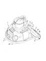
図1は電気掃除機の実施形態を示す全体斜視図である。
図1に示す電気掃除機は、掃除機本体1と、吸口ベース2とを備えている。
掃除機本体1は、床面3の走行を可能に構成されており、この掃除機本体1の後部には、当該掃除機本体1に追従して床面3の走行を可能に吸口ベース2が連結されている。また、掃除機本体1には、塵を捕集する集塵部4や、この集塵部4の内部に対して図示されていないフィルタを介して連通する空気吸引手段(図示省略)などが搭載されている。Hereinafter, embodiments of a vacuum cleaner according to the present invention will be described with reference to the drawings.
FIG. 1 is an overall perspective view showing an embodiment of a vacuum cleaner.
The vacuum cleaner shown in FIG. 1 includes a cleaner body 1 and a
The vacuum cleaner main body 1 is configured to be able to travel on the
吸口ベース2は、掃除機本体1の走行方向(矢印Y)に直交する幅方向(矢印X)の両端部2L,2Rが掃除機本体1の幅方向両端から少しはみ出す大きさのもので、図2に示すように、幅方向に長い横長のベース部20と、このベース部20を上側から着脱可能に覆うカバ−21とを備えている。図1に示すように、カバ−21によってベース部20が覆われた組立状態で、ベース部20とカバ−21の周囲はバンパ5により取り囲まれている。 The
図2に示すように、吸口ベース2のベース部20は、その上面の全てが段差付き蓋板22によって閉塞されて下側を開口してある。段差付き蓋板22は、横断面L字状の前側閉塞部22aと横断面逆向きL字状の後側閉塞部22bとを有している。両者22a,22bは、ベース部20における走行方向Yの略中央部において幅方向Xの略全長にのびて直線状に設けられた段差部22cを境界に前後に振り分けられており、前側閉塞部22aのレベル(高さ)を後側閉塞部22bのレベル(高さ)よりも高く設定してある。 As shown in FIG. 2, the
前側閉塞部22aの下側には、間隔を隔てて仕切板22dが対向して設けられ、前側閉塞部22aと仕切板22dおよび段差部22cとで取り囲まれる角形閉断面構造のダクト6が幅方向略全長にのびて設けられている。また、後側閉塞部22bの下側には、ダクト6に平行にブラシ収容室7が設けられている。このブラシ収容室7の前側で、かつ、ダクト6の下側には、図3に示す混合流体通路8がブラシ収容室7に平行して幅方向略全長にわたって設けられている(ただし、図3には、幅方向の一部のみが示されている)。混合流体通路8の幅方向両端部8L,8R(ただし、図3には、混合流体通路8の幅方向一端部のみが示されている)は、下向きの隆起部9に形成したU字状の透孔9aを介してダクト6の幅方向両端部6L,6Rに連通している。 On the lower side of the
図2に示すように、前側閉塞部22aの幅方向中央部には、ダクト6に通じる角形の開口部22eが設けられ、この開口部22eは、たとえばシロッコフアンなどの送風機からなる送風手段(導入部)10の吐出口10aによって塞がれ、送風手段10の吸込口10bは、ベース部20の前側に向けて開口している。また、後側閉塞部22bの幅方向中央部を貫通して、ブラシ収容室7に通じる貫通孔(図示省略)が設けられ、この貫通孔を塞いで塵の吸引口11が取付けられている。そして、前記混合流体通路8の幅方向中央部は吸引口11の入口に連通させ、吸引口11の出口は、図1に示すように、吸引ホース12を介して集塵部4の入口に連通させてある。 As shown in FIG. 2, a
図2,図3に示すように、ブラシ収容室7には、概ね水平な軸線C1のまわりに回転自在に支持された回転ブラシ13が収容される。この回転ブラシ13は、図1に示す床面3に接触して、当該床面3の塵を前方に掻き上げるためのもので、回転ブラシ軸13a周面から径外方向にのばした二条の床面清掃刷毛部13bを有している。これら床面清掃刷毛部13bは、大きいリードを有して螺旋状に設けられている。すなわち、床面清掃刷毛部13bは、塵を前方に掻き上げられるように回転ブラシ軸13aの軸方向の全長にわたって螺旋状に設けられている。 As shown in FIGS. 2 and 3, the brush accommodating chamber 7 accommodates a rotating
回転ブラシ13は、図2、図4および図5に示すように、回転ブラシ軸13aの両端部に取付けた一対のカップリング14A,14Bの外端部が、左右一対のブラケット15A,15Bに取付けられている軸受メタル16内部のベアリング17によって回転自在に支持されている。左右一対のブラケット15A,15Bは、後側閉塞部22bの幅方向両端部を上下に貫通してブラシ収容室7に臨ませた状態で当該後側閉塞部22bに取付けられている。 As shown in FIGS. 2, 4 and 5, the rotating
また、一方のブラケット15Aには、上方への延出片15aが設けられ、この延出片15aに回転ブラシ駆動モータ18が水平軸線を有して取付けられており、回転ブラシ駆動モータ18と、当該回転ブラシ駆動モータ18の出力軸18aに取付けられている駆動プーリ19Aと、タイミングベルト19Bおよび打ち込み連結ピン23を介して一方のカップリング14Aに同時回転可能に連結されている従動プーリ19Cとで、回転ブラシ13を前記軸線C1のまわり(矢印R)に回転させる駆動機構19が構成されている。 One
図2、図3、図4および図5に示すように、回転ブラシ13の軸方向両端部には、壁際ブラシ24L,24Rが同じ水平軸線C1まわり(矢印R)の回転を可能に取付けられて、吸口ベース2を取り囲んでいるバンパ5の幅方向両端部から外側に突出している。壁際ブラシ24は、図6および図7に示すように、壁際ブラシ軸(軸部)24Aと、刷毛部24Bとを備え、壁際ブラシ軸24Aの水平な中心線上に連結ピン圧入孔24aが設けられている。この連結ピン圧入孔24aに、図5に示す打ち込み連結ピン23における外端部を圧入することで、駆動機構19によって壁際ブラシ24を回転ブラシ13と同時に同じ水平軸線C1まわり(矢印R)に回転させるように構成してある。 As shown in FIGS. 2, 3, 4, and 5, wall-side brushes 24 </ b> L and 24 </ b> R are attached to both ends of the rotating
図6および図7に示すように、壁際ブラシ24の刷毛部24Bは、壁際ブラシ軸24Aの中心Oを通る直線C1上に位置して、当該壁際ブラシ軸24Aの軸方向外端面24bから軸方向外側にのばして設けた列状の壁面清掃刷毛部24b1と、この列状の壁面清掃刷毛部24b1の上下両端に連続して壁際ブラシ軸24Aの外周面24cから径外方向にのばして設けた上下一対の列状の床面清掃刷毛部24b2とを備えている。これら列状の床面清掃刷毛部24b2は、列状の壁面清掃刷毛部24b1側から反対側にかけて、つまり、壁際ブラシ軸24の軸方向外端面24bから反対側にかけて、壁際ブラシ軸24Aの回転方向Rの進み位置から遅れ位置に変位する傾斜線C2上に設けてある。 As shown in FIGS. 6 and 7, the
すなわち、図6および図7に示すように、走行方向Yに対して左側の壁際ブラシ24Lは、前記刷毛部24b2が、床面3に接触する状態において、前記壁際ブラシ軸24Aの基端部41から外端部42に近づくに従って、前記回転方向Rの遅れ位置から進み位置に配置されるように斜めに設けられていることで、左ネジの回転方向に沿った螺旋状に配置されている。 That is, as shown in FIGS. 6 and 7, the wall-
なお、図4および図5に示すように、前記左側の壁際ブラシ24Lに対して、右側の壁際ブラシ24Rは、右ネジの回転方向に沿った螺旋状に前記刷毛部24b2が配置されている。右側の壁際ブラシ24Rのその他の構造は、左側の壁際ブラシ24Lと同様であるため、その詳しい説明を省略する。 As shown in FIGS. 4 and 5, the brush portion 24b2 is arranged in a spiral shape along the rotational direction of the right screw in the
また、図3に示すように、混合流体通路8の幅方向両端部8L,8R(ただし、図3には、混合流体通路8の幅方向一端部のみが示されている)に形成した下向きの隆起部9の幅方向外側から前側にかけて、当該隆起部9の下向きの隆起量よりも十分に小さい下向きの隆起量を有するL字状の下向き平坦面25が形成されている。吸口ベース2にバンパ5を取付けた際に、バンパ5の内面と、L字状の平坦面25の下面および下向きの隆起部9の外面とで下向きに開口した横断面コ字状の案内流路(許容凹所)26が構成される。なお、図中27は走行輪を示す。 Further, as shown in FIG. 3, the both ends 8L and 8R in the width direction of the mixed fluid passage 8 (however, only one end portion in the width direction of the
前記構成の作動について説明する。
図1に示す掃除機本体1と吸口ベース2が床面3を矢印Y方向に走行する。この際、掃除機本体1に搭載されている空気吸引手段(図示省略)と、図2に示す吸口ベース2に設けた送風手段10および駆動機構19が起動する。前記空気吸引手段の起動によって、図2および図3に示す吸口ベース2のブラシ収容室7の前側および当該ブラシ収容室7内の空気は、図1に示す吸口ベース2の吸引口11→吸引ホース12→集塵部4の経路で、図示されていない空気吸引手段に吸引される。The operation of the above configuration will be described.
The cleaner body 1 and the
前記駆動機構19の起動によって、図2および図3に示す回転ブラシ13がブラシ軸13aまわりの矢印R方向に回転して、床面3の塵を前方に掻き上げる。床面3から掻き上げられた塵は、混合流体通路8に沿って吸引口11に吸引されている空気流に混合して吸引口11に吸い込まれ、図1に示す吸引ホース12を経て集塵部4に到達する。ここでフィルタ(図示省略)により塵が捕集され、吸引空気流のみが図示されていない空気吸引手段に吸引されて機外に排気される。 When the
回転ブラシ13と同時に左右一対の壁際ブラシ24がその壁際ブラシ軸24aまわりの矢印R方向に回転する。これら壁際ブラシ24は、吸口ベース2の幅方向両端2L,2Rから水平軸線C1を有してバンパ5の外側に突出した状態で回転するので、バンパ5が壁面(図示省略)に当接した状態又は当接するのを避けた状態で、図2の壁際床面3aの塵および壁面下端部の塵を清掃することができる。 Simultaneously with the rotating
図6および図7に示すように、壁際ブラシ24L,24Rの刷毛部24Bにおける上下一対の列状の床面清掃刷毛部24b2は、壁際ブラシ軸24L,24Rの軸方向外端面24bから反対側にかけて、壁際ブラシ軸24Aの回転方向Rの進み位置から遅れ位置に変位する傾斜線C2上に設けられているので、図2に示す壁際床面3aの塵は、図6および図7に示す列状の床面清掃刷毛部24b2により、傾斜線C2の傾斜角θに相当する内向きの傾斜角θ(図4参照)で、図2に示す壁際床面3aから床面3側に寄せ集められる(図4の矢印F参照)。また、図示されていない壁面下端部の塵は、列状の壁面清掃刷毛部24b1によって掃き取られて壁際床面3aに落下し、壁際床面3aの塵に混入して列状の床面清掃刷毛部24b2により壁際床面3aから床面3側に寄せ集められる。このように、壁際から離れた床面3側に寄せ集められた塵は、回転ブラシ13によって前方に掻き上げられたのち、混合流体通路8で吸引口11に吸引されている空気流に混合して吸引口11に吸い込まれて集塵部4で捕集される。さらに、壁際ブラシ24が壁際から離れていても、壁際から離れた床面3の塵を掃き飛ばすことなく、回転ブラシ13側に向けて寄せ集めることができる。 As shown in FIGS. 6 and 7, the pair of upper and lower rows of floor cleaning brush portions 24b2 in the
図2および図3に示す吸口ベース2には、混合流体通路8を流下している塵と空気流との混合流体に吸引口11への押し込み力を負荷する送風手段10と、この送風手段10の吐出風を混合流体通路8に導くダクト6が設けられている。つまり、送風手段10の吐出風は、図3の矢印Aで示すように、ダクト6の幅方向両端部から下向きの隆起部9に形成したU字状の透孔9aを通ってUターンするように向きを変えた後、混合流体通路8に導かれる。これにより、混合流体通路8を流下している混合流体に吸引口11への押し込み力として風圧を作用させて、混合流体を確実に吸引口11に吸い込ませることができる。すなわち、混合流体通路8における吸引口11から離れた幅方向両端部8L,8Rあるいはその近傍位置で吸引口11に向けて流下している混合流体に対して、送風手段10の吐出風圧を押し込み力として作用させて、混合流体を確実に吸引口11に吸い込ませる。 The
図3に示すように、壁際ブラシ24の前側には、当該壁際ブラシ24で床面から掻き上げられた塵の浮き上がりを許容するとともに、浮き上がった塵を混合流体通路8に導く案内流路26が設けられているので、壁際ブラシ24で掻き上げられた壁際床面3aの塵を案内流路26から混合流体通路8に導いて、当該混合流体通路8を流下している混合流体に混合させて、吸引口11に向かって流下させることができる。このため、壁際床面3aの塵が壁際ブラシ24で床面3aから掻き上げられた直後に他部材に衝突して、再度、壁際床面3aに落下する不具合を回避して、壁際床面3aの塵を確実に清掃することができる。 As shown in FIG. 3, on the front side of the wall-
前記実施形態では、回転ブラシ13の左右両端部に壁際ブラシ24を水平軸線C1まわり(矢印R)の回転を可能に取付けて、吸口ベース2を取り囲んでいるバンパ5の幅方向両端部から外側に突出させた構造で説明しているが、回転ブラシ13の左右いずれか一方の端部に壁際ブラシ24を水平軸線C1まわり(矢印R)の回転を可能に取付けて、吸口ベース2を取り囲んでいるバンパ5の幅方向一端部から外側に突出させた構造であってもよい。 In the above-described embodiment, the
また、壁際ブラシ24の刷毛部24Bは、図6および図7のように、壁面清掃刷毛部24b1によって、2つの床面清掃刷毛部24b2が連続するように設けなくてもよい。たとえば、壁面清掃刷毛部24b1の一部ないし全部を無くして、床面清掃刷毛部24b2を2つに分けて設けるようにしてもよい。
また、床面清掃刷毛部24b2は、1つでもよいし、3つ以上設けてもよい。
さらに、図6や図7では、刷毛部24Bを模式的に板状に図示したが、刷毛部24Bは、厚みのある束状に設けるようにしてもよい。Further, as shown in FIGS. 6 and 7, the
Moreover, the floor surface cleaning brush part 24b2 may be one, and may provide three or more.
Further, in FIG. 6 and FIG. 7, the
1:掃除機本体
2:吸口ベース
3:床面
6:ダクト
8:混合流体通路
10:送風手段(導入部)
11:塵の吸引口
13:回転ブラシ
24:壁際ブラシ
24A:壁際ブラシ軸(軸部)
24b2:列状の床面清掃刷毛部(刷毛部の一例)
26:案内流路(許容凹所)
29:無毛部
41:基端部
42:外端部
C1:水平な軸線
C2:傾斜線
矢印R:ブラシの回転方向
矢印X:電気掃除機の幅方向
矢印Y:電気掃除機の走行方向1: Vacuum cleaner body 2: Suction base 3: Floor surface 6: Duct 8: Mixed fluid passage 10: Blowing means (introduction part)
11: Dust suction port 13: Rotating brush 24: Brush at the
24b2: Lined floor surface cleaning brush part (an example of a brush part)
26: Guide channel (allowable recess)
29: Hairless portion 41: Base end portion 42: Outer end portion C1: Horizontal axis C2: Inclined line Arrow R: Direction of rotation of brush Arrow X: Width direction of vacuum cleaner Arrow Y: Travel direction of vacuum cleaner
Claims (4)
Translated fromJapanese前記吸口ベースは、前記掃除機本体と共に床面を走行し、かつ、走行方向に直交する幅方向の両端部が前記掃除機本体の幅方向の両端から突出する大きさを有し、この吸口ベースは、概ね水平な軸線のまわりに回転しながら床面に接触して当該床面の塵を前方に掻き上げる回転ブラシと、この回転ブラシを前記軸線のまわりに回転させる駆動機構と、前記回転ブラシで床面から前方に掻き上げられた塵を空気流に乗せて塵の吸引口に導く流体通路とを備えている電気掃除機において、
前記吸口ベースには、該吸口ベースの少なくとも幅方向の一端から幅方向の外側に突出すると共に、前記駆動機構によって前記軸線のまわりに回転する壁際ブラシが設けられていることを特徴とする電気掃除機。A vacuum cleaner body that can run on the floor, and a suction base that sucks up dust and collects it in the airflow of the inhaled air.
The mouthpiece base travels on the floor surface together with the cleaner body, and both ends in the width direction perpendicular to the running direction protrude from both ends in the width direction of the cleaner body. A rotating brush that rotates around a substantially horizontal axis and contacts the floor surface to scrape dust on the floor surface forward; a driving mechanism that rotates the rotating brush around the axis; and the rotating brush In a vacuum cleaner comprising a fluid passage that guides the dust scraped forward from the floor surface to the dust suction port by putting it on an air flow,
The suction base is provided with a wall brush that protrudes outward in the width direction from at least one end in the width direction of the suction base and rotates around the axis by the drive mechanism. Machine.
前記軸部の外周には、該軸部の径方向の外方に向って延設された1ないし複数の刷毛部と、前記軸部の周方向において前記刷毛部に隣接する無毛部とが設けられ、
前記刷毛部は、前記床面に接触する状態において、前記軸部の軸方向の基端部から外端部に近づくに従って、前記軸部の回転方向の遅れ位置から進み位置に配置されるように斜めに設けられていることを特徴とする電気掃除機。The wall-side brush according to claim 1, wherein the wall-side brush has a shaft portion provided along the axis.
On the outer periphery of the shaft portion, there are one or a plurality of brush portions extending outward in the radial direction of the shaft portion, and a hairless portion adjacent to the brush portion in the circumferential direction of the shaft portion. Provided,
The brush portion is arranged at the advanced position from the delayed position in the rotation direction of the shaft portion as it approaches the outer end portion from the axial base end portion of the shaft portion in a state of contacting the floor surface. The vacuum cleaner characterized by being provided diagonally.
前記導入部から導入された空気を前記吸口ベースの両端部に導いた後、前記流体通路に導くダクトが設けられ、
前記ダクトを流れた空気が前記両端部においてUターンするように向きを変えた後、前記流体通路の両端部から前記吸口ベースの幅方向の略中央部に設けられた前記塵の吸引口に向って流れるようにしたことを特徴とする電気掃除機。In Claim 1 or 2, the suction port for the dust and an introduction portion for introducing air are provided at a substantially central portion in the width direction of the suction port base,
A duct is provided for guiding the air introduced from the introduction part to both ends of the suction base and then leading to the fluid passage.
After changing the direction so that the air flowing through the duct makes a U-turn at both ends, the air flows from both ends of the fluid passage toward the dust suction port provided at the substantially central portion in the width direction of the suction base. A vacuum cleaner characterized by being made to flow.
Priority Applications (1)
| Application Number | Priority Date | Filing Date | Title |
|---|---|---|---|
| JP2004063786AJP4309785B2 (en) | 2004-03-08 | 2004-03-08 | Electric vacuum cleaner |
Applications Claiming Priority (1)
| Application Number | Priority Date | Filing Date | Title |
|---|---|---|---|
| JP2004063786AJP4309785B2 (en) | 2004-03-08 | 2004-03-08 | Electric vacuum cleaner |
Publications (2)
| Publication Number | Publication Date |
|---|---|
| JP2005245916Atrue JP2005245916A (en) | 2005-09-15 |
| JP4309785B2 JP4309785B2 (en) | 2009-08-05 |
Family
ID=35026956
Family Applications (1)
| Application Number | Title | Priority Date | Filing Date |
|---|---|---|---|
| JP2004063786AExpired - LifetimeJP4309785B2 (en) | 2004-03-08 | 2004-03-08 | Electric vacuum cleaner |
Country Status (1)
| Country | Link |
|---|---|
| JP (1) | JP4309785B2 (en) |
Cited By (30)
| Publication number | Priority date | Publication date | Assignee | Title |
|---|---|---|---|---|
| GB2432301A (en)* | 2005-11-21 | 2007-05-23 | Sharp Kk | Vacuum cleaner |
| US8239992B2 (en) | 2007-05-09 | 2012-08-14 | Irobot Corporation | Compact autonomous coverage robot |
| US8253368B2 (en) | 2004-01-28 | 2012-08-28 | Irobot Corporation | Debris sensor for cleaning apparatus |
| US8368339B2 (en) | 2001-01-24 | 2013-02-05 | Irobot Corporation | Robot confinement |
| US8374721B2 (en) | 2005-12-02 | 2013-02-12 | Irobot Corporation | Robot system |
| US8380350B2 (en) | 2005-12-02 | 2013-02-19 | Irobot Corporation | Autonomous coverage robot navigation system |
| US8386081B2 (en) | 2002-09-13 | 2013-02-26 | Irobot Corporation | Navigational control system for a robotic device |
| US8382906B2 (en) | 2005-02-18 | 2013-02-26 | Irobot Corporation | Autonomous surface cleaning robot for wet cleaning |
| US8387193B2 (en) | 2005-02-18 | 2013-03-05 | Irobot Corporation | Autonomous surface cleaning robot for wet and dry cleaning |
| US8390251B2 (en) | 2004-01-21 | 2013-03-05 | Irobot Corporation | Autonomous robot auto-docking and energy management systems and methods |
| US8396592B2 (en) | 2001-06-12 | 2013-03-12 | Irobot Corporation | Method and system for multi-mode coverage for an autonomous robot |
| US8412377B2 (en) | 2000-01-24 | 2013-04-02 | Irobot Corporation | Obstacle following sensor scheme for a mobile robot |
| US8417383B2 (en) | 2006-05-31 | 2013-04-09 | Irobot Corporation | Detecting robot stasis |
| US8418303B2 (en) | 2006-05-19 | 2013-04-16 | Irobot Corporation | Cleaning robot roller processing |
| US8428778B2 (en) | 2002-09-13 | 2013-04-23 | Irobot Corporation | Navigational control system for a robotic device |
| US8463438B2 (en) | 2001-06-12 | 2013-06-11 | Irobot Corporation | Method and system for multi-mode coverage for an autonomous robot |
| US8474090B2 (en) | 2002-01-03 | 2013-07-02 | Irobot Corporation | Autonomous floor-cleaning robot |
| US8515578B2 (en) | 2002-09-13 | 2013-08-20 | Irobot Corporation | Navigational control system for a robotic device |
| US8584307B2 (en) | 2005-12-02 | 2013-11-19 | Irobot Corporation | Modular robot |
| US8600553B2 (en) | 2005-12-02 | 2013-12-03 | Irobot Corporation | Coverage robot mobility |
| US8739355B2 (en) | 2005-02-18 | 2014-06-03 | Irobot Corporation | Autonomous surface cleaning robot for dry cleaning |
| US8752240B2 (en) | 2010-12-29 | 2014-06-17 | Bissell Homecare, Inc. | Suction nozzle with obstacle sensor |
| US8780342B2 (en) | 2004-03-29 | 2014-07-15 | Irobot Corporation | Methods and apparatus for position estimation using reflected light sources |
| US8788092B2 (en) | 2000-01-24 | 2014-07-22 | Irobot Corporation | Obstacle following sensor scheme for a mobile robot |
| US8800107B2 (en) | 2010-02-16 | 2014-08-12 | Irobot Corporation | Vacuum brush |
| US8874264B1 (en) | 2004-07-07 | 2014-10-28 | Irobot Corporation | Celestial navigation system for an autonomous robot |
| US8930023B2 (en) | 2009-11-06 | 2015-01-06 | Irobot Corporation | Localization by learning of wave-signal distributions |
| US8972052B2 (en) | 2004-07-07 | 2015-03-03 | Irobot Corporation | Celestial navigation system for an autonomous vehicle |
| US9008835B2 (en) | 2004-06-24 | 2015-04-14 | Irobot Corporation | Remote control scheduler and method for autonomous robotic device |
| WO2023137884A1 (en)* | 2022-01-18 | 2023-07-27 | 深圳市杉川机器人有限公司 | Roller brush of floor scrubber and floor brush of floor scrubber |
- 2004
- 2004-03-08JPJP2004063786Apatent/JP4309785B2/ennot_activeExpired - Lifetime
Cited By (97)
| Publication number | Priority date | Publication date | Assignee | Title |
|---|---|---|---|---|
| US9446521B2 (en) | 2000-01-24 | 2016-09-20 | Irobot Corporation | Obstacle following sensor scheme for a mobile robot |
| US8788092B2 (en) | 2000-01-24 | 2014-07-22 | Irobot Corporation | Obstacle following sensor scheme for a mobile robot |
| US8478442B2 (en) | 2000-01-24 | 2013-07-02 | Irobot Corporation | Obstacle following sensor scheme for a mobile robot |
| US8565920B2 (en) | 2000-01-24 | 2013-10-22 | Irobot Corporation | Obstacle following sensor scheme for a mobile robot |
| US8412377B2 (en) | 2000-01-24 | 2013-04-02 | Irobot Corporation | Obstacle following sensor scheme for a mobile robot |
| US8761935B2 (en) | 2000-01-24 | 2014-06-24 | Irobot Corporation | Obstacle following sensor scheme for a mobile robot |
| US9144361B2 (en) | 2000-04-04 | 2015-09-29 | Irobot Corporation | Debris sensor for cleaning apparatus |
| US8368339B2 (en) | 2001-01-24 | 2013-02-05 | Irobot Corporation | Robot confinement |
| US9582005B2 (en) | 2001-01-24 | 2017-02-28 | Irobot Corporation | Robot confinement |
| US8686679B2 (en) | 2001-01-24 | 2014-04-01 | Irobot Corporation | Robot confinement |
| US8659256B2 (en) | 2001-01-24 | 2014-02-25 | Irobot Corporation | Robot confinement |
| US8659255B2 (en) | 2001-01-24 | 2014-02-25 | Irobot Corporation | Robot confinement |
| US9038233B2 (en) | 2001-01-24 | 2015-05-26 | Irobot Corporation | Autonomous floor-cleaning robot |
| US9622635B2 (en) | 2001-01-24 | 2017-04-18 | Irobot Corporation | Autonomous floor-cleaning robot |
| US9104204B2 (en) | 2001-06-12 | 2015-08-11 | Irobot Corporation | Method and system for multi-mode coverage for an autonomous robot |
| US8838274B2 (en) | 2001-06-12 | 2014-09-16 | Irobot Corporation | Method and system for multi-mode coverage for an autonomous robot |
| US8396592B2 (en) | 2001-06-12 | 2013-03-12 | Irobot Corporation | Method and system for multi-mode coverage for an autonomous robot |
| US8463438B2 (en) | 2001-06-12 | 2013-06-11 | Irobot Corporation | Method and system for multi-mode coverage for an autonomous robot |
| US8763199B2 (en) | 2002-01-03 | 2014-07-01 | Irobot Corporation | Autonomous floor-cleaning robot |
| US8656550B2 (en) | 2002-01-03 | 2014-02-25 | Irobot Corporation | Autonomous floor-cleaning robot |
| US8516651B2 (en) | 2002-01-03 | 2013-08-27 | Irobot Corporation | Autonomous floor-cleaning robot |
| US8671507B2 (en) | 2002-01-03 | 2014-03-18 | Irobot Corporation | Autonomous floor-cleaning robot |
| US8474090B2 (en) | 2002-01-03 | 2013-07-02 | Irobot Corporation | Autonomous floor-cleaning robot |
| US9128486B2 (en) | 2002-01-24 | 2015-09-08 | Irobot Corporation | Navigational control system for a robotic device |
| US8515578B2 (en) | 2002-09-13 | 2013-08-20 | Irobot Corporation | Navigational control system for a robotic device |
| US8428778B2 (en) | 2002-09-13 | 2013-04-23 | Irobot Corporation | Navigational control system for a robotic device |
| US8781626B2 (en) | 2002-09-13 | 2014-07-15 | Irobot Corporation | Navigational control system for a robotic device |
| US8386081B2 (en) | 2002-09-13 | 2013-02-26 | Irobot Corporation | Navigational control system for a robotic device |
| US8793020B2 (en) | 2002-09-13 | 2014-07-29 | Irobot Corporation | Navigational control system for a robotic device |
| US9949608B2 (en) | 2002-09-13 | 2018-04-24 | Irobot Corporation | Navigational control system for a robotic device |
| US9215957B2 (en) | 2004-01-21 | 2015-12-22 | Irobot Corporation | Autonomous robot auto-docking and energy management systems and methods |
| US8854001B2 (en) | 2004-01-21 | 2014-10-07 | Irobot Corporation | Autonomous robot auto-docking and energy management systems and methods |
| US8461803B2 (en) | 2004-01-21 | 2013-06-11 | Irobot Corporation | Autonomous robot auto-docking and energy management systems and methods |
| US8390251B2 (en) | 2004-01-21 | 2013-03-05 | Irobot Corporation | Autonomous robot auto-docking and energy management systems and methods |
| US8749196B2 (en) | 2004-01-21 | 2014-06-10 | Irobot Corporation | Autonomous robot auto-docking and energy management systems and methods |
| US8598829B2 (en) | 2004-01-28 | 2013-12-03 | Irobot Corporation | Debris sensor for cleaning apparatus |
| US8456125B2 (en) | 2004-01-28 | 2013-06-04 | Irobot Corporation | Debris sensor for cleaning apparatus |
| US8378613B2 (en) | 2004-01-28 | 2013-02-19 | Irobot Corporation | Debris sensor for cleaning apparatus |
| US8253368B2 (en) | 2004-01-28 | 2012-08-28 | Irobot Corporation | Debris sensor for cleaning apparatus |
| US8780342B2 (en) | 2004-03-29 | 2014-07-15 | Irobot Corporation | Methods and apparatus for position estimation using reflected light sources |
| US9360300B2 (en) | 2004-03-29 | 2016-06-07 | Irobot Corporation | Methods and apparatus for position estimation using reflected light sources |
| US9486924B2 (en) | 2004-06-24 | 2016-11-08 | Irobot Corporation | Remote control scheduler and method for autonomous robotic device |
| US9008835B2 (en) | 2004-06-24 | 2015-04-14 | Irobot Corporation | Remote control scheduler and method for autonomous robotic device |
| US9223749B2 (en) | 2004-07-07 | 2015-12-29 | Irobot Corporation | Celestial navigation system for an autonomous vehicle |
| US9229454B1 (en) | 2004-07-07 | 2016-01-05 | Irobot Corporation | Autonomous mobile robot system |
| US8972052B2 (en) | 2004-07-07 | 2015-03-03 | Irobot Corporation | Celestial navigation system for an autonomous vehicle |
| US8874264B1 (en) | 2004-07-07 | 2014-10-28 | Irobot Corporation | Celestial navigation system for an autonomous robot |
| US8985127B2 (en) | 2005-02-18 | 2015-03-24 | Irobot Corporation | Autonomous surface cleaning robot for wet cleaning |
| US8382906B2 (en) | 2005-02-18 | 2013-02-26 | Irobot Corporation | Autonomous surface cleaning robot for wet cleaning |
| US8782848B2 (en) | 2005-02-18 | 2014-07-22 | Irobot Corporation | Autonomous surface cleaning robot for dry cleaning |
| US8739355B2 (en) | 2005-02-18 | 2014-06-03 | Irobot Corporation | Autonomous surface cleaning robot for dry cleaning |
| US8392021B2 (en) | 2005-02-18 | 2013-03-05 | Irobot Corporation | Autonomous surface cleaning robot for wet cleaning |
| US8387193B2 (en) | 2005-02-18 | 2013-03-05 | Irobot Corporation | Autonomous surface cleaning robot for wet and dry cleaning |
| US8670866B2 (en) | 2005-02-18 | 2014-03-11 | Irobot Corporation | Autonomous surface cleaning robot for wet and dry cleaning |
| US9445702B2 (en) | 2005-02-18 | 2016-09-20 | Irobot Corporation | Autonomous surface cleaning robot for wet and dry cleaning |
| US8774966B2 (en) | 2005-02-18 | 2014-07-08 | Irobot Corporation | Autonomous surface cleaning robot for wet and dry cleaning |
| US8855813B2 (en) | 2005-02-18 | 2014-10-07 | Irobot Corporation | Autonomous surface cleaning robot for wet and dry cleaning |
| GB2432301A (en)* | 2005-11-21 | 2007-05-23 | Sharp Kk | Vacuum cleaner |
| US9599990B2 (en) | 2005-12-02 | 2017-03-21 | Irobot Corporation | Robot system |
| US10524629B2 (en) | 2005-12-02 | 2020-01-07 | Irobot Corporation | Modular Robot |
| US8950038B2 (en) | 2005-12-02 | 2015-02-10 | Irobot Corporation | Modular robot |
| US8954192B2 (en) | 2005-12-02 | 2015-02-10 | Irobot Corporation | Navigating autonomous coverage robots |
| US8761931B2 (en) | 2005-12-02 | 2014-06-24 | Irobot Corporation | Robot system |
| US8978196B2 (en) | 2005-12-02 | 2015-03-17 | Irobot Corporation | Coverage robot mobility |
| US8661605B2 (en) | 2005-12-02 | 2014-03-04 | Irobot Corporation | Coverage robot mobility |
| US8606401B2 (en) | 2005-12-02 | 2013-12-10 | Irobot Corporation | Autonomous coverage robot navigation system |
| US8380350B2 (en) | 2005-12-02 | 2013-02-19 | Irobot Corporation | Autonomous coverage robot navigation system |
| US9392920B2 (en) | 2005-12-02 | 2016-07-19 | Irobot Corporation | Robot system |
| US8600553B2 (en) | 2005-12-02 | 2013-12-03 | Irobot Corporation | Coverage robot mobility |
| US8374721B2 (en) | 2005-12-02 | 2013-02-12 | Irobot Corporation | Robot system |
| US9144360B2 (en) | 2005-12-02 | 2015-09-29 | Irobot Corporation | Autonomous coverage robot navigation system |
| US9149170B2 (en) | 2005-12-02 | 2015-10-06 | Irobot Corporation | Navigating autonomous coverage robots |
| US8584307B2 (en) | 2005-12-02 | 2013-11-19 | Irobot Corporation | Modular robot |
| US8584305B2 (en) | 2005-12-02 | 2013-11-19 | Irobot Corporation | Modular robot |
| US8418303B2 (en) | 2006-05-19 | 2013-04-16 | Irobot Corporation | Cleaning robot roller processing |
| US9492048B2 (en) | 2006-05-19 | 2016-11-15 | Irobot Corporation | Removing debris from cleaning robots |
| US10244915B2 (en) | 2006-05-19 | 2019-04-02 | Irobot Corporation | Coverage robots and associated cleaning bins |
| US9955841B2 (en) | 2006-05-19 | 2018-05-01 | Irobot Corporation | Removing debris from cleaning robots |
| US8572799B2 (en) | 2006-05-19 | 2013-11-05 | Irobot Corporation | Removing debris from cleaning robots |
| US8528157B2 (en) | 2006-05-19 | 2013-09-10 | Irobot Corporation | Coverage robots and associated cleaning bins |
| US8417383B2 (en) | 2006-05-31 | 2013-04-09 | Irobot Corporation | Detecting robot stasis |
| US9317038B2 (en) | 2006-05-31 | 2016-04-19 | Irobot Corporation | Detecting robot stasis |
| US10299652B2 (en) | 2007-05-09 | 2019-05-28 | Irobot Corporation | Autonomous coverage robot |
| US8438695B2 (en) | 2007-05-09 | 2013-05-14 | Irobot Corporation | Autonomous coverage robot sensing |
| US9480381B2 (en) | 2007-05-09 | 2016-11-01 | Irobot Corporation | Compact autonomous coverage robot |
| US11498438B2 (en) | 2007-05-09 | 2022-11-15 | Irobot Corporation | Autonomous coverage robot |
| US8239992B2 (en) | 2007-05-09 | 2012-08-14 | Irobot Corporation | Compact autonomous coverage robot |
| US11072250B2 (en) | 2007-05-09 | 2021-07-27 | Irobot Corporation | Autonomous coverage robot sensing |
| US10070764B2 (en) | 2007-05-09 | 2018-09-11 | Irobot Corporation | Compact autonomous coverage robot |
| US8839477B2 (en) | 2007-05-09 | 2014-09-23 | Irobot Corporation | Compact autonomous coverage robot |
| US8726454B2 (en) | 2007-05-09 | 2014-05-20 | Irobot Corporation | Autonomous coverage robot |
| US8930023B2 (en) | 2009-11-06 | 2015-01-06 | Irobot Corporation | Localization by learning of wave-signal distributions |
| US10314449B2 (en) | 2010-02-16 | 2019-06-11 | Irobot Corporation | Vacuum brush |
| US11058271B2 (en) | 2010-02-16 | 2021-07-13 | Irobot Corporation | Vacuum brush |
| US8800107B2 (en) | 2010-02-16 | 2014-08-12 | Irobot Corporation | Vacuum brush |
| US8752240B2 (en) | 2010-12-29 | 2014-06-17 | Bissell Homecare, Inc. | Suction nozzle with obstacle sensor |
| WO2023137884A1 (en)* | 2022-01-18 | 2023-07-27 | 深圳市杉川机器人有限公司 | Roller brush of floor scrubber and floor brush of floor scrubber |
Also Published As
| Publication number | Publication date |
|---|---|
| JP4309785B2 (en) | 2009-08-05 |
Similar Documents
| Publication | Publication Date | Title |
|---|---|---|
| JP4309785B2 (en) | Electric vacuum cleaner | |
| CN101273860B (en) | Robot cleaner with improved dust collector | |
| CN108888177B (en) | Rolling brush assembly and cleaning device with same | |
| JP5914589B2 (en) | Vacuum cleaner head for vacuum cleaner | |
| JP3858217B2 (en) | Vacuum cleaner | |
| JP2006312066A (en) | Electric vacuum cleaner | |
| JP2006296697A (en) | Cleaning robot | |
| KR20090034493A (en) | robotic vacuum | |
| JP4269219B2 (en) | Air conditioner | |
| JP3813811B2 (en) | Suction port and vacuum cleaner | |
| KR100504890B1 (en) | Suction apparatus of upright cleaner | |
| KR101292537B1 (en) | Robot cleaner | |
| JP2001149281A (en) | Suction port body and vacuum cleaner | |
| CN218606442U (en) | Brush head module for cleaning machine and cleaning machine | |
| KR100539745B1 (en) | Flow generator of upright cleaner | |
| JP3446932B2 (en) | Vacuum cleaner suction body | |
| KR200165422Y1 (en) | Brushing device for the blackboard eraser | |
| KR102206564B1 (en) | Cleaner | |
| KR100492593B1 (en) | Upright cleaner | |
| JP3730507B2 (en) | Suction port and vacuum cleaner | |
| KR200306319Y1 (en) | Vacuum cleaning appointment suction head the brush is had built-in | |
| KR20080051507A (en) | Drum Brush Unit of Vacuum Cleaner | |
| JP3525066B2 (en) | Suction port body and vacuum cleaner | |
| JP3303861B2 (en) | Vacuum cleaner and suction device for vacuum cleaner | |
| JPH02114Y2 (en) |
Legal Events
| Date | Code | Title | Description |
|---|---|---|---|
| A621 | Written request for application examination | Free format text:JAPANESE INTERMEDIATE CODE: A621 Effective date:20070209 | |
| A977 | Report on retrieval | Free format text:JAPANESE INTERMEDIATE CODE: A971007 Effective date:20090129 | |
| A131 | Notification of reasons for refusal | Free format text:JAPANESE INTERMEDIATE CODE: A131 Effective date:20090210 | |
| A521 | Request for written amendment filed | Free format text:JAPANESE INTERMEDIATE CODE: A523 Effective date:20090324 | |
| TRDD | Decision of grant or rejection written | ||
| A01 | Written decision to grant a patent or to grant a registration (utility model) | Free format text:JAPANESE INTERMEDIATE CODE: A01 Effective date:20090421 | |
| A01 | Written decision to grant a patent or to grant a registration (utility model) | Free format text:JAPANESE INTERMEDIATE CODE: A01 | |
| A61 | First payment of annual fees (during grant procedure) | Free format text:JAPANESE INTERMEDIATE CODE: A61 Effective date:20090508 | |
| R150 | Certificate of patent or registration of utility model | Ref document number:4309785 Country of ref document:JP Free format text:JAPANESE INTERMEDIATE CODE: R150 Free format text:JAPANESE INTERMEDIATE CODE: R150 | |
| FPAY | Renewal fee payment (event date is renewal date of database) | Free format text:PAYMENT UNTIL: 20120515 Year of fee payment:3 | |
| FPAY | Renewal fee payment (event date is renewal date of database) | Free format text:PAYMENT UNTIL: 20120515 Year of fee payment:3 | |
| FPAY | Renewal fee payment (event date is renewal date of database) | Free format text:PAYMENT UNTIL: 20120515 Year of fee payment:3 | |
| S531 | Written request for registration of change of domicile | Free format text:JAPANESE INTERMEDIATE CODE: R313531 | |
| FPAY | Renewal fee payment (event date is renewal date of database) | Free format text:PAYMENT UNTIL: 20120515 Year of fee payment:3 | |
| R360 | Written notification for declining of transfer of rights | Free format text:JAPANESE INTERMEDIATE CODE: R360 | |
| FPAY | Renewal fee payment (event date is renewal date of database) | Free format text:PAYMENT UNTIL: 20120515 Year of fee payment:3 | |
| FPAY | Renewal fee payment (event date is renewal date of database) | Free format text:PAYMENT UNTIL: 20120515 Year of fee payment:3 | |
| R370 | Written measure of declining of transfer procedure | Free format text:JAPANESE INTERMEDIATE CODE: R370 | |
| FPAY | Renewal fee payment (event date is renewal date of database) | Free format text:PAYMENT UNTIL: 20120515 Year of fee payment:3 | |
| S531 | Written request for registration of change of domicile | Free format text:JAPANESE INTERMEDIATE CODE: R313531 | |
| FPAY | Renewal fee payment (event date is renewal date of database) | Free format text:PAYMENT UNTIL: 20120515 Year of fee payment:3 | |
| R350 | Written notification of registration of transfer | Free format text:JAPANESE INTERMEDIATE CODE: R350 | |
| FPAY | Renewal fee payment (event date is renewal date of database) | Free format text:PAYMENT UNTIL: 20120515 Year of fee payment:3 | |
| FPAY | Renewal fee payment (event date is renewal date of database) | Free format text:PAYMENT UNTIL: 20130515 Year of fee payment:4 | |
| FPAY | Renewal fee payment (event date is renewal date of database) | Free format text:PAYMENT UNTIL: 20130515 Year of fee payment:4 | |
| S531 | Written request for registration of change of domicile | Free format text:JAPANESE INTERMEDIATE CODE: R313531 | |
| R350 | Written notification of registration of transfer | Free format text:JAPANESE INTERMEDIATE CODE: R350 | |
| EXPY | Cancellation because of completion of term |