JP2005243326A - Hybrid power supply system - Google Patents
Hybrid power supply systemDownload PDFInfo
- Publication number
- JP2005243326A JP2005243326AJP2004049021AJP2004049021AJP2005243326AJP 2005243326 AJP2005243326 AJP 2005243326AJP 2004049021 AJP2004049021 AJP 2004049021AJP 2004049021 AJP2004049021 AJP 2004049021AJP 2005243326 AJP2005243326 AJP 2005243326A
- Authority
- JP
- Japan
- Prior art keywords
- battery
- panel
- redox flow
- reaction cell
- power supply
- Prior art date
- Legal status (The legal status is an assumption and is not a legal conclusion. Google has not performed a legal analysis and makes no representation as to the accuracy of the status listed.)
- Withdrawn
Links
- 238000006243chemical reactionMethods0.000claimsabstractdescription47
- 239000003792electrolyteSubstances0.000claimsdescription25
- 238000001816coolingMethods0.000claimsdescription7
- 239000008151electrolyte solutionSubstances0.000abstractdescription14
- 239000000243solutionSubstances0.000abstractdescription9
- 239000007788liquidSubstances0.000description20
- 229910052720vanadiumInorganic materials0.000description12
- LEONUFNNVUYDNQ-UHFFFAOYSA-Nvanadium atomChemical compound[V]LEONUFNNVUYDNQ-UHFFFAOYSA-N0.000description12
- 238000010586diagramMethods0.000description7
- QAOWNCQODCNURD-UHFFFAOYSA-NSulfuric acidChemical compoundOS(O)(=O)=OQAOWNCQODCNURD-UHFFFAOYSA-N0.000description4
- 238000009434installationMethods0.000description3
- 238000012423maintenanceMethods0.000description2
- IJGRMHOSHXDMSA-UHFFFAOYSA-NAtomic nitrogenChemical compoundN#NIJGRMHOSHXDMSA-UHFFFAOYSA-N0.000description1
- 229910001873dinitrogenInorganic materials0.000description1
- 230000005484gravityEffects0.000description1
- 239000003014ion exchange membraneSubstances0.000description1
- 238000010248power generationMethods0.000description1
- 238000005086pumpingMethods0.000description1
- 238000010926purgeMethods0.000description1
- 238000000926separation methodMethods0.000description1
- 238000000638solvent extractionMethods0.000description1
- 238000009423ventilationMethods0.000description1
- 238000004078waterproofingMethods0.000description1
Images


Classifications
- Y—GENERAL TAGGING OF NEW TECHNOLOGICAL DEVELOPMENTS; GENERAL TAGGING OF CROSS-SECTIONAL TECHNOLOGIES SPANNING OVER SEVERAL SECTIONS OF THE IPC; TECHNICAL SUBJECTS COVERED BY FORMER USPC CROSS-REFERENCE ART COLLECTIONS [XRACs] AND DIGESTS
- Y02—TECHNOLOGIES OR APPLICATIONS FOR MITIGATION OR ADAPTATION AGAINST CLIMATE CHANGE
- Y02B—CLIMATE CHANGE MITIGATION TECHNOLOGIES RELATED TO BUILDINGS, e.g. HOUSING, HOUSE APPLIANCES OR RELATED END-USER APPLICATIONS
- Y02B10/00—Integration of renewable energy sources in buildings
- Y02B10/10—Photovoltaic [PV]
- Y—GENERAL TAGGING OF NEW TECHNOLOGICAL DEVELOPMENTS; GENERAL TAGGING OF CROSS-SECTIONAL TECHNOLOGIES SPANNING OVER SEVERAL SECTIONS OF THE IPC; TECHNICAL SUBJECTS COVERED BY FORMER USPC CROSS-REFERENCE ART COLLECTIONS [XRACs] AND DIGESTS
- Y02—TECHNOLOGIES OR APPLICATIONS FOR MITIGATION OR ADAPTATION AGAINST CLIMATE CHANGE
- Y02E—REDUCTION OF GREENHOUSE GAS [GHG] EMISSIONS, RELATED TO ENERGY GENERATION, TRANSMISSION OR DISTRIBUTION
- Y02E10/00—Energy generation through renewable energy sources
- Y02E10/50—Photovoltaic [PV] energy
- Y—GENERAL TAGGING OF NEW TECHNOLOGICAL DEVELOPMENTS; GENERAL TAGGING OF CROSS-SECTIONAL TECHNOLOGIES SPANNING OVER SEVERAL SECTIONS OF THE IPC; TECHNICAL SUBJECTS COVERED BY FORMER USPC CROSS-REFERENCE ART COLLECTIONS [XRACs] AND DIGESTS
- Y02—TECHNOLOGIES OR APPLICATIONS FOR MITIGATION OR ADAPTATION AGAINST CLIMATE CHANGE
- Y02E—REDUCTION OF GREENHOUSE GAS [GHG] EMISSIONS, RELATED TO ENERGY GENERATION, TRANSMISSION OR DISTRIBUTION
- Y02E60/00—Enabling technologies; Technologies with a potential or indirect contribution to GHG emissions mitigation
- Y02E60/30—Hydrogen technology
- Y02E60/50—Fuel cells
Landscapes
- Fuel Cell (AREA)
- Photovoltaic Devices (AREA)
Abstract
Description
Translated fromJapanese本発明は、太陽電池パネルとレドックスフロー電池とを備えたハイブリッド電源システムに関する。 The present invention relates to a hybrid power supply system including a solar battery panel and a redox flow battery.
従来より、太陽電池パネルとレドックスフロー電池との組み合わせにより、負荷の平準化と自然エネルギーの有効利用を図る、いわゆるハイブリッド電源システムが知られている(例えば特許文献1参照)。 Conventionally, a so-called hybrid power supply system that achieves load leveling and effective use of natural energy by a combination of a solar cell panel and a redox flow battery is known (see, for example, Patent Document 1).
ところが、かかるシステムにおいて大電力を得ようとすると、太陽電池パネルの占有面積が非常に大きくなるので、その分レドックスフロー電池の設置スペースが圧迫されるという問題があった。一方、レドックスフロー電池は、その主要部である電解液タンクと電池反応セルとを分離した状態で配置することができる。 However, when an attempt is made to obtain a large amount of power in such a system, the area occupied by the solar cell panel becomes very large, and there is a problem that the installation space of the redox flow battery is pressed accordingly. On the other hand, the redox flow battery can be disposed in a state where the electrolyte tank and the battery reaction cell, which are the main parts, are separated.
そこで、上記特許文献1では、地上に設置された太陽電池パネルの下部にレドックスフロー電池の電解液タンクを配置するとともに、太陽電池パネル外に電池反応セルを配置して、レドックスフロー電池の設置スペースを確保している。
ところが、上記特許文献1は、地上に太陽電池パネルを設置した場合には適用できるものの、太陽電池パネルが太陽光の当たりやすい建物の屋根やビルの屋上等に敷設される場合にはそのまま適用することができない。 However, although the above-mentioned patent document 1 can be applied when a solar cell panel is installed on the ground, it is applied as it is when the solar cell panel is laid on a roof of a building or a rooftop of a building that is easily exposed to sunlight. I can't.
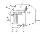
例えば図6に示すように、太陽電池パネル1の下部にレドックスフロー電池2の電解液タンク22を重ねた状態で、両者を建物の屋根4上に設置したとすると、夏季等には電解液タンク22内の電解液の温度上昇によって、レドックスフロー電池2の機能低下を招くおそれがあった。なお、太陽電池パネル1の重量に加えてさらに電解液タンク22の大重量が加わることから、屋根4の強度上、不利となる点も否めない。 For example, as shown in FIG. 6, when the
したがって、従来は、図7に示すように、太陽電池パネル1のみを建物の屋根上に設置し、レドックスフロー電池2は一体として地上3に設置せざるをえなかった。これでは、レドックスフロー電池2の設置のための大スペースが必要とされるため、家庭用や業務用の小規模な建物への適用は困難である。 Therefore, conventionally, as shown in FIG. 7, only the solar battery panel 1 is installed on the roof of the building, and the
本発明は、上記事情に鑑みてなされたものであった、その目的とするところは、家庭用や業務用の小規模な建物への適用が可能なハイブリッド電源システムを提供することである。 The present invention has been made in view of the above circumstances, and an object of the present invention is to provide a hybrid power supply system that can be applied to small buildings for home use and business use.
本発明は、太陽電池パネルとレドックスフロー電池とを備えたハイブリッド電源システムにおいて、レドックスフロー電池は電池反応セルと電解液タンクとが離間配置される分離型のものであって、少なくとも太陽電池パネルの一部は、所定の敷設領域面に支持架台を立設してその頂面をパネル敷設面とした嵩上げ配置部に敷設されるものであり、上記レドックスフロー電池の電池反応セルが、上記嵩上げ配置部の内部に設けられた配置空間内に収納されていることを特徴とするものである。 The present invention relates to a hybrid power supply system including a solar battery panel and a redox flow battery, wherein the redox flow battery is a separated type in which a battery reaction cell and an electrolyte tank are separated from each other, and at least the solar battery panel A part is laid in a raised arrangement portion where a support frame is erected on a predetermined laying area surface and the top surface is a panel laying surface, and the battery reaction cell of the redox flow battery is arranged in the raised arrangement. It is housed in an arrangement space provided inside the part.
請求項2記載の発明のように、上記電池反応セルは、該電池反応セルを空冷するためのファンを備えていることとしてもよい。 As described in the second aspect of the present invention, the battery reaction cell may include a fan for air-cooling the battery reaction cell.
請求項3記載の発明のように、上記太陽電池パネルの敷設領域面が建造物の屋上部分に設定され、上記嵩上げ配置部は、上記屋上部分のそれぞれ所定箇所に立設される複数の縦フレームと、該縦フレーム下側間に架設される支持フレームと、上記縦フレーム上側間に架設されるパネル支持フレームとを組んで構成されることにより、各フレームで区画して上記配置空間を形成しており、上記配置空間内の上記支持フレーム上に上記電池反応セルが取り付けられていることとしてもよい。 According to a third aspect of the present invention, the laying area surface of the solar cell panel is set on a rooftop portion of a building, and the raised arrangement portion is a plurality of vertical frames respectively erected at predetermined positions on the rooftop portion. And a support frame erected between the lower sides of the vertical frames and a panel support frame erected between the upper sides of the vertical frames, thereby partitioning each frame to form the arrangement space. The battery reaction cell may be mounted on the support frame in the arrangement space.
請求項4記載の発明のように、上記電解液タンクは、建造物の下層部もしくは周辺地上部に設けられていることとしてもよい。 According to a fourth aspect of the present invention, the electrolyte tank may be provided in a lower layer portion or a surrounding ground portion of a building.
本発明によれば、太陽電池パネルが太陽光の当たりやすい場所に敷設され、この太陽電池パネルの下部にレドックスフロー電池の電池反応セルが重ねられたとしても、電池反応セル内の電解液保有量は電解液タンク内のそれよりも非常に少量であるので、レドックスフロー電池全体としての電解液の温度上昇は少なくなり、そのレドックスフロー電池の機能低下を招くおそれが少ない。また電池反応セルの重量は、電解液タンクの重量に比べて軽量であるので、建物の強度を低下させるおそれが少ない。 According to the present invention, even if the solar battery panel is laid in a place where it is easily exposed to sunlight, and the battery reaction cell of the redox flow battery is stacked on the lower part of the solar battery panel, the amount of electrolyte contained in the battery reaction cell Is much smaller than that in the electrolytic solution tank, so that the temperature rise of the electrolytic solution as a whole redox flow battery is reduced, and there is little possibility that the function of the redox flow battery is lowered. Further, since the weight of the battery reaction cell is lighter than the weight of the electrolyte tank, there is little risk of reducing the strength of the building.
図1は、本発明の一実施形態に係るハイブリッド電源システムの概念図である。ここでは、主電源としての太陽電池パネル1と、補助電源としてのレドックスフロー電池2と、両電源を屋内電力系統9又は商用電力系統10に接続するための交直変換装置(パワーコンディショナ)6とを備えたハイブリッド電源システムが構成されている。 FIG. 1 is a conceptual diagram of a hybrid power supply system according to an embodiment of the present invention. Here, a solar cell panel 1 as a main power source, a
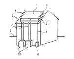
本発明は、このシステムの配置を特徴とするもので、例えば図2に示すように、電池反応セル21と電解液タンク22とに分離してなる、いわゆる分離型のレドックスフロー電池2の電解液タンク22を地上(建造物の周辺地上部)3に配置するとともに、一般家庭の家の屋根(建造物の屋上部分)4上に設置される平板状の太陽電池パネル1の下部に電池反応セル21を配置する。 The present invention is characterized by the arrangement of this system. For example, as shown in FIG. 2, the electrolytic solution of a so-called separation type
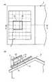
図3は、その屋根上の配置の一例を示すものであって、(A)は平面図、(B)はX−X線断面図である。図3に示すように、一般家庭の家の屋根4は傾斜しているものが多く、その傾斜面(好ましくは南面)を嵩上げして、その嵩上げ配置部5に太陽電池パネル1が配置されることが多い。嵩上げ配置部5は、屋根4の図示しない強度部材からフレーム構造の支持架台51が立設されている。 3A and 3B show an example of the arrangement on the roof, where FIG. 3A is a plan view and FIG. 3B is a sectional view taken along line XX. As shown in FIG. 3, the
この支持架台51は、太陽電池パネル1の敷設領域面となる屋根4の例えば南面上の4角付近にそれぞれ立設される縦フレーム511と、この縦フレーム511の下側間に架設され、屋根4の傾斜にほぼ沿った態様の支持フレーム512と、縦フレーム511の上端間に架設されるパネル支持フレーム513とを組んで構成されている。ここでは、支持フレーム512は屋根4に沿って傾斜させているが、パネル支持フレーム513は一年を通じての太陽光の当たり具合を考慮して支持フレーム512よりも緩やかに傾斜させている。そして、このパネル支持フレーム513上のパネル敷設面(支持架台51の頂面)514に太陽電池パネル1の市販モジュールが敷設される。 The
また、各フレーム511〜513で区画されて所定の大きさの配置空間50が形成され、この配置空間50内の支持フレーム512上の平面視略中央に電池反応セル21のセルスタックと空冷用ファン24とが一体化して取り付けられる。したがって、屋根4上には、電池反応セル21等は直置きされず、防水上有利であるとともに、屋根4上の雨水の流れを妨害することもない。そして、上記配置空間50の大きさを確保することで、電池反応セル21がより通風されやすくなる。 Further, an
また、支持フレーム512は屋根4に沿って傾斜させているので、電池反応セル21のセルスタックも傾斜状態となっている。かかる傾斜状態で電池反応セル21のセルスタックを配置すると、それを縦配置や水平配置した場合に比べて、太陽電池パネル1の高さを極力抑えることができる。また、このように電池反応セル21のセルスタックを傾斜状態で配置したとしても、電解液はポンプ25で圧送されているので、そのセルスタック内がエアロックするおそれはない(後述する図4参照)。 In addition, since the
一方、地上3には電解液タンク22と、ポンプ25と、交直変換装置(インバータ)6とが設置されている。この電解液タンク22と上記電池反応セル21との間にはポンプ25で電解液を圧送するための2対の往復配管7が配設されており、交直変換装置6と上記太陽電池パネル1及び電池反応セル21との間には電流を流すための2系統の電線8が導設されている。交直変換装置6は、上述したように屋内電力系統9と商用電力系統10とに接続されている。 On the other hand, an
このようにして、屋根4上の機器を一体化して支持架台51に取り付けることで、その強度を確保する一方、地上3にメンテナンスを要する機器を集中させることとしている。したがって、例えば長期にわたるシステム停止時等には、電解液タンク22内を窒素ガスパージしておくのが好ましいが、その電解液タンク22が地上3にあることで、高所作業がなくなり、システムの保守が容易となる。 In this way, the devices on the
本システムの配置の成立要件を検討すると、以下のようになる。 When the requirements for establishment of this system are examined, it is as follows.
標準家庭の電力需要の実績から太陽電池パネル1の電気出力は、4.5kW×8h=36kWhであるとすると、太陽電池パネル1は、約50m2(10m×5m)の面積が必要とされる。したがって、この面積以上の屋根4の広さがあればよいことになる。 Assuming that the electrical output of the solar cell panel 1 is 4.5 kW × 8 h = 36 kWh based on the actual power demand of a standard home, the solar cell panel 1 requires an area of about 50 m 2 (10 m × 5 m). Therefore, it suffices if the
交直変換装置6は、レドックスフロー電池2と兼用タイプとして、交流単相3線200V・100V/直流200Vの入出力が可能なものとする。なお、オール電化住宅では直直変換装置とされる。 The AC /
レドックスフロー電池2の電気出力は、太陽電池パネル1の電気出力と一致させると、4.5kW×8h=36kWhであって、この場合の電解液タンク22の体積は、約5m3となり、比重1.4で重量約7.0トンとなる。 The electrical output of the
そして、電解液タンク22を地上設置すると、約4m2の面積が必要とされる。また、電池反応セル21は、15セルのスタックであって、縦1m×横1m×高さ0.5mの大きさとなる。したがって、このセルスタックの屋根占有面積は約1.0m2(1.0m×1.0m)となり、その重量は約0.5トンとなる。 When the
地上3の電解液タンク22から電解液を屋根4上の電池反応セル21に圧送するためにポンプ25が使用されるが、その必要とされるポンプ動力Pは、その電解液流量Qとヘッド差Hとから以下のように求めることができる。 A pump 25 is used to pump the electrolyte from the
P=9.8QH
=9.8×0.04(m3)/60×15m
=0.1(kWh)
=100(W)
ここで、従来例で述べた各配置と比較すると、次のようになる。P = 9.8QH
= 9.8 × 0.04 (m3) / 60 × 15 m
= 0.1 (kWh)
= 100 (W)
Here, it is as follows when compared with each arrangement described in the conventional example.
すなわち、図6のように屋根4上の太陽電池パネル1の下部にレドックスフロー電池2の電解液タンク22を配置するとともに、地上3に電池反応セル21を配置した場合には、ポンプ動力は本システムと同じ100Wとなる。しかし、屋根荷重は7.0トンとなって、本システムの0.5トンに比べてかなり重くなる。その一方、地上占有面積は1m2で済み、本システムの4m2に比べて少なくて済む。 That is, when the
また、図7のように屋根4上に太陽電池パネル1のみを設置するとともに、地上3にレドックスフロー電池2の全体を設置した場合には、ポンプ動力は20Wとなって、本システムよりも小さくなり、屋根荷重の増加もない。しかし、地上占有面積は5m2となり、本システムよりも大きくなる。かかる差がたとえ僅かなものであっても、本システムの配置の成立性を大きく左右する。 Moreover, when only the solar cell panel 1 is installed on the
引き続き、本システムの配置を可能とするレドックスフロー電池2の構造を説明する。 Next, the structure of the
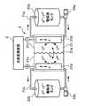
レドックスフロー電池2の電池反応セル21は、複数の単セルを積層したスタック構造となっている。各単セルは、図4に示すように、例えばイオン交換膜からなる隔膜21aにより中央部で仕切られており、一方側が負電極21bを収容するセル負極側21c、他方側が正電極21dを収容するセル正極側21eを構成している。この隔膜21aの使用温度の制限から、電解液の温度を40℃以下に保持することが好ましい。 The
そこで、本システムの配置では、電池反応セル21が太陽電池パネル1によって直射日光から遮られるとともに、その電池反応セル21に近接して配備された冷却用ファン24で電池反応セル21のセルスタックを強制的に空冷するようになっている。この冷却効率を向上させるために、熱交換器等を設けてもよい。 Therefore, in the arrangement of this system, the
電解液タンク22は、さらに負極液タンク22aと、正極液タンク22bとからなっており、上記したポンプ25、配管7等も全て2系統となっている。 The
すなわち、電池反応セル21のセル負極側21cと負極液タンク22aとは負極液循環ライン71aで連結され、セル正極側21eと正電極タンク22bとは正電極液循環ライン71bで連結されている。負極液循環ライン71aには負極液循環用ポンプ25aが介装されており、二価のバナジウム(V2+)と、三価のバナジウム(V3+)とを硫酸水溶液に溶解させた負極液を循環させるようになっている。正極液循環ライン71bには正極液循環用ポンプ25bが介装されており、五価のバナジウム(V5+)と、四価のバナジウム(V4+)とを硫酸水溶液に溶解させた正極液を循環させるようになっている。That is, the cell
以下、本システムの全体の動作を、その配置による特有の動作を含めて説明する。 Hereinafter, the overall operation of the present system will be described including the specific operation depending on the arrangement.
上記図1において、補助電源としてのレドックスフレー電池2は予め安価な深夜電力で充電しておくようになっている。すなわち、商用電力系統10からの深夜電力(交流)が交直変換装置6で直流に変換されて、この直流が電池反応セル21の両電極に供給される。このとき、負極液タンク22aに蓄えられた負極液が負極液循環用ポンプ25aによりセル負極側21cに圧送され、負電極21bにおいて電子(e-)を受け取り、三価のバナジウム(V3+)が二価のバナジウム(V2+)に還元された後に、負極液タンク22aに回収される。他方、正極液タンク22bに蓄えられた正極液が正極液循環用ポンプ25bによりセル正極側21eに圧送され、正電極21dにおいて電子(e-)を放出し、四価のバナジウム(V4+)が五価のバナジウム(V5+)に酸化された後に、正極液タンク22bに回収される。このようにして、レドックスフロー電池2は充電状態とされる。In FIG. 1, the
一方、主電源としての太陽電池パネル1は、日当たりのよい屋根4上に設置されているので、天気の良好な昼間等には太陽光を受けて電力(直流)を発生する。この発生した直流を、交直変換装置6で交流に変換して屋内電力系統9に供給し、屋内での電力需要を賄うことができる。そして、太陽電池パネル1での発電量がさらに増加して屋内での使用電力を超える電力が発生すると、その余剰電力を商用電力系統10を介して電力会社に売電することもできる。 On the other hand, since the solar cell panel 1 as the main power source is installed on the
このときには、レドックスフロー電池2の上記充電状態を維持する必要がある。本システムの配置では、電池反応セル21は太陽電池パネル1の下部にあってファン24で空冷されており、しかも電池反応セル21内の電解液保有量は電解液タンク22内のそれよりも非常に少量である。したがって、レドックスフロー電池2全体としての電解液の温度上昇は少なくなる結果、レドックスフロー電池2の機能低下をきたさず、上記充電状態を維持することができる。 At this time, it is necessary to maintain the charged state of the
一方、悪天候や夜間等には太陽電池パネル1での発電量が著しく減少して屋内での電力需要を賄うことができなくなる。この場合には、補助電源としてのレドックスフレー電池2から放電される電力が使用される。すなわち、正極液タンク22bに蓄えられた正極液が正極液循環用ポンプ25bによりセル正極側21eに圧送され、正電極21dにおいて電子(e-)を受け取り、五価のバナジウム(V5+)が四価のバナジウム(V4+)に還元された後に、正極液タンク22bに回収される。他方、負極液タンク22aに蓄えられた負極液が負極液循環用ポンプ25aによりセル負極側21cに圧送され、負電極21bにおいて電子(e-)を放出し、二価のバナジウム(V2+)が三価のバナジウム(V3+)に酸化された後に、負極液タンク22aに回収される。このようにして、レドックスフロー電池2は放電状態とされる。この放電された電力(直流)が交直変換装置6で交流に変換されて屋内電力系統9に供給される。それでも電力不足となる場合には、その不足分を商用電力系統10から供給される商用電力で賄うこともできる。On the other hand, in bad weather, at night, etc., the amount of power generated by the solar cell panel 1 is significantly reduced, making it impossible to cover indoor power demand. In this case, electric power discharged from the
以上説明したように、本実施形態のシステムによれば、太陽電池パネル1が太陽光の当たりやすい場所に敷設され、この太陽電池パネル1の下部にレドックスフロー電池2の電池反応セル21が重ねられたとしても、レドックスフロー電池2の機能低下を招くおそれが少ない。また、電池反応セル21の重量は、電解液タンク22の重量に比べて軽量であるので、建物の強度を低下させるおそれも少ない。また、本システムは新築の家はもちろんのこと、既存の家にも容易に搭載できる。 As described above, according to the system of the present embodiment, the solar battery panel 1 is laid in a place where the sunlight is easily hit, and the
なお、上記実施形態では、レドックスフロー電電池2を補助電源として使用しており、太陽電池パネル1で発電した電力をレドックスフロー電池2に蓄電するようにはなっていないが、太陽電池パネル1で発電した電力を直接レドックスフロー電池2に蓄電するような構成にしてもよい。 In the above embodiment, the
また、上記実施形態では、平板状の太陽電池パネル1の下部中央にレドックスフロー電池2の電池反応セル21を配設したが、図5に示すように、太陽電池パネル1の中央部だけを持ち上げて、そのパネル下に電池反応セル21を配設することもできる。その場合には太陽電池パネル1の中央部以外の高さを抑えることができるので、強度上さらに有利な構造が得られる。この持ち上げる部位は、太陽電池パネル1の範囲内であればどこでもよい。太陽電池パネル1の形状も四角形とは限らず、例えば円形やその他の形状のものがあるが、その場合でも上記と同様な配置ができる。 Moreover, in the said embodiment, although the
また、上記実施形態では、レドックスフロー電池2の電池反応セル21をファン24で強制冷却しているが、太陽電池パネル1下の通風状態によっては、自然冷却で充分な場合もある。 Moreover, in the said embodiment, although the
また、上記実施形態では、本システムの太陽電池パネル1とレドックスフロー電池2の電池反応セル21を搭載するための屋上部分を有する建造物として、傾斜屋根を有する一般家庭の家について説明したが、フラットな屋根を有する家や事業用のビルであってもよい。また、レドックスフロー電池2の電解液タンク22の設置場所としては、建造物の周辺地上部の代わりに建造物の下層部であってもよい。 Moreover, although the said embodiment demonstrated the general household house which has an inclined roof as a building which has a roof part for mounting the solar cell panel 1 of this system and the
1 太陽電池パネル
2 レドックスフロー電池
21 電池反応セル
22 電解液タンク
24 ファン
25 ポンプ
3 地上(建造物の周辺地上部)
4 屋根(建造物の屋上部分)
5 嵩上げ配置部
50 配置空間
51 支持架台
511 縦フレーム
512 支持フレーム
513 パネル支持フレーム
514 パネル敷設面(支持架台の頂面)
6 交直変換装置
7 配管
8 電線DESCRIPTION OF SYMBOLS 1
4 Roof (the rooftop part of the building)
DESCRIPTION OF
6 AC /
Claims (4)
Translated fromJapaneseレドックスフロー電池は電池反応セルと電解液タンクとが離間配置される分離型のものであって、
少なくとも太陽電池パネルの一部は、所定の敷設領域面に支持架台を立設してその頂面をパネル敷設面とした嵩上げ配置部に敷設されるものであり、
上記レドックスフロー電池の電池反応セルが、上記嵩上げ配置部の内部に設けられた配置空間内に収納されていることを特徴とするハイブリッド電源システム。In a hybrid power supply system including a solar battery panel and a redox flow battery,
The redox flow battery is a separate type in which the battery reaction cell and the electrolyte tank are separated from each other,
At least a part of the solar cell panel is laid in a raised arrangement portion in which a support frame is erected on a predetermined laying area surface and the top surface is a panel laying surface,
The hybrid power supply system, wherein the battery reaction cell of the redox flow battery is accommodated in an arrangement space provided inside the raised arrangement part.
上記嵩上げ配置部は、上記屋上部分のそれぞれ所定箇所に立設される複数の縦フレームと、該縦フレーム下側間に架設される支持フレームと、上記縦フレーム上側間に架設されるパネル支持フレームとを組んで構成されることにより、各フレームで区画して上記配置空間を形成しており、
上記配置空間内の上記支持フレーム上に上記電池反応セルが取り付けられていることを特徴とする請求項1又は2記載のハイブリッド電源システム。The laying area surface of the solar cell panel is set on the rooftop part of the building,
The raised arrangement portion includes a plurality of vertical frames erected at predetermined positions on the rooftop portion, a support frame erected between the lower sides of the vertical frames, and a panel support frame erected between the upper sides of the vertical frames. And the above-mentioned arrangement space is formed by dividing each frame.
The hybrid power supply system according to claim 1, wherein the battery reaction cell is mounted on the support frame in the arrangement space.
Priority Applications (1)
| Application Number | Priority Date | Filing Date | Title |
|---|---|---|---|
| JP2004049021AJP2005243326A (en) | 2004-02-25 | 2004-02-25 | Hybrid power supply system |
Applications Claiming Priority (1)
| Application Number | Priority Date | Filing Date | Title |
|---|---|---|---|
| JP2004049021AJP2005243326A (en) | 2004-02-25 | 2004-02-25 | Hybrid power supply system |
Publications (1)
| Publication Number | Publication Date |
|---|---|
| JP2005243326Atrue JP2005243326A (en) | 2005-09-08 |
Family
ID=35024847
Family Applications (1)
| Application Number | Title | Priority Date | Filing Date |
|---|---|---|---|
| JP2004049021AWithdrawnJP2005243326A (en) | 2004-02-25 | 2004-02-25 | Hybrid power supply system |
Country Status (1)
| Country | Link |
|---|---|
| JP (1) | JP2005243326A (en) |
Cited By (8)
| Publication number | Priority date | Publication date | Assignee | Title |
|---|---|---|---|---|
| JP2011522404A (en)* | 2008-05-30 | 2011-07-28 | アラン エドガー、ロス | 3D solar cell array |
| US8785023B2 (en) | 2008-07-07 | 2014-07-22 | Enervault Corparation | Cascade redox flow battery systems |
| US8906529B2 (en) | 2008-07-07 | 2014-12-09 | Enervault Corporation | Redox flow battery system for distributed energy storage |
| US8916281B2 (en) | 2011-03-29 | 2014-12-23 | Enervault Corporation | Rebalancing electrolytes in redox flow battery systems |
| US8980484B2 (en) | 2011-03-29 | 2015-03-17 | Enervault Corporation | Monitoring electrolyte concentrations in redox flow battery systems |
| KR101716391B1 (en)* | 2016-05-30 | 2017-03-14 | 한국기계연구원 | Redox flow battery |
| WO2019087366A1 (en)* | 2017-11-02 | 2019-05-09 | 住友電気工業株式会社 | Redox flow battery |
| EP3447834A4 (en)* | 2016-04-21 | 2020-01-08 | Sumitomo Electric Industries, Ltd. | CONTAINER-LIKE BATTERY |
- 2004
- 2004-02-25JPJP2004049021Apatent/JP2005243326A/ennot_activeWithdrawn
Cited By (15)
| Publication number | Priority date | Publication date | Assignee | Title |
|---|---|---|---|---|
| JP2011522404A (en)* | 2008-05-30 | 2011-07-28 | アラン エドガー、ロス | 3D solar cell array |
| US8785023B2 (en) | 2008-07-07 | 2014-07-22 | Enervault Corparation | Cascade redox flow battery systems |
| US8906529B2 (en) | 2008-07-07 | 2014-12-09 | Enervault Corporation | Redox flow battery system for distributed energy storage |
| US8916281B2 (en) | 2011-03-29 | 2014-12-23 | Enervault Corporation | Rebalancing electrolytes in redox flow battery systems |
| US8980484B2 (en) | 2011-03-29 | 2015-03-17 | Enervault Corporation | Monitoring electrolyte concentrations in redox flow battery systems |
| TWI712205B (en)* | 2016-04-21 | 2020-12-01 | 日商住友電氣工業股份有限公司 | Cartridge battery |
| US11522209B2 (en) | 2016-04-21 | 2022-12-06 | Sumitomo Electric Industries, Ltd. | Container-type battery |
| EP3447834A4 (en)* | 2016-04-21 | 2020-01-08 | Sumitomo Electric Industries, Ltd. | CONTAINER-LIKE BATTERY |
| KR101716391B1 (en)* | 2016-05-30 | 2017-03-14 | 한국기계연구원 | Redox flow battery |
| WO2019087366A1 (en)* | 2017-11-02 | 2019-05-09 | 住友電気工業株式会社 | Redox flow battery |
| JPWO2019087366A1 (en)* | 2017-11-02 | 2020-09-24 | 住友電気工業株式会社 | Redox flow battery |
| US10950879B2 (en) | 2017-11-02 | 2021-03-16 | Sumitomo Electric Industries, Ltd. | Redox flow battery |
| CN109997269B (en)* | 2017-11-02 | 2022-03-01 | 住友电气工业株式会社 | Redox flow battery |
| TWI785084B (en)* | 2017-11-02 | 2022-12-01 | 日商住友電氣工業股份有限公司 | Redox flow battery |
| CN109997269A (en)* | 2017-11-02 | 2019-07-09 | 住友电气工业株式会社 | Redox flow batteries |
Similar Documents
| Publication | Publication Date | Title |
|---|---|---|
| CN104904112B (en) | The building exterior material that panel with solar module is constituted | |
| KR20080017121A (en) | Building Exterior Substitute Solar Module Panel | |
| JP2005243326A (en) | Hybrid power supply system | |
| KR102221157B1 (en) | A cooling system for solar module | |
| US9570772B2 (en) | Power production apparatus and structure block system for water storage facility | |
| JP6058746B1 (en) | Container assembly for hydrogen system | |
| JP5000013B2 (en) | Electronic equipment storage unit | |
| JP4079347B2 (en) | Power generator | |
| CN113629731A (en) | Wind-solar combined stable water electrolysis hydrogen production system | |
| JP5318198B2 (en) | Electronic equipment storage unit | |
| CN215817635U (en) | Wind-solar hybrid power supply system | |
| US20250300275A1 (en) | Secondary battery | |
| JP2003008045A (en) | Solar cell array and method for constructing the same | |
| CN206498242U (en) | A kind of landscape awning and mobile charging system | |
| CN216216089U (en) | Energy storage system and energy storage power station | |
| JP2002076407A (en) | Photovoltaic power generator utilizing outdoor machine of air-conditioner | |
| JP2002033502A (en) | Solar power system | |
| JP5567808B2 (en) | Heat pump system | |
| CN215817552U (en) | Wind-solar energy storage micro-grid system for transformer substation | |
| KR101358730B1 (en) | Structure block for water storage facility with power generating function | |
| CN215956282U (en) | Box type rectification power supply device for electrolytic hydrogen production | |
| CN214958853U (en) | Outdoor intelligent box-type pump room with automatic cleaning and power generation functions | |
| CN217486215U (en) | A photovoltaic integrated charging shed for battery cars | |
| US12320553B1 (en) | Storage shed with integrated solar roof | |
| US20250023514A1 (en) | Self sufficient energy supplied system for generating atmospheric water and method to control the system |
Legal Events
| Date | Code | Title | Description |
|---|---|---|---|
| A300 | Application deemed to be withdrawn because no request for examination was validly filed | Free format text:JAPANESE INTERMEDIATE CODE: A300 Effective date:20070501 |