JP2005242598A - Information processing system and method, and computer program - Google Patents
Information processing system and method, and computer programDownload PDFInfo
- Publication number
- JP2005242598A JP2005242598AJP2004050651AJP2004050651AJP2005242598AJP 2005242598 AJP2005242598 AJP 2005242598AJP 2004050651 AJP2004050651 AJP 2004050651AJP 2004050651 AJP2004050651 AJP 2004050651AJP 2005242598 AJP2005242598 AJP 2005242598A
- Authority
- JP
- Japan
- Prior art keywords
- information processing
- public area
- processing apparatus
- address
- storage space
- Prior art date
- Legal status (The legal status is an assumption and is not a legal conclusion. Google has not performed a legal analysis and makes no representation as to the accuracy of the status listed.)
- Abandoned
Links
Images


Classifications
- G—PHYSICS
- G06—COMPUTING OR CALCULATING; COUNTING
- G06F—ELECTRIC DIGITAL DATA PROCESSING
- G06F15/00—Digital computers in general; Data processing equipment in general
- G06F15/16—Combinations of two or more digital computers each having at least an arithmetic unit, a program unit and a register, e.g. for a simultaneous processing of several programs
- G—PHYSICS
- G06—COMPUTING OR CALCULATING; COUNTING
- G06F—ELECTRIC DIGITAL DATA PROCESSING
- G06F9/00—Arrangements for program control, e.g. control units
- G06F9/06—Arrangements for program control, e.g. control units using stored programs, i.e. using an internal store of processing equipment to receive or retain programs
- G06F9/46—Multiprogramming arrangements
- G06F9/50—Allocation of resources, e.g. of the central processing unit [CPU]
- G06F9/5005—Allocation of resources, e.g. of the central processing unit [CPU] to service a request
- G06F9/5011—Allocation of resources, e.g. of the central processing unit [CPU] to service a request the resources being hardware resources other than CPUs, Servers and Terminals
- G06F9/5016—Allocation of resources, e.g. of the central processing unit [CPU] to service a request the resources being hardware resources other than CPUs, Servers and Terminals the resource being the memory
- G—PHYSICS
- G06—COMPUTING OR CALCULATING; COUNTING
- G06F—ELECTRIC DIGITAL DATA PROCESSING
- G06F12/00—Accessing, addressing or allocating within memory systems or architectures
- G—PHYSICS
- G06—COMPUTING OR CALCULATING; COUNTING
- G06F—ELECTRIC DIGITAL DATA PROCESSING
- G06F12/00—Accessing, addressing or allocating within memory systems or architectures
- G06F12/02—Addressing or allocation; Relocation
- G06F12/08—Addressing or allocation; Relocation in hierarchically structured memory systems, e.g. virtual memory systems
- G06F12/10—Address translation
- G06F12/1027—Address translation using associative or pseudo-associative address translation means, e.g. translation look-aside buffer [TLB]
- G06F12/1036—Address translation using associative or pseudo-associative address translation means, e.g. translation look-aside buffer [TLB] for multiple virtual address spaces, e.g. segmentation
- G—PHYSICS
- G06—COMPUTING OR CALCULATING; COUNTING
- G06F—ELECTRIC DIGITAL DATA PROCESSING
- G06F12/00—Accessing, addressing or allocating within memory systems or architectures
- G06F12/02—Addressing or allocation; Relocation
- G06F12/08—Addressing or allocation; Relocation in hierarchically structured memory systems, e.g. virtual memory systems
- G06F12/10—Address translation
- G06F12/109—Address translation for multiple virtual address spaces, e.g. segmentation
- G—PHYSICS
- G06—COMPUTING OR CALCULATING; COUNTING
- G06F—ELECTRIC DIGITAL DATA PROCESSING
- G06F12/00—Accessing, addressing or allocating within memory systems or architectures
- G06F12/14—Protection against unauthorised use of memory or access to memory
- G06F12/1458—Protection against unauthorised use of memory or access to memory by checking the subject access rights
- G06F12/1466—Key-lock mechanism
- G06F12/1475—Key-lock mechanism in a virtual system, e.g. with translation means
Landscapes
- Engineering & Computer Science (AREA)
- Theoretical Computer Science (AREA)
- Physics & Mathematics (AREA)
- General Engineering & Computer Science (AREA)
- General Physics & Mathematics (AREA)
- Software Systems (AREA)
- Computer Hardware Design (AREA)
- Information Transfer Between Computers (AREA)
- Storage Device Security (AREA)
- Memory System (AREA)
- Information Retrieval, Db Structures And Fs Structures Therefor (AREA)
Abstract
Description
Translated fromJapanese本発明は、ネットワーク接続された2以上の機器間における動作を連携させる情報処理システム及び情報処理方法、並びにコンピュータ・プログラムに係り、特に、ネットワークで接続された2以上の機器間における動作を連携させる情報処理システム及び情報処理方法、並びにコンピュータ・プログラムに関する。 The present invention relates to an information processing system, an information processing method, and a computer program for coordinating operations between two or more devices connected to a network, and more particularly, to coordinate operations between two or more devices connected via a network. The present invention relates to an information processing system, an information processing method, and a computer program.
さらに詳しくは、本発明は、ネットワーク接続された複数の機器が協調動作により分散処理を行なうことで、仮想的に1台の機器として動作する情報処理システム及び情報処理方法、並びにコンピュータ・プログラムに係り、特に、ネットワーク経由で連携動作する情報処理装置の間で記憶空間の共有を行なう情報処理システム及び情報処理方法、並びにコンピュータ・プログラムに関する。 More specifically, the present invention relates to an information processing system, an information processing method, and a computer program that virtually operate as a single device by a plurality of devices connected to a network performing distributed processing through cooperative operation. In particular, the present invention relates to an information processing system, an information processing method, and a computer program that share a storage space between information processing apparatuses that operate in cooperation via a network.
複数のコンピュータ同士をネットワークで相互接続することにより、情報資源の共有、ハードウェア資源の共有、複数のユーザ間でのコラボレーションが実現することが知られている。コンピュータ間の接続メディアとして、LAN(Local Area Network)、WAN(Wide Area Network)、インターネットなどさまざまである。 It is known that information resources can be shared, hardware resources can be shared, and collaboration among a plurality of users can be realized by interconnecting a plurality of computers via a network. As connection media between computers, there are various types such as a LAN (Local Area Network), a WAN (Wide Area Network), and the Internet.
特に最近では、一般家庭内にもコンピュータやネットワークなどの技術が深く浸透してきている。家庭内のパーソナル・コンピュータやPDA(Personal Digital Assistants)などの情報機器、さらにはテレビ受像機やビデオ再生装置などAV機器や、各種の情報家電、CE(Consumer Electronics)機器などがホームネットワーク経由で相互接続されている。また、このようなホームネットワークは、多くの場合、ルータ経由でインターネットを始めとする外部の広域ネットワークに相互接続されている。 Recently, in particular, technologies such as computers and networks have deeply penetrated into ordinary homes. Information devices such as personal computers and PDAs (Personal Digital Assistants) in the home, AV devices such as television receivers and video playback devices, various information appliances, and CE (Consumer Electronics) devices are mutually connected via the home network. It is connected. Such home networks are often interconnected to external wide area networks such as the Internet via routers.
このようにホームネットワーク上に複数のAV機器が接続されるという利用形態が想定されるが、いままでは、AV機器間で充分な連携がなされていない、という問題がある。 In this way, a usage form in which a plurality of AV devices are connected to the home network is assumed. However, until now, there is a problem that sufficient cooperation between AV devices has not been achieved.
このような問題に対し、最近では、ネットワーク上の機器同士を連携させるために、機器の協調動作により高い演算性能を実現するというグリッドコンピューティング技術に関する研究開発が進められている(例えば、特許文献1〜5を参照のこと)。 Recently, research and development related to grid computing technology that realizes high computing performance by cooperative operation of devices in order to link devices on a network in order to cooperate with each other (for example, patent documents) 1-5).
このグリッドコンピューティング技術によれば、ネットワーク上の複数の情報処理装置が強調動作して分散処理を行ない、ユーザからは仮想的に1台の情報処理装置として動作することができる。 According to this grid computing technology, a plurality of information processing apparatuses on the network perform an emphasis operation to perform distributed processing, and can operate virtually as one information processing apparatus from the user.
例えば、録画予約機能を持つ複数台の情報処理装置がネットワーク上に接続されている場合、録画予約の連携動作を実現することができる。すなわち、複数台の情報処理装置がホームネットワーク経由で録画予約の動作を連携させている場合、ホームネットワーク上では仮想的に1台の録画機器として動作する。そして、ユーザは、いずれかの機器のユーザ・インターフェースを用いて、ホームネットワークに接続されている任意の機器を用いて録画予約を行なうことができる。 For example, when a plurality of information processing apparatuses having a recording reservation function are connected to a network, a recording reservation cooperation operation can be realized. In other words, when a plurality of information processing apparatuses link recording reservation operations via a home network, the information processing devices virtually operate as one recording device on the home network. Then, the user can make a recording reservation using any device connected to the home network using the user interface of any device.
さらにこのような録画予約機能の連携により、予約時間が重複した番組(いわゆる裏番組)を同時録画することが可能である。同様に、記録したコンテンツの再生動作を複数の機器間で連携させ、同時・同期的なコンテンツ再生を実現することができる。このコンテンツ再生機能の連携により、別々の機器で記録されたコンテンツの再生を同時、同期的に進行させることにより、コンテンツ再生においてチャンネル切り換えの概念を導入することができる。 Furthermore, by cooperation of such a recording reservation function, it is possible to simultaneously record programs with overlapping reservation times (so-called back programs). Similarly, the playback operation of the recorded content can be linked between a plurality of devices, and simultaneous and synchronous content playback can be realized. By cooperating with the content reproduction function, the concept of channel switching can be introduced in content reproduction by simultaneously and synchronously reproducing the content recorded by different devices.
このような仮想的な1台の機器によれば、1台の機器のハードウェア資源や処理能力だけではユーザからの要求に応じることができない場合であっても、ネットワーク上で連携・協調動作する他の機器における余剰の処理能力を活用することで、ユーザの要求に応じることができ、さらに通常の1台の機器では現実的ではないサービスを実現することができる。 According to such a single virtual device, even if the hardware resource and processing capability of the single device cannot meet the request from the user, they cooperate and operate on the network. By utilizing the surplus processing capacity of other devices, it is possible to meet the user's request and to realize a service that is not realistic with one normal device.
他方、このような仮想的な1台の情報処理システムにおいては、システムを構成する情報処理装置毎にハードウェア構成や処理能力、さらには現在の処理負荷は区々であり、余剰の処理能力が不均一である、という問題がある。 On the other hand, in such a virtual information processing system, the hardware configuration and processing capacity of each information processing apparatus constituting the system, and further, the current processing load varies, and there is an excess processing capacity. There is a problem of non-uniformity.
このような場合、ネットワーク経由で連携するある情報処理装置においては余剰の処理能力がなく、且つメモリ資源が欠乏している一方で、他の情報処理装置では余剰の処理能力があり、オペレーティングシステムにおいて未使用のメモリ領域が十分に残っている、という無駄な状況が生じ得る。 In such a case, an information processing device linked via a network does not have surplus processing capability and lacks memory resources, while other information processing devices have surplus processing capability, There may be a useless situation in which a sufficient unused memory area remains.
例えば、LAN回線に接続された複数のコンピュータ間におけるメモリの融通使用を可能とし、メモリ資源の有効活用とスワッピング処理の高速化を実現するメモリ共有方式について提案がなされている(例えば、特許文献6を参照のこと)。 For example, there has been proposed a memory sharing method that enables the flexible use of memory between a plurality of computers connected to a LAN line, and realizes effective use of memory resources and high speed of swapping processing (for example, Patent Document 6). checking).
この場合、メモリ要求コンピュータからのメモリ割当て要求に応じてメモリ割当てを行なう共有メモリを備えたメモリ管理コンピュータをLAN上にあらかじめ設置するものである。言い換えれば、メモリ要求コンピュータとメモリ管理コンピュータは、メモリ割当て要求に関する手続き以外はそれぞれ独立して動作するものであり、ネットワーク上の各情報処理装置が連携して仮想的に1台の情報処理装置として動作するグリッドコンピューティングとは相違する。 In this case, a memory management computer having a shared memory for performing memory allocation in response to a memory allocation request from the memory requesting computer is installed on the LAN in advance. In other words, the memory requesting computer and the memory management computer operate independently of each other except for the procedure related to the memory allocation request, and each information processing device on the network cooperates as a single information processing device. It is different from grid computing that operates.
また、この場合、メモリ要求コンピュータ側では、他のコンピュータから割り当てられた共有メモリを自分のメモリ空間に割り当てるものではなく、このため共有メモリへのアクセスはあくまでLAN経由でのネットワーク動作に他ならない。すなわち、メモリ要求コンピュータ側では、共有メモリへのアクセスを自分のメインメモリへのアクセスと透過的に行なうことができない。 In this case, the memory requesting computer does not allocate the shared memory allocated from another computer to its own memory space. Therefore, access to the shared memory is nothing but a network operation via the LAN. That is, on the memory requesting computer side, access to the shared memory cannot be performed transparently with access to its own main memory.
本発明の目的は、ネットワーク接続された複数の機器が協調動作により分散処理を行なうことで、仮想的に1台の機器として動作することができる、優れた情報処理システム及び情報処理方法、並びにコンピュータ・プログラムを提供することにある。 An object of the present invention is to provide an excellent information processing system, information processing method, and computer capable of operating virtually as a single device by performing distributed processing by a plurality of devices connected to a network through cooperative operation.・ To provide a program.
本発明のさらなる目的は、ネットワーク経由で連携動作する情報処理装置の間で記憶空間の共有を行なうことができる、優れた情報処理システム及び情報処理方法、並びにコンピュータ・プログラムを提供することにある。 A further object of the present invention is to provide an excellent information processing system, information processing method, and computer program capable of sharing a storage space between information processing apparatuses that operate in cooperation via a network.
本発明は、上記課題を参酌してなされたものであり、その第1の側面は、ネットワーク接続される複数の情報処理装置の連携動作により仮想的に1台の仮想情報処理装置として動作する情報処理システムであって、
各情報処理装置は物理記憶装置を備え、
少なくとも1つの情報処理装置は、自装置の物理記憶装置の物理記憶空間上に他の情報処理装置の使用を許可する公開領域を形成し、他の情報処理装置からの公開領域の使用要求に応じて使用を許可する、
ことを特徴とする情報処理システムである。The present invention has been made in consideration of the above problems, and a first aspect of the present invention is information that virtually operates as a single virtual information processing device by a cooperative operation of a plurality of information processing devices connected to a network. A processing system,
Each information processing device includes a physical storage device,
At least one information processing apparatus forms a public area that permits the use of another information processing apparatus in the physical storage space of its own physical storage apparatus, and responds to requests for use of the public area from other information processing apparatuses Allow use,
An information processing system characterized by this.
但し、ここで言う「システム」とは、複数の装置(又は特定の機能を実現する機能モジュール)が論理的に集合した物のことを言い、各装置や機能モジュールが単一の筐体内にあるか否かは特に問わない。 However, “system” here refers to a logical collection of a plurality of devices (or functional modules that realize specific functions), and each device or functional module is in a single housing. It does not matter whether or not.
本発明に係る情報処理システムは、具体的には、ネットワーク接続される複数の情報処理装置の連携動作により仮想的に1台の仮想情報処理装置として動作する。そして、仮想情報処理装置を構成する少なくとも1つの情報処理装置は、自装置の物理記憶装置の物理記憶空間上に他の情報処理装置の使用を許可する公開領域を形成する。ここで言う物理記憶装置には、メインメモリやその他のローカルメモリ、ハードディスクなどの外部記憶装置、さらには自装置にローカル接続される各機器への入出力を割り当てたI/O空間が含まれ、連携動作を行なう情報処理装置の間で、これらの情報資源を共有することが可能となる。 Specifically, the information processing system according to the present invention virtually operates as a single virtual information processing apparatus by a cooperative operation of a plurality of information processing apparatuses connected to the network. And at least 1 information processing apparatus which comprises a virtual information processing apparatus forms the open area which permits use of another information processing apparatus on the physical storage space of the physical storage apparatus of an own apparatus. The physical storage device mentioned here includes an external storage device such as a main memory and other local memories, a hard disk, and an I / O space assigned to input / output to each device locally connected to the own device, It is possible to share these information resources between information processing apparatuses that perform cooperative operations.
このような情報資源の共有は、公開領域を要求する情報処理装置と、公開領域を提供する情報処理装置との間における、要求及び許可応答に関する所定のハンドシェイク手順に従って実現される。このハンドシェイク手順には、情報処理装置間の相互認証などの処理を含んでもよい。 Such sharing of information resources is realized according to a predetermined handshake procedure regarding a request and a permission response between an information processing apparatus requesting a public area and an information processing apparatus providing a public area. This handshake procedure may include processing such as mutual authentication between information processing apparatuses.
ここで、公開領域を形成した情報処理装置は、自分の公開領域を分割し、他の複数の情報処理装置に対して同時に使用許可を与えるようにしてもよい。あるいは、情報処理装置は、他の2以上の情報処理装置が形成した公開領域の使用を要求し、使用が許可された2以上の情報処理装置の公開領域を同時に使用するようにしてもよい。 Here, the information processing apparatus that has formed the public area may divide its public area and grant use permission to a plurality of other information processing apparatuses at the same time. Alternatively, the information processing apparatus may request use of a public area formed by two or more other information processing apparatuses and use the public areas of two or more information processing apparatuses that are permitted to be used at the same time.
各情報処理装置は、1以上の物理記憶装置を備え、各物理記憶装置の物理記憶空間を論理記憶空間にマッピングし、通常は論理記憶空間上で処理の実行が行なわれる。したがって、情報処理装置が他の情報処理装置から公開領域の使用が許可されたときには、この公開領域の物理記憶空間を自装置の論理記憶空間にマッピングして使用することができる。 Each information processing apparatus includes one or more physical storage devices, maps the physical storage space of each physical storage device to the logical storage space, and normally executes processing in the logical storage space. Therefore, when the information processing apparatus is permitted to use the public area by another information processing apparatus, the physical storage space of the public area can be mapped to the logical storage space of the own apparatus.
公開領域を他の情報処理装置に提供する第1の情報処理装置の第1の記憶空間変換手段は、物理記憶空間上の公開領域の物理アドレスに公開領域アドレスを割り当てる。また、第1の情報処理装置が提供する公開領域を使用する第2の情報処理装置の第2の記憶空間変換手段は、公開領域の公開領域アドレスに論理記憶空間上の論理アドレスを割り当てるようにする。 The first storage space conversion unit of the first information processing apparatus that provides the public area to another information processing apparatus assigns the public area address to the physical address of the public area on the physical storage space. Further, the second storage space conversion means of the second information processing apparatus using the public area provided by the first information processing apparatus assigns a logical address on the logical storage space to the public area address of the public area. To do.
したがって、前記第2の情報処理装置において論理記憶空間にマッピングされた前記第1の情報処理装置の公開領域へのアクセス要求が行なわれたときには、前記第2の記憶空間変換手段は、アクセス要求された論理アドレスを公開領域アドレスに変換し、前記第1の記憶空間変換手段は公開領域アドレスを前記第1の情報処理装置における物理アドレスに変換して物理記憶空間にアクセスすることができる。そして、前記第1の記憶空間変換手段は、公開領域に割り当てられている物理アドレスから取得したデータを公開領域アドレス上のデータとして前記第2の記憶空間変換手段に返し、前記第2の記憶空間変換手段は、公開領域アドレス上のデータを論理アドレス上のデータとしてアクセス要求元へ返すことができる。 Accordingly, when an access request is made to the public area of the first information processing apparatus mapped to the logical storage space in the second information processing apparatus, the second storage space conversion means is requested to access. The first storage space conversion unit can convert the public area address into a physical address in the first information processing apparatus and access the physical storage space. Then, the first storage space conversion means returns data acquired from the physical address assigned to the public area to the second storage space conversion means as data on the public area address, and the second storage space The conversion means can return the data on the public area address to the access request source as data on the logical address.
また、本発明の第2の側面は、ネットワーク接続される他の1以上の情報処理装置との連携により仮想的に1台の仮想情報処理装置の一部として動作するための処理をコンピュータ・システム上で実行するようにコンピュータ可読形式で記述されたコンピュータ・プログラムであって、
物理記憶空間上に他の情報処理装置の使用を許可する公開領域が形成されており、
他の情報処理装置に対し公開領域の使用を許可するステップと、
他の装置に使用を許可する公開領域の物理アドレスに公開領域アドレスを割り当てるステップと、
他の情報処理装置から公開領域へのアクセス要求が行なわれたとき、該アクセス要求された公開領域アドレスを物理アドレスに変換するステップと、
前記物理記憶空間の該当物理アドレスから取り出されたデータを公開領域アドレス上のデータとして返すステップと、
を具備することを特徴とするコンピュータ・プログラムである。In addition, according to a second aspect of the present invention, there is provided a computer system that performs a process for virtually operating as a part of one virtual information processing apparatus in cooperation with one or more other information processing apparatuses connected to a network. A computer program written in a computer-readable format for execution on
A public area that allows the use of other information processing devices is formed on the physical storage space,
Allowing other information processing devices to use the public area;
Assigning a public area address to a physical address of a public area that is allowed to be used by another device;
When an access request to a public area is made from another information processing apparatus, the step of converting the public area address requested to be accessed into a physical address;
Returning data retrieved from the corresponding physical address of the physical storage space as data on a public area address;
A computer program characterized by comprising:
また、本発明の第3の側面は、ネットワーク接続される他の1以上の情報処理装置との連携により仮想的に1台の仮想情報処理装置の一部として動作するための処理をコンピュータ・システム上で実行するようにコンピュータ可読形式で記述されたコンピュータ・プログラムであって、
他の情報処理装置が物理記憶空間上に公開領域を形成しており、
他の情報処理装置に対し公開領域の使用を要求するステップと、
使用要求が許可されたことに応じて、使用が許可された公開領域アドレスに論理アドレスを割り当てるステップと、
アクセス要求された論理アドレスが他の情報処理装置から使用が許可されている公開領域であるとき、該アクセス要求された論理アドレスを公開領域アドレスに変換して該他の情報処理装置へアクセス要求するステップと、
該他の情報処理装置から返された公開領域アドレス上のデータを論理アドレスに変換してアクセス要求元へ返すステップと、
を具備することを特徴とするコンピュータ・プログラムである。According to a third aspect of the present invention, there is provided a computer system that performs a process for virtually operating as a part of one virtual information processing apparatus in cooperation with one or more other information processing apparatuses connected to a network. A computer program written in a computer-readable format for execution on
Another information processing device forms a public area on the physical storage space,
Requesting other information processing devices to use a public area;
Allocating a logical address to a public area address permitted to use in response to the permitted use request;
When the access-requested logical address is a public area permitted to be used by another information processing apparatus, the access-requested logical address is converted into a public area address and an access request is made to the other information processing apparatus. Steps,
Converting the data on the public area address returned from the other information processing apparatus into a logical address and returning it to the access request source;
A computer program characterized by comprising:
本発明の第2及び第3の各側面に係るコンピュータ・プログラムは、コンピュータ・システム上で所定の処理を実現するようにコンピュータ可読形式で記述されたコンピュータ・プログラムを定義したものである。換言すれば、本発明の第2及び第3の各側面に係るコンピュータ・プログラムをコンピュータ・システムにインストールすることによって、コンピュータ・システム上では協働的作用が発揮され、本発明の第1側面に係る情報処理システムと同様の作用効果を得ることができる。 The computer program according to each of the second and third aspects of the present invention defines a computer program written in a computer-readable format so as to realize predetermined processing on the computer system. In other words, by installing the computer program according to the second and third aspects of the present invention in the computer system, a cooperative action is exhibited on the computer system. The same effect as the information processing system can be obtained.
本発明によれば、ネットワーク接続された複数の機器が協調動作により分散処理を行なうことで、仮想的に1台の機器として動作することができる、優れた情報処理システム及び情報処理方法、並びにコンピュータ・プログラムを提供することができる。 Advantageous Effects of Invention According to the present invention, an excellent information processing system, information processing method, and computer capable of virtually operating as a single device by performing distributed processing through a cooperative operation among a plurality of devices connected to a network.・ Provide programs.
本発明のさらなる目的は、ネットワーク経由で連携動作する情報処理装置の間で記憶空間の共有を行なうことができる、優れた情報処理システム及び情報処理方法、並びにコンピュータ・プログラムを提供することにある。 A further object of the present invention is to provide an excellent information processing system, information processing method, and computer program capable of sharing a storage space between information processing apparatuses that operate in cooperation via a network.
例えば、ホームネットワーク上で複数のAV機器が連携して構成される情報処理システムにおいては、AV機器間で情報の共有を図ることができる。すなわち、1つのAV機器における保持情報を共有し、資源の保全を行なったり、他のAV機器の情報を変更したり、多くのAV機器の情報を他のサーバから変更したりすることができる。また、他のAV機器へ情報を開示したり、多くのAV機器へ同じ情報を開示したりすることができる。 For example, in an information processing system in which a plurality of AV devices are configured in cooperation on a home network, information can be shared between AV devices. That is, the information held in one AV device can be shared, resources can be maintained, information on other AV devices can be changed, and information on many AV devices can be changed from other servers. In addition, information can be disclosed to other AV devices, or the same information can be disclosed to many AV devices.
本発明のさらに他の目的、特徴や利点は、後述する本発明の実施形態や添付する図面に基づくより詳細な説明によって明らかになるであろう。 Other objects, features, and advantages of the present invention will become apparent from more detailed description based on embodiments of the present invention described later and the accompanying drawings.
以下、図面を参照しながら本発明の実施形態について詳解する。 Hereinafter, embodiments of the present invention will be described in detail with reference to the drawings.
A.システム構成
本発明は、2以上の情報処理装置間における動作をホームネットワーク経由で好適に連携させることにより、別々の場所に設定されている各機器における録画予約操作を簡易且つ効率的にするものである。ネットワーク上の機器同士を連携させるために、機器の協調動作により高い演算性能を実現するためのグリッドコンピューティング技術を活用する。A. System configuration The present invention makes it easy and efficient to perform a recording reservation operation in each device set in different places by suitably linking operations between two or more information processing apparatuses via a home network. is there. In order to link devices on the network, grid computing technology is used to achieve high computing performance through cooperative operation of devices.
図1には、グリッドコンピューティングを適用して構成される、ネットワークシステムの構成を模式的に示している。 FIG. 1 schematically shows the configuration of a network system configured by applying grid computing.
ネットワークは、インターネットやその他の広域ネットワーク、並びに、広域ネットワークとはゲートウェイなどを介して接続されるLAN(Local Area Network)やホームネットワークなどのプライベートなネットワークで構成される。ホームネットワークは、物理的には、10BaseTや100BaseTX、Giga eatherなどの標準的なネットワークインターフェースで構成することができる。また、ホームネットワーク上で他の機器を発見する仕組みとしてUpnp(Universal Plug and Play)を利用することができる。Upnpによれば、ネットワーク接続された機器間で、XML(eXtended Markup Language)形式で記述された定義ファイルを交換し、アドレッシング処理、ディスカバリ処理、サービス要求処理を経て相互認証を行なう。あるいは同一セグメント内での規定の機器情報を記述したパケットのブロードキャストすることによっても実現可能である。 The network includes the Internet and other wide area networks, and private networks such as a LAN (Local Area Network) and a home network connected to the wide area network via a gateway or the like. The home network can be physically configured with a standard network interface such as 10BaseT, 100BaseTX, or Gigaether. Also, Upnp (Universal Plug and Play) can be used as a mechanism for finding other devices on the home network. According to Upnp, definition files described in XML (eXtended Markup Language) format are exchanged between devices connected to a network, and mutual authentication is performed through addressing processing, discovery processing, and service request processing. Alternatively, it can also be realized by broadcasting a packet describing prescribed device information in the same segment.
ネットワーク上には、複数の情報処理装置が接続されている。情報処理装置の例として、DVDレコーダやHDレコーダのような、記録メディアを搭載し録画予約機能を備えたAV機器、あるいはコンパクト・ディスクなどの記録機能を持たない再生専用のAV機器、その他の情報処理装置が挙げられる。また、情報処理装置の他の例は、PDAやパーソナル・コンピュータなどの計算機処理システムを挙げることができる。図1に示す例では、ネットワーク9を介して複数の情報処理装置1、2、3、4が接続されている。 A plurality of information processing apparatuses are connected on the network. Examples of information processing devices include AV devices equipped with recording media and having a recording reservation function, such as DVD recorders and HD recorders, or playback-only AV devices that do not have a recording function, such as compact discs, and other information A processing apparatus is mentioned. Another example of the information processing apparatus is a computer processing system such as a PDA or a personal computer. In the example illustrated in FIG. 1, a plurality of
A−1.情報処理装置及び情報処理コントローラ
情報処理装置1、2、3、4は、例えば各種のAV(Audio and Visual)機器やポータブル機器である(後述)。A-1. Information processing apparatus and information processing controller
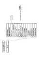
図示の通り、情報処理装置1は、コンピュータ機能部として情報処理コントローラ11を備える。情報処理コントローラ11は、メインプロセッサ21−1、サブプロセッサ23−1、23−2、23−3、DMAC(ダイレクトメモリアクセスコントローラ)25−1、及びDC(ディスクコントローラ)27−1を備えている。情報処理コントローラ11は、ワンチップIC(集積回路)として構成することが望ましい。 As illustrated, the
メインプロセッサ21−1は、サブプロセッサ23−1、23−2、23−3によるプログラム実行(データ処理)のスケジュール管理と、情報処理コントローラ11(情報処理装置1)の全般的な管理とを行なう。但し、メインプロセッサ21−1内で管理を行なうためのプログラム以外のプログラムが動作するように構成することもできる。この場合、メインプロセッサ21−1はサブプロセッサとしても機能することになる。メインプロセッサ21−1は、LS(ローカル・ストレージ)22−1を備えている。 The main processor 21-1 performs schedule management of program execution (data processing) by the sub processors 23-1, 23-2, and 23-3, and general management of the information processing controller 11 (information processing apparatus 1). . However, a program other than the program for performing management in the main processor 21-1 can be configured to operate. In this case, the main processor 21-1 also functions as a sub processor. The main processor 21-1 includes an LS (local storage) 22-1.
1台の情報処理装置に備わるサブプロセッサは1つでもよいが、望ましくは複数とする。図示の例では、複数の場合である。各サブプロセッサ23−1、23−2、23−3は、メインプロセッサ21−1の制御下で、並列的且つ独立にプログラムを実行し、データを処理する。さらに、場合によってメインプロセッサ21−1内のプログラムがサブプロセッサ23−1、23−2、23−3内のプログラムと連携して動作することもできる。各サブプロセッサ23−1、23−2、23−3も、それぞれLS(ローカルストレージ)24−1、24−2、24−3を備えている。 One information processor may have one sub-processor, but preferably a plurality of sub-processors. In the illustrated example, there are a plurality of cases. Each sub-processor 23-1, 23-2, 23-3 executes a program in parallel and independently under the control of the main processor 21-1, and processes data. Further, in some cases, the program in the main processor 21-1 can operate in cooperation with the programs in the sub processors 23-1, 23-2, and 23-3. The sub-processors 23-1, 23-2, and 23-3 also include LS (local storage) 24-1, 24-2, and 24-3, respectively.
DMAC(直接メモリアクセスコントローラ)25−1は、情報処理コントローラ11に接続されたDRAM(ダイナミックRAM)などからなるメインメモリ26−1に格納されているプログラム及びデータにプロセッサの介在なしにアクセスするものである。また、DC(ディスクコントローラ)27−1は、情報処理コントローラ11に接続された外部記録部28−1、28−2へのアクセス動作を制御する。 The DMAC (direct memory access controller) 25-1 accesses a program and data stored in a main memory 26-1 including a DRAM (dynamic RAM) connected to the
外部記録部28−1、28−2は、固定ディスク(ハードディスク)、あるいはリムーバブルディスクのいずれの形態でもよい。また、リムーバブルディスクとして、MO(磁気ディスク)、CD±RW、DVD±RWなどの光ディスク、メモリディスク、SRAM(スタティックRAM)、ROMなど各種の記録メディアを用いることができる。DC27−1は、ディスクコントローラと称するが、要するに外部記録部コントローラである。図1に示すように、外部記録部28を複数接続できるように、情報処理コントローラ11を構成することができる。 The external recording units 28-1 and 28-2 may be either a fixed disk (hard disk) or a removable disk. As the removable disk, various recording media such as MO (magnetic disk), CD ± RW, DVD ± RW and other optical disks, memory disks, SRAM (static RAM), ROM and the like can be used. The DC 27-1 is called a disk controller, but in short, is an external recording unit controller. As shown in FIG. 1, the
メインプロセッサ21−1、各サブプロセッサ23−1、23−2、23−3、DMAC25−1、及びDC27−1は、バス29−1によって相互接続されている。 The main processor 21-1, the sub processors 23-1, 23-2, 23-3, the DMAC 25-1, and the DC 27-1 are interconnected by a bus 29-1.
情報処理コントローラ11には、当該情報処理コントローラ11を搭載する情報処理装置1をネットワーク全体を通して一意に識別できる識別子が、情報処理装置IDとして割り当てられている。また、メインプロセッサ21−1及び各サブプロセッサ23−1、23−2、23−3に対しても同様に、それぞれを特定できる識別子が、メインプロセッサID及びサブプロセッサIDとして割り当てられる。 An identifier capable of uniquely identifying the
他の情報処理装置2、3、4も同様に構成されるので、ここでは説明を省略する。ここで、親番号が同一であるユニットは枝番号が異なっていても、特に断りがない限り同じ働きをするものとする。また、以下の説明において枝番号が省略されている場合には、枝番号の違いによる差異を生じないものとする。 Since the other
A−2.各サブプロセッサからメインメモリへのアクセス
上述したように、1つの情報処理コントローラ内の各サブプロセッサ23は、独立にプログラムを実行し、データを処理するが、異なるサブプロセッサがメインメモリ26内の同一領域に対して同時に読み出し又は書き込みを行なった場合には、データの不整合を生じ得る。そこで、サブプロセッサ23からメインメモリ26へのアクセスは、以下のような手順によって行なう。A-2. Access to Main Memory from Each Sub-Processor As described above, each sub-processor 23 in one information processing controller independently executes a program and processes data, but different sub-processors are the same in main memory 26. If data is read from or written to the area at the same time, data mismatch may occur. Therefore, the access from the sub processor 23 to the main memory 26 is performed according to the following procedure.
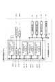
図2(A)には、メインメモリ26内のロケーションを示している。同図に示すように、メインメモリ26は複数のアドレスを指定できるメモリロケーションによって構成され、各メモリロケーションに対してデータの状態を示す情報を格納するための追加セグメントが割り振られる。追加セグメントは、F/Eビット、サブプロセッサID及びLSアドレス(ローカル・ストレージアドレス)を含むものとされる。また、各メモリロケーションには、後述のアクセス・キーも割り振られる。F/Eビットは、以下のように定義される。 FIG. 2A shows a location in the main memory 26. As shown in the figure, the main memory 26 is composed of memory locations that can specify a plurality of addresses, and an additional segment for storing information indicating the state of data is allocated to each memory location. The additional segment includes an F / E bit, a sub processor ID, and an LS address (local storage address). Each memory location is also assigned an access key to be described later. The F / E bit is defined as follows.
F/Eビット=0は、サブプロセッサ23によって読み出されている処理中のデータ、又は空き状態であるため最新データではない無効データであり、読み出し不可であることを示す。また、F/Eビット=0は、当該メモリ・ロケーションにデータ書き込み可能であることを示し、書き込み後に1に設定される。 The F / E bit = 0 indicates that the data being processed being read by the sub-processor 23 or invalid data that is not the latest data because it is empty, and cannot be read. The F / E bit = 0 indicates that data can be written to the memory location, and is set to 1 after writing.
F/Eビット=1は、当該メモリロケーションのデータがサブプロセッサ23によって読み出されておらず、未処理の最新データであることを示す。当該メモリ・ロケーションのデータは読み出し可能であり、サブプロセッサ23によって読み出された後に0に設定される。また、F/Eビット=1は、当該メモリ・ロケーションがデータ書き込み不可であることを示す。 The F / E bit = 1 indicates that the data at the memory location has not been read by the sub-processor 23 and is the latest unprocessed data. The data in the memory location can be read and set to 0 after being read by the sub-processor 23. Further, the F / E bit = 1 indicates that the memory location cannot write data.
さらに、上記F/Eビット=0(読み出し不可/書き込み可)の状態において、当該メモリロケーションについて読み出し予約を設定することは可能である。F/Eビット=0のメモリロケーションに対して読み出し予約を行なう場合には、サブプロセッサ23は、読み出し予約を行なうメモリロケーションの追加セグメントに、読み出し予約情報として当該サブプロセッサ23のサブプロセッサID及びLSアドレスを書き込む。 Furthermore, it is possible to set a read reservation for the memory location in the state where the F / E bit = 0 (read disabled / write enabled). When a read reservation is made for a memory location with the F / E bit = 0, the sub-processor 23 adds the sub-processor ID and LS of the sub-processor 23 as read reservation information to an additional segment of the memory location where the read reservation is made. Write the address.
その後、データ書き込み側のサブプロセッサ23により、読み出し予約されたメモリ・ロケーションにデータが書き込まれ、F/Eビット=1(読み出し可/書き込み不可)に設定されたとき、あらかじめ読み出し予約情報として追加セグメントに書き込まれたサブプロセッサID及びLSアドレスに読み出される。 Thereafter, when data is written to the memory location reserved for reading by the sub-processor 23 on the data writing side and the F / E bit is set to 1 (readable / not writable), an additional segment is set in advance as read reservation information. Is read into the sub processor ID and LS address written in.
複数のサブプロセッサによってデータを多段階に処理する必要がある場合、このように各メモリロケーションのデータの読み出し/書き込みを制御することにより、前段階の処理を行なうサブプロセッサ23が処理済みのデータをメインメモリ26上の所定のアドレスに書き込んだ後に即座に、後段階の処理を行なう別のサブプロセッサ23が前処理後のデータを読み出すことが可能となる。 When it is necessary to process data in multiple stages by a plurality of sub-processors, the sub-processor 23 that performs the process in the previous stage controls the processed data by controlling the reading / writing of data in each memory location in this way. Immediately after writing to a predetermined address on the main memory 26, it becomes possible for another sub-processor 23, which performs the subsequent processing, to read the pre-processed data.
また、図2(B)には、各サブプロセッサ23内のLS24におけるメモリロケーションを示している。同図に示すように、各サブプロセッサ23内のLS24も、複数のアドレスを指定できるメモリロケーションによって構成される。各メモリロケーションに対しては、同様に追加セグメントが割り振られる。追加セグメントは、ビジービットを含むものとされる。 FIG. 2B shows the memory location in the LS 24 in each sub processor 23. As shown in the figure, the LS 24 in each sub-processor 23 is also composed of memory locations that can specify a plurality of addresses. An additional segment is similarly allocated for each memory location. The additional segment includes a busy bit.
サブプロセッサ23がメインメモリ26内のデータを自身のLS24のメモリロケーションに読み出すときには、対応するビジービットを1に設定して予約する。ビジービットが1であるメモリロケーションには、他のデータは格納することができない。LS24のメモリロケーションに読み出し後、ビジービットは0になり、任意の目的に使用できるようになる。 When the sub-processor 23 reads the data in the main memory 26 to the memory location of its own LS 24, it reserves by setting the corresponding busy bit to 1. No other data can be stored in the memory location where the busy bit is 1. After reading to the memory location of the LS 24, the busy bit becomes 0 and can be used for any purpose.
図2(A)に示すように、さらに、各情報処理コントローラと接続されたメインメモリ26には、メインメモリ26内の領域を画定する複数のサンドボックスが含まれる。メインメモリ26は、複数のメモリロケーションから構成されるが、サンドボックスは、これらのメモリロケーションの集合である。各サンドボックスは、サブプロセッサ23毎に割り当てられ、該当するサブプロセッサが排他的に使用することができる。すなわち、各々のサブプロセッサ23は、自身に割り当てられたサンドボックスを使用できるが、この領域を超えてデータのアクセスを行なうことはできない。 As shown in FIG. 2A, the main memory 26 connected to each information processing controller further includes a plurality of sandboxes that define areas in the main memory 26. The main memory 26 is composed of a plurality of memory locations, and the sandbox is a set of these memory locations. Each sandbox is assigned to each sub-processor 23 and can be used exclusively by the corresponding sub-processor. That is, each sub-processor 23 can use the sandbox assigned to itself, but cannot access data beyond this area.
さらに、メインメモリ26の排他的な制御を実現するために、図2(C)に示すようなキー管理テーブルが用いられる。キー管理テーブルは、情報処理コントローラ内のSRAMのような比較的高速のメモリに格納され、DMAC25と関連付けられる。キー管理テーブル内の各エントリには、サブプロセッサID、サブプロセッサキー及びキーマスクが含まれる。 Further, in order to realize exclusive control of the main memory 26, a key management table as shown in FIG. The key management table is stored in a relatively high-speed memory such as SRAM in the information processing controller, and is associated with the DMAC 25. Each entry in the key management table includes a sub processor ID, a sub processor key, and a key mask.
サブプロセッサ23がメインメモリ26を使用する際のプロセスは、以下の通りである。まず、サブプロセッサ23はDMAC25に、読み出し又は書き込みのコマンドを出力する。このコマンドには、自身のサブプロセッサIDと、使用要求先であるメインメモリ26のアドレスが含まれる。 The process when the sub processor 23 uses the main memory 26 is as follows. First, the sub processor 23 outputs a read or write command to the DMAC 25. This command includes its own sub-processor ID and the address of the main memory 26 that is the use request destination.
DMAC25は、このコマンドを実行する前にキー管理テーブルを参照し、使用要求元のサブプロセッサのサブプロセッサキーを調べる。次に、DMAC25は、調べた使用要求元のサブプロセッサキーと、使用要求先であるメインメモリ26内の図2(A)に示したメモリロケーションに割り振られたアクセスキーとを比較して、2つのキーが一致した場合にのみ、上記のコマンドを実行する。 Before executing this command, the DMAC 25 refers to the key management table and checks the sub processor key of the sub processor of the use request source. Next, the DMAC 25 compares the checked sub-processor key of the use request source with the access key allocated to the memory location shown in FIG. Execute the above command only when two keys match.
図2(C)に示したキー管理テーブル上のキーマスクは、その任意のビットが1になることによって、そのキーマスクに関連付けられたサブプロセッサキーの対応するビットが0又は1になることができる。 In the key mask on the key management table shown in FIG. 2C, when the arbitrary bit becomes 1, the corresponding bit of the sub-processor key associated with the key mask may become 0 or 1. it can.
例えば、サブプロセッサキーが1010であるとする。通常、このサブプロセッサキーによって1010のアクセスキーを持つサンドボックスへのアクセスだけが可能になる。しかし、このサブプロセッサキーと関連付けられたキーマスクが0001に設定されている場合には、キーマスクのビットが1に設定された桁のみにつき、サブプロセッサキーとアクセスキーとの一致判定がマスクされ、このサブプロセッサキー1010によってアクセスキーが1010又は1011のいずれかであるアクセスキーを持つサンドボックスへのアクセスが可能となる。 For example, assume that the sub-processor key is 1010. Normally, this sub-processor key only allows access to a sandbox with 1010 access keys. However, if the key mask associated with this sub-processor key is set to 0001, the match determination between the sub-processor key and the access key is masked only for the digit whose key mask bit is set to 1. The sub processor key 1010 enables access to a sandbox having an access key whose access key is either 1010 or 1011.
以上のようにして、メインメモリ26のサンドボックスの排他性が実現される。すなわち、1つの情報処理コントローラ内に配置された複数のサブプロセッサによってデータを多段階に処理する必要がある場合、前段階の処理を行なうサブプロセッサと、後段階の処理を行なうサブプロセッサのみが、メインメモリ26の所定アドレスにアクセスできるようになり、データを保護することができる。 As described above, the sandbox exclusivity of the main memory 26 is realized. That is, when it is necessary to process data in multiple stages by a plurality of sub-processors arranged in one information processing controller, only the sub-processor that performs the previous stage process and the sub-processor that performs the subsequent stage process, It becomes possible to access a predetermined address of the main memory 26, and data can be protected.
このようなメモリの排他制御は、例えば以下のように使用することができる。まず、情報処理装置の起動直後においては、キーマスクの値はすべてゼロである。メインプロセッサ内のプログラムが実行され、サブプロセッサ内のプログラムと連携動作するものとする。第1のサブプロセッサにより出力された処理結果データを一旦メインメモリに格納し、第2のサブプロセッサに入力したいときには、該当するメインメモリ領域は、当然どちらのサブプロセッサからもアクセス可能である必要がある。このような場合に、メインプロセッサ内のプログラムは、キーマスクの値を適切に変更し、複数のサブプロセッサからアクセスできるメインメモリ領域を設けることにより、サブプロセッサによる多段階的の処理を可能にする。 Such exclusive memory control can be used as follows, for example. First, immediately after the information processing apparatus is activated, the key mask values are all zero. It is assumed that a program in the main processor is executed and operates in cooperation with a program in the sub processor. When the processing result data output by the first sub-processor is temporarily stored in the main memory and desired to be input to the second sub-processor, the corresponding main memory area must naturally be accessible from either sub-processor. is there. In such a case, the program in the main processor appropriately changes the value of the key mask and provides a main memory area that can be accessed from a plurality of sub processors, thereby enabling multi-stage processing by the sub processors. .
より具体的には、他の情報処理装置からのデータ→第1のサブプロセッサによる処理→第1のメインメモリ領域→第2のサブプロセッサによる処理→第2のメインメモリ領域、という手順で多段階処理が行なわれるときには、以下のような設定のままでは、第2のサブプロセッサは第1のメインメモリ領域にアクセスすることができない。 More specifically, it is a multi-step process in the order of data from another information processing apparatus → processing by the first sub processor → first main memory area → processing by the second sub processor → second main memory area. When processing is performed, the second sub-processor cannot access the first main memory area with the following settings.
第1のサブプロセッサのサブプロセッサ・キー:0100、
第1のメインメモリ領域のアクセス・キー :0100、
第2のサブプロセッサのサブプロセッサ・キー:0101、
第2のメインメモリ領域のアクセス・キー :0101Sub-processor key of the first sub-processor: 0100
First main memory area access key: 0100,
Sub-processor key of the second sub-processor: 0101,
Second main memory area access key: 0101
そこで、第2のサブプロセッサのキーマスクを0001にすることにより、第2のサブプロセッサによる第1のメインメモリ領域へのアクセスを可能にすることができる。 Therefore, by setting the key mask of the second sub processor to 0001, it is possible to allow the second sub processor to access the first main memory area.
A−3.ソフトウェアセルの生成及び構成
図1のネットワークシステムでは、情報処理装置1、2、3、4間での分散処理のために、情報処理装置1、2、3、4間でソフトウェアセルが伝送される。すなわち、ある情報処理装置内の情報処理コントローラに含まれるメインプロセッサ21は、コマンド、プログラム及びデータを含むソフトウェアセルを生成し、ネットワーク9を介して他の情報処理装置に送信することによって、処理を分散することができる。A-3. 1.Generation and configuration of software cell In the network system of FIG. 1, a software cell is transmitted between
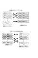
図3には、ソフトウェアセルの構成の一例を示している。図示のソフトウェアセルは、送信元ID、送信先ID、応答先ID、セルインターフェース、DMAコマンド、プログラム、及びデータによって構成される。 FIG. 3 shows an example of the configuration of the software cell. The illustrated software cell includes a transmission source ID, a transmission destination ID, a response destination ID, a cell interface, a DMA command, a program, and data.
送信元IDには、ソフトウェアセルの送信元である情報処理装置のネットワークアドレス及び当該情報処理装置内の情報処理コントローラの情報処理装置ID、さらに、当該情報処理装置内の情報処理コントローラが備えるメインプロセッサ21及び各サブプロセッサ23の識別子(メインプロセッサID及びサブプロセッサID)が含まれる。 The transmission source ID includes the network address of the information processing apparatus that is the transmission source of the software cell, the information processing apparatus ID of the information processing controller in the information processing apparatus, and the main processor included in the information processing controller in the information processing apparatus 21 and the identifiers (main processor ID and sub processor ID) of each sub processor 23 are included.
送信先ID及び応答先IDには、ソフトウェアセルの送信先である情報処理装置、及びソフトウェアセルの実行結果の応答先である情報処理装置についての同じ情報がそれぞれ含まれる。 The transmission destination ID and the response destination ID respectively include the same information about the information processing apparatus that is the transmission destination of the software cell and the information processing apparatus that is the response destination of the execution result of the software cell.
セルインターフェースは、ソフトウェアセルの利用に必要な情報であり、グローバルID、必要なサブプロセッサの情報、サンドボックスサイズ、及び前回のソフトウェアセルIDで構成される。 The cell interface is information necessary for using the software cell, and includes a global ID, necessary sub-processor information, a sandbox size, and a previous software cell ID.
グローバルIDは、ネットワーク全体を通して当該のソフトウェアセルを一意的に識別できるものであり、送信元IDと、ソフトウェアセルの作成又は送信の日時(日付及び時刻)に基づいて作成される。 The global ID uniquely identifies the software cell throughout the network, and is created based on the transmission source ID and the date and time (date and time) of creation or transmission of the software cell.
必要なサブプロセッサの情報は、当該ソフトウェアセルの実行に必要なサブプロセッサの数が設定される。サンドボックスサイズは、当該ソフトウェアセルの実行に必要なメインメモリ26内及びサブプロセッサ23のLS24内のメモリ量が設定される。 In the necessary sub-processor information, the number of sub-processors necessary for executing the software cell is set. As the sandbox size, the amount of memory in the main memory 26 and the LS 24 of the sub processor 23 necessary for executing the software cell is set.
前回のソフトウェアセルIDは、ストリーミングデータなどのシーケンシャルな実行を要求する1グループのソフトウェアセル内の、前回のソフトウェアセルの識別子である。 The previous software cell ID is an identifier of the previous software cell in a group of software cells that request sequential execution of streaming data or the like.
ソフトウェアセルの実行セクションは、DMAコマンド、プログラム及びデータで構成される。DMAコマンドには、プログラムの起動に必要な一連のDMAコマンドが含まれ、プログラムには、サブプロセッサ23によって実行されるサブプロセッサプログラムが含まれる。ここでのデータは、このサブプロセッサプログラムを含むプログラムによって処理されるデータである。 The execution section of the software cell is composed of DMA commands, programs, and data. The DMA command includes a series of DMA commands necessary for starting the program, and the program includes a sub processor program executed by the sub processor 23. The data here is data processed by a program including the sub processor program.
さらに、DMAコマンドには、ロードコマンド、キックコマンド、機能プログラム実行コマンド、ステータス要求コマンド、及びステータス返信コマンドが含まれる。 Further, the DMA command includes a load command, a kick command, a function program execution command, a status request command, and a status return command.
ロードコマンドは、メインメモリ26内の情報をサブプロセッサ23内のLS24にロードするコマンドであり、ロードコマンド自体の他に、メインメモリアドレス、サブプロセッサID及びLSアドレスを含む。メインメモリアドレスは、情報のロード元であるメインメモリ26内の所定領域のアドレスを示す。サブプロセッサID及びLSアドレスは、情報のロード先であるサブプロセッサ23の識別子及びLS24のアドレスを示す。 The load command is a command for loading information in the main memory 26 into the LS 24 in the sub processor 23, and includes a main memory address, a sub processor ID, and an LS address in addition to the load command itself. The main memory address indicates an address of a predetermined area in the main memory 26 from which information is loaded. The sub processor ID and the LS address indicate the identifier of the sub processor 23 to which the information is loaded and the address of the LS 24.
キックコマンドは、プログラムの実行を開始するコマンドであり、キックコマンド自体の他に、サブプロセッサID及びプログラムカウンタを含む。サブプロセッサIDは、キック対象のサブプロセッサ23を識別し、プログラムカウンタは、プログラム実行用プログラムカウンタのためのアドレスを与える。 The kick command is a command for starting execution of the program, and includes a sub processor ID and a program counter in addition to the kick command itself. The sub processor ID identifies the sub processor 23 to be kicked, and the program counter gives an address for the program execution program counter.
機能プログラム実行コマンドは、ある情報処理装置が他の情報処理装置に対して、機能プログラムの実行を要求するコマンドである(後述)。機能プログラム実行コマンドを受信した情報処理装置内の情報処理コントローラは、機能プログラムID(後述)によって、起動すべき機能プログラムを識別する。 The function program execution command is a command for requesting execution of a function program from another information processing apparatus to another information processing apparatus (described later). The information processing controller in the information processing apparatus that has received the function program execution command identifies a function program to be activated by a function program ID (described later).
ステータス要求コマンドは、送信先IDで示される情報処理装置の現在の動作状態(状況)に関する装置情報を、応答先IDで示される情報処理装置宛に送信要求するコマンドである。機能プログラムについては後述するが、図6に示す情報処理コントローラのメインメモリ26が記憶するソフトウェアの構成図において機能プログラムにカテゴライズされるプログラムである。機能プログラムは、メインメモリ26にロードされ、メインプロセッサ21により実行される。 The status request command is a command for requesting transmission of device information related to the current operation state (situation) of the information processing device indicated by the transmission destination ID to the information processing device indicated by the response destination ID. Although the function program will be described later, it is a program categorized into the function program in the software configuration diagram stored in the main memory 26 of the information processing controller shown in FIG. The function program is loaded into the main memory 26 and executed by the main processor 21.
ステータス返信コマンドは、上記のステータス要求コマンドを受信した情報処理装置が、自身の装置情報を当該ステータス要求コマンドに含まれる応答先IDで示される情報処理装置に応答するコマンドである。ステータス返信コマンドは、実行セクションのデータ領域に装置情報を格納する。 The status reply command is a command in which the information processing apparatus that has received the status request command responds to the information processing apparatus indicated by the response destination ID included in the status request command with its own apparatus information. The status reply command stores device information in the data area of the execution section.
図4には、DMAコマンドがステータス返信コマンドである場合におけるソフトウェアセルのデータ領域の構造を示している。 FIG. 4 shows the structure of the data area of the software cell when the DMA command is a status return command.
情報処理装置IDは、情報処理コントローラを備える情報処理装置を識別するための識別子であり、ステータス返信コマンドを送信する情報処理装置のIDを示す。情報処理装置IDは、電源投入時に、その情報処理装置内の情報処理コントローラに含まれるメインプロセッサ21によって、電源投入時の日時、情報処理装置のネットワークアドレス及び情報処理装置内の情報処理コントローラに含まれるサブプロセッサ23の数などに基づいて生成される。 The information processing device ID is an identifier for identifying the information processing device including the information processing controller, and indicates the ID of the information processing device that transmits the status reply command. The information processing apparatus ID is included in the information processing controller in the information processing apparatus by the main processor 21 included in the information processing controller in the information processing apparatus when the power is turned on. It is generated based on the number of sub processors 23 to be processed.
情報処理装置種別IDには、当該情報処理装置の特徴を表す値が含まれる。ここで言う情報処理装置の特徴とは、例えば、ハードディスクレコーダ(後述)、PDA(Personal Digital Assistants)、ポータブルCD(Compact Disc)プレーヤなどである。また、情報処理装置種別IDは、映像音声記録、映像音声再生など、情報処理装置が持つ機能を表すものであってもよい、情報処理装置の特徴や機能を表す値はあらかじめ決められているものとし、情報処理装置種別IDを呼び出すことにより当該情報処理装置の特徴や機能を把握することが可能である。 The information processing device type ID includes a value representing the characteristics of the information processing device. The features of the information processing apparatus mentioned here include, for example, a hard disk recorder (described later), a PDA (Personal Digital Assistants), a portable CD (Compact Disc) player, and the like. The information processing device type ID may represent a function of the information processing device such as video / audio recording or video / audio reproduction. Values representing the characteristics and functions of the information processing device are predetermined. By calling the information processing device type ID, it is possible to grasp the characteristics and functions of the information processing device.
MS(マスター/スレーブ)ステータスは、後述するように情報処理装置がマスター装置又はスレーブ装置のいずれで動作しているかを表すもので、これが0に設定されている場合にはマスター装置として動作していることを示し、1に設定されている場合にはスレーブ装置として動作していることを示す。 The MS (master / slave) status indicates whether the information processing apparatus is operating as a master apparatus or a slave apparatus, as will be described later. When this is set to 0, it operates as a master apparatus. If it is set to 1, it indicates that it is operating as a slave device.
メインプロセッサ動作周波数は、情報処理コントローラ内のメインプロセッサ21の動作周波数を表す。メインプロセッサ使用率は、メインプロセッサ21で現在動作しているすべてのプログラムについての、メインプロセッサ21での使用率を表す。メインプロセッサ使用率は、対象メインプロセッサの全処理能力に対する使用中の処理能力の比率を表した値で、例えばプロセッサ処理能力評価のための単位であるMIPS[Million Instructions Per Second]を単位として算出され、又は単位時間当りのプロセッサ使用時間に基づいて算出される。後述のサブプロセッサ使用率についても同様である。 The main processor operating frequency represents the operating frequency of the main processor 21 in the information processing controller. The main processor usage rate represents the usage rate in the main processor 21 for all programs currently running on the main processor 21. The main processor usage rate is a value representing the ratio of the processing capacity in use to the total processing capacity of the target main processor. For example, MIPS [Million Instructions Per Second], which is a unit for evaluating the processor processing capacity, is calculated as a unit. Or based on the processor usage time per unit time. The same applies to the sub-processor usage rate described later.
サブプロセッサ数は、当該の情報処理コントローラが備えるサブプロセッサ23の数を表す。サブプロセッサIDは、当該の情報処理コントローラ内の各サブプロセッサ23を識別するための識別子である。 The number of sub-processors represents the number of sub-processors 23 included in the information processing controller. The sub processor ID is an identifier for identifying each sub processor 23 in the information processing controller.
サブプロセッサステータスは、各サブプロセッサ23の状態を表すものであり、unused、reserved,busyなどの状態がある。unusedは、当該サブプロセッサが現在使用されてなく、使用の予約もされていないことを示す。reservedは、現在は使用されていないが、予約されている状態を示す。busyは、現在使用中であることを示す。 The sub processor status represents the state of each sub processor 23, and there are states such as “unused”, “reserved”, and “busy”. “unused” indicates that the sub-processor is not currently used and is not reserved for use. “reserved” indicates a reserved state that is not currently used. Busy indicates that it is currently in use.
サブプロセッサ使用率は、当該のサブプロセッサで現在実行している、又は当該のサブプロセッサに実行が予約されているプログラムについての、当該サブプロセッサでの使用率を表す。すなわち、サブプロセッサ使用率は、サブプロセッサステータスがbusyである場合には、現在の使用率を示し、サブプロセッサステータスがreservedである場合には、後に使用される予定の推定使用率を示す。 The sub-processor usage rate represents the usage rate in the sub-processor for a program that is currently being executed in the sub-processor or that is reserved for execution in the sub-processor. That is, the sub processor usage rate indicates the current usage rate when the sub processor status is busy, and indicates the estimated usage rate that is to be used later when the sub processor status is reserved.
サブプロセッサID、サブプロセッサステータス及びサブプロセッサ使用率は、1つのサブプロセッサ23に対して一組設定され、1つの情報処理コントローラ内のサブプロセッサ23に対応する組数が設定される。 One set of sub processor ID, sub processor status, and sub processor usage rate is set for one sub processor 23, and the number of sets corresponding to the sub processor 23 in one information processing controller is set.
メインメモリ総容量及びメインメモリ使用量は、それぞれ、当該の情報処理コントローラに接続されているメインメモリ26の総容量及び現在使用中の容量を表す。 The total main memory capacity and the main memory usage represent the total capacity and the currently used capacity of the main memory 26 connected to the information processing controller, respectively.
外部記録部数は、当該の情報処理コントローラに接続されている外部記録部28の数を表す。外部記録部IDは、当該の情報処理コントローラに接続されている外部記録部28を一意的に識別する情報である。外部記録部種別IDは、当該の外部記録部の種類(例えば、ハードディスク、CD±RW、DVD±RW、メモリディスク、SRAM、ROMなど)を表す。 The number of external recording units represents the number of external recording units 28 connected to the information processing controller. The external recording unit ID is information that uniquely identifies the external recording unit 28 connected to the information processing controller. The external recording unit type ID represents the type of the external recording unit (for example, hard disk, CD ± RW, DVD ± RW, memory disk, SRAM, ROM, etc.).
外部記録部総容量及び外部記録部使用量は、それぞれ外部記録部IDによって識別される外部記録部28の総容量及び現在使用中の容量を表す。 The external recording unit total capacity and the external recording unit usage amount represent the total capacity and the currently used capacity of the external recording unit 28 identified by the external recording unit ID, respectively.
外部記録部ID、外部記録部種別ID、外部記録部総容量及び外部記録部使用量は、1つの外部記録部28に対して1組設定されるものであり、当該情報処理コントローラに接続されている外部記録部28の数の組数だけ設定される。すなわち、1つの情報処理コントローラに複数の外部記録部が接続されている場合、それぞれの外部記録部には異なる外部記録部IDが割り当てられ、外部記録部種別ID、外部記録部総容量及び外部記録部使用量も別々に管理される。 The external recording unit ID, the external recording unit type ID, the external recording unit total capacity, and the external recording unit usage amount are set for one external recording unit 28 and connected to the information processing controller. The number of sets is equal to the number of external recording units 28. That is, when a plurality of external recording units are connected to one information processing controller, different external recording unit IDs are assigned to the respective external recording units, the external recording unit type ID, the external recording unit total capacity, and the external recording unit. Department usage is also managed separately.
A−4ソフトウェアセルの実行
ある情報処理装置内の情報処理コントローラに含まれるメインプロセッサ21は、上述したような構成のソフトウェアセルを生成し、ネットワーク9を介して他の情報処理装置及び当該装置内の情報処理コントローラに送信する。送信元の情報処理装置、送信先の情報処理装置、応答先の情報処理装置、及び各装置内の情報処理コントローラは、それぞれ、上記の送信元ID、送信先ID及び応答先IDによって識別される。A-4 The main processor 21 included in the information processing controller in the information processing apparatus thatexecutes the software cell generates the software cell having the above-described configuration, and the other information processing apparatus and the inside of the apparatus via the network 9 To the information processing controller. The transmission source information processing device, the transmission destination information processing device, the response destination information processing device, and the information processing controller in each device are identified by the transmission source ID, the transmission destination ID, and the response destination ID, respectively. .
ソフトウェアセルを受信した情報処理装置内の情報処理コントローラに含まれるメインプロセッサ21は、そのソフトウェアセルをメインメモリ26に格納する。さらに、送信先のメインプロセッサ21は、ソフトウェアセルを読み出し、それに含まれるDMAコマンドを処理する。 The main processor 21 included in the information processing controller in the information processing apparatus that has received the software cell stores the software cell in the main memory 26. Furthermore, the transmission destination main processor 21 reads the software cell and processes the DMA command included therein.
具体的には、送信先のメインプロセッサ21は、まず、ロードコマンドを実行する。これによって、ロードコマンドで指示されたメインメモリアドレスから、ロードコマンドに含まれるサブプロセッサID及びLSアドレスで特定されるサブプロセッサ内のLS24の所定領域に情報がロードされる。ここでロードされる情報は、受信したソフトウェアセルに含まれるサブプロセッサプログラム又はデータ、あるいはその他の指示されたデータである。 Specifically, the transmission destination main processor 21 first executes a load command. As a result, information is loaded from the main memory address instructed by the load command into a predetermined area of the LS 24 in the sub processor identified by the sub processor ID and LS address included in the load command. The information loaded here is a sub-processor program or data included in the received software cell, or other designated data.
次に、メインプロセッサ21は、キックコマンドを、これに含まれるサブプロセッサIDで指示されたサブプロセッサに、同様にキックコマンドに含まれるプログラムカウンタとともに出力する。 Next, the main processor 21 outputs the kick command together with the program counter included in the kick command to the sub processor indicated by the sub processor ID included therein.
指示されたサブプロセッサは、そのキックコマンド及びプログラムカウンタに従って、サブプロセッサプログラムを実行する。そして、実行結果をメインメモリ26に格納した後、実行を完了したことをメインプロセッサ21に通知する。 The instructed sub processor executes the sub processor program according to the kick command and the program counter. After the execution result is stored in the main memory 26, the main processor 21 is notified that the execution has been completed.
なお、送信先の情報処理装置内の情報処理コントローラにおいてソフトウェアセルを実行するプロセッサはサブプロセッサ23に限定されるものではなく、メインプロセッサ21がソフトウェアセルに含まれる機能プログラムなどのメインメモリ用プログラムを実行するように指定することも可能である。 Note that the processor that executes the software cell in the information processing controller in the information processing apparatus of the transmission destination is not limited to the sub-processor 23, but the main processor 21 executes a program for main memory such as a function program included in the software cell. It can also be specified to execute.
この場合には、送信元の情報処理装置は、送信先の情報処理装置宛に、サブプロセッサプログラムの代わりに、メインメモリ用プログラム及びそのメインメモリ用プログラムによって処理されるデータを含み、DMAコマンドがロードコマンドであるソフトウェアセルを送信し、メインメモリ26にメインメモリ用プログラム及びそれによって処理されるデータを記憶させる。 In this case, the transmission source information processing apparatus includes a main memory program and data processed by the main memory program instead of the sub processor program, and the DMA command is sent to the transmission destination information processing apparatus. A software cell as a load command is transmitted, and the main memory 26 stores the main memory program and data processed thereby.
次に、送信元の情報処理装置は、送信先の情報処理装置宛てに、送信先の情報処理装置内の情報処理コントローラについてのメインプロセッサID、メインメモリ・アドレス、メインメモリ用プログラムを識別するための後述の機能プログラムIDなどの識別子、及びプログラムカウンタを含み、DMAコマンドがキックコマンド又は機能プログラム実行コマンドであるソフトウェアセルを送信し、メインプロセッサ21に当該メインメモリ用プログラムを実行させる。 Next, the transmission source information processing apparatus identifies the main processor ID, the main memory address, and the main memory program for the information processing controller in the transmission destination information processing apparatus to the transmission destination information processing apparatus. And a software cell in which the DMA command is a kick command or a function program execution command, and causes the main processor 21 to execute the main memory program.
以上のように、本実施形態に係るネットワークシステムでは、送信元の情報処理装置は、サブプロセッサプログラム又はメインメモリ用プログラムをソフトウェアセルによって送信先の情報処理装置に送信するとともに、当該サブプロセッサプログラムを送信先の情報処理装置内の情報処理コントローラに含まれるサブプロセッサ23にロードさせ、当該サブプロセッサプログラム又は当該メインメモリ用プログラムを送信先の情報処理装置に実行させることができる。 As described above, in the network system according to the present embodiment, the transmission source information processing apparatus transmits the sub processor program or the main memory program to the transmission destination information processing apparatus using software cells, and the sub processor program is The sub processor 23 included in the information processing controller in the information processing apparatus of the transmission destination can be loaded, and the information processing apparatus of the transmission destination can execute the sub processor program or the main memory program.
送信先の情報処理装置内の情報処理コントローラでは、受信したソフトウェアセルに含まれるプログラムがサブプロセッサプログラムである場合には、当該サブプロセッサプログラムを指定されたサブプロセッサにロードさせる。そして、ソフトウェアセルに含まれるサブプロセッサプログラム又はメインメモリ用プログラムを実行させる。 When the program included in the received software cell is a sub processor program, the information processing controller in the transmission destination information processing apparatus loads the sub processor program to the designated sub processor. Then, the sub processor program or the main memory program included in the software cell is executed.
したがって、ユーザが送信先の情報処理装置を操作しなくても、当該サブプロセッサプログラム又は当該メインメモリ用プログラムを送信先の情報処理装置内の情報処理コントローラにおいて自動的に実行させることができる。 Therefore, even if the user does not operate the transmission destination information processing apparatus, the sub processor program or the main memory program can be automatically executed by the information processing controller in the transmission destination information processing apparatus.
このようにして情報処理装置は、自装置内の情報処理コントローラがサブプロセッサプログラム又は機能プログラムなどのメインメモリ用プログラムを備えていない場合には、ネットワークに接続された他の情報処理装置からそれらを取得することができる。さらに、各サブプロセッサ間ではDMA方式によりデータ転送を行ない、また上述したサンドボックスを使用することにより、1つの情報処理コントローラ内でデータを多段階に処理する必要がある場合でも、高速且つ高セキュリティに処理を実行することができる。 In this way, when the information processing controller in its own device does not have a main memory program such as a sub processor program or a function program, the information processing device receives them from another information processing device connected to the network. Can be acquired. Furthermore, data transfer is performed between each sub-processor using the DMA method, and the above-described sandbox is used, so that even when it is necessary to process data in multiple stages within one information processing controller, high speed and high security are achieved. The process can be executed.
A−5.ネットワークシステムとしての分散処理
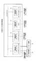
図5には、複数の情報処理装置が仮想的な1台の情報処理装置として動作している様子を示している。ソフトウェアセルの使用による分散処理の結果、同図の上段に示すように、ネットワーク9に接続されている複数の情報処理装置1、2、3、4は、同図の下段に示すように、仮想的な1台の情報処理装置7として動作する。但し、このような仮想的な動作を実現するためには、以下のような構成によって、以下のような処理が実行される必要がある。A-5. Distributed Processing as Network System FIG. 5 shows a state in which a plurality of information processing apparatuses operate as one virtual information processing apparatus. As a result of distributed processing using software cells, as shown in the upper part of the figure, a plurality of
A−6.システムのソフトウェア構成とプログラムのロード
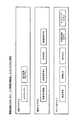
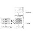
図6には、個々の情報処理コントローラのメインメモリ26が記憶するソフトウェアの構成を示している。これらのソフトウェア(プログラム)は、情報処理装置に電源が投入される前に、当該の情報処理コントローラに接続される外部記録部28に記録されているものである。各プログラムは、機能又は特徴により、制御プログラム、機能プログラム及びデバイスドライバに分類される。A-6. System Software Configuration and Program Loading FIG. 6 shows the software configuration stored in the main memory 26 of each information processing controller. These software (programs) are recorded in the external recording unit 28 connected to the information processing controller before the information processing apparatus is turned on. Each program is classified into a control program, a function program, and a device driver according to functions or features.
制御プログラムは、各情報処理コントローラが同じものを備え、各情報処理コントローラのメインプロセッサ21が実行するもので、後述のMS(マスター/スレーブ)マネージャ及び能力交換プログラムを含む。 The control program is the same for each information processing controller, and is executed by the main processor 21 of each information processing controller, and includes an MS (master / slave) manager and a capacity exchange program described later.
機能プログラムは、メインプロセッサ21が実行するもので、記録用、再生用、素材検索用など、情報処理コントローラ毎に情報処理装置に応じたものが備えられる。 The function program is executed by the main processor 21, and a function program corresponding to the information processing apparatus is provided for each information processing controller such as recording, reproduction, and material search.
デバイスドライバは、情報処理コントローラ(情報処理装置)の入出力(送受信)用で、放送受信、モニタ出力、ビットストリーム入出力、ネットワーク入出力など、情報処理コントローラ毎に情報処理装置に応じたものが備えられる。 The device driver is for input / output (transmission / reception) of the information processing controller (information processing apparatus), such as broadcast reception, monitor output, bit stream input / output, network input / output, etc. Provided.
ケーブルの差し込みなどによって情報処理装置が物理的にネットワーク9に接続された状態で、情報処理装置に主電源が投入され、情報処理装置が電気的・機能的にもネットワーク9に接続されると、その情報処理装置の情報処理コントローラのメインプロセッサ21は、制御プログラムに属する各プログラム、及びデバイスドライバに属する各プログラムを、メインメモリ26にロードする。 When the information processing apparatus is physically connected to the network 9 by plugging in a cable or the like, the main power supply is turned on and the information processing apparatus is electrically and functionally connected to the network 9. The main processor 21 of the information processing controller of the information processing apparatus loads each program belonging to the control program and each program belonging to the device driver into the main memory 26.
プログラムのロード手順としては、メインプロセッサ21は、まず、DC27に読み出し命令を実行させることによって、外部記録部28からプログラムを読み出し、次に、DMAC25に書き込み命令を実行させることによって、そのプログラムをメインメモリ26に書き込む。 As a program loading procedure, the main processor 21 first reads the program from the external recording unit 28 by causing the DC 27 to execute a read command, and then causes the DMAC 25 to execute the write command to Write to memory 26.
機能プログラムに属する各プログラムについては、必要なときに必要なプログラムだけをメモリにロードするように構成してもよく、あるいは他のカテゴリに属するプログラムと同様に、主電源投入直後に各プログラムをロードするように構成してもよい。 As for each program belonging to the function program, it may be configured to load only the necessary program into the memory when necessary, or, like programs belonging to other categories, each program is loaded immediately after the main power is turned on. You may comprise.
機能プログラムに属する各プログラムは、ネットワークに接続されたすべての情報処理装置の外部記録部28に記録されている必要はなく、いずれか1つの情報処理装置の外部記録部28に記録されていれば、前述の方法によって他の情報処理装置からロードすることができるので、結果的に図5の下段に示すように、仮想的な1台の情報処理装置7として機能プログラムを実行することができる。 Each program belonging to the function program does not need to be recorded in the external recording unit 28 of all information processing apparatuses connected to the network, but may be recorded in the external recording unit 28 of any one information processing apparatus. Since it can be loaded from another information processing apparatus by the above-described method, as a result, as shown in the lower part of FIG. 5, the function program can be executed as one virtual information processing apparatus 7.
ここで、前述したようにメインプロセッサ21によって処理される機能プログラムは、サブプロセッサ23によって処理されるサブプロセッサプログラムと連携動作する場合がある。そこでメインプロセッサ21が外部記録部28から機能プログラムを読み出し、メインメモリ26に書き込む際に対象となる機能プログラムと連携動作するサブプロセッサプログラムが存在する場合には、当該サブプロセッサプログラムも併せて同じメインメモリ26に書き込むものとする。この場合、連携動作するサブプロセッサプログラムは1個である場合もあるし、複数個であることもあり得る。複数個である場合には、すべての連携動作するサブプロセッサプログラムをメインメモリ26に書き込むことになる。メインメモリ26に書き込まれたサブプロセッサプログラムはその後、サブプロセッサ23内のLS24に書き込まれ、メインプロセッサ21によって処理される機能プログラムと連携動作する。Here, as described above, the function program processed by the main processor 21 may operate in cooperation with the sub processor program processed by the sub processor 23. Therefore, when the main processor 21 reads out the function program from the external recording unit 28 and writes it to the main memory 26, when there is a sub processor program that operates in cooperation with the target function program, the sub processor program also includes the same main program. It is assumed that data is written in the memory 26. In this case, there may be one or more sub-processor programs that operate in cooperation with each other. If there are a plurality of sub-processor programs, all sub-processor programs that operate in cooperation are written in the main memory 26. The sub processor program written in the main memory 26 is then written in the LS 24 in the sub processor 23 and operates in cooperation with the function program processed by the main processor 21.
そして、サブプロセッサプログラムにもサブプロセッサプログラムIDが割り当てられ、これによりサブプロセッサプログラムを一意的に識別可能である。割り当てられるサブプロセッサプログラムIDは、連携動作する相手となる機能プログラムの機能プログラムIDと関連性のある識別子、例えば機能プログラムIDを親番号とした上で最後尾に枝番号を付加させたものなどであることもあり得るし、連携動作する相手となる機能プログラムの機能プログラムIDとは関連性のない識別子であってもよい。いずれにしても機能プログラムとサブプロセッサプログラムが連携動作する場合には、両者とも相手の識別子であるプログラムIDを自プログラム内に互いに記憶しておく必要がある。機能プログラムが複数個のサブプロセッサプログラムと連携動作する場合にも、当該機能プログラムは複数個ある全てのサブプロセッサプログラムのサブプロセッサプログラムIDを記憶しておくことになる。 A sub processor program ID is also assigned to the sub processor program, whereby the sub processor program can be uniquely identified. The assigned sub-processor program ID is an identifier related to the function program ID of the function program that is the partner of the cooperative operation, for example, the function program ID as a parent number and a branch number added at the end. There may be an identifier that is not related to the function program ID of the function program that is the partner of the cooperative operation. In any case, when the function program and the sub processor program operate in cooperation, it is necessary to store the program ID which is the identifier of the other party in the own program. Even when the function program operates in cooperation with a plurality of sub processor programs, the function program stores the sub processor program IDs of all the sub processor programs.
図3のソフトウェアセルに示したように、機能プログラムには、プログラム毎にプログラムを一意的に識別できる識別子が機能プログラムIDとして割り当てられる。機能プログラムIDは、機能プログラムの作成の段階で、作成日時や情報処理装置IDなどから決定される。 As shown in the software cell of FIG. 3, an identifier that can uniquely identify a program is assigned to each function program as a function program ID. The function program ID is determined from the creation date and time, the information processing apparatus ID, and the like at the stage of creating the function program.
メインプロセッサ21は、自身が動作する情報処理装置の装置情報(動作状態に関する情報)を格納するための領域をメインメモリ26に確保し、当該情報を自装置の装置情報テーブルとして記録する。ここで言う装置情報は、図4に示したステータス返信コマンドのデータ領域における情報処理装置ID以下の各情報である。 The main processor 21 secures an area for storing device information (information regarding the operation state) of the information processing device on which the main processor 21 operates in the main memory 26, and records the information as a device information table of the own device. The device information referred to here is each information below the information processing device ID in the data area of the status reply command shown in FIG.
A−7.システムにおけるマスター/スレーブの決定
上述したネットワークシステムでは、ある情報処理装置への主電源投入時、その情報処理装置の情報処理コントローラのメインプロセッサ21は、マスター/スレーブマネージャ(以下、MSマネージャ)をメインメモリ26にロードし、実行する。A-7. Determination of Master / Slave in the System In the above-described network system, when the main power supply to a certain information processing apparatus is turned on, the main processor 21 of the information processing controller of the information processing apparatus mains the master / slave manager (hereinafter referred to as MS manager). It is loaded into the memory 26 and executed.
MSマネージャは、自身が動作する情報処理装置がネットワーク9に接続されていることを検知すると、同じネットワーク9に接続されている他の情報処理装置の存在を確認する。ここでの「接続」又は「存在」は、上述したように、情報処理装置が物理的にネットワーク9に接続されているだけでなく、電気的・機能的にもネットワーク9に接続されていることを示す。 When the MS manager detects that the information processing apparatus on which it operates is connected to the network 9, it confirms the existence of another information processing apparatus connected to the same network 9. As used herein, “connection” or “presence” means that the information processing apparatus is not only physically connected to the network 9 but also electrically and functionally connected to the network 9. Indicates.
また、自身が動作する情報処理装置を自装置、他の情報処理装置を他装置と称する。当該装置も、当該情報処理装置を示すものとする。 In addition, an information processing apparatus in which the device operates is referred to as a self device, and another information processing device is referred to as another device. The apparatus also indicates the information processing apparatus.
MSマネージャが同じネットワーク9に接続されている他の情報処理装置の存在を確認する方法について以下に説明する。 A method in which the MS manager confirms the presence of another information processing apparatus connected to the same network 9 will be described below.
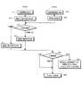
MSマネージャは、DMAコマンドがステータス要求コマンドであり、送信元ID及び応答先IDが当該情報処理装置で、送信先IDを特定しないソフトウェアセルを生成し、当該情報処理装置が接続されたネットワーク上に送信し、ネットワーク接続確認用のタイマーを設定する。タイマーのタイムアウト時間は、例えば10分である。 The MS manager generates a software cell in which the DMA command is a status request command, the transmission source ID and the response destination ID are the information processing apparatus, and the transmission destination ID is not specified, and the information processing apparatus is connected to the network. Send and set a timer for network connection confirmation. The timeout time of the timer is, for example, 10 minutes.
当該ネットワークシステム上に他の情報処理装置が接続されている場合、その他装置は、上記ステータス要求コマンドのソフトウェアセルを受信し、上記応答先IDで特定されるステータス要求コマンドを発行した情報処理装置に対して、DMAコマンドがステータス返信コマンドで、且つデータとして自身(その他装置)の装置情報を含むソフトウェアセルを送信する。このステータス返信コマンドのソフトウェアセルには、少なくとも当該他装置を特定する情報(情報処理装置ID、メインプロセッサに関する情報、サブプロセッサに関する情報など)、及び当該他装置のMSステータスが含まれる。 When another information processing apparatus is connected to the network system, the other apparatus receives the software cell of the status request command, and sends it to the information processing apparatus that has issued the status request command specified by the response destination ID. On the other hand, the DMA command is a status return command, and a software cell including device information of itself (other device) is transmitted as data. The software cell of this status reply command includes at least information for identifying the other device (information processing device ID, information on the main processor, information on the sub processor, etc.) and the MS status of the other device.
ステータス要求コマンドを発行した情報処理装置のMSマネージャは、上記ネットワーク接続確認用のタイマーがタイムアウトするまで、当該ネットワーク上の他装置から送信されるステータス返信コマンドのソフトウェアセルの受信を監視する。その結果、MSステータス=0(マスター装置)を示すステータス返信コマンドが受信された場合には、自装置の装置情報テーブルにおけるMSステータスを1に設定する。これによって、当該装置はスレーブ装置となる。 The MS manager of the information processing apparatus that has issued the status request command monitors the reception of the software cell of the status reply command transmitted from another apparatus on the network until the timer for network connection confirmation times out. As a result, when the status reply command indicating the MS status = 0 (master device) is received, the MS status in the device information table of the own device is set to 1. As a result, the device becomes a slave device.
一方、上記ネットワーク接続確認用のタイマーがタイムアウトするまでの間にステータス返信コマンドがまったく受信されなかった場合、又はMSステータス=0(マスター装置)を示すステータス返信コマンドが受信されなかった場合には、自装置の装置情報テーブルにおけるMSステータスを0に設定する。これによって、当該装置はマスター装置となる。 On the other hand, when no status reply command is received before the network connection confirmation timer times out, or when no status reply command indicating MS status = 0 (master device) is received, The MS status in the device information table of the own device is set to 0. This makes the device a master device.
すなわち、いずれの装置もネットワーク9に接続されていない状態、又はネットワーク9上にマスター装置が存在しない状態において、新たな情報処理装置がネットワーク9に接続されると、当該装置は自動的にマスター装置として設定される。一方、ネットワーク9上に既にマスター装置が存在する状態において、新たな情報処理装置がネットワーク9に接続されると、当該装置は自動的にスレーブ装置として設定される。 That is, if no information processing apparatus is connected to the network 9 in a state in which no apparatus is connected to the network 9 or a master apparatus does not exist on the network 9, the apparatus automatically becomes the master apparatus. Set as On the other hand, when a new information processing apparatus is connected to the network 9 in a state where a master apparatus already exists on the network 9, the apparatus is automatically set as a slave apparatus.
マスター装置及びスレーブ装置のいずれについても、MSマネージャは、定期的にステータス要求コマンドをネットワーク9上の他装置に送信してステータス情報を照会することにより、他装置の状況を監視する。この結果、ネットワーク9に接続されている情報処理装置の主電源が遮断され、又はネットワーク9から情報処理装置が切り離されることにより、あらかじめ判定用に設定された所定期間内に特定の他装置からステータス返信コマンドが返信されなかった場合や、ネットワーク9に新たな情報処理装置が接続された場合など、ネットワーク9の接続状態に変化があった場合には、その情報を後述の能力交換プログラムに通知する。 For both the master device and the slave device, the MS manager periodically monitors the status of the other device by sending a status request command to the other device on the network 9 and inquiring status information. As a result, the main power source of the information processing apparatus connected to the network 9 is cut off or the information processing apparatus is disconnected from the network 9, so that the status from a specific other apparatus is determined within a predetermined period set in advance for determination. When there is a change in the connection state of the network 9, such as when a reply command is not returned or when a new information processing apparatus is connected to the network 9, the information is notified to the ability exchange program described later. .
A−8.マスター装置及びスレーブ装置における装置情報の取得
メインプロセッサ21は、MSマネージャから、ネットワーク9に接続された他の情報処理装置の照会及び自装置のMSステータスの設定完了の通知を受けると、能力交換プログラムを実行する。A-8. Acquisition of device information in the master device and slave device When the main processor 21 receives an inquiry from another MS information processing device connected to the network 9 and a notification of completion of setting of the MS status of its own device, the capability exchange program Execute.
能力交換プログラムは、自装置がマスター装置である場合には、ネットワーク9に接続されている他のすべての情報処理装置についての装置情報、すなわち各スレーブ装置の装置情報を取得する。 When the own device is the master device, the capability exchange program acquires device information about all other information processing devices connected to the network 9, that is, device information of each slave device.
他装置の装置情報の取得は、上述したように、DMAコマンドがステータス要求コマンドであるソフトウェアセルを生成して他装置に送信し、その後、DMAコマンドがステータス返信コマンドで、且つデータとして他装置の装置情報を含むソフトウェアセルを他装置から受信することによって可能である。 As described above, the device information of the other device is obtained by generating a software cell in which the DMA command is a status request command and transmitting it to the other device, and then the DMA command is a status return command and as data. This is possible by receiving a software cell containing device information from another device.
能力交換プログラムは、マスター装置である自装置の装置情報テーブルと同様に、ネットワーク9に接続されている他のすべての装置(各スレーブ装置)についての装置情報を格納するための領域を自装置のメインメモリ26に確保し、これら情報を他装置(スレーブ装置)の装置情報テーブルとして記録する。すなわち、マスター装置のメインメモリ26には、自装置を含むネットワーク9に接続されているすべての情報処理装置の装置情報が装置情報テーブルとして記録される。 The capability exchange program sets an area for storing device information about all other devices (each slave device) connected to the network 9 in the same manner as the device information table of the device that is the master device. This information is secured in the main memory 26 and recorded as a device information table of another device (slave device). That is, the device information of all information processing devices connected to the network 9 including the device itself is recorded in the main memory 26 of the master device as a device information table.
一方、能力交換プログラムは、自装置がスレーブ装置である場合には、ネットワーク9に接続されている他のすべての装置についての装置情報、すなわちマスター装置及び自装置以外の各スレーブ装置の装置情報を取得し、これら装置情報に含まれる情報処理装置ID及びMSステータスを、自装置のメインメモリ26に記録する。すなわち、スレーブ装置のメインメモリ26には、自装置の装置情報が、装置情報テーブルとして記録されるとともに、自装置以外のネットワーク9に接続されているマスター装置及び各スレーブ装置についての情報処理装置ID及びMSステータスが、別の装置情報テーブルとして記録される。 On the other hand, when the own device is a slave device, the capability exchange program obtains device information about all other devices connected to the network 9, that is, device information of each slave device other than the master device and the own device. The information processing apparatus ID and the MS status included in the apparatus information are acquired and recorded in the main memory 26 of the own apparatus. That is, the device information of the own device is recorded as a device information table in the main memory 26 of the slave device, and the master device connected to the network 9 other than the own device and the information processing device ID for each slave device. And the MS status are recorded as another device information table.
また、マスター装置及びスレーブ装置のいずれについても、能力交換プログラムは、上記のようにMSマネージャから、新たにネットワーク9に情報処理装置が接続されたことが通知されたときには、その情報処理装置の装置情報を取得し、上述したようにメインメモリ26に記録する。 Further, in both the master device and the slave device, when the capability exchange program is notified from the MS manager that the information processing device is newly connected to the network 9 as described above, the device of the information processing device Information is acquired and recorded in the main memory 26 as described above.
なお、MSマネージャ及び能力交換プログラムは、メインプロセッサ21で実行されることに限らず、いずれかのサブプロセッサ23で実行されてもよい。また、MSマネージャ及び能力交換プログラムは、情報処理装置の主電源が投入されている間は常時動作する常駐プログラムであることが望ましい。 Note that the MS manager and the capability exchange program are not limited to being executed by the main processor 21, but may be executed by any of the sub processors 23. The MS manager and the capability exchange program are preferably resident programs that always operate while the main power supply of the information processing apparatus is turned on.
A−9.情報処理装置がネットワークから切断された場合
マスター装置及びスレーブ装置のいずれについても、能力交換プログラムは、上記のようにMSマネージャから、ネットワーク9に接続されている情報処理装置の主電源が遮断され、又はネットワーク9から情報処理装置が切り離されたことが通知されたときには、その情報処理装置の装置情報テーブルを自装置のメインメモリ26から削除する。A-9. When the information processing device is disconnected from the network , for both the master device and the slave device, the mains power of the information processing device connected to the network 9 is shut off from the MS manager as described above. Alternatively, when it is notified from the network 9 that the information processing apparatus has been disconnected, the apparatus information table of the information processing apparatus is deleted from the main memory 26 of the own apparatus.
さらに、このようにネットワーク9から切断された情報処理装置がマスター装置である場合には、以下のような方法によって、新たにマスター装置が決定される。 Further, when the information processing apparatus disconnected from the network 9 is a master apparatus, a new master apparatus is determined by the following method.
例えば、ネットワーク9から切断されていない情報処理装置は、それぞれ、自装置及び他装置の情報処理装置IDを数値に置き換え、自装置の情報処理装置IDを他装置の情報処理装置IDと比較し、自装置の情報処理装置IDがネットワーク9から切断されていない情報処理装置中で最小である場合、そのスレーブ装置は、マスター装置に移行し、MSステータスを0に設定し、マスター装置として、上述したように、ネットワーク9に接続されている他のすべての情報処理装置(各スレーブ装置)から装置情報を取得して、メインメモリ26に記録する。 For example, each of the information processing devices that are not disconnected from the network 9 replaces the information processing device ID of the own device and the other device with a numerical value, compares the information processing device ID of the own device with the information processing device ID of the other device, and When the information processing device ID of the own device is the smallest among the information processing devices that are not disconnected from the network 9, the slave device moves to the master device, sets the MS status to 0, and is described above as the master device. As described above, device information is acquired from all other information processing devices (each slave device) connected to the network 9 and recorded in the main memory 26.
A−10.装置情報に基づく分散処理
図5の下段に示したようにネットワーク9に接続されている複数の情報処理装置1、2、3、4を仮想的な1台の情報処理装置7として動作させるためには、マスター装置がユーザの操作及びスレーブ装置の動作状態を把握する必要がある。A-10. Distributed processing based on device information To operate a plurality of
図7には、4台の情報処理装置が仮想的な1台の情報処理装置7として動作する様子を示している。図示の例では、情報処理装置1がマスター装置、情報処理装置2、3、4がスレーブ装置A、B、Cとしてそれぞれ動作しているものとする。 FIG. 7 shows a state in which four information processing apparatuses operate as one virtual information processing apparatus 7. In the illustrated example, it is assumed that the
ユーザがネットワーク9に接続されている情報処理装置を操作した場合、操作対象がマスター装置1であれば、その操作情報はマスター装置1において直接把握される。また、操作対象がスレーブ装置であれば、その操作情報は操作されたスレーブ装置からマスター装置1に送信される。すなわち、ユーザの操作対象がマスター装置1とスレーブ装置のいずれであるかにかかわらず、その操作情報は常にマスター装置1において把握される。操作情報の送信は、例えば、DMAコマンドが操作情報送信コマンドであるソフトウェアセルによって行なわれる。 When a user operates an information processing apparatus connected to the network 9, if the operation target is the
そして、マスター装置1内の情報処理コントローラ11に含まれるメインプロセッサ21−1は、その操作情報に従って、実行する機能プログラムを選択する。その際、必要であれば、マスター装置1内の情報処理コントローラ11に含まれるメインプロセッサ21−1は、上記の方法によって自装置の外部記録部28−1、28−2からメインメモリ26−1に機能プログラムをロードするが、他の情報処理装置(スレーブ装置)がマスター装置1に機能プログラムを送信してもよい。 Then, the main processor 21-1 included in the
機能プログラムには、その実行単位毎に必要となる、情報処理装置種別ID、メインプロセッサ又はサブプロセッサの処理能力、メインメモリ使用量、外部記録部に関する条件などの装置に関する要求スペック(図4を参照のこと)が規定されている。 In the function program, required specifications related to the device such as information processing device type ID, main processor or sub-processor processing capacity, main memory usage, and conditions related to the external recording unit required for each execution unit (see FIG. 4) Is defined).
マスター装置1内の情報処理コントローラ11に含まれるメインプロセッサ21−1は、各機能プログラムについて必要となる上記の要求スペックを読み出す。また、あらかじめ能力交換プログラムによってメインメモリ26−1に記録された装置情報テーブルを参照し、各情報処理装置の装置情報を読み出す。ここでの装置情報は、図4に示した情報処理装置ID以下の各情報を示し、メインプロセッサ、サブプロセッサ、メインメモリ及び外部記録部に関する情報である。 The main processor 21-1 included in the
マスター装置1内の情報処理コントローラ11に含まれるメインプロセッサ21−1は、ネットワーク9上に接続された各情報処理装置の上記装置情報と、機能プログラム実行に必要となる上記要求スペックとを順次比較する。 The main processor 21-1 included in the
例えば、機能プログラムが録画機能を必要とする場合には、情報処理装置種別IDに基づいて、録画機能を有する情報処理装置のみを特定して抽出する。さらに、機能プログラムを実行するために必要なメインプロセッサ又はサブプロセッサの処理能力、メインメモリ使用量、外部記録部に関する条件を確保できるスレーブ装置を、実行要求候補装置として特定する。ここで、複数の実行要求候補装置が特定された場合には、当該候補装置から1つの実行要求候補装置を特定して選択する。 For example, when the function program requires a recording function, only the information processing apparatus having the recording function is specified and extracted based on the information processing apparatus type ID. Furthermore, a slave device that can ensure the conditions regarding the processing capability of the main processor or sub processor, the amount of main memory used, and the external recording unit necessary for executing the function program is specified as an execution request candidate device. Here, when a plurality of execution request candidate devices are specified, one execution request candidate device is specified and selected from the candidate devices.
実行要求するスレーブ装置が特定されたら、マスター装置1内の情報処理コントローラ11に含まれるメインプロセッサ21−1は、その特定されたスレーブ装置について、自装置内の情報処理コントローラ11に含まれるメインメモリ26−1に記録されている当該スレーブ装置の装置情報テーブルを更新する。 When the slave device to be executed is specified, the main processor 21-1 included in the
さらに、マスター装置1内の情報処理コントローラ11に含まれるメインプロセッサ21−1は、DMAコマンドが機能プログラム実行コマンドであるソフトウェアセルを生成し、当該ソフトウェアセルのセルインターフェースに、当該機能プログラムに関する必要なサブプロセッサの情報及びサンドボックスサイズ(図3を参照のこと)を設定し、上記実行要求されるスレーブ装置に対して送信する。 Further, the main processor 21-1 included in the
機能プログラムの実行を要求されたスレーブ装置は、その機能プログラムを実行するとともに、自装置の装置情報テーブルを更新する。その際、必要であれば、スレーブ装置内の情報処理コントローラに含まれるメインプロセッサ21は、上記の方法によって自装置の外部記録部28からメインメモリ26に機能プログラムおよび当該機能プログラムと連携動作するサブプロセッサプログラムをロードする。 The slave device requested to execute the function program executes the function program and updates the device information table of the own device. At that time, if necessary, the main processor 21 included in the information processing controller in the slave device, from the external recording unit 28 of the own device to the main memory 26 by the above method, the function program and the sub-operation that operates in cooperation with the function program. Load the processor program.
機能プログラムの実行を要求されたスレーブ装置の外部記録部28に必要な機能プログラム又は当該機能プログラムと連携動作するサブプロセッサプログラムが記録されていない場合には、他の情報処理装置が当該機能プログラム又はサブプロセッサプログラムをその機能プログラム実行要求先スレーブ装置に送信するように、システムを構成すればよい。 When the necessary function program or the sub processor program that operates in cooperation with the function program is not recorded in the external recording unit 28 of the slave device requested to execute the function program, the other information processing apparatus The system may be configured to transmit the sub-processor program to the functional program execution request destination slave device.
サブプロセッサプログラムについては、前述のロードコマンド及びキックコマンドを利用して他の情報処理装置に実行させることもできる。 The sub-processor program can be executed by another information processing apparatus using the aforementioned load command and kick command.
機能プログラムの実行終了後、機能プログラムを実行したスレーブ装置内の情報処理コントローラに含まれるメインプロセッサ21は、終了通知をマスター装置1内の情報処理コントローラ11に含まれるメインプロセッサ21−1に送信するとともに、自装置の装置情報テーブルを更新する。マスター装置1内の情報処理コントローラ11に含まれるメインプロセッサ21−1は、その終了通知を受信して、機能プログラムを実行したスレーブ装置の装置情報テーブルを更新する。 After the execution of the function program, the main processor 21 included in the information processing controller in the slave device that has executed the function program transmits an end notification to the main processor 21-1 included in the
マスター装置1内の情報処理コントローラ11に含まれるメインプロセッサ21−1は、自装置及び他装置の装置情報テーブルの参照結果から、当該の機能プログラムを実行することができる情報処理装置として、自身を選択する場合もあり得る。その場合には、マスター装置1が当該の機能プログラムを実行する。 The main processor 21-1 included in the
図7に示した例で、ユーザがスレーブ装置A(情報処理装置2)を操作し、当該操作に応じた機能プログラムを別のスレーブ装置B(情報処理装置3)が実行する場合の分散処理について、図8を参照しながら説明する。 In the example illustrated in FIG. 7, distributed processing when the user operates slave device A (information processing device 2) and another slave device B (information processing device 3) executes a function program corresponding to the operation. This will be described with reference to FIG.
図8に示す例では、ユーザがスレーブ装置Aを操作することにより、スレーブ装置Aを含むネットワークシステム全体の分散処理が開始し、まず、スレーブ装置Aは、その操作情報をマスター装置1に送信する(ステップ81)。 In the example illustrated in FIG. 8, when the user operates the slave device A, distributed processing of the entire network system including the slave device A starts. First, the slave device A transmits the operation information to the
マスター装置1は、その操作情報を受信し(ステップ72)、さらに自装置のメインメモリ26−1に記録されている自装置及び他装置の装置情報テーブルから各情報処理装置の動作状態を調べ、受信した操作情報に応じた機能プログラムを実行することができる情報処理装置を選択する(ステップ73)。図示の例では、スレーブ装置Bが選択される場合を示している。 The
次に、マスター装置1は、その選択したスレーブ装置Bに対して機能プログラムの実行を要求する(ステップ74)。 Next, the
スレーブ装置Bは、その実行要求を受信し(ステップ95)、さらに、実行要求された機能プログラムを実行する(ステップ96)。 The slave device B receives the execution request (step 95), and further executes the function program requested to be executed (step 96).
以上のように、ユーザは、1台の情報処理装置のみを操作することによって、他の情報処理装置を操作することなく、複数の情報処理装置1、2、3、4を仮想的な1台の情報処理装置7として動作させることができる。 As described above, by operating only one information processing apparatus, the user operates a plurality of
A−11.各情報処理装置及びシステムの具体例
ネットワーク9を介して互いに接続される情報処理装置1、2、3、4は、上記のような情報処理コントローラ11、12、13、14によって情報処理を行なうものであれば、基本的にはどのような構成でもよい。図9には、情報処理装置の一構成例を示している。A-11. Specific examples of information processing apparatuses and systems
情報処理コントローラ11を備える情報処理装置1の一例は、ハードディスクレコーダである。図10並びに図11には、同図中のハードディスクレコーダのハードウェア構成及びソフトウェア構成をそれぞれ示している。ハードディスクレコーダのハードウェア構成としては、図1に示した外部記録部28−1としてハードディスクを内蔵し、図1に示した外部記録部28−2としてDVD±R/RW、CD±R/RW、Bluray−Disc(登録商標)などの光ディスクを装着できるように構成されるとともに、情報処理コントローラ11のバス29−1に接続されたバス31−1に、放送受信部32−1、映像入力部33−1、音声入力部34−1、映像出力部35−1、音声出力部36−1、操作パネル部37−1、リモコン受光部38−1及びネットワーク接続部39−1が接続されている。 An example of the
放送受信部32−1、映像入力部33−1及び音声入力部34−1は、放送信号を受信し、又は情報処理装置1の外部から映像信号及び音声信号を入力し、それぞれ所定フォーマットのデジタルデータに変換し、情報処理コントローラ11での処理のためにバス31−1に送出する。映像出力部35−1及び音声出力部36−1は、情報処理コントローラ11からバス31−1に送出された映像データ及び音声データを処理して、デジタルデータのまま、又はアナログ信号に変換して、情報処理装置1の外部に送出するものであり、リモコン受光部38−1は、リモコン送信器43−1からのリモコン(遠隔操作)赤外線信号を受信する。 The broadcast receiving unit 32-1, the video input unit 33-1 and the audio input unit 34-1 receive a broadcast signal or input a video signal and an audio signal from the outside of the
図9及び図10に示すように、情報処理装置(ハードディスクレコーダ)1の映像出力部35−1及び音声出力部36−1には、モニタ表示装置41及びスピーカ装置42が接続される。 As shown in FIGS. 9 and 10, a
図9に例示した情報処理コントローラ12を備える情報処理装置2も、ハードディスクレコーダで、図10において括弧内に参照番号を付して示すように、情報処理装置1と同様に構成される。但し、図9に示すように、情報処理装置(ハードディスクレコーダ)2には、モニタ表示装置及びスピーカ装置は接続されない。 The
情報処理装置(ハードディスクレコーダ)1及び2、すなわち情報処理コントローラ11及び12のソフトウェア構成としては、図11に示すように、制御プログラムとして、MSマネージャ及び能力交換プログラムを備え、機能プログラムとして、映像音声記録、映像音声再生、素材検索及び番組録画予約のためのプログラムを備え、デバイスドライバとして、放送受信、映像出力、音声出力、外部記録部入出力及びネットワーク入出力のためのプログラムを備える。 As shown in FIG. 11, the software configuration of the information processing apparatuses (hard disk recorders) 1 and 2, that is, the
また、情報処理コントローラ13を備える情報処理装置3の他の例は、PDA(Personal Digital Assistants)である。図12には、PDAとして構成される情報処理装置3のハードウェア構成を示している。同図に示す例では、図1に示した外部記録部28−5として、メモリカードディスクを装着できるように構成され、情報処理コントローラ13のバス29−3に接続されたバス51に、液晶表示部52、音声出力部53、カメラ部54、音声入力部55、キーボード部56及びネットワーク接続部57が接続されている。 Another example of the
なお、図1では内部を省略した情報処理コントローラ13は、メインプロセッサ21−3、サブプロセッサ23−7、23−8、23−9、DMAC(ダイレクトメモリアクセスコントローラ)25−3、DC(ディスクコントローラ)27−3及びバス29−3を備え、そのメインプロセッサ21−3は、LS(ローカル・ストレージ)22−3を有し、各サブプロセッサ23−7、23−8、23−9は、LS(ローカル・ストレージ)24−7、24−8、24−9を備えている。 Note that the
また、図13には、情報処理装置(PDA)3、すなわち情報処理コントローラ13のソフトウェア構成を示している。同図に示すように、制御プログラムとして、MSマネージャ及び能力交換プログラムを備え、機能プログラムとして、映像音声記録、映像音声再生、電話帳、ワープロ及び表計算のためのプログラム、及びWebブラウザを備え、デバイスドライバとして、映像出力、音声出力、カメラ映像入力、マイク音声入力及びネットワーク入出力のためのプログラムを備えている。 FIG. 13 shows a software configuration of the information processing apparatus (PDA) 3, that is, the
また、情報処理コントローラ14を備える情報処理装置4は、ポータブルCDプレーヤである。図14には、ポータブルCDプレーヤのハードウェア構成を示している。図示の例では、ポータブルCDプレーヤは、図1に示した外部記録部28−6として、CD(Compact Disc)を装着できるように構成され、情報処理コントローラ14のバス29−4に接続されたバス61に、液晶表示部62、音声出力部63、操作ボタン部64及びネットワーク接続部65が接続されている。 The information processing apparatus 4 including the
なお、図1では内部を省略した情報処理コントローラ14は、メインプロセッサ21−4、サブプロセッサ23−10、23−11、23−12、DMAC25−4、DC27−4及びバス29−4を備え、そのメインプロセッサ21−4は、LS22−4を有し、各サブプロセッサ23−10、23−11、23−12は、LS24−10、24−11、24−12を有する。 Note that the
図15には、情報処理装置(ポータブルCDプレーヤ)4、すなわち情報処理コントローラ14のソフトウェア構成を示している。図示のように、制御プログラムとして、MSマネージャ及び能力交換プログラムを備え、機能プログラムとして、音楽再生のためのプログラムを備え、デバイスドライバとして、音声出力、CD制御及びネットワーク入出力のためのプログラムを備える。 FIG. 15 shows a software configuration of the information processing apparatus (portable CD player) 4, that is, the
図9に例示したネットワークシステムでは、情報処理装置1、3及び4がネットワーク9上に接続されており、情報処理装置1がマスター装置(MSステータス=0)として、情報処理装置3及び4がスレーブ装置(MSステータス=1)として、設定されているものとする。 In the network system illustrated in FIG. 9, the
この状態で、新たに情報処理装置2がネットワーク9に接続されると、上述した方法によって、情報処理装置2内の情報処理コントローラ12に含まれるメインプロセッサ21−2で実行されているMSマネージャは、他の情報処理装置1、3及び4にMSステータスを照会して、情報処理装置1が既にマスター装置として存在することを認識し、自装置(情報処理装置2)をスレーブ装置(MSステータス=1)に設定する。また、マスター装置に設定されている情報処理装置1は、新たに追加された情報処理装置2を含む各装置の装置情報を収集して、メインメモリ26−1内の装置情報テーブルを更新する。 In this state, when the
このような状態で、ユーザによってスレーブ装置である情報処理装置(PDA)3で2時間の放送番組を録画予約するための操作が行なわれた場合について、以下に説明する。 In this state, a case where an operation for making a recording reservation for a 2-hour broadcast program is performed by the information processing apparatus (PDA) 3 as a slave apparatus by the user will be described below.
この場合、スレーブ装置である情報処理装置(PDA)3は、ユーザから録画開始時刻、録画終了時刻、録画対象放送チャネル、録画品質などの情報を含む録画予約情報の入力を受け付け、当該録画予約情報及びDMAコマンドとしての録画予約コマンドを含むソフトウェアセルを生成して、マスター装置である情報処理装置1に送信する。 In this case, the information processing apparatus (PDA) 3 which is a slave apparatus receives input of recording reservation information including information such as a recording start time, a recording end time, a recording target broadcast channel, and recording quality from the user, and the recording reservation information A software cell including a recording reservation command as a DMA command is generated and transmitted to the
DMAコマンドが録画予約コマンドであるソフトウェアセルを受信した情報処理装置1内の情報処理コントローラ11に含まれるメインプロセッサ21−1は、録画予約コマンドを読み出すとともに、メインメモリ26−1内の装置情報テーブルを参照し、当該録画予約コマンドを実行可能な情報処理装置を特定する。 The main processor 21-1 included in the
まず、メインプロセッサ21−1は、装置情報テーブルに含まれる各情報処理装置1、2、3、4の情報処理装置種別IDを読み出して、録画予約コマンドに対応する機能プログラムを実行可能な情報処理装置を抽出する。ここでは、録画機能を示す情報処理装置種別IDを有する情報処理装置1、2が候補装置として特定され、情報処理装置3、4は候補装置から除外される。 First, the main processor 21-1 reads information processing device type IDs of the
次に、マスター装置である情報処理装置1内の情報処理コントローラ11に含まれるメインプロセッサ21−1は、装置情報テーブルを参照して、情報処理装置1、2のメインプロセッサ又はサブプロセッサの処理能力、メインメモリに関する情報などの装置に関する情報を読み出し、情報処理装置1、2が録画予約コマンドに対応する機能プログラムの実行に必要な要求スペックを満足するか否かを判断する。ここでは、情報処理装置1、2とも、録画予約コマンドに対応する機能プログラムの実行に必要な要求スペックを満足するものとする。 Next, the main processor 21-1 included in the
さらに、メインプロセッサ21−1は、装置情報テーブルを参照して、情報処理装置1、2の外部記録部に関する情報を読み出し、外部記録部の空き容量が当該録画予約コマンドの実行に必要な容量を満足するか否かを判断する。情報処理装置1、2はハードディスクレコーダであるので、それぞれハードディスク28−1、28−3の、総容量と使用量との差分が、それぞれの空き容量に相当する。 Further, the main processor 21-1 refers to the device information table, reads out information related to the external recording unit of the
この場合、情報処理装置1のハードディスク28−1の空き容量が、録画時間に換算して10分であり、情報処理装置2のハードディスク28−3の空き容量が、録画時間に換算して20時間であるとする。 In this case, the free capacity of the hard disk 28-1 of the
このとき、マスター装置である情報処理装置1内の情報処理コントローラ11に含まれるメインプロセッサ21−1は、当該録画予約コマンドの実行に必要な2時間分の空き容量を確保できる情報処理装置を、実行要求先スレーブ装置として特定する。 At this time, the main processor 21-1 included in the
その結果、情報処理装置2のみが実行要求先スレーブ装置として選択され、マスター装置である情報処理装置1内の情報処理コントローラ11に含まれるメインプロセッサ21−1は、ユーザにより操作された情報処理装置3から送信された録画予約情報を含む当該録画予約コマンドを情報処理装置2に送信して、上記2時間の放送番組の録画予約の実行を要求する。 As a result, only the
そして、情報処理装置2内の情報処理コントローラ12に含まれるメインプロセッサ21−2は、当該録画予約コマンドを解析して、録画に必要な機能プログラムを外部記録部であるハードディスク28−3からメインメモリ26−2にロードし、録画予約情報に従って録画を実行する。その結果、録画予約された2時間の放送番組の映像音声データが情報処理装置2のハードディスク28−3に記録される。 Then, the main processor 21-2 included in the
このように、図9の例のネットワークシステムにおいても、ユーザは、1台の情報処理装置のみを操作することによって、他の情報処理装置を操作することなく、複数の情報処理装置1、2、3、4を仮想的な1台の情報処理装置7として動作させることができる。 As described above, also in the network system of the example of FIG. 9, the user operates only one information processing apparatus, and operates a plurality of
B.仮想的な1台の情報処理装置における拡張機能の実現
上述したように、本発明によれば、ネットワーク接続された複数の情報処理装置が互いに連携することで1台の仮想的な情報処理装置を実現することができる。B. As described aboverealizes the extension in the virtual single information processing apparatus, according to the present invention, one by multiple networked information processing apparatuses cooperate with each other a virtual information processing apparatus Can be realized.
本発明のさらなる実施形態として、仮想情報処理装置を構成する少なくとも1つの情報処理装置は、自装置の物理記憶装置の物理記憶空間上に他の情報処理装置の使用を許可する公開領域を形成するようにした。ここで言う物理記憶装置には、メインメモリやその他のローカルメモリ、ハードディスクなどの外部記憶装置、さらには自装置にローカル接続される各機器への入出力を割り当てたI/O空間が含まれ、連携動作を行なう情報処理装置の間で、これらの情報資源を共有することが可能となる。 As a further embodiment of the present invention, at least one information processing apparatus constituting the virtual information processing apparatus forms a public area that permits the use of another information processing apparatus in the physical storage space of the physical storage apparatus of the own apparatus. I did it. The physical storage device mentioned here includes an external storage device such as a main memory and other local memories, a hard disk, and an I / O space assigned to input / output to each device locally connected to the own device, It is possible to share these information resources between information processing apparatuses that perform cooperative operations.
このような情報資源の共有は、公開領域を要求する情報処理装置と、公開領域を提供する情報処理装置との間における、要求及び許可応答に関する所定のハンドシェイク手順に従って実現される。このハンドシェイク手順には、情報処理装置間の相互認証などの処理を含んでもよい。 Such sharing of information resources is realized according to a predetermined handshake procedure regarding a request and a permission response between an information processing apparatus requesting a public area and an information processing apparatus providing a public area. This handshake procedure may include processing such as mutual authentication between information processing apparatuses.
各情報処理装置は、1以上の物理記憶装置を備えており(前述)、通常は各物理記憶装置の物理記憶空間すなわち物理セグメントアドレスを、論理的な記憶空間すなわち仮想アドレス空間にマッピングし、この仮想アドレス空間上で処理の実行が行なわれる。本実施形態では、情報処理装置が他の情報処理装置から公開領域の使用が許可されたときには、他の情報処理装置の物理アドレス空間に存在する公開領域を自装置の仮想アドレス空間にマッピングして使用する。すなわち、情報処理装置は、他の情報処理装置から得た公開領域の物理セグメントアドレスを、自装置の仮想アドレス空間の仮想セグメントアドレスにマッピングして使用する。 Each information processing apparatus includes one or more physical storage devices (described above), and usually maps the physical storage space of each physical storage device, that is, the physical segment address, to the logical storage space, that is, the virtual address space. Processing is executed in the virtual address space. In the present embodiment, when the information processing apparatus is permitted to use the public area by another information processing apparatus, the public area existing in the physical address space of the other information processing apparatus is mapped to the virtual address space of the own apparatus. use. That is, the information processing apparatus uses the physical segment address of the public area obtained from the other information processing apparatus by mapping it to the virtual segment address in its own virtual address space.
このセグメント変換の仕組みは、以下の通りである。公開領域を他の情報処理装置に提供する情報処理装置側では、物理記憶空間上で公開領域に割り当てられた物理セグメントアドレスに対し公開領域アドレスを割り当てる。この公開領域アドレスは、ネットワーク上すなわち仮想情報処理装置上では、情報処理装置を一意に識別する情報処理装置IDなどからなる宛先IDと当該装置上での公開領域アドレスの組み合わせとしてアドレス表現がなされる。また、他の情報処理装置が提供する公開領域を使用する情報処理装置側では、宛先IDと当該装置上での公開領域アドレスの組み合わせからなるアドレス表現を仮想セグメントアドレスに変換する。 The mechanism of this segment conversion is as follows. On the information processing apparatus side that provides the public area to other information processing apparatuses, the public area address is assigned to the physical segment address assigned to the public area in the physical storage space. This public area address is expressed as an address on the network, that is, on the virtual information processing apparatus, as a combination of a destination ID including an information processing apparatus ID that uniquely identifies the information processing apparatus and a public area address on the apparatus. . In addition, on the information processing apparatus side that uses the public area provided by another information processing apparatus, an address expression composed of a combination of the destination ID and the public area address on the apparatus is converted into a virtual segment address.
公開領域を提供する情報処理装置と、公開領域を使用する情報処理装置の双方のセグメント変換部がネットワーク経由で連携動作することにより、公開領域を使用する情報処理装置側では、仮想セグメントアドレスのみを使用することによって、自装置内のローカルメモリと他の情報処理装置の公開領域のいずれにも透過的にアクセスすることができる。すなわち、ネットワークを介して遠隔に配置されている公開領域が透過的となり、自装置内のローカルメモリと区別することなくアクセスすることが可能となる。 The segment conversion unit of both the information processing device that provides the public area and the information processing device that uses the public area cooperates via the network so that only the virtual segment address is obtained on the information processing device side that uses the public area. By using it, it is possible to transparently access both the local memory in the own apparatus and the public area of another information processing apparatus. That is, a public area remotely located via the network becomes transparent, and can be accessed without being distinguished from the local memory in the own apparatus.
例えば、ある情報処理装置において、仮想アドレス空間にマッピングされている他の情報処理装置の公開領域へのアクセス要求が行なわれたときには、まず、アクセス要求された仮想セグメントアドレスを宛先ID及び公開領域アドレスからなるアドレス表現に変換し、宛先IDで指定される情報処理装置に対し、アクセス要求を行なう。 For example, when a request is made to access a public area of another information processing apparatus mapped in the virtual address space in a certain information processing apparatus, first, the virtual segment address requested to be accessed is set to the destination ID and the public area address. And an access request is made to the information processing apparatus specified by the destination ID.
そして、アクセス要求を受理した情報処理装置側では、公開領域アドレスを自装置内の物理セグメントアドレスに変換し、該当する物理セグメントからデータを取得することができる。その後、物理セグメントを公開領域アドレスに変換し、宛先ID及び公開領域アドレスで取得されたデータとして、要求元の情報処理装置へ返す。要求元の情報処理装置では、宛先ID及び公開領域アドレスを仮想セグメントアドレスに変換し、要求元のアプリケーションなどに対しては仮想セグメントから取得されたデータとして返す。 Then, the information processing apparatus that has received the access request can convert the public area address into a physical segment address in its own apparatus and acquire data from the corresponding physical segment. Thereafter, the physical segment is converted into a public area address, and is returned to the requesting information processing apparatus as data acquired with the destination ID and the public area address. In the request source information processing apparatus, the destination ID and the public area address are converted into a virtual segment address and returned to the request source application as data acquired from the virtual segment.
なお、公開領域を形成した情報処理装置は、自分の公開領域を分割し、他の複数の情報処理装置に対して同時に使用許可を与えるようにしてもよい。また、情報処理装置は、他の2以上の情報処理装置が形成した公開領域の使用を要求し、使用が許可された2以上の情報処理装置の公開領域を同時に使用するようにしてもよい。 Note that the information processing apparatus that has formed the public area may divide its public area and grant use permission to a plurality of other information processing apparatuses at the same time. Further, the information processing apparatus may request use of a public area formed by two or more other information processing apparatuses, and may use the public areas of two or more information processing apparatuses permitted to be used at the same time.
図16には、本発明の一実施形態に係るネットワークシステムの構成を模式的に示している。 FIG. 16 schematically shows the configuration of a network system according to an embodiment of the present invention.
図示のネットワークシステムは、ホームネットワークなどのローカルネットワーク30により相互接続されたセットトップボックス(STB)やAV機器など複数の情報処理装置10、11…が互いに連携することで1台の仮想的な情報処理装置20を構築している。このような場合、2台以上の情報処理装置10、11において分散して保持される情報を公開領域に置くことにより、ユーザから見れば仮想的に1台の機器が保持する情報として取り扱うことができる。 In the illustrated network system, a plurality of
次に、情報処理装置が公開領域を形成するための処理について、図17並びに図18を参照しながら説明する。 Next, processing for the information processing apparatus to form a public area will be described with reference to FIGS. 17 and 18.
情報処理装置は、メインメモリ内で例えばオペレーティングシステムで使用されていない未使用領域を公開領域に割り当てる。そして、メインメモリ上で公開領域に割り当てられた物理セグメントアドレスに対し公開領域アドレスを割り当てる。この公開領域アドレスは、ネットワーク上すなわち仮想情報処理装置上では、情報処理装置を一意に識別する情報処理装置IDなどからなる宛先IDと情報サイズ番号の組み合わせとしてアドレス表現がなされる。 The information processing apparatus allocates, to the public area, an unused area that is not used by the operating system, for example, in the main memory. Then, a public area address is assigned to the physical segment address assigned to the public area on the main memory. This public area address is expressed as an address on the network, that is, on the virtual information processing apparatus, as a combination of a destination ID including an information processing apparatus ID that uniquely identifies the information processing apparatus and an information size number.
一方、メインメモリ内に未使用領域がない情報処理装置は、他の情報処理装置に対し公開領域の使用を要求する。この使用要求が許可され、公開領域を獲得することができたときには、宛先IDと情報サイズ番号の組み合わせからなる公開領域アドレスを仮想セグメントアドレスに変換し、公開領域を仮想アドレス空間に配置する。この結果、情報処理装置上では、ネットワークを介して遠隔に配置されている公開領域が透過的となり、自装置内の物理メモリと区別することなくアクセスすることが可能となる。 On the other hand, an information processing apparatus that has no unused area in the main memory requests other information processing apparatuses to use a public area. When this use request is permitted and the public area can be acquired, the public area address composed of the combination of the destination ID and the information size number is converted into a virtual segment address, and the public area is arranged in the virtual address space. As a result, on the information processing apparatus, the public area remotely located via the network becomes transparent and can be accessed without being distinguished from the physical memory in the own apparatus.
例えば、公開データ並びに非公開データを含むさまざまなデータを管理するサーバなどの装置は、公開データを公開領域で保持することで、仮想的に1台として動作する他の情報処理装置と情報の共有を容易に実現することができる(図19を参照のこと)。すなわち、サーバはスレーブに情報や領域を公開し、クライアントはサーバが公開した情報や領域を読み出し、実行することができる。また、クライアントが代理サーバとなり、他のクライアントに公開することも可能である。 For example, a device such as a server that manages various data including public data and non-public data shares information with other information processing devices that operate virtually as a single unit by holding the public data in the public area. Can be easily realized (see FIG. 19). That is, the server can disclose information and areas to the slave, and the client can read and execute information and areas disclosed by the server. In addition, the client can act as a proxy server and can be disclosed to other clients.
図20には、ネットワーク接続され連携動作する2台のセットトップボックス(STB)の一方STB(a)がサーバ、他方STB(b)がクライアントとなり、STB(b)にSTB(a)の情報をマッピングした様子を示している。 In FIG. 20, one STB (a) of two set-top boxes (STB) connected in a network and operating in cooperation is a server, the other STB (b) is a client, and STB (b) information is stored in STB (b). The mapping is shown.
公開領域を形成した情報処理装置は、自分の公開領域を分割し、他の複数の情報処理装置に対して同時に使用許可を与えるようにしてもよい。図21には、1台のセットトップボックスSTB(a)が2台のセットトップボックスSTB(b)及びSTB(c)に公開領域の使用を許可している様子を示している。 The information processing apparatus that has formed the public area may divide its public area and grant use permission to a plurality of other information processing apparatuses at the same time. FIG. 21 shows a state where one set-top box STB (a) permits two set-top boxes STB (b) and STB (c) to use a public area.
また、情報処理装置は、他の2以上の情報処理装置が形成した公開領域の使用を要求し、使用が許可された2以上の情報処理装置の公開領域を同時に使用するようにしてもよい。図22には、1台のセットトップボックスSTB(b)が2台のセットトップボックスSTB(a)及びSTB(c)から使用が許可された公開領域を使用している様子を示している。 Further, the information processing apparatus may request use of a public area formed by two or more other information processing apparatuses, and may use the public areas of two or more information processing apparatuses permitted to be used at the same time. FIG. 22 shows a state in which one set-top box STB (b) uses a public area permitted to be used by two set-top boxes STB (a) and STB (c).
1台の仮想情報処理装置として連携動作する情報処理装置同士において、上述したような情報資源の共有を行なう際には、公開領域を要求する情報処理装置と、公開領域を提供する情報処理装置との間における、要求及び許可応答に関する所定のハンドシェイク手順に従って実現される。このハンドシェイク手順について、図23を参照しながら説明する。 When information resources such as those described above are shared among information processing apparatuses that operate cooperatively as a single virtual information processing apparatus, an information processing apparatus that requests a public area, and an information processing apparatus that provides the public area Is implemented according to a predetermined handshake procedure for requests and grant responses during This handshake procedure will be described with reference to FIG.
公開領域を提供する側の情報処理装置STB(a)側では、メモリ空間上で公開する領域と、公開先となる情報処理装置IDをあらかじめ設定しておく(ステップS11、S12)。 On the information processing apparatus STB (a) side that provides the public area, an area to be disclosed in the memory space and an information processing apparatus ID that is a public destination are set in advance (steps S11 and S12).
また、公開領域を使用する側の情報処理装置STB(b)側では、未使用領域を調査する(ステップS21)。 On the information processing device STB (b) side that uses the public area, an unused area is examined (step S21).
そして、情報処理装置STB(b)は、情報処理装置STB(a)に対し、領域公開要求を発行する(ステップS22)。この領域公開要求には、使用したいメモリサイズを記載する。 Then, the information processing device STB (b) issues a region disclosure request to the information processing device STB (a) (step S22). In this area disclosure request, the memory size to be used is described.
これに対し、情報処理装置STB(a)側では、この要求に応答して、情報処理装置STB(b)の情報処理装置IDを基に、設定しておいた公開先であるか否かを認証処理する(ステップS13)。 On the other hand, on the information processing device STB (a) side, in response to this request, it is determined whether or not the disclosure destination has been set based on the information processing device ID of the information processing device STB (b). Authentication processing is performed (step S13).
ここで、情報処理装置STB(b)が対象とする公開先であれば領域公開許可応答を返す(ステップS14)。この場合、情報処理装置STB(a)は、自装置の物理メモリ空間に形成した公開領域の物理セグメントアドレスと宛先IDと公開領域サイズからなる公開領域アドレス間のマッピングテーブルの作成を行なう。 Here, if the information processing device STB (b) is a target disclosure destination, a region disclosure permission response is returned (step S14). In this case, the information processing apparatus STB (a) creates a mapping table between the public area address formed of the physical segment address of the public area formed in the physical memory space of the own apparatus, the destination ID, and the public area size.
また、情報処理装置STB(b)が対象とする公開先でない場合には領域公開不許可応答を、情報処理装置STB(a)は情報処理装置STB(b)に返す(ステップS15)。 If the information processing device STB (b) is not the target disclosure destination, the information processing device STB (a) returns an area disclosure rejection response to the information processing device STB (b) (step S15).
情報処理装置STB(b)側では、情報処理装置STB(a)からの要求応答が許可又は不許可のいずれであるかをチェックする(ステップS23)。応答が許可であれば、宛先IDと公開領域サイズからなる公開領域アドレスと自装置の仮想メモリ空間で公開領域に割り当てた仮想セグメント間のマッピングテーブルの作成を行なう(ステップS24)。また、要求応答が不許可であるか、又は応答にエラーが生じた場合には、マッピングに失敗したとして、本処理ルーチンを異常終了させる(ステップS25)。 On the information processing device STB (b) side, it is checked whether the request response from the information processing device STB (a) is permitted or not permitted (step S23). If the response is permitted, a mapping table between the public area address composed of the destination ID and the public area size and the virtual segment assigned to the public area in the virtual memory space of the own apparatus is created (step S24). If the request response is not permitted or an error occurs in the response, it is determined that the mapping has failed, and this processing routine is terminated abnormally (step S25).
宛先IDと公開領域サイズと仮想セグメント間のマッピングテーブルは、公開領域の提供元である情報処理装置を示す宛先IDとデータ長を、仮想アドレス空間上のアドレス番号すなわち仮想セグメントアドメスに変換することで作成される。 The mapping table between the destination ID, the public area size, and the virtual segment is to convert the destination ID and data length indicating the information processing apparatus that is the provider of the public area into an address number in the virtual address space, that is, a virtual segment address. Created with.
図24には、図23に示したハンドシェイク手順に従って情報処理装置STB(a)とSTB(b)の間で公開領域の使用が許可された場合において、情報処理装置STB(a)の物理メモリ空間上の公開領域をSTB(b)側の仮想メモリ空間に割り当てるための動作シーケンスを示している。 FIG. 24 shows the physical memory of the information processing device STB (a) when the use of the public area is permitted between the information processing devices STB (a) and STB (b) according to the handshake procedure shown in FIG. An operation sequence for allocating a public area in the space to the virtual memory space on the STB (b) side is shown.
情報処理装置STB(b)は、情報処理装置STB(a)に対し、使用したいメモリサイズを指定して、領域公開要求を発行し、情報処理装置STB(a)は許可応答を行なう。 The information processing device STB (b) designates a memory size to be used and issues an area disclosure request to the information processing device STB (a), and the information processing device STB (a) makes a permission response.
情報処理装置STB(a)側では、自装置の物理メモリ空間に形成した公開領域の物理セグメントアドレスと宛先IDと公開領域サイズからなる公開領域アドレス間のマッピングテーブルの作成を行なう。 On the information processing device STB (a) side, a mapping table between the physical segment address of the public area formed in the physical memory space of the own apparatus, the destination ID, and the public area address composed of the public area size is created.
また、情報処理装置STB(b)側では、宛先IDと公開領域サイズからなる公開領域アドレスと自装置の仮想メモリ空間で公開領域に割り当てた仮想セグメント間のマッピングテーブルの作成を行なう。 On the information processing device STB (b) side, a mapping table is created between a public area address composed of a destination ID and a public area size and a virtual segment assigned to the public area in the virtual memory space of the own apparatus.
図25には、マッピングテーブルの構成を模式的に示している。図示のように、情報処理装置STB(a)側のマッピングテーブルは、自装置の物理メモリ空間に形成した公開領域の物理セグメントアドレスと宛先IDと公開領域サイズからなる公開領域アドレス間の対応関係を記述している。また、情報処理装置STB(b)側のマッピングテーブルは、宛先IDと公開領域サイズからなる公開領域アドレスと自装置の仮想メモリ空間で公開領域に割り当てた仮想セグメント間の対応関係を記述している。 FIG. 25 schematically shows the configuration of the mapping table. As shown in the figure, the mapping table on the information processing device STB (a) side shows the correspondence between the physical segment address of the public area formed in the physical memory space of its own device, the public area address composed of the destination ID and the public area size. It is described. Further, the mapping table on the information processing device STB (b) side describes the correspondence between the public area address composed of the destination ID and the public area size and the virtual segment assigned to the public area in the virtual memory space of the own apparatus. .
このようなマッピングテーブルを参照することにより、公開領域を使用する情報処理装置STA(b)側からは、公開領域を提供する情報処理装置STB(a)の情報を、あたかも自装置のメインメモリや外部記憶装置上の情報であるかのように扱うことができる。また、情報処理装置STB(a)側では、公開領域アドレスを指定したアクセス要求に対し、該当する物理セグメントアドレスからデータを取得し、要求元へ返すことができる。 By referring to such a mapping table, the information processing apparatus STA (b) that uses the public area receives information about the information processing apparatus STB (a) that provides the public area as if it were the main memory of its own apparatus. It can be handled as if it were information on an external storage device. On the information processing device STB (a) side, in response to an access request specifying a public area address, data can be acquired from the corresponding physical segment address and returned to the request source.
図26には、情報処理装置STB(b)が情報処理装置STB(a)の公開領域へアクセスするための動作シーケンスを示している。 FIG. 26 shows an operation sequence for the information processing device STB (b) to access the public area of the information processing device STB (a).
情報処理装置STB(b)において、仮想アドレス空間にマッピングされている情報処理装置STB(a)の公開領域へのアクセス要求が行なわれたときには、まず、アクセス要求された仮想セグメントアドレスを宛先ID及びセグメント番号からなる公開領域アドレス表現に変換し、宛先IDで指定される情報処理装置STB(a)に対し、アクセス要求を行なう。 When an access request to the public area of the information processing device STB (a) mapped in the virtual address space is made in the information processing device STB (b), first, the virtual segment address requested to be accessed is set to the destination ID and The information is converted into a public area address expression composed of segment numbers, and an access request is made to the information processing apparatus STB (a) designated by the destination ID.
情報処理装置STB(a)側では、公開領域アドレスの宛先IDを基に、自装置内の公開領域へのアクセス要求であることを認識し、公開領域アドレスのセグメント番号を物理セグメントアドレスに変換する。そして、該当する物理セグメントからデータを取得する。次いで、物理セグメントアドレスを宛先ID及びセグメント番号からなる公開領域アドレスに再び変換し、宛先ID及び公開領域アドレスで取得されたデータとして、要求元の情報処理装置STB(b)へ返す。 Based on the destination ID of the public area address, the information processing apparatus STB (a) recognizes that it is an access request to the public area in its own apparatus, and converts the segment number of the public area address into a physical segment address. . Then, data is acquired from the corresponding physical segment. Next, the physical segment address is converted again into a public area address composed of the destination ID and the segment number, and is returned to the requesting information processing apparatus STB (b) as data acquired with the destination ID and the public area address.
情報処理装置STB(b)側では、宛先ID及び公開領域アドレスを仮想セグメントアドレスに変換し、要求元のアプリケーションなどに対しては仮想セグメントから取得されたデータとして返す。 On the information processing device STB (b) side, the destination ID and the public area address are converted into a virtual segment address and returned to the requesting application as data acquired from the virtual segment.
図27には、情報処理装置STB(b)におけるメモリアクセスの手順について図解している。同図を参照しながら、セグメント変換メカニズムに基づいて公開領域へメモリアクセスするために仕組みについて説明する。 FIG. 27 illustrates a memory access procedure in the information processing apparatus STB (b). The mechanism for accessing the public area based on the segment conversion mechanism will be described with reference to FIG.
情報処理装置STB(b)において、例えばメインプロセッサで動作中のプログラム、あるいはサブプロセッサで動作中のプログラムからデータへのアクセス要求が発生したとする。ここで言うデータは、プログラムコード並びにプログラムコードが使用するデータの双方を含むものとする。 In the information processing apparatus STB (b), for example, it is assumed that a data access request is generated from a program running on the main processor or a program running on the sub processor. The data mentioned here includes both the program code and the data used by the program code.
データ要求は、通常、仮想セグメントアドレスを指定して行なわれる。仮想セグメントアドレスをセグメント変換し、その物理セグメントアドレスがメインメモリ上のセグメントを表す場合には、DMAC(直接メモリアクセスコントローラ)を利用してメモリアクセスし、該当する物理メモリセグメントからデータを取得する。 A data request is normally made by designating a virtual segment address. When the virtual segment address is segment-converted and the physical segment address represents a segment in the main memory, memory access is performed using a DMAC (direct memory access controller), and data is acquired from the corresponding physical memory segment.
また、データ要求された仮想セグメントアドレスがハードディスクなどの外部記憶装置上のセグメント(セクタ)を表す場合には、DC(ディスクコントローラ)を利用してディスクアクセスし、該当するセクタからデータを取得する。 If the virtual segment address for which data is requested represents a segment (sector) on an external storage device such as a hard disk, the disk is accessed using a DC (disk controller) and data is acquired from the corresponding sector.
また、データ要求された仮想セグメントアドレスがサブプロセッサのローカルメモリ上の物理セグメントアドレスを表す場合には、該当するサブプロセッサを介してローカルメモリにアクセスし、該当する物理メモリセグメントからデータを取得する。 Further, when the virtual segment address for which data is requested represents a physical segment address on the local memory of the sub processor, the local memory is accessed via the corresponding sub processor, and data is acquired from the corresponding physical memory segment.
これに対し、データ要求された仮想セグメントアドレスが公開領域アドレスを表す場合には、宛先ID/セグメント変換部により、アクセス要求された仮想セグメントアドレスを宛先ID及びセグメント番号からなる公開領域アドレス表現に変換する。そして、宛先IDで指定される情報処理装置STB(a)に対し、アクセス要求を行なう。 On the other hand, when the virtual segment address for which data is requested represents a public area address, the destination ID / segment converter converts the virtual segment address requested for access into a public area address expression consisting of the destination ID and segment number. To do. Then, an access request is made to the information processing device STB (a) designated by the destination ID.
一方、情報処理装置STB(a)側では、公開領域アドレスの宛先IDを基に自装置内の公開領域へのアクセス要求であることを認識し、宛先ID/セグメント変換部により、アクセス要求された公開領域アドレスのセグメント番号を物理セグメントアドレスに変換する。 On the other hand, the information processing device STB (a) recognizes that it is a request for access to the public area in its own device based on the destination ID of the public area address, and the destination ID / segment conversion unit makes an access request. The segment number of the public area address is converted into a physical segment address.
その物理セグメントアドレスがメインメモリ上のセグメントを表す場合には、DMAC(直接メモリアクセスコントローラ)を利用してメモリアクセスし、該当する物理メモリセグメントからデータを取得する。 When the physical segment address represents a segment on the main memory, the memory is accessed using a DMAC (direct memory access controller), and data is acquired from the corresponding physical memory segment.
また、データ要求された仮想セグメントアドレスがハードディスクなどの外部記憶装置上のセグメント(セクタ)を表す場合には、DC(ディスクコントローラ)を利用してディスクアクセスし、該当するセクタからデータを取得する。 If the virtual segment address for which data is requested represents a segment (sector) on an external storage device such as a hard disk, the disk is accessed using a DC (disk controller) and data is acquired from the corresponding sector.
次いで、宛先ID/セグメント変換部により、物理セグメントアドレスを宛先ID及びセグメント番号からなる公開領域アドレスに再び変換し、宛先ID及び公開領域アドレスで取得されたデータとして、要求元の情報処理装置STB(b)へ返す。 Subsequently, the destination ID / segment conversion unit converts the physical segment address back to the public area address composed of the destination ID and the segment number, and uses the information processing apparatus STB (request source information processing unit STB) as the data acquired with the destination ID and the public area address. Return to b).
情報処理装置STB(b)側では、宛先ID/セグメント変換部により、宛先ID及び公開領域アドレスを仮想セグメントアドレスに変換し、要求元のプログラムに対しては仮想セグメントから取得されたデータとして返す。 On the information processing device STB (b) side, the destination ID / segment conversion unit converts the destination ID and the public area address into a virtual segment address, and returns it to the request source program as data acquired from the virtual segment.
このように、ネットワーク経由で連携し1台の仮想情報処理装置として動作する各情報処理装置STB(a)及びSTB(b)の間では、それぞれの宛先ID/セグメント変換部がネットワーク上で協調動作することにより、情報処理装置STB(b)が使用する情報処理装置STB(a)の公開領域が透過的となり、自装置内の物理メモリと区別することなくアクセスすることが可能となる。 In this way, between the information processing apparatuses STB (a) and STB (b) that operate as a single virtual information processing apparatus in cooperation via the network, the respective destination ID / segment conversion units operate cooperatively on the network. As a result, the public area of the information processing device STB (a) used by the information processing device STB (b) becomes transparent and can be accessed without being distinguished from the physical memory in the own device.
以上、特定の実施形態を参照しながら、本発明について詳解してきた。しかしながら、本発明の要旨を逸脱しない範囲で当業者が該実施形態の修正や代用を成し得ることは自明である。すなわち、例示という形態で本発明を開示してきたのであり、本明細書の記載内容を限定的に解釈するべきではない。本発明の要旨を判断するためには、冒頭に記載した特許請求の範囲の欄を参酌すべきである。 The present invention has been described in detail above with reference to specific embodiments. However, it is obvious that those skilled in the art can make modifications and substitutions of the embodiment without departing from the gist of the present invention. That is, the present invention has been disclosed in the form of exemplification, and the contents described in the present specification should not be interpreted in a limited manner. In order to determine the gist of the present invention, the claims section described at the beginning should be considered.
Claims (24)
Translated fromJapanese各情報処理装置は物理記憶装置を備え、
少なくとも1つの情報処理装置は、自装置の物理記憶装置の物理記憶空間上に他の情報処理装置の使用を許可する公開領域を形成し、他の情報処理装置からの公開領域の使用要求に応じて使用を許可する、
ことを特徴とする情報処理システム。An information processing system that virtually operates as a single virtual information processing device by a cooperative operation of a plurality of information processing devices connected to a network,
Each information processing device includes a physical storage device,
At least one information processing apparatus forms a public area that permits the use of another information processing apparatus in the physical storage space of its own physical storage apparatus, and responds to requests for use of the public area from other information processing apparatuses Allow use,
An information processing system characterized by this.
ことを特徴とする請求項1に記載の情報処理システム。The information processing apparatus that has formed the public area can permit the use of the public area to other two or more information processing apparatuses.
The information processing system according to claim 1.
ことを特徴とする請求項1に記載の情報処理システム。The information processing device requests use of a public area formed by other two or more information processing devices, and can simultaneously use the public areas of two or more information processing devices permitted to use.
The information processing system according to claim 1.
情報処理装置の記憶空間変換手段は、他の情報処理装置から使用が許可された公開領域の物理記憶空間を自装置の論理記憶空間にマッピングする、
ことを特徴とする請求項1に記載の情報処理システム。Each information processing device includes one or more physical storage devices and storage space conversion means for mapping the physical storage space of each physical storage device to the logical storage space, and executes processing based on the logical storage space,
The storage space conversion means of the information processing device maps the physical storage space of the open area permitted to be used by other information processing devices to the logical storage space of the own device.
The information processing system according to claim 1.
第1の情報処理装置が提供する公開領域を使用する第2の情報処理装置の第2の記憶空間変換手段は、該公開領域の公開領域アドレスに論理記憶空間上の論理アドレスを割り当てる、
ことを特徴とする請求項4に記載の情報処理システム。The first storage space conversion means of the first information processing apparatus that provides the public area to another information processing apparatus assigns the public area address to the physical address of the public area on the physical storage space,
The second storage space conversion means of the second information processing apparatus using the public area provided by the first information processing apparatus allocates a logical address on the logical storage space to the public area address of the public area.
The information processing system according to claim 4.
前記第2の記憶空間変換手段は、アクセス要求された論理アドレスを公開領域アドレスに変換し、
前記第1の記憶空間変換手段は公開領域アドレスを前記第1の情報処理装置における物理アドレスに変換して物理記憶空間にアクセスする、
ことを特徴とする請求項5に記載の情報処理システム。When an access request to the public area of the first information processing apparatus mapped to the logical storage space is made in the second information processing apparatus,
The second storage space conversion unit converts the logical address requested to be accessed into a public area address,
The first storage space conversion means converts a public area address into a physical address in the first information processing apparatus to access the physical storage space.
The information processing system according to claim 5.
前記第2の記憶空間変換手段は、公開アドレス上のデータを論理アドレス上のデータとしてアクセス要求元へ返す、
ことを特徴とする請求項6に記載の情報処理システム。The first storage space conversion unit returns data acquired from a physical address assigned to a public area to the second storage space conversion unit as data on a public address,
The second storage space conversion means returns the data on the public address to the access request source as the data on the logical address.
The information processing system according to claim 6.
ことを特徴とする請求項1に記載の情報処理システム。Each information processing device forms a public area in an unused space in the operating system on the physical storage device.
The information processing system according to claim 1.
ことを特徴とする請求項1に記載の情報処理システム。Each information processing device forms a public area on the memory space of the main memory used by the processor or other local memory locally connected to the processor.
The information processing system according to claim 1.
ことを特徴とする請求項1に記載の情報処理システム。Each information processing device forms a public area on the storage space of the external storage device locally connected to the own device.
The information processing system according to claim 1.
ことを特徴とする請求項1に記載の情報処理システム。Each information processing device forms a public area on an input / output storage space to which input / output to each device locally connected to the own device is assigned.
The information processing system according to claim 1.
物理記憶空間と、
前記物理空間上に形成された、他の情報処理装置の使用を許可する公開領域と、
他の情報処理装置からの公開領域の使用要求に応答して前記公開領域の使用を許可する公開領域使用制御手段と、
を具備することを特徴とする情報処理装置。An information processing apparatus that virtually operates as a part of one virtual information processing apparatus in cooperation with one or more other information processing apparatuses connected to the network,
Physical storage space,
A public area that is formed on the physical space and permits the use of another information processing apparatus;
Public area use control means for permitting use of the public area in response to a public area use request from another information processing apparatus;
An information processing apparatus comprising:
ことを特徴とする請求項12に記載の情報処理装置。Further comprising public area use request means for requesting use of the public area of another information processing apparatus
The information processing apparatus according to claim 12.
各物理記憶装置の物理記憶空間を論理記憶空間にマッピングする記憶空間変換手段をさらに備え、論理記憶空間を基に処理を実行し、
前記記憶空間変換手段は、他の装置に使用を許可する公開領域の物理アドレスに公開領域アドレスを割り当て、他の装置から使用が許可された公開領域アドレスに論理アドレスを割り当てる、
ことを特徴とする請求項13に記載の情報処理装置。The physical storage space is composed of one or more physical storage devices,
A storage space conversion unit that maps the physical storage space of each physical storage device to the logical storage space, and executes processing based on the logical storage space;
The storage space conversion unit assigns a public area address to a physical address of a public area that is permitted to be used by another device, and assigns a logical address to a public area address that is permitted to be used by another device.
The information processing apparatus according to claim 13.
前記記憶空間変換手段は、該アクセス要求された公開領域アドレスを物理アドレスに変換して、前記物理記憶空間の該当物理アドレスから取り出されたデータを公開領域アドレス上のデータとして返す、
ことを特徴とする請求項14に記載の情報処理装置。When another information processing device requests access to the public area,
The storage space conversion unit converts the public area address requested to be accessed into a physical address, and returns data extracted from the corresponding physical address of the physical storage space as data on the public area address.
The information processing apparatus according to claim 14.
前記記憶空間変換手段は、該アクセス要求された論理アドレスを公開領域アドレスに変換して該他の情報処理装置へアクセス要求し、該他の情報処理装置から返された公開領域アドレス上のデータを論理アドレスに変換してアクセス要求元へ返す、
ことを特徴とする請求項14に記載の情報処理装置。When the logical address requested for access is a public area that is allowed to be used by another information processing device,
The storage space conversion unit converts the logical address requested to be accessed into a public area address, requests access to the other information processing apparatus, and stores data on the public area address returned from the other information processing apparatus. Convert to logical address and return to access request source,
The information processing apparatus according to claim 14.
ことを特徴とする請求項12に記載の情報処理装置。The public area is formed in an unused space in the operating system on the physical storage device.
The information processing apparatus according to claim 12.
ことを特徴とする請求項12に記載の情報処理装置。The public area is formed on a memory space of main memory used by the processor or other local memory locally connected to the processor.
The information processing apparatus according to claim 12.
ことを特徴とする請求項12に記載の情報処理装置。The public area is formed on a storage space of an external storage device locally connected to the own device.
The information processing apparatus according to claim 12.
ことを特徴とする請求項12に記載の情報処理装置。The public area is formed on an input / output storage space to which input / output to each device locally connected to the own device is assigned.
The information processing apparatus according to claim 12.
物理記憶空間上に他の情報処理装置の使用を許可する公開領域が形成されており、
他の情報処理装置に対し公開領域の使用を許可するステップと、
他の装置に使用を許可する公開領域の物理アドレスに公開領域アドレスを割り当てるステップと、
他の情報処理装置から公開領域へのアクセス要求が行なわれたとき、該アクセス要求された公開領域アドレスを物理アドレスに変換するステップと、
前記物理記憶空間の該当物理アドレスから取り出されたデータを公開領域アドレス上のデータとして返すステップと、
を具備することを特徴とする情報処理方法。An information processing method for virtually operating as a part of one virtual information processing device in cooperation with one or more other information processing devices connected to a network,
A public area that allows the use of other information processing devices is formed on the physical storage space,
Allowing other information processing devices to use the public area;
Assigning a public area address to a physical address of a public area that is allowed to be used by another device;
When an access request to a public area is made from another information processing apparatus, the step of converting the public area address requested to be accessed into a physical address;
Returning data retrieved from the corresponding physical address of the physical storage space as data on a public area address;
An information processing method comprising:
他の情報処理装置が物理記憶空間上に公開領域を形成しており、
他の情報処理装置に対し公開領域の使用を要求するステップと、
使用要求が許可されたことに応じて、使用が許可された公開領域アドレスに論理アドレスを割り当てるステップと、
アクセス要求された論理アドレスが他の情報処理装置から使用が許可されている公開領域であるとき、該アクセス要求された論理アドレスを公開領域アドレスに変換して該他の情報処理装置へアクセス要求するステップと、
該他の情報処理装置から返された公開領域アドレス上のデータを論理アドレスに変換してアクセス要求元へ返すステップと、
を具備することを特徴とする情報処理方法。An information processing method for virtually operating as a part of one virtual information processing device in cooperation with one or more other information processing devices connected to a network,
Another information processing device forms a public area on the physical storage space,
Requesting other information processing devices to use a public area;
Allocating a logical address to a public area address permitted to use in response to the permitted use request;
When the access-requested logical address is a public area permitted to be used by another information processing apparatus, the access-requested logical address is converted into a public area address and an access request is made to the other information processing apparatus. Steps,
Converting the data on the public area address returned from the other information processing apparatus into a logical address and returning it to the access request source;
An information processing method comprising:
物理記憶空間上に他の情報処理装置の使用を許可する公開領域が形成されており、
他の情報処理装置に対し公開領域の使用を許可するステップと、
他の装置に使用を許可する公開領域の物理アドレスに公開領域アドレスを割り当てるステップと、
他の情報処理装置から公開領域へのアクセス要求が行なわれたとき、該アクセス要求された公開領域アドレスを物理アドレスに変換するステップと、
前記物理記憶空間の該当物理アドレスから取り出されたデータを公開領域アドレス上のデータとして返すステップと、
を具備することを特徴とするコンピュータ・プログラム。Described in a computer-readable format so that processing for virtually operating as a part of one virtual information processing apparatus is executed on a computer system in cooperation with one or more other information processing apparatuses connected to the network Computer program,
A public area that allows the use of other information processing devices is formed on the physical storage space,
Allowing other information processing devices to use the public area;
Assigning a public area address to a physical address of a public area that is allowed to be used by another device;
When an access request to a public area is made from another information processing apparatus, the step of converting the public area address requested to be accessed into a physical address;
Returning data retrieved from the corresponding physical address of the physical storage space as data on a public area address;
A computer program comprising:
他の情報処理装置が物理記憶空間上に公開領域を形成しており、
他の情報処理装置に対し公開領域の使用を要求するステップと、
使用要求が許可されたことに応じて、使用が許可された公開領域アドレスに論理アドレスを割り当てるステップと、
アクセス要求された論理アドレスが他の情報処理装置から使用が許可されている公開領域であるとき、該アクセス要求された論理アドレスを公開領域アドレスに変換して該他の情報処理装置へアクセス要求するステップと、
該他の情報処理装置から返された公開領域アドレス上のデータを論理アドレスに変換してアクセス要求元へ返すステップと、
を具備することを特徴とするコンピュータ・プログラム。
Described in a computer-readable format so that processing for virtually operating as a part of one virtual information processing apparatus is executed on a computer system in cooperation with one or more other information processing apparatuses connected to the network Computer program,
Another information processing device forms a public area on the physical storage space,
Requesting other information processing devices to use a public area;
Allocating a logical address to a public area address permitted to use in response to the permitted use request;
When the access-requested logical address is a public area permitted to be used by another information processing apparatus, the access-requested logical address is converted into a public area address and an access request is made to the other information processing apparatus. Steps,
Converting the data on the public area address returned from the other information processing apparatus into a logical address and returning it to the access request source;
A computer program comprising:
Priority Applications (4)
| Application Number | Priority Date | Filing Date | Title |
|---|---|---|---|
| JP2004050651AJP2005242598A (en) | 2004-02-26 | 2004-02-26 | Information processing system and method, and computer program |
| US11/054,212US20050193085A1 (en) | 2004-02-26 | 2005-02-08 | Information processing system, information processing method, and computer program |
| KR1020050016163AKR20060043201A (en) | 2004-02-26 | 2005-02-25 | Information processing system and information processing method, computer program |
| CNB2005100525161ACN1312592C (en) | 2004-02-26 | 2005-02-28 | Information processing system, information processing method, and computer program |
Applications Claiming Priority (1)
| Application Number | Priority Date | Filing Date | Title |
|---|---|---|---|
| JP2004050651AJP2005242598A (en) | 2004-02-26 | 2004-02-26 | Information processing system and method, and computer program |
Publications (2)
| Publication Number | Publication Date |
|---|---|
| JP2005242598Atrue JP2005242598A (en) | 2005-09-08 |
| JP2005242598A5 JP2005242598A5 (en) | 2006-12-07 |
Family
ID=34879596
Family Applications (1)
| Application Number | Title | Priority Date | Filing Date |
|---|---|---|---|
| JP2004050651AAbandonedJP2005242598A (en) | 2004-02-26 | 2004-02-26 | Information processing system and method, and computer program |
Country Status (4)
| Country | Link |
|---|---|
| US (1) | US20050193085A1 (en) |
| JP (1) | JP2005242598A (en) |
| KR (1) | KR20060043201A (en) |
| CN (1) | CN1312592C (en) |
Cited By (8)
| Publication number | Priority date | Publication date | Assignee | Title |
|---|---|---|---|---|
| WO2007081002A1 (en)* | 2006-01-16 | 2007-07-19 | Sony Computer Entertainment Inc. | Data processing system and data processing method |
| WO2007129482A1 (en)* | 2006-04-06 | 2007-11-15 | Sony Corporation | Bridge, processor unit, information processing apparatus and access control method |
| JP2008003808A (en)* | 2006-06-21 | 2008-01-10 | Kyoto Univ | Data processing apparatus, computer, and data processing method |
| JP2008046684A (en)* | 2006-08-10 | 2008-02-28 | Fujitsu Ltd | Network system and information processing method |
| WO2008027730A1 (en)* | 2006-08-29 | 2008-03-06 | Intel Corporation | Method and apparatus for transferring data between a home networked device and a storage system |
| JP2010526364A (en)* | 2007-05-03 | 2010-07-29 | サンディスク アイエル リミテッド | Storage device and data smuggling method |
| JP2011193410A (en)* | 2010-03-17 | 2011-09-29 | Toshiba Corp | Broadcast receiver |
| CN103853670A (en)* | 2012-11-28 | 2014-06-11 | 联想(北京)有限公司 | Information processing method and electronic device |
Families Citing this family (19)
| Publication number | Priority date | Publication date | Assignee | Title |
|---|---|---|---|---|
| KR100662120B1 (en)* | 2003-10-20 | 2006-12-27 | 엘지전자 주식회사 | Memory sharing method of home appliances by home networking |
| US8261341B2 (en)* | 2005-01-27 | 2012-09-04 | Nokia Corporation | UPnP VPN gateway configuration service |
| JP2007148520A (en)* | 2005-11-24 | 2007-06-14 | Hitachi Ltd | Information notification method and computer system |
| WO2009032710A2 (en) | 2007-08-29 | 2009-03-12 | Nirvanix, Inc. | Filing system and method for data files stored in a distributed communications network |
| JP5116497B2 (en)* | 2008-01-31 | 2013-01-09 | 株式会社日立製作所 | Information processing system, I/O switch, and I/O path replacement processing method |
| JP2009205189A (en)* | 2008-02-26 | 2009-09-10 | Buffalo Inc | Folder management method |
| US8914829B2 (en)* | 2009-09-14 | 2014-12-16 | At&T Intellectual Property I, Lp | System and method of proactively recording to a digital video recorder for data analysis |
| US8938761B2 (en)* | 2009-09-14 | 2015-01-20 | At&T Intellectual Property I, Lp | System and method of analyzing internet protocol television content credits information |
| KR101024549B1 (en)* | 2009-10-07 | 2011-03-31 | 삼성중공업 주식회사 | Joint Mapping System of Robot Controller |
| CN101957729B (en)* | 2010-09-27 | 2014-07-02 | 中兴通讯股份有限公司 | Logical block transformation method and method and device compatible with reading and writing of user based on same |
| KR101748318B1 (en)* | 2010-11-22 | 2017-06-27 | 삼성전자 주식회사 | Method and apparatus for executing application of mobile terminal |
| CN104221337B (en) | 2012-03-19 | 2017-06-30 | 日本电气株式会社 | Communication system, control device, communicator, information trunking method |
| CN102708063B (en)* | 2012-04-25 | 2016-02-24 | 北京天地云箱科技有限公司 | disk space management method and device |
| CN103678428B (en)* | 2012-09-26 | 2018-08-31 | 联想(北京)有限公司 | A kind of creation method and device of file system |
| CN107220503A (en)* | 2017-05-31 | 2017-09-29 | 上海联影医疗科技有限公司 | Information processing method and information processing system |
| CN113614703B (en)* | 2019-03-28 | 2024-02-09 | 华为技术有限公司 | Apparatus for core specific memory mapping |
| KR102849541B1 (en) | 2020-02-13 | 2025-08-22 | 에스케이하이닉스 주식회사 | Memory system and operating method of the memory system |
| US11455244B2 (en)* | 2020-09-04 | 2022-09-27 | Western Digital Technologies, Inc. | Zoned namespace limitation mitigation using sub block mode |
| CN114466012B (en)* | 2022-02-07 | 2022-11-25 | 北京百度网讯科技有限公司 | Content initialization method, device, electronic equipment and storage medium |
Family Cites Families (10)
| Publication number | Priority date | Publication date | Assignee | Title |
|---|---|---|---|---|
| US5619671A (en)* | 1993-04-19 | 1997-04-08 | International Business Machines Corporation | Method and apparatus for providing token controlled access to protected pages of memory |
| JPH0895928A (en)* | 1994-09-21 | 1996-04-12 | Kyushu Nippon Denki Software Kk | Memory sharing system |
| US5724551A (en)* | 1996-05-23 | 1998-03-03 | International Business Machines Corporation | Method for managing I/O buffers in shared storage by structuring buffer table having entries include storage keys for controlling accesses to the buffers |
| CA2335561A1 (en)* | 2000-05-31 | 2001-11-30 | Frank J. Degilio | Heterogeneous client server method, system and program product for a partitioned processing environment |
| US6526491B2 (en)* | 2001-03-22 | 2003-02-25 | Sony Corporation Entertainment Inc. | Memory protection system and method for computer architecture for broadband networks |
| US7093104B2 (en)* | 2001-03-22 | 2006-08-15 | Sony Computer Entertainment Inc. | Processing modules for computer architecture for broadband networks |
| US7233998B2 (en)* | 2001-03-22 | 2007-06-19 | Sony Computer Entertainment Inc. | Computer architecture and software cells for broadband networks |
| US6826662B2 (en)* | 2001-03-22 | 2004-11-30 | Sony Computer Entertainment Inc. | System and method for data synchronization for a computer architecture for broadband networks |
| US6809734B2 (en)* | 2001-03-22 | 2004-10-26 | Sony Computer Entertainment Inc. | Resource dedication system and method for a computer architecture for broadband networks |
| CN1405679A (en)* | 2001-04-26 | 2003-03-26 | 德克萨斯仪器股份有限公司 | Multi-processor target control |
- 2004
- 2004-02-26JPJP2004050651Apatent/JP2005242598A/ennot_activeAbandoned
- 2005
- 2005-02-08USUS11/054,212patent/US20050193085A1/ennot_activeAbandoned
- 2005-02-25KRKR1020050016163Apatent/KR20060043201A/ennot_activeWithdrawn
- 2005-02-28CNCNB2005100525161Apatent/CN1312592C/ennot_activeExpired - Fee Related
Cited By (10)
| Publication number | Priority date | Publication date | Assignee | Title |
|---|---|---|---|---|
| WO2007081002A1 (en)* | 2006-01-16 | 2007-07-19 | Sony Computer Entertainment Inc. | Data processing system and data processing method |
| US9311156B2 (en) | 2006-01-16 | 2016-04-12 | Sony Corporation | System and method for distributing data processes among resources |
| WO2007129482A1 (en)* | 2006-04-06 | 2007-11-15 | Sony Corporation | Bridge, processor unit, information processing apparatus and access control method |
| US8006000B2 (en) | 2006-04-06 | 2011-08-23 | Sony Corporation | Bridge, processor unit, information processing apparatus, and access control method |
| JP2008003808A (en)* | 2006-06-21 | 2008-01-10 | Kyoto Univ | Data processing apparatus, computer, and data processing method |
| JP2008046684A (en)* | 2006-08-10 | 2008-02-28 | Fujitsu Ltd | Network system and information processing method |
| WO2008027730A1 (en)* | 2006-08-29 | 2008-03-06 | Intel Corporation | Method and apparatus for transferring data between a home networked device and a storage system |
| JP2010526364A (en)* | 2007-05-03 | 2010-07-29 | サンディスク アイエル リミテッド | Storage device and data smuggling method |
| JP2011193410A (en)* | 2010-03-17 | 2011-09-29 | Toshiba Corp | Broadcast receiver |
| CN103853670A (en)* | 2012-11-28 | 2014-06-11 | 联想(北京)有限公司 | Information processing method and electronic device |
Also Published As
| Publication number | Publication date |
|---|---|
| US20050193085A1 (en) | 2005-09-01 |
| CN1312592C (en) | 2007-04-25 |
| KR20060043201A (en) | 2006-05-15 |
| CN1661570A (en) | 2005-08-31 |
Similar Documents
| Publication | Publication Date | Title |
|---|---|---|
| JP2005242598A (en) | Information processing system and method, and computer program | |
| JP4599923B2 (en) | Information processing system, information processing method, and computer program | |
| EP1569114B1 (en) | Network system, distributed processing method and information processing apparatus | |
| US8103771B2 (en) | Distributing processing apparatus, method, and system | |
| JP2022547691A (en) | Access docking component, system, and method and apparatus using the access docking component | |
| JP4715100B2 (en) | Information processing system, information processing method, and computer program | |
| JP2005244576A (en) | System and method for processing content, and computer program | |
| JP4325438B2 (en) | Information processing system, information processing method, and computer program | |
| KR101210114B1 (en) | Information processing system, information processing method, and computer readable recording medium having computer program recorded | |
| JP2005339174A (en) | Information processing system, information processing method, and computer program therefor | |
| JP4649850B2 (en) | Content playback device, content recording device, network system, and content recording / playback method | |
| JP2005339401A (en) | Information processor and control method thereof, information processing controller, information processing unit and control method thereof, and computer program | |
| JP2005252402A (en) | Contents recording system and contents recording method, and computer program | |
| JP4586526B2 (en) | Information processing apparatus, information processing method, information processing system, and information processing program | |
| JP2005267150A (en) | Information processing system, information processing method, and computer program | |
| JP4349189B2 (en) | Network system, program recording reservation method, and information processing apparatus | |
| JP2005244577A (en) | System and method for processing information, and computer program | |
| JP2005251163A (en) | Information processing device, information processing method, information processing system and information processing program | |
| JP4552116B2 (en) | Recording system, recording request apparatus and recording request method, recording reservation apparatus and recording reservation method, recording apparatus and recording method, and program | |
| JP2005301678A (en) | Network system, method of providing proxy display, and information processor | |
| JP2005293418A (en) | Information processor, network system, throughput presentation method and program for throughput presentation | |
| KR20060071069A (en) | Information processing apparatus, information processing method, information processing system and computer program for information processing |
Legal Events
| Date | Code | Title | Description |
|---|---|---|---|
| A521 | Written amendment | Free format text:JAPANESE INTERMEDIATE CODE: A523 Effective date:20061019 | |
| A621 | Written request for application examination | Free format text:JAPANESE INTERMEDIATE CODE: A621 Effective date:20061019 | |
| A762 | Written abandonment of application | Free format text:JAPANESE INTERMEDIATE CODE: A762 Effective date:20080825 |