JP2005242550A - Card issuing and control device serving as data entry device - Google Patents
Card issuing and control device serving as data entry deviceDownload PDFInfo
- Publication number
- JP2005242550A JP2005242550AJP2004049704AJP2004049704AJP2005242550AJP 2005242550 AJP2005242550 AJP 2005242550AJP 2004049704 AJP2004049704 AJP 2004049704AJP 2004049704 AJP2004049704 AJP 2004049704AJP 2005242550 AJP2005242550 AJP 2005242550A
- Authority
- JP
- Japan
- Prior art keywords
- card
- unit
- operation unit
- data
- base
- Prior art date
- Legal status (The legal status is an assumption and is not a legal conclusion. Google has not performed a legal analysis and makes no representation as to the accuracy of the status listed.)
- Pending
Links
- 238000013479data entryMethods0.000titleabstractdescription3
- 238000010586diagramMethods0.000description2
- 238000003780insertionMethods0.000description2
- 230000037431insertionEffects0.000description2
- 239000004973liquid crystal related substanceSubstances0.000description1
- 238000000034methodMethods0.000description1
Images

Landscapes
- Lock And Its Accessories (AREA)
Abstract
Description
Translated fromJapanese本発明は、例えばホテルの宿泊時にチェックイン/アウトの日時、ホテルコード、客室番号などの各種情報が記憶されたカードの発行、各客室のカードロックへのデータ登録(電気錠の解錠許可情報)や履歴の吸い上げを1台で行うことができるデータ入力兼用カード発行制御装置に関するものである。 The present invention, for example, issuance of a card storing various information such as check-in / out date / time, hotel code, and guest room number when staying at a hotel, and data registration to a card lock of each guest room (unlocking permission information of an electric lock) ) And history data can be taken up by a single device.
例えばホテルでは、客の宿泊時にチェックインからチェックアウトまでを1枚のカード(磁気カードやICカード)で管理するカードロックシステムを採用している。 For example, a hotel employs a card lock system that manages from check-in to check-out with a single card (magnetic card or IC card) when a guest stays.
このカードロックシステムでは、各客室扉にカードロックが配置されている。カードロックは、扉に配設されたエスカチオン(座金)にカード内の情報を読み取るためのカードリーダを装備している。このカードリーダのカード挿入口に挿入されるカードには、例えばチェックイン/アウトの日時、ホテルコード、客室番号などの情報がチェックイン時にホテル従業員によるカード発行制御機の操作によって書き込まれ、記憶されるようになっている。 In this card lock system, a card lock is arranged at each guest room door. The card lock is equipped with a card reader for reading information in the card on an escation (washer) disposed on the door. For example, information such as check-in / out date / time, hotel code, and guest room number is written into the card inserted into the card insertion slot of the card reader by the operation of the card issuing controller by the hotel employee at the time of check-in. It has come to be.
そして、客がホテルに宿泊する場合には、客がフロントでチェックインの手続きを済ませると、上記カード発行制御機によって発行された1枚のカードがホテル従業員から客に手渡される。カードが手渡された客は、宿泊する部屋の扉に設置されたカードリーダのカード挿入口にカードを挿入すると、そのカード内の情報が読み込まれる。そして、読み込まれた情報が入室を許可して良い情報と判断されると、その部屋の扉の電気錠が自動的に解錠制御され、開扉が可能となる。これにより、カードを所持する客はその部屋に入室することができる。そして、宿泊客は、発行されたカードを用いることで、上記カードロックの解錠の他、クレジットカードとの連携により、ホテル内の費用の決済のすべてが1枚のカードで可能となっている。なお、下記特許文献1には、上記のように各種情報が記憶されたカードを用いてホテルの客室等の施設の扉の施解錠を管理するカードロックシステムが開示されている。
ところで、特許文献1を含め、従来のカードロックシステムに使用されるカード発行制御機は、例えばホテルのフロントに配置され、ホテルで使用される専用機である。また、各客室のカードロックへのデータ登録(電気錠の解錠許可情報)や履歴の吸い上げを各客室扉毎に行う場合には、客室扉まで容易に持ち運びが可能な携帯型のデータ入力機が専用機として用いられていた。 By the way, including the patent document 1, the card issuing control machine used for the conventional card lock system is a dedicated machine that is arranged at the front of a hotel and used in a hotel, for example. In addition, when registering data in the card lock of each guest room (unlocking permission information for electric lock) and collecting history for each guest room door, a portable data input device that can be easily carried to the guest room door Was used as a dedicated machine.
従って、従来のカードロックシステムでは、カード発行制御機とデータ入力機がそれぞれ別々の専用機で構成されるため、容易に持ち運びができた上で、カードの発行と、カードロックへのデータ登録や履歴の吸い上げを1つの機器で行うことができなかった。 Therefore, in the conventional card lock system, the card issuance controller and the data input device are configured as separate dedicated machines, so they can be easily carried, and the card issuance and data registration to the card lock It was not possible to download history data using a single device.
そこで、本発明は上記問題点に鑑みてなされたものであって、カードの発行と、カードロックへのデータ登録や履歴の吸い上げを1つの機器で行え、用途に応じて使い分けができる使い勝手の良いデータ入力兼用カード発行制御装置を提供することを目的としている。 Therefore, the present invention has been made in view of the above-mentioned problems, and it is possible to issue a card, register data in a card lock, and record a history with a single device, and can be used properly according to usage. The object is to provide a data input / use card issuance control apparatus.
上記目的を達成するため、請求項1に記載された発明は、各種情報が記憶されたカードを利用して客室等の施設の扉の施解錠を管理するカードロックシステムに用いられるデータ入力兼用カード発行制御装置において、
前記各種情報を入力する操作部と、
前記操作部がコネクタ接続により着脱可能とされ、前記操作部がコネクタ接続されたときの該操作部からの前記各種情報をカードに書き込んでカードを発行するベース部とを備えており、
前記操作部は、前記ベース部と前記操作部との間の電気的な接続状態を判別し、この電気的な接続状態の判別結果に基づいて前記カードを発行するカード発行制御機モード又はカードロックへのデータ登録や履歴の吸い上げを行うデータ入力機モードとしてソフトが起動することを特徴とする。In order to achieve the above object, the invention described in claim 1 is a data input / use card used in a card lock system for managing locking / unlocking of a door of a facility such as a guest room using a card storing various information. In the issue controller
An operation unit for inputting the various information;
The operation unit is detachable by connector connection, and includes a base unit that writes the various information from the operation unit when the operation unit is connected to the connector and issues a card.
The operation unit is configured to determine an electrical connection state between the base unit and the operation unit, and to issue a card based on a determination result of the electrical connection state. The software is started as a data input machine mode for registering data to and storing history data.
請求項2に記載された発明は、請求項1のデータ入力兼用カード発行制御装置において、
前記ベース部が電源部を備えており、
前記操作部は、前記電源部からの電源信号の有無によって前記ベース部と前記操作部との間の電気的な接続状態を判別することを特徴とする。The invention described in
The base part includes a power supply part,
The operation unit is configured to determine an electrical connection state between the base unit and the operation unit based on the presence or absence of a power signal from the power supply unit.
本発明のデータ入力兼用カード発行制御装置によれば、カードの発行、各客室のカードロックへのデータ登録(電気錠の解錠許可情報)や履歴の吸い上げを用途に応じて1台で使い分けることができる。また、ベース部からの電源信号の有無によってベース部と操作部の電気的接続を操作部側で判別することによりベース部の回路構成を簡素化することができる。 According to the card issuing and controlling device for data input of the present invention, the card issuance, the data registration to the card lock of each guest room (unlocking permission information of electric lock), and the siphoning of the history can be used properly according to the application. Can do. In addition, the circuit configuration of the base unit can be simplified by determining the electrical connection between the base unit and the operation unit on the operation unit side based on the presence or absence of a power signal from the base unit.
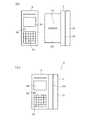
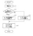
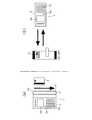
図1(a),(b)は本発明に係るデータ入力兼用カード発行制御装置の外観を示す平面図、図2は同データ入力兼用カード発行制御装置の電気的構成を示す図、図3は同データ入力兼用カード発行制御装置の動作フローチャート、図4(a),(b)は同データ入力兼用カード発行制御装置の使用例を示す説明図である。 1 (a) and 1 (b) are plan views showing the external appearance of the data input / use card issuing control apparatus according to the present invention, FIG. 2 is a diagram showing the electrical configuration of the data input / use card issuing control apparatus, and FIG. FIG. 4A and FIG. 4B are explanatory diagrams showing a usage example of the data input / card issuing control device.
本例のデータ入力兼用カード発行制御装置1は、図1に示すように、ベース部2と操作部3を備えて概略構成され、各種情報が記憶されたカードを利用して例えばホテルの客室等の施設の扉の施解錠を管理するカードロックシステムに採用される。 As shown in FIG. 1, the data input / card issuing control device 1 of this example is schematically configured to include a
本例のデータ入力兼用カード発行制御装置1は、操作部3単体、またはベース部2と操作部3のセットで使用され、ベース部2単体では機能しないように構成されている。 The data input / card issuing control device 1 of this example is configured to be used as a
ベース部2は、操作部3とセットで使用した際に、操作部3からの各種情報(例えばチェックイン/アウトの日時、ホテルコード、客室番号、顧客情報など)の入力により客に手渡すカードを発行している。 When the
ベース部2は、図2に示すように、電源部2a、データ読書部2b、コネクタ部2cを備えている。ベース部2は、図1に示すように、操作部3が着脱される板状の取付部2dの側部に矩形状のデータ読書部2bが配置されている。 As shown in FIG. 2, the
電源部2aは、データ読書部2bに必要な駆動電源を供給している。また、電源部2aは、ベース部2に操作部3がコネクタ接続された状態で、コネクタ部2cを介して操作部3に必要な駆動電源を供給している。 The
データ読書部2bは、電源部2aから電源供給を受けて駆動する例えばスワイプ式の磁気カードリーダー/ライターで構成される。このスワイプ式の磁気カードリーダー/ライターは、手動スワイプ式のため、図1に示すように、発行するカード(磁気カード)4をスライドさせるための長溝からなるスリット2eが本体2fに形成されている。また、手動により磁気カード4をスリット2e内でスライドさせた際、磁気カード4の磁気面に位置して磁気ヘッドが内蔵されている。スワイプ式の磁気カードリーダー/ライターでは、ホテル従業員が操作部3を操作し、例えばチェックイン/アウトの日時、ホテルコード、客室番号、顧客情報などの各種情報を設定入力した後、手動により磁気カード4をスリット2e内でスライドさせると、磁気カード4の磁気面に各種情報を書き込み、チェックイン時に客に手渡されるカード(磁気カード)4を発行している。 The
操作部3は、カードを発行する際の例えばチェックイン/アウトの日時、ホテルコード、客室番号、顧客情報などの各種情報の入力の他、カードロック5へのデータ(電気錠の解錠許可情報:例えばホテルコード、客室番号など)登録や履歴(入退室時間など)吸い上げを行うものである。 The
操作部3は、図2に示すように、電源スイッチ3a、充電池3b、入力部3c、制御部(CPU)3d、表示部3e、コネクタ部3fを備えている。この操作部3は、図1に示すように、ベース部2に一体化させて使用する際に、ベース部2の取付部2dにコネクタ接続される。 As shown in FIG. 2, the
電源スイッチ3aは、操作部3を使用する際に、ユーザーの手動操作によりスイッチをONすることにより充電池3bから各部に必要な駆動電源が供給される。 When the
充電池3bは、電源スイッチ3aがONし、操作部3がベース部2に接続された状態で、ベース部2の電源部2aからコネクタ部2c,3fを介して入力される電源を充電しており、各部に必要な駆動電源を供給している。 The
入力部3cは、テンキーや各種入力キーを備えており、ユーザーのキー操作によりカード発行、各客室のカードロック5へのデータ登録(電気錠の解錠許可情報)や履歴の吸い上げを行う際の各種入力情報が入力される。 The
制御部3dは、CPUおよびROM,RAMなどで構成され、入力部3cからの入力情報の記憶、入力情報に応じて表示部3eの表示制御を行う他、操作部3がベース部2にコネクタ接続された状態で、入力情報をコネクタ部3fを介してベース部2に出力している。また、制御部3cは、操作部3がベース部2にコネクタ接続された状態で、ベース部2の電源部2aからの電源信号(接続信号)の有無に応じてベース部2と操作部3の接続状態を判別し、この接続状態の判別結果に基づいてカード発行制御機モード又はデータ入力機モードとしてソフトを起動している。さらに、制御部3dは、データ入力機モード時にカードロック5から吸い上げた情報を記憶している。 The
表示部3eは、例えば液晶表示装置などで構成され、制御部3dの制御により入力部3cからの入力情報に応じてカード発行制御機モード又はデータ入力機モードを実行するための各種表示を行っている。 The
コネクタ部3fは、操作部3をベース部2に一体化させて使用する際に、ベース部2のコネクタ部2cに電気的に接続される。本例では、操作部3の背面の略中央にコネクタ部3fが設けられ、カード発行制御機モード時にベース部2の取付部2dに設けられたコネクタ部2cに接続される。 The
上記のように構成されるデータ入力兼用カード発行制御装置1の動作について図3および図4を参照しながら説明する。操作部3の電源スイッチ3aがオンすると(ST1)、操作部3の制御部3dがベース部2からの接続信号の有無(電源部2aからの電源供給の有無)を判別する(ST2)。操作部3の制御部3dは、操作部3がベース部2にコネクタ接続されていて、ベース部2から接続信号有り(電源供給有り)と判断すると(ST2−Yes)、カード発行制御機モードとしてソフトを起動する(ST3)。その後、カード発行制御機モードとしてユーザーによるオペレーションが開始される(ST4)。カード発行制御機モードは、ベース部2と操作部3をセットで使用してカードの発行を行うモードである。このカード発行制御機モードでは、図4(a)に示すように、べース部2に操作部3をコネクタ接続した状態で、操作部3から各種情報を入力し、データ読書部2bであるスワイプ式の磁気カードリーダー/ライターに発行前の磁気カード4をスワイプさせて磁気カード4に各種情報を書き込む。これにより、チェックインを済ませた客に手渡されるカードが発行される。 The operation of the data input / issue card issuing control apparatus 1 configured as described above will be described with reference to FIGS. When the
これに対し、操作部3の制御部3dは、例えばベース部2に対して操作部3が未接続またはコネクタ接続が不完全であって、ベース部2から接続信号無し(電源供給無し)と判断すると(ST2−No)、データ入力機モードとしてソフトを起動する(ST5)。その後、データ入力機モードとしてユーザーによるオペレーションが開始される(ST4)。データ入力機モードは、操作部3単体で各客室のカードロック5へのデータ登録(電気錠の解錠許可情報)や履歴の吸い上げを行うモードである。このデータ入力機モードでは、図4(b)に示すように、ベース部2から操作部3を取り外して操作部3のみを単体で用い、操作部3の表示部3eの表示画面の指示に従って入力部3cをキー操作する。 On the other hand, the
このように、本例のデータ入力兼用カード発行制御装置1では、データ読書部2bを実装したベース部2に対し、入力部3cや表示部3eを備えた操作部3が着脱可能にコネクタ接続される構成となっている。そして、操作部3の制御部3dがベース部2からの接続信号(電源部2aからの電源信号)の有無に応じてベース部2と操作部3の接続状態を判別し、この接続状態の判別結果に基づいてカード発行制御機モード又はデータ入力機モードとしてソフトが起動するようになっている。 As described above, in the data input / card issuing control device 1 of this example, the
そして、カード発行を行う場合には、べース部2に操作部3をコネクタ接続すれば、操作部3がベース部2との接続を認識し、カード発行制御機モードとしてソフトが起動する。この状態で、操作部3から各種情報を入力し、データ読書部2bであるスワイプ式の磁気カードリーダー/ライターに発行前の磁気カード4をスワイプさせてカードに各種情報を書き込む。これに対し、各客室のカードロック5へのデータ登録(電気錠の解錠許可情報)や履歴の吸い上げを行う場合には、操作部3をベース部2から取り外す。これにより、操作部3がベース部2との未接続を認識し、データ入力機モードとしてソフトが起動する。この状態で、操作部3の表示部3eの表示画面の指示に従って入力部3cのキー操作を行う。 When the card is issued, if the
このように、本例のデータ入力兼用カード発行制御装置1によれば、カードの発行や各客室のカードロック5へのデータ登録(電気錠の解錠許可情報)や履歴の吸い上げを1台で行うことができる。しかも、操作部3がベース部2に対してコネクタ接続により極めて簡単に着脱できるので、カード発行を行う場合には、ベース部2に操作部3をコネクタ接続し一体化させた状態でフロントなどに設置しておき、操作部3のみを使用して客室のカードロック5へのデータ登録(電気錠の解錠許可情報)や履歴の吸い上げを行う際には、ベース部2から操作部3のみを分離させて容易に持ち運びが行え、用途に応じて使い分けることができる。また、ベース部2の電源部2aからの電源信号の有無によってベース部2と操作部3の電気的接続を操作部3側で判別しているので、ベース部2を電源部2aとデータ読書部2bのみで構成でき、回路構成を簡素化することができる。 As described above, according to the data input / card issuing control device 1 of this example, the card issuance, the data registration to the card lock 5 of each guest room (unlocking permission information of the electric lock), and the siphoning of the history are performed with one unit. It can be carried out. Moreover, since the
ところで、上述した実施の形態では、操作部3がコネクタ接続されている状態でベース部2から操作部3に出力される接続信号を電源部2aからの電源信号として説明した。これにより、ベース部2の回路構成の簡略化を図り、操作部3の制御部3dの制御によりデータ読書部2bを制御してカードの発行を行っている。しかし、接続信号は上記電源信号に限定されるものではなく、例えばベース部2にもCPUおよびROM,RAM等で構成される制御部を設け、操作部3がコネクタ接続されたときに前記制御部から接続信号を出力する構成としても良い。また、ベース部2に前記制御部を設けた場合には、ベース部2と操作部3のコネクタ接続時に、操作部3の制御部3dから接続信号を出力し、この接続信号に対するベース部2の制御部からの応答信号によってベース部2と操作部3の接続状態を判別することもできる。 In the above-described embodiment, the connection signal output from the
1 データ入力兼用カード発行制御装置
2 ベース部
2a 電源部
2b データ読書部
2c コネクタ部
2d 取付部
2e スリット
2f 本体
3 操作部
3a 電源スイッチ
3b 充電池
3c 入力部
3d 制御部
3e 表示部
3f コネクタ部
4 磁気カード
5 カードロックDESCRIPTION OF SYMBOLS 1 Data input combined card
Claims (2)
Translated fromJapanese前記各種情報を入力する操作部と、
前記操作部がコネクタ接続により着脱可能とされ、前記操作部がコネクタ接続されたときの該操作部からの前記各種情報をカードに書き込んでカードを発行するベース部とを備えており、
前記操作部は、前記ベース部と前記操作部との間の電気的な接続状態を判別し、この電気的な接続状態の判別結果に基づいて前記カードを発行するカード発行制御機モード又はカードロックへのデータ登録や履歴の吸い上げを行うデータ入力機モードとしてソフトが起動することを特徴とするデータ入力兼用カード発行制御装置。In a data input and card issuing control device used for a card lock system that manages locking and unlocking of doors of facilities such as guest rooms using cards in which various information is stored,
An operation unit for inputting the various information;
The operation unit is detachable by connector connection, and includes a base unit that writes the various information from the operation unit when the operation unit is connected to the card and issues a card.
The operation unit is configured to determine an electrical connection state between the base unit and the operation unit, and to issue a card based on a determination result of the electrical connection state. A data input / card issuance control device, characterized in that the software is started as a data input machine mode for registering data to the server and collecting history data.
前記操作部は、前記電源部からの電源信号の有無によって前記ベース部と前記操作部との間の電気的な接続状態を判別することを特徴とする請求項1記載のデータ入力兼用カード発行制御装置。The base part includes a power supply part,
2. The data input and card issuing control according to claim 1, wherein the operation unit determines an electrical connection state between the base unit and the operation unit based on the presence or absence of a power signal from the power supply unit. apparatus.
Priority Applications (1)
| Application Number | Priority Date | Filing Date | Title |
|---|---|---|---|
| JP2004049704AJP2005242550A (en) | 2004-02-25 | 2004-02-25 | Card issuing and control device serving as data entry device |
Applications Claiming Priority (1)
| Application Number | Priority Date | Filing Date | Title |
|---|---|---|---|
| JP2004049704AJP2005242550A (en) | 2004-02-25 | 2004-02-25 | Card issuing and control device serving as data entry device |
Publications (1)
| Publication Number | Publication Date |
|---|---|
| JP2005242550Atrue JP2005242550A (en) | 2005-09-08 |
Family
ID=35024249
Family Applications (1)
| Application Number | Title | Priority Date | Filing Date |
|---|---|---|---|
| JP2004049704APendingJP2005242550A (en) | 2004-02-25 | 2004-02-25 | Card issuing and control device serving as data entry device |
Country Status (1)
| Country | Link |
|---|---|
| JP (1) | JP2005242550A (en) |
Cited By (20)
| Publication number | Priority date | Publication date | Assignee | Title |
|---|---|---|---|---|
| JP2008101377A (en)* | 2006-10-18 | 2008-05-01 | Miwa Lock Co Ltd | Card locking system |
| US9195454B2 (en) | 2013-11-27 | 2015-11-24 | Square, Inc. | Firmware management |
| US9224142B2 (en) | 2002-02-05 | 2015-12-29 | Square, Inc. | Card reader with power efficient architecture that includes a power supply and a wake up circuit |
| US9230143B2 (en) | 2013-12-11 | 2016-01-05 | Square, Inc. | Bidirectional audio communication in reader devices |
| US9256769B1 (en) | 2014-02-25 | 2016-02-09 | Square, Inc. | Mobile reader device |
| US9256770B1 (en) | 2014-07-02 | 2016-02-09 | Square, Inc. | Terminal case with integrated reader and shortened base |
| US9262777B2 (en) | 2002-02-05 | 2016-02-16 | Square, Inc. | Card reader with power efficient architecture that includes a wake-up circuit |
| US9262757B2 (en) | 2002-02-05 | 2016-02-16 | Square, Inc. | Method of transmitting information from a card reader with a power supply and wake-up circuit to a mobile device |
| US9286635B2 (en) | 2002-02-05 | 2016-03-15 | Square, Inc. | Method of transmitting information from efficient communication protocol card readers to mobile devices |
| US9305314B2 (en) | 2002-02-05 | 2016-04-05 | Square, Inc. | Methods of transmitting information to mobile devices using cost effective card readers |
| US9355285B1 (en) | 2015-02-12 | 2016-05-31 | Square, Inc. | Tone-based wake up circuit for card reader |
| USD762651S1 (en) | 2014-06-06 | 2016-08-02 | Square, Inc. | Mobile device case |
| US9495676B2 (en) | 2002-02-05 | 2016-11-15 | Square, Inc. | Method of transmitting information from a power efficient card to a mobile device |
| US9576159B1 (en) | 2011-01-24 | 2017-02-21 | Square, Inc. | Multiple payment card reader system |
| US9633236B1 (en) | 2013-12-11 | 2017-04-25 | Square, Inc. | Power harvesting in reader devices |
| US9760740B1 (en) | 2014-06-23 | 2017-09-12 | Square, Inc. | Terminal case with integrated dual reader stack |
| US9799025B2 (en) | 2014-08-19 | 2017-10-24 | Square, Inc. | Energy harvesting bidirectional audio interface |
| US10304043B1 (en) | 2014-05-21 | 2019-05-28 | Square, Inc. | Multi-peripheral host device |
| US10410021B1 (en) | 2017-12-08 | 2019-09-10 | Square, Inc. | Transaction object reader with digital signal input/output and internal audio-based communication |
| US11087301B1 (en) | 2017-12-19 | 2021-08-10 | Square, Inc. | Tamper resistant device |
Citations (2)
| Publication number | Priority date | Publication date | Assignee | Title |
|---|---|---|---|---|
| JPS62119668A (en)* | 1985-11-20 | 1987-05-30 | Matsushita Electric Works Ltd | Card processing system |
| JPH01192969A (en)* | 1988-01-29 | 1989-08-03 | Kokusan Kinzoku Kogyo Co Ltd | Ten key type electric locking system and recitable number generator used for system concerned and ten key type electric locking device |
- 2004
- 2004-02-25JPJP2004049704Apatent/JP2005242550A/enactivePending
Patent Citations (2)
| Publication number | Priority date | Publication date | Assignee | Title |
|---|---|---|---|---|
| JPS62119668A (en)* | 1985-11-20 | 1987-05-30 | Matsushita Electric Works Ltd | Card processing system |
| JPH01192969A (en)* | 1988-01-29 | 1989-08-03 | Kokusan Kinzoku Kogyo Co Ltd | Ten key type electric locking system and recitable number generator used for system concerned and ten key type electric locking device |
Cited By (29)
| Publication number | Priority date | Publication date | Assignee | Title |
|---|---|---|---|---|
| US9495676B2 (en) | 2002-02-05 | 2016-11-15 | Square, Inc. | Method of transmitting information from a power efficient card to a mobile device |
| US10007813B2 (en) | 2002-02-05 | 2018-06-26 | Square, Inc. | Card reader with passive ID circuit |
| US9224142B2 (en) | 2002-02-05 | 2015-12-29 | Square, Inc. | Card reader with power efficient architecture that includes a power supply and a wake up circuit |
| US10140481B2 (en) | 2002-02-05 | 2018-11-27 | Square, Inc. | Card reader with power efficient architecture that includes a power supply and a wake-up circuit |
| US9595033B2 (en) | 2002-02-05 | 2017-03-14 | Square, Inc. | Method of transmitting information from efficient communication protocol card |
| US9858603B2 (en) | 2002-02-05 | 2018-01-02 | Square, Inc. | Card reader with power efficient architecture that includes a wake-up circuit |
| US9262777B2 (en) | 2002-02-05 | 2016-02-16 | Square, Inc. | Card reader with power efficient architecture that includes a wake-up circuit |
| US9262757B2 (en) | 2002-02-05 | 2016-02-16 | Square, Inc. | Method of transmitting information from a card reader with a power supply and wake-up circuit to a mobile device |
| US9286635B2 (en) | 2002-02-05 | 2016-03-15 | Square, Inc. | Method of transmitting information from efficient communication protocol card readers to mobile devices |
| US9305314B2 (en) | 2002-02-05 | 2016-04-05 | Square, Inc. | Methods of transmitting information to mobile devices using cost effective card readers |
| US9449203B2 (en) | 2002-02-05 | 2016-09-20 | Square, Inc. | Card reader with power efficient architecture that includes a power supply and a wake-up circuit |
| JP2008101377A (en)* | 2006-10-18 | 2008-05-01 | Miwa Lock Co Ltd | Card locking system |
| US9576159B1 (en) | 2011-01-24 | 2017-02-21 | Square, Inc. | Multiple payment card reader system |
| US9195454B2 (en) | 2013-11-27 | 2015-11-24 | Square, Inc. | Firmware management |
| US9230143B2 (en) | 2013-12-11 | 2016-01-05 | Square, Inc. | Bidirectional audio communication in reader devices |
| US9633236B1 (en) | 2013-12-11 | 2017-04-25 | Square, Inc. | Power harvesting in reader devices |
| US9460322B2 (en) | 2014-02-25 | 2016-10-04 | Square, Inc. | Mobile reader device |
| US9256769B1 (en) | 2014-02-25 | 2016-02-09 | Square, Inc. | Mobile reader device |
| US10304043B1 (en) | 2014-05-21 | 2019-05-28 | Square, Inc. | Multi-peripheral host device |
| USD762651S1 (en) | 2014-06-06 | 2016-08-02 | Square, Inc. | Mobile device case |
| US9760740B1 (en) | 2014-06-23 | 2017-09-12 | Square, Inc. | Terminal case with integrated dual reader stack |
| US10579836B1 (en) | 2014-06-23 | 2020-03-03 | Square, Inc. | Displaceable card reader circuitry |
| US9256770B1 (en) | 2014-07-02 | 2016-02-09 | Square, Inc. | Terminal case with integrated reader and shortened base |
| US9799025B2 (en) | 2014-08-19 | 2017-10-24 | Square, Inc. | Energy harvesting bidirectional audio interface |
| US9659195B2 (en) | 2015-02-12 | 2017-05-23 | Square, Inc. | Tone-based wake up circuit for card reader |
| US9355285B1 (en) | 2015-02-12 | 2016-05-31 | Square, Inc. | Tone-based wake up circuit for card reader |
| US10410021B1 (en) | 2017-12-08 | 2019-09-10 | Square, Inc. | Transaction object reader with digital signal input/output and internal audio-based communication |
| US11100298B1 (en) | 2017-12-08 | 2021-08-24 | Square, Inc. | Transaction object reader with analog and digital signal interface |
| US11087301B1 (en) | 2017-12-19 | 2021-08-10 | Square, Inc. | Tamper resistant device |
Similar Documents
| Publication | Publication Date | Title |
|---|---|---|
| JP2005242550A (en) | Card issuing and control device serving as data entry device | |
| JP2007040092A (en) | Auxiliary system for locking, and auxiliary equipment for lock | |
| KR20130138878A (en) | Automatic administration system for guest room of accomodation | |
| JP2007004478A (en) | Personal identification system | |
| JPH06119525A (en) | Method for managing automatic teller machine | |
| JP2003159466A (en) | Gaming-related equipment monitoring device, gaming-related equipment and amusement arcade monitoring system | |
| JP2002245505A (en) | Apparatus and system for processing front business data | |
| JP2007025825A (en) | Automatic transaction apparatus, transaction approval method using the same, and transaction approval program for automatic transaction apparatus | |
| KR20010094329A (en) | service system of uninhabited a guest room | |
| JP5243321B2 (en) | Card lock system | |
| JP2007218049A (en) | Key and cash depositor/dispenser locked or unlocked by the key | |
| JP3955857B2 (en) | Shoe locker and undressing locker management system | |
| JP2774888B2 (en) | Door lock device for key management machine | |
| JP2573858Y2 (en) | Rocker equipment | |
| JP5124222B2 (en) | Locker system | |
| JP2006265858A (en) | Card lock system for hotel | |
| JP2007205132A (en) | Card lock system | |
| CN2479146Y (en) | Fingerprint and IC card lock | |
| JP2007197924A (en) | Card lock system | |
| JP2006155425A (en) | Commuter ticket issuing device and card processing device | |
| JPH03202997A (en) | Amusement facilities control system | |
| KR101953026B1 (en) | Automatic ticket office machine with touch screen input type | |
| JP3061731U (en) | Ticketing unit for valuable cards with pictures | |
| JP2008090336A (en) | Image output system, server, image output apparatus, and program | |
| JP2002136743A (en) | Key unit, unit controller and playground key system |
Legal Events
| Date | Code | Title | Description |
|---|---|---|---|
| A621 | Written request for application examination | Free format text:JAPANESE INTERMEDIATE CODE: A621 Effective date:20070124 | |
| A131 | Notification of reasons for refusal | Free format text:JAPANESE INTERMEDIATE CODE: A131 Effective date:20090728 | |
| A521 | Written amendment | Free format text:JAPANESE INTERMEDIATE CODE: A523 Effective date:20090918 | |
| A131 | Notification of reasons for refusal | Free format text:JAPANESE INTERMEDIATE CODE: A131 Effective date:20091208 | |
| A521 | Written amendment | Free format text:JAPANESE INTERMEDIATE CODE: A523 Effective date:20100128 | |
| A02 | Decision of refusal | Free format text:JAPANESE INTERMEDIATE CODE: A02 Effective date:20100608 |