JP2005239440A - Nitride semiconductor substrate, semiconductor device, semiconductor light emitting element, and semiconductor light receiving element - Google Patents
Nitride semiconductor substrate, semiconductor device, semiconductor light emitting element, and semiconductor light receiving elementDownload PDFInfo
- Publication number
- JP2005239440A JP2005239440AJP2004047612AJP2004047612AJP2005239440AJP 2005239440 AJP2005239440 AJP 2005239440AJP 2004047612 AJP2004047612 AJP 2004047612AJP 2004047612 AJP2004047612 AJP 2004047612AJP 2005239440 AJP2005239440 AJP 2005239440A
- Authority
- JP
- Japan
- Prior art keywords
- layer
- semiconductor layer
- semiconductor
- seed crystal
- semiconductor substrate
- Prior art date
- Legal status (The legal status is an assumption and is not a legal conclusion. Google has not performed a legal analysis and makes no representation as to the accuracy of the status listed.)
- Granted
Links
- 239000004065semiconductorSubstances0.000titleclaimsabstractdescription359
- 239000000758substrateSubstances0.000titleclaimsabstractdescription94
- 150000004767nitridesChemical class0.000titleclaimsabstractdescription67
- 238000005253claddingMethods0.000claimsabstractdescription21
- 239000013078crystalSubstances0.000claimsdescription151
- 230000000737periodic effectEffects0.000claimsdescription27
- 229910052594sapphireInorganic materials0.000claimsdescription15
- 239000010980sapphireSubstances0.000claimsdescription15
- 238000000034methodMethods0.000claimsdescription13
- HBMJWWWQQXIZIP-UHFFFAOYSA-Nsilicon carbideChemical compound[Si+]#[C-]HBMJWWWQQXIZIP-UHFFFAOYSA-N0.000claimsdescription6
- 229910010271silicon carbideInorganic materials0.000claimsdescription6
- 229910007946ZrBInorganic materials0.000claimsdescription3
- 229910052710siliconInorganic materials0.000claimsdescription3
- 239000010703siliconSubstances0.000claimsdescription3
- 238000004519manufacturing processMethods0.000abstractdescription16
- 238000005336crackingMethods0.000abstract1
- 230000031700light absorptionEffects0.000description11
- 230000000694effectsEffects0.000description10
- 238000000151depositionMethods0.000description9
- 230000008021depositionEffects0.000description9
- 230000000644propagated effectEffects0.000description5
- 230000006798recombinationEffects0.000description5
- 238000005215recombinationMethods0.000description5
- 239000010409thin filmSubstances0.000description5
- 229910002704AlGaNInorganic materials0.000description4
- 230000015556catabolic processEffects0.000description4
- 239000000203mixtureSubstances0.000description4
- 238000001947vapour-phase growthMethods0.000description4
- 239000000463materialSubstances0.000description3
- 150000002902organometallic compoundsChemical class0.000description3
- 229910021486amorphous silicon dioxideInorganic materials0.000description2
- 238000005530etchingMethods0.000description2
- 239000010408filmSubstances0.000description2
- 229910052751metalInorganic materials0.000description2
- 239000002184metalSubstances0.000description2
- 150000002736metal compoundsChemical class0.000description2
- 238000002360preparation methodMethods0.000description2
- GWEVSGVZZGPLCZ-UHFFFAOYSA-NTitan oxideChemical compoundO=[Ti]=OGWEVSGVZZGPLCZ-UHFFFAOYSA-N0.000description1
- 238000010521absorption reactionMethods0.000description1
- 230000004888barrier functionEffects0.000description1
- 239000012141concentrateSubstances0.000description1
- 230000007547defectEffects0.000description1
- 238000005286illuminationMethods0.000description1
- 239000004973liquid crystal related substanceSubstances0.000description1
- 239000005416organic matterSubstances0.000description1
- 230000000149penetrating effectEffects0.000description1
- 239000011941photocatalystSubstances0.000description1
- 238000001556precipitationMethods0.000description1
- 230000001902propagating effectEffects0.000description1
- 238000000992sputter etchingMethods0.000description1
- OGIDPMRJRNCKJF-UHFFFAOYSA-Ntitanium oxideInorganic materials[Ti]=OOGIDPMRJRNCKJF-UHFFFAOYSA-N0.000description1
- 238000007740vapor depositionMethods0.000description1
Images


Landscapes
- Crystals, And After-Treatments Of Crystals (AREA)
- Led Devices (AREA)
- Light Receiving Elements (AREA)
Abstract
Translated fromJapaneseDescription
Translated fromJapanese本発明は、窒化物半導体基板、半導体デバイス、半導体発光素子および半導体受光素子に関する。 The present invention relates to a nitride semiconductor substrate, a semiconductor device, a semiconductor light emitting element, and a semiconductor light receiving element.
従来、この種の窒化物半導体基板として、図8に示すような窒化物半導体基板1が提案されている(例えば、特許文献1、参照。)。窒化物半導体基板1において、周期ストライプ状に起伏するAlGaNからなるシード結晶層8上に、AlNからなる低温堆積中間層5を形成し、さらに同低温堆積中間層5上にAlGaNからなる半導体層6を形成している。 Conventionally, a nitride semiconductor substrate 1 as shown in FIG. 8 has been proposed as this type of nitride semiconductor substrate (see, for example, Patent Document 1). In the nitride semiconductor substrate 1, a low temperature deposition
かかる構成によれば、低温堆積中間層5が互いに格子定数の異なるシード結晶層8と半導体層6との間に介在するため、シード結晶層8と半導体層6との間の格子不整合に起因する内部応力を緩和することが可能であった。すなわち、この内部応力によって、半導体層6においてクラックが発生することを抑制することが可能であった。このように、半導体層6に発生するクラックを抑制することにより、最終的には半導体層6の平坦表面が得ることができる。従って、各種半導体発光素子や半導体受光素子の作製に好適な窒化物半導体基板を得ることが可能となっていた。 According to such a configuration, since the low temperature deposition
一方、同窒化物半導体基板においてシード結晶層8は周期ストライプ状に起伏し面方位が(1−101)である斜面を有している。このようにすることにより、半導体層6の成長において成長方向に貫通する転位Dの伝播を横方向とすることができる。従って、半導体層6においてはシード結晶層8の各起伏部の中央位置に転位を集中させることができ、極めて転位の少ない半導体層6表面を得ることができる。 On the other hand, in the nitride semiconductor substrate, the seed crystal layer 8 has an inclined surface having a periodic stripe shape and a plane orientation of (1-101). By doing so, the propagation of dislocations D penetrating in the growth direction in the growth of the semiconductor layer 6 can be set in the lateral direction. Therefore, in the semiconductor layer 6, dislocations can be concentrated at the center position of each undulation portion of the seed crystal layer 8, and the surface of the semiconductor layer 6 with very few dislocations can be obtained.
このように極めて転位の少ない半導体層6表面上に半導体発光素子を作製すると非発光再結合を抑制することができるため、同半導体発光素子においては高い量子効率を得ることが可能であった。従って、発光効率の良い半導体発光素子を作製することが可能であった。また、同様の理由により、半導体層6表面上に半導体受光素子を形成することによって、高耐圧、低暗電流性の優れた半導体受光素子を作製することが可能であった。
しかしながら、上述した窒化物半導体基板において、応力緩和効果が良好な低温堆積中間層5を形成するためにはその成長温度を500〜600℃に制御しなければならず、高度の温度制御が要求されるという課題があった。なお、500℃以下の温度で低温堆積中間層5を成長させると半導体層6の結晶品質が低下し、600℃以上の温度で低温堆積中間層5を成長させると低温堆積中間層5の格子不整合緩和効果が低下する。 However, in the nitride semiconductor substrate described above, in order to form the low temperature deposition
さらに、半導体層6におけるAlNモル分率が20%を超える場合には半導体層6とシード結晶層8との格子不整合が著しいものとなり、低温堆積中間層5の応力緩和効果が良好なものであっても半導体層6におけるクラックを抑制することができないという課題があった。すなわち、AlNモル分率が20%を超えるような半導体層6を形成することができないという課題があった。 Furthermore, when the AlN molar fraction in the semiconductor layer 6 exceeds 20%, the lattice mismatch between the semiconductor layer 6 and the seed crystal layer 8 becomes significant, and the stress relaxation effect of the low temperature deposition
一方、半導体層6のAlNモル分率が20%よりも高く、かつ、半導体層6の表面にクラックのない窒化物半導体基板が作製できると、同半導体層6の表面上にAlNモル分率の高い半導体構造を形成することが可能となる。半導体層6のAlNモル分率が高ければ、その上に形成するAlNモル分率の高い半導体構造との構成整合性が良くなり、クラックが発生することを防止できるからである。また、クラックを発生させることなくAlNモル分率の高い半導体構造の膜厚を大きくすることも可能となる。 On the other hand, when a nitride semiconductor substrate having an AlN mole fraction of the semiconductor layer 6 higher than 20% and having no cracks on the surface of the semiconductor layer 6 can be produced, the AlN mole fraction on the surface of the semiconductor layer 6 is increased. A high semiconductor structure can be formed. This is because if the AlN mole fraction of the semiconductor layer 6 is high, the structural consistency with the semiconductor structure having a high AlN mole fraction formed thereon is improved, and the occurrence of cracks can be prevented. It is also possible to increase the film thickness of a semiconductor structure having a high AlN molar fraction without generating cracks.
AlNモル分率の高い半導体構造はワイドギャップを有しているため、近年、AlNモル分率の高い半導体構造がクラックフリーで積層可能な窒化物半導体の実現が望まれている。例えば、窒化物半導体基板上にAlNモル分率の高いAlGaNクラッド層を積層した場合、波長が340〜350nm程度の深紫外線領域の短波長光も発光させることが可能な半導体発光素子を作製することも可能となる。このような短波長光の発光が実現すると、外部光源によって色味が変動しない白色照明や液晶パネルのバックライト等の作製や、酸化チタン等の光触媒を励起させて有機物を分解するための光源を作製することが可能となる。また、AlGaNクラッド層の膜厚を大きくすることができるため、同クラッド層にて光の閉じ込めを行うことが可能となり半導体レーザの作製に利用することも可能となる。 Since a semiconductor structure having a high AlN mole fraction has a wide gap, in recent years, it has been desired to realize a nitride semiconductor in which a semiconductor structure having a high AlN mole fraction can be stacked without cracks. For example, when an AlGaN cladding layer having a high AlN mole fraction is stacked on a nitride semiconductor substrate, a semiconductor light emitting device capable of emitting short wavelength light in the deep ultraviolet region having a wavelength of about 340 to 350 nm is manufactured. Is also possible. When such short-wavelength light emission is realized, it is possible to produce a white illumination that does not vary in color by an external light source, a backlight of a liquid crystal panel, etc., or a light source for decomposing organic matter by exciting a photocatalyst such as titanium oxide. It can be produced. Further, since the thickness of the AlGaN cladding layer can be increased, light can be confined in the cladding layer and can be used for manufacturing a semiconductor laser.
また、このような窒化物半導体基板を半導体受光素子の作製に利用すると、AlNモル分率の高いワイドギャップ光吸収層を形成することが可能となり、波長が300nm以下の短波長領域でも動作可能な半導体受光素子を作製することが可能となる。このように、AlNモル分率の高い半導体構造がクラックフリーで積層可能な窒化物半導体の実現は、今後の半導体発光・半導体受光素子の作製において極めて重要な課題となっている。 In addition, when such a nitride semiconductor substrate is used for manufacturing a semiconductor light receiving element, it is possible to form a wide gap light absorption layer with a high AlN molar fraction, and it is possible to operate even in a short wavelength region with a wavelength of 300 nm or less. A semiconductor light receiving element can be manufactured. Thus, the realization of a nitride semiconductor in which a semiconductor structure having a high AlN mole fraction can be stacked without cracks is an extremely important issue in the production of future semiconductor light emitting and semiconductor light receiving elements.
本発明は、上記課題にかんがみてなされたもので、作製が容易、かつ、AlNモル分率の高い半導体構造がクラックフリーで積層可能な窒化物半導体、および、同窒化物半導体を利用した半導体デバイス、半導体発光素子および半導体受光素子の提供を目的とする。 SUMMARY OF THE INVENTION The present invention has been made in view of the above problems, and is a nitride semiconductor that can be easily manufactured and can be stacked with a high AlN molar fraction in a crack-free manner, and a semiconductor device using the nitride semiconductor An object of the present invention is to provide a semiconductor light emitting device and a semiconductor light receiving device.
上記目的を達成するため請求項1にかかる発明は、AlxGa1-x-yInyN(0≦x≦0.3,0≦y≦0.5)から成るシード結晶層と、上記シード結晶層上に形成され(0001)面 AlaGa1-a-bInbN(0.1≦a≦1,0≦b≦1)からなる半導体層とを備えるとともに、上記半導体層の内部には、同半導体層の内部にて同半導体層の表面側が終端する隙間が備えられる構成としてある。In order to achieve the above object, the invention according to claim 1 includes a seed crystal layer made of Alx Ga1 -xy Iny N (0 ≦ x ≦ 0.3, 0 ≦ y ≦ 0.5), and the seed crystal. Anda semiconductor layer made of (0001) plane Ala Ga1-ab Inb N (0.1 ≦ a ≦ 1, 0 ≦ b ≦ 1), and the inside of the semiconductor layer, In the semiconductor layer, a gap is provided that terminates on the surface side of the semiconductor layer.
上記のように構成した請求項1の発明において、シード結晶層はAlxGa1-x-yInyN(0≦x≦0.3,0≦y≦0.5)から構成され、同シード結晶層上に半導体層が形成される。この半導体層は、(0001)面 AlaGa1-a-bInbN(0.1≦a≦1,0≦b≦1)で構成されるとともに、内部に隙間を備える。上記隙間は上記半導体層の内部にて表面側が終端する。すなわち、上記隙間は上記半導体層の表面まで到達しない。従って、上記半導体層の表面を平坦に形成することができる。また、上記半導体層内部に蓄積された内部応力を上記隙間により緩和することができる。従って、内部応力によりクラックが発生することを防止することができる。In the invention of claim 1 configured as described above, the seed crystal layer is composed of Alx Ga1 -xy Iny N (0 ≦ x ≦ 0.3, 0 ≦ y ≦ 0.5). A semiconductor layer is formed on the layer. This semiconductor layer is composed of (0001) plane Ala Ga1-ab Inb N (0.1 ≦ a ≦ 1, 0 ≦ b ≦ 1) and has a gap inside. The gap ends at the surface side inside the semiconductor layer. That is, the gap does not reach the surface of the semiconductor layer. Therefore, the surface of the semiconductor layer can be formed flat. Also, the internal stress accumulated in the semiconductor layer can be relaxed by the gap. Therefore, it is possible to prevent cracks from being generated due to internal stress.
さらに、上記隙間の一態様として、請求項2にかかる発明は、上記隙間は、上記半導体層の表面側が終端させられたクラックである構成としてある。
上記のように構成した請求項2の発明において、上記半導体層にクラックを発生させ、同クラックを表面側から終端させることにより上記隙間を形成する。例えば、上記半導体層の成長過程において上記クラックを発生させ、その後も継続的に上記半導体層を成長させることにより、上記クラックを終端させることができる。なお、上記クラックを終端させるには、上記クラックの発生後、横方向成長が促進される条件で上記半導体層を成長させることが好ましい。Furthermore, as an aspect of the gap, the invention according to
In the invention of
また、上記クラックを発生させる手法の一例として、請求項3にかかる発明は、上記シード結晶層の格子定数は、上記半導体層の格子定数よりも0.1%以上大きい構成としてある。
上記のように構成した請求項3の発明において、上記シード結晶層の格子定数を上記半導体層の格子定数よりも0.1%以上大きくすることにより、上記クラックを発生しやすくすることができる。すなわち、上記シード結晶層と上記半導体層との間の格子不整合により上記半導体層を引き延ばそうとする内部応力を蓄積させることができるため、同蓄積した内部応力により上記半導体層に上記クラックを発生させることができる。As an example of the method for generating the crack, the invention according to
In the invention of
一方、上記シード結晶層の一例として、請求項4にかかる発明は、上記シード結晶層は周期ストライプ状に起伏する構成としてある。
上記のように構成した請求項4の発明において、上記シード結晶層は周期ストライプ状に起伏させることにより、その上に形成される上記半導体層の転位の伝播方向を横方向とすることができる。すなわち、上記半導体層の内部に生成する転位を同半導体層の表面に到達させにくくするとともに、表面到達転位を各シード結晶層の中央位置に集中させることができる。On the other hand, as an example of the seed crystal layer, the invention according to claim 4 is configured such that the seed crystal layer undulates in a periodic stripe shape.
In the invention of claim 4 configured as described above, the seed crystal layer is undulated in the form of periodic stripes, whereby the dislocation propagation direction of the semiconductor layer formed thereon can be set to the lateral direction. That is, it is possible to make it difficult for dislocations generated in the semiconductor layer to reach the surface of the semiconductor layer, and to concentrate surface dislocations at the center position of each seed crystal layer.
また、上記シード結晶層の具体的形状の一例として、請求項5にかかる発明は、上記シード結晶層の起伏部は上記半導体層の表面に対して傾斜する斜面を有する構成としてある。
上記のように構成した請求項5の発明において、上記シード結晶層の起伏部に上記半導体層の表面に対して傾斜する斜面を形成することにより、上記斜面上に成長する上記半導体層における転位の伝播方向を上記半導体層の表面に対して傾斜させることができる。これによって、転位を上記半導体層の表面に到達させにくくすることができ、上記半導体層の表面における転位密度を低減することができる。As an example of a specific shape of the seed crystal layer, the invention according to
In the invention of
一方、上記シード結晶層の形成手段の一例として、請求項6にかかる発明は、上記シード結晶層は、(0001)面 AlxGa1-x-yInyN(0≦x≦0.3,0≦y≦0.5)からなるベース半導体層上にストライプ状の周期マスクを形成し、その後、AlxGa1-x-yInyN(0≦x≦0.3,0≦y≦0.5)を成長させる構成としてある。On the other hand, as an example of the means for forming the seed crystal layer, the invention according to claim 6 is directed to that the seed crystal layer has a (0001) plane of Alx Ga1 -xy Iny N (0 ≦ x ≦ 0.3, 0). A periodic mask having a stripe shape is formed on the base semiconductor layer made of ≦ y ≦ 0.5, and then Alx Ga1-xy Iny N (0 ≦ x ≦ 0.3, 0 ≦ y ≦ 0.5). ).
上記のように構成した請求項6発明において、(0001)面 AlxGa1-x-yInyN(0≦x≦0.3,0≦y≦0.5)で構成されるベース半導体層を形成しておき、同ベース半導体層上にストライプ状の周期マスクを形成する。そして、このストライプ状の周期マスクが形成された上記ベース半導体層上に(0001)面 AlxGa1-x-yInyN(0≦x≦0.3,0≦y≦0.5)を成長させることにより、上記シード結晶層を形成する。 In the present invention configured as described above, a base semiconductor layer composed of (0001) plane AlxGa1-xyInyN (0≤x≤0.3, 0≤y≤0.5) is formed. A striped periodic mask is formed on the base semiconductor layer. Then, by growing (0001) plane AlxGa1-x-yInyN (0 ≦ x ≦ 0.3, 0 ≦ y ≦ 0.5) on the base semiconductor layer on which the striped periodic mask is formed, The seed crystal layer is formed.
また、上記シード結晶層の形成手段の別の一例として、請求項7にかかる発明は、上記シード結晶層は、周期ストライプ状に起伏する(0001)面 AlxGa1-x-yInyN(0≦x≦0.3,0≦y≦0.5)からなるストライプ半導体層上にAlxGa1-x-yInyN(0≦x≦0.3,0≦y≦0.5)を成長させることにより形成される構成としてある。Further, as another example of the means for forming the seed crystal layer, the invention according to claim 7 is directed to the (0001) plane Alx Ga1 -xy Iny N (0 Alx Ga1-xy Iny N (0 ≦ x ≦ 0.3, 0 ≦ y ≦ 0.5) is grown on the stripe semiconductor layer composed of ≦ x ≦ 0.3 and 0 ≦ y ≦ 0.5) It is as a structure formed by making it.
上記のように構成した請求項7発明において、ストライプ半導体層は周期ストライプ状に起伏するとともに、(0001)面 AlxGa1-x-yInyN(0≦x≦0.3,0≦y≦0.5)で構成される。そして、同ストライプ半導体層上にAlxGa1-x-yInyN(0≦x≦0.3,0≦y≦0.5)を成長させることにより、上記シード結晶層を形成する。According to the seventh aspect of the invention configured as described above, the stripe semiconductor layer undulates in a periodic stripe shape, and (0001) plane Alx Ga1 -xy Iny N (0 ≦ x ≦ 0.3, 0 ≦ y ≦ 0.5). Then, Alx Ga1 -xy Iny N (0 ≦ x ≦ 0.3, 0 ≦ y ≦ 0.5) is grown on the stripe semiconductor layer, thereby forming the seed crystal layer.
また、上記シード結晶層の形成手段の別の一例として、請求項8にかかる発明は、上記シード結晶層は、周期ストライプ状に起伏する単結晶基板にAlxGa1-x-yInyN(0≦x≦0.3,0≦y≦0.5)を成長させることにより形成される構成としてある。
上記のように構成した請求項8発明において、周期ストライプ状に起伏する単結晶基板に対して、AlxGa1-x-yInyN(0≦x≦0.3,0≦y≦0.5)を成長させることによっても周期ストライプ状の上記シード結晶層を形成することもできる。As another example of the means for forming the seed crystal layer, the invention according to claim 8 is characterized in that the seed crystal layer is formed of Alx Ga1-xy Iny N (0 ≦ x ≦ 0.3, 0 ≦ y ≦ 0.5).
In the invention of claim 8 configured as described above, Alx Ga1 -xy Iny N (0 ≦ x ≦ 0.3, 0 ≦ y ≦ 0.5) is applied to the single crystal substrate undulating in a periodic stripe shape. ) Can be grown to form the seed crystal layer in a periodic stripe shape.
また、上記シード結晶層の具体的形状の一例として、請求項9にかかる発明は、上記斜面は、(1−101)面である構成としてある。
上記のように構成した請求項9発明において、上記斜面を(1−101)面とすることにより、上記半導体層における転位の伝播方向を横方向とすることができる。As an example of a specific shape of the seed crystal layer, the invention according to claim 9 is configured such that the slope is a (1-101) plane.
In the ninth aspect of the invention configured as described above, by disposing the inclined surface as a (1-101) plane, the propagation direction of dislocations in the semiconductor layer can be a lateral direction.
さらに、上記シード結晶層の具体的形状の別の一例として、請求項10にかかる発明は、上記斜面は、(11−22)面である構成としてある。
上記のように構成した請求項10発明において、上記斜面を(11−22)面とすることにより、上記半導体層における転位の伝播方向を横方向とすることができる。Furthermore, as another example of the specific shape of the seed crystal layer, the invention according to
In the tenth aspect of the present invention configured as described above, by disposing the inclined surface as a (11-22) plane, the propagation direction of dislocations in the semiconductor layer can be a lateral direction.
一方、上記単結晶基板の素材の例として、請求項11にかかる発明は、上記単結晶基板は、サファイアまたは炭化珪素または珪素またはZrB2で形成される構成としてある。
上記のように構成した請求項11発明において、AlxGa1-x-yInyNの成長に好適な上記単結晶基板の素材としてサファイアまたは炭化珪素または珪素またはZrB2を適用することができる。On the other hand, as an example of the material of the single crystal substrate, the invention according to
In the eleventh aspect of the invention configured as described above, sapphire, silicon carbide, silicon, or ZrB2 can be applied as a material for the single crystal substrate suitable for the growth of Alx Ga1 -xy Iny N.
上述の窒化物半導体基板は単独で存在する場合もあるし、あるデバイスに組み込まれた状態で利用されることもあるなど、発明の思想としては、各種の態様を含むものである。その一例として、請求項12に記載した発明では半導体デバイスとして発明を特定し、請求項13に記載した発明では半導体発光素子として発明を特定し、請求項14に記載した発明では半導体受光素子として発明を特定している。また、一次複製品、二次複製品などの複製段階については全く問う余地無く同等である。さらに、これらの半導体デバイスおよび半導体発光素子および半導体受光素子において上記請求項2〜請求項11に対応した構成にすることも可能である。 The above-described nitride semiconductor substrate may exist alone, or may be used in a state of being incorporated in a certain device. The idea of the invention includes various aspects. As an example, the invention described in
さらに、請求項15にかかる発明は、AlxGa1-x-yInyN(0≦x≦0.3,0≦y≦0.5)から成るシード結晶層と、上記シード結晶層上に形成され(0001)面 AlaGa1-a-bInbN(0.1≦a≦1,0≦b≦1)からなる半導体層とを備えるとともに、上記半導体層の成長過程においてクラックを発生させ、さらに、同半導体層の成長を続行することにより同クラックの少なくとも表面側が消失させられる構成としてある。Furthermore, the invention according to
すなわち、上記半導体層の成長過程においてクラックを発生させることにより、上記半導体層の内部に蓄積した内部応力を一度解放させることができる。従って、最終的には低内部応力状態の上記半導体層を得ることができる。また、少なくとも上記クラックの表面側が消失していれば、各種半導体素子を上記半導体層に問題なく積層することができる。つまり、少なくとも上記クラックの表面側が消失していれば良く、上記クラックの全体が消失していても良い。 That is, by generating a crack in the growth process of the semiconductor layer, the internal stress accumulated in the semiconductor layer can be released once. Therefore, the semiconductor layer having a low internal stress state can be finally obtained. If at least the surface side of the crack has disappeared, various semiconductor elements can be stacked on the semiconductor layer without any problem. That is, it is sufficient that at least the surface side of the crack disappears, and the entire crack may disappear.
以上説明したように請求項1および請求項12から請求項15の発明によれば作製が容易、かつ、AlNモル分率が高く表面にクラックのない半導体層を有する窒化物半導体基板、半導体デバイス、半導体発光素子および半導体受光素子を提供することができる。
請求項2の発明によれば、容易に半導体層中に隙間を形成することができる。
請求項3の発明によれば、容易に半導体層中にクラックを形成することができる。
請求項4、請求項5、請求項9および請求項10の発明によれば、半導体層表面に到達する転位を減少させることができる。
請求項6から請求項8の発明によれば、シード結晶層の具体的形成手段を提供することができる。
請求項11の発明によれば、シード結晶層の成長に好適な単結晶基板の素材を提供することができる。As described above, according to the inventions of claim 1 and claims 12 to 15, a nitride semiconductor substrate, a semiconductor device, which has a semiconductor layer that is easy to manufacture and has a high AlN molar fraction and no cracks on the surface, A semiconductor light emitting element and a semiconductor light receiving element can be provided.
According to invention of
According to invention of
According to the invention of claim 4,
According to the sixth to eighth aspects of the present invention, a specific means for forming the seed crystal layer can be provided.
According to the eleventh aspect of the present invention, it is possible to provide a single crystal substrate material suitable for the growth of the seed crystal layer.
ここでは、下記の順序に従って本発明の実施形態について説明する。
(1)第一の実施形態:
(2)第二の実施形態:
(3)第三の実施形態:
(4)第四の実施形態:
(5)第五の実施形態:Here, embodiments of the present invention will be described in the following order.
(1) First embodiment:
(2) Second embodiment:
(3) Third embodiment:
(4) Fourth embodiment:
(5) Fifth embodiment:
(1)第一の実施形態:
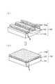
図1は、本発明の第一の実施の形態にかかる低転位3族窒化物半導体基板の構造、および作製方法を模式的に示している。同図(a)において、窒化物半導体基板10は、(0001)サファイアで形成された単結晶基板11と、AlN低温バッファ層12と、GaN(AlxGa1-x-yInyN,x=0,y=0)で形成されたベース半導体層13と、アモルファスSiO2で形成された周期マスク14と、GaN(AlxGa1-x-yInyN,x=0,y=0)で形成されたシード結晶層15と、Al0.25Ga0.75N(AlaGa1-a-bInbN,a=0.25,b=0)で形成された半導体層16とから構成されている。また、半導体層16は内部に隙間17を有している。また、ベース半導体層13とシード結晶層15と半導体層16には線状の転位Dが複数形成されている。(1) First embodiment:
FIG. 1 schematically shows a structure of a
図1(c)において、有機金属化合物気相成長法により単結晶基板11上に約500℃で低温バッファ層12を成長させ、さらに同低温バッファ層12上に約1000℃でベース半導体層13を成長させている。ベース半導体層13には上方に向かって伝播する多数の転位Dが存在しており、ベース半導体層13の表面まで到達している。一般にベース半導体層13の表面まで到達する転位Dの密度は、109cm-2程度にも達する。In FIG. 1C, a low
図1(b)において、上記のように低温バッファ層12とベース半導体層13とを形成した窒化物半導体基板10を一旦成長装置から取り出し、例えば結晶方位<11−20>に沿って幅3μmの周期マスク14を6μm周期で形成する。そして、その上に適切な条件でGaNの選択成長を行うと、結晶方位<11−20>に沿って周期ストライプ状に起伏するシード結晶層15を形成することができる。このシード結晶層15の外縁は、頂点にて交差する二面の(1−101)斜面で構成されている。これにより、シード結晶層15に対して下地のベース半導体層13から伝播した転位Dを、シード結晶層15の内部で略水平方向に屈曲させることができる。ただし、シード結晶層15のAlNモル分率が高いと周期マスク14上への多結晶の析出が顕著となり、好ましくない。そのため、AlNモル分率が10%以下となるようにシード結晶層15を形成するのが好ましい。 In FIG. 1B, the
さらに、図1(a)において上記のように形成した窒化物半導体基板10に対してAl0.25Ga0.75Nを成長させることより、半導体層16を形成している。半導体層16を形成するにあたっては、例えば低成長圧力、高温、低5族−4族比といった横方向への成長速度が上がる条件においてAl0.25Ga0.75Nを成長させている。また、半導体層16を構成するAl0.25Ga0.75Nに対してシード結晶層15を構成するGaNはAlNモル分率が低いため、シード結晶層15の格子定数は半導体層16の格子定数よりも0.1%以上大きくなっている。Further, the
このような格子不整合により、半導体層16に引っ張り方向の内部応力を蓄積させることができる。この内部応力は半導体層16の膜厚の増加とともに増加し、結晶固有の限界値を超えたところで図2に示すようなクラックCを発生させる。同時に、クラックCの発生により、同内部応力を緩和させることができる。そして、クラックCの発生後も横方向への成長速度が上がる条件において半導体層16の結晶成長を継続すると、クラックCの上方開口がAl0.25Ga0.75Nの結晶により再結合される。さらに、半導体層16の結晶成長を継続すると最終的に平坦な半導体層16の表面を形成することができる。Due to such lattice mismatch, internal stress in the tensile direction can be accumulated in the
上述のとおり一度発生したクラックCの上方開口は再結合させられているため、同クラックは半導体層16の表面まで到達しない。すなわち、クラックCを半導体層16の表面側から終端させることにより、クラックCのない半導体層16の平坦表面を得ることができる。一般に、半導体層16の表面までクラックCが到達すると、同半導体層16の表面上に各種半導体構造を積層して高性能デバイスを作製することはできないが、表面までクラックCを到達させないようにすることにより問題なく高性能デバイスを作製することができる。なお、シード結晶層15に沿った方向に対して半導体層16の結晶構造が冗長となるため、同方向に剥離するように面状のクラックCが発生する。 As described above, since the upper opening of the crack C once generated is recombined, the crack does not reach the surface of the
一方、シード結晶層15の内部で略水平方向に伝播した転位Dは、半導体層16においても引き続き略水平方向に伝播する。そして、隣接し合うシード結晶層15同士の中央位置にて消失するか、再び成長方向に屈曲され表面に向かって伝播する。従って、半導体層16の表面まで到達する転位Dの密度を108cm-2以下と極めて小さいものとすることができるとともに、同到達した転位Dをシード結晶層15の中央位置に集中させることができる。このように低転位かつ平坦な表面を有する半導体層16上に半導体発光素子を作製すると、非発光再結合が極めて抑制されるため、高い量子効率が得ることができる。また、同低転位基板上に半導体受光素子を作製すると、高耐圧、低暗電流の優れた特性が実現することができる。On the other hand, the dislocation D propagated in the substantially horizontal direction inside the
なお、本実施の形態ではシード結晶層15の格子定数を半導体層16の格子定数よりも0.1%以上大きくすることにより、クラックCを発生させるようにしたが、他の手法でクラックCを発生させても良い。例えば、半導体層16としてSiを添加したn型Al0.25Ga0.75N層を適用しても良い。この場合、より早期にクラックCの発生と終端が起こるため薄い膜厚で半導体層16の結晶成長を完了させることができる。また、シード結晶層15の格子定数が半導体層16の格子定数よりも0.1%以上大きければ良く、この条件において両者の組成を変更することも可能である(ただし、0≦x≦0.3,0≦y≦0.5,0.1≦a≦1,0≦b≦1が満足される)。In this embodiment, the crack C is generated by increasing the lattice constant of the
また、クラックCは少なくとも表面側が消失していれば良く、表面側の一部のみが再結合させられるものに限られない。例えば、クラックCの発生後に成長した結晶により、クラックC全体が埋められるものであっても良いし、その他の部分が部分的に再結合するものであっても良い。いずれにしても、一度クラックが発生した時点で、それ以前に蓄積した内部応力を解放することができるため、最終的に半導体層16を低内部応力状態とすることができる。 Further, the crack C only needs to disappear at least on the surface side, and is not limited to one in which only a part of the surface side is recombined. For example, the whole of the crack C may be filled with crystals grown after the generation of the crack C, or the other part may be partially recombined. In any case, once the crack is generated, the internal stress accumulated before that time can be released, so that the
さらに、本実施形態では、<11−20>方向に沿った周期マスク14を用いることによりシード結晶層15の斜面を(1−101)面としたものを例示したが、<1−100>方向の周期マスク14を用いてシード結晶層16の斜面を(11−22)面としても同様の効果を得ることができる。むろん、単結晶基板11としても(0001)サファイア基板に限られるものではなく、他の面方位のサファイア基板、あるいはSiCやSiやZrB2等の他の単結晶基板を用いても同様の効果が得られることは言うまでもない。Further, in this embodiment, the
(2)第二の実施形態:
図3および図4は、本発明の第二の実施の形態にかかる低転位3族窒化物半導体基板の構造、および作製方法を模式的に示している。図3(a)において、窒化物半導体基板110は、(0001)サファイアで形成された単結晶基板111と、AlN低温バッファ層112と、Al0.1Ga0.9N(AlxGa1-x-yInyN,x=0.1,y=0)で形成されたストライプ半導体層113aと、Al0.1Ga0.9N(AlxGa1-x-yInyN,x=0.1,y=0)で形成されたシード結晶層115と、Al0.25Ga0.75N(AlaGa1-a-bInbN,a=0.25,b=0)で形成された半導体層116とから構成されている。また、半導体層116は内部に隙間117を有している。また、ベース半導体層113とシード結晶層115と半導体層116には線状の転位Dが複数形成されている。(2) Second embodiment:
3 and 4 schematically show the structure of a low-dislocation group III nitride semiconductor substrate and a manufacturing method according to the second embodiment of the present invention. In FIG. 3A, a
図4(b)において、有機金属化合物気相成長法により単結晶基板111上に約500℃で低温バッファ層112を成長させ、さらに同低温バッファ層112上に約1000℃でベース半導体層113を成長させている。ベース半導体層113には上方に向かって伝播する多数の転位Dが存在しており、ベース半導体層113の表面まで到達している。一般にベース半導体層113の表面まで到達する転位Dの密度は、109cm-2程度にも達する。In FIG. 4B, a low
上記のように低温バッファ層112とベース半導体層113とを形成した窒化物半導体基板110を一旦成長装置から取り出し、ベース半導体層113上に例えば結晶方位<11−20>に沿って図示しない周期レジストマスクを6μm周期で形成する。そして、同周期レジストマスクを形成した窒化物半導体基板110に例えばイオンエッチングを行うことにより、図4(a)に示すようなストライプ半導体層113aを形成することができる。そして、その上に適切な条件でAl0.1Ga0.9Nの成長を行うと、図3(b)に示すように結晶方位<11−20>に沿って周期ストライプ状に起伏するシード結晶層115を形成することができる。このシード結晶層115の外縁は、頂点にて交差する二面の(1−101)斜面で構成されている。これにより、シード結晶層115に対して下地のストライプ半導体層113aから伝播した転位Dを、シード結晶層115の内部で略水平方向に屈曲させることができる。The
さらに、図3(a)において、上記のように形成した窒化物半導体基板110に対してAl0.25Ga0.75Nを成長させることより、半導体層116を形成している。半導体層116を形成するにあたっては、例えば低成長圧力、高温、低5族−4族比といった横方向への成長速度が上がる条件においてAl0.25Ga0.75Nを成長させている。また、半導体層116を構成するAl0.25Ga0.75Nに対してシード結晶層115を構成するGaNはAlNモル分率が低いため、シード結晶層115の格子定数は半導体層116の格子定数よりも0.1%以上大きくなっている。Further, in FIG. 3A, the
このような格子不整合により、半導体層116に引っ張り方向の内部応力を蓄積させることができる。この内部応力は半導体層116の膜厚の増加とともに増加し、結晶固有の限界値を超えたところで図2に示すようなクラックCを発生させる。同時に、クラックCの発生により、同内部応力を緩和させることができる。そして、クラックCの発生後も横方向への成長速度が上がる条件において半導体層116の結晶成長を継続すると、クラックCの上方開口がAl0.25Ga0.75Nの結晶により再結合される。さらに、半導体層116の結晶成長を継続すると最終的に平坦な半導体層116の表面を形成することができる。Due to such lattice mismatch, internal stress in the tensile direction can be accumulated in the
上述のとおり一度発生したクラックCの上方開口は再結合させられているため、同クラックは半導体層116の表面まで到達しない。すなわち、クラックCを半導体層116の表面側から終端させることにより、クラックCのない半導体層116の平坦表面を得ることができる。一般に、半導体層116の表面までクラックCが到達すると、同半導体層116の表面上に各種半導体層を積層して高性能デバイスを作製することはできないが、表面までクラックCを到達させないようにすることにより問題なく高性能デバイスを作製することができる。なお、シード結晶層15に沿った方向に対して半導体層16の結晶構造が冗長となるため、同方向に剥離するように面状のクラックCが発生する。 Since the upper opening of the crack C once generated is recombined as described above, the crack does not reach the surface of the
一方、シード結晶層115の内部で略水平方向に伝播した転位Dは、半導体層116においても引き続き略水平方向に伝播する。そして、隣接し合うシード結晶層115同士の中央位置にて消失するか、再び成長方向に屈曲され表面に向かって伝播する。従って、半導体層116の表面まで到達する転位Dの密度を108cm-2以下と極めて小さいものとすることができるとともに、同到達した転位Dをシード結晶層115の中央位置に集中させることができる。このように低転位かつ平坦な表面を有する半導体層116上に半導体発光素子を作製すると、非発光再結合が極めて抑制されるため、高い量子効率が得ることができる。また、同低転位基板上に半導体受光素子を作製すると、高耐圧、低暗電流の優れた特性が実現することができる。On the other hand, the dislocation D propagated in the substantially horizontal direction inside the
なお、本実施の形態ではシード結晶層115の格子定数を半導体層116の格子定数よりも0.1%以上大きくすることにより、クラックCを発生させるようにしたが、他の手法でクラックCを発生させても良い。例えば、半導体層116としてSiを添加したn型Al0.25Ga0.75N層を適用しても良い。この場合、より早期にクラックCの発生と終端が起こるため薄い膜厚で半導体層116の結晶成長を完了させることができる。また、シード結晶層115の格子定数が半導体層116の格子定数よりも0.1%以上大きければ良く、この条件において両者の組成を変更することも可能である(ただし、0≦x≦0.3,0≦y≦0.5,0.1≦a≦1,0≦b≦1が満足される)。In this embodiment, the crack C is generated by increasing the lattice constant of the
また、クラックCは少なくとも表面側が消失していれば良く、表面側の一部のみが再結合させられるものに限られない。例えば、クラックCの発生後に成長した結晶により、クラックC全体が埋められるものであっても良いし、その他の部分が部分的に再結合するものであっても良い。いずれにしても、一度クラックが発生した時点で、それ以前に蓄積した内部応力を解放することができるため、最終的に半導体層116を低内部応力状態とすることができる。 Further, the crack C only needs to disappear at least on the surface side, and is not limited to one in which only a part of the surface side is recombined. For example, the whole of the crack C may be filled with crystals grown after the generation of the crack C, or the other part may be partially recombined. In any case, since the internal stress accumulated before the crack can be released once the crack is generated, the
さらに、本実施形態では、<11−20>方向に沿ったストライプ半導体層113aを形成することによりシード結晶層115の斜面を(1−101)面としたものを例示したが、<1−100>方向に沿ったストライプ半導体層113aを形成することによりシード結晶層115の斜面を(11−22)面としても同様の効果を得ることができる。むろん、単結晶基板111としても(0001)サファイア基板に限られるものではなく、他の面方位のサファイア基板、あるいはSiCやSiやZrB2等の他の単結晶基板を用いても同様の効果が得られることは言うまでもない。Furthermore, in the present embodiment, the example in which the slope of the
(3)第三の実施形態:
図5は、本発明の第三の実施の形態にかかる低転位3族窒化物半導体基板の構造、および作製方法を模式的に示している。同図(a)において、窒化物半導体基板210は、(0001)サファイアで形成された単結晶基板211と、AlN低温バッファ層212と、Al0.1Ga0.9N(AlxGa1-x-yInyN,x=0.1,y=0)で形成されたシード結晶層215と、Al0.25Ga0.75N(AlaGa1-a-bInbN,a=0.25,b=0)で形成された半導体層216とから構成されている。また、半導体層216は内部に隙間217を有している。また、シード結晶層215と半導体層216には線状の転位Dが複数形成されている。(3) Third embodiment:
FIG. 5 schematically shows a structure of a
図5(c)において、単結晶基板211に例えばサファイアの結晶方位<1−100>に沿って幅3μmの周期溝を6μm周期で形成している。すなわち、単結晶基板211を周期ストライプ状に起伏させている。そして、この単結晶基板211上に例えば有機金属化合物気相成長法により約500℃で低温バッファ層212を成長させている。 In FIG. 5C, a periodic groove having a width of 3 μm is formed in a
図5(b)において、上記のように低温バッファ層212を形成した窒化物半導体基板210の上に適切な条件でAl0.1Ga0.9Nの成長を行っている。このようにすることにより、サファイアの結晶方位<1−100>に沿って周期ストライプ状に起伏するシード結晶層215を形成することができる。このシード結晶層215の外縁は、頂点にて交差する二面の(1−101)斜面で構成されている。これにより、シード結晶層215において生成した転位Dを、シード結晶層215の内部で略水平方向に屈曲させることができる。In FIG. 5B, Al0.1 Ga0.9 N is grown on the
さらに、図5(a)において上記のように形成した窒化物半導体基板210に対してAl0.25Ga0.75Nを成長させることより、半導体層216を形成している。半導体層216を形成するにあたっては、例えば低成長圧力、高温、低5族−4族比といった横方向への成長速度が上がる条件においてAl0.25Ga0.75Nを成長させている。また、半導体層216を構成するAl0.25Ga0.75Nに対してシード結晶層215を構成するAl0.1Ga0.9NはAlNモル分率が低いため、シード結晶層215の格子定数は半導体層216の格子定数よりも0.1%以上大きくなっている。Further, the
このような格子不整合により、半導体層216に引っ張り方向の内部応力を蓄積させることができる。この内部応力は半導体層216の膜厚の増加とともに増加し、結晶固有の限界値を超えたところで図2に示すようなクラックCを発生させる。同時に、クラックCの発生により、同内部応力を緩和させることができる。そして、クラックCの発生後も横方向への成長速度が上がる条件において半導体層216の結晶成長を継続すると、クラックCの上方開口がAl0.25Ga0.75Nの結晶により再結合される。さらに、半導体層216の結晶成長を継続すると最終的に平坦な半導体層216の表面を形成することができる。Due to such lattice mismatch, internal stress in the tensile direction can be accumulated in the
上述のとおり一度発生したクラックCの上方開口は再結合させられているため、同クラックは半導体層216の表面まで到達しない。すなわち、クラックCを半導体層216の表面側から終端させることにより、クラックCのない半導体層216の平坦表面を得ることができる。一般に、半導体層216の表面までクラックCが到達すると、同半導体層216の表面上に各種半導体層を積層して高性能デバイスを作製することはできないが、表面までクラックCを到達させないようにすることにより問題なく高性能デバイスを作製することができる。なお、シード結晶層15に沿った方向に対して半導体層16の結晶構造が冗長となるため、同方向に剥離するように面状のクラックCが発生する。 Since the upper opening of the crack C once generated as described above is recombined, the crack does not reach the surface of the
一方、シード結晶層215の内部で略水平方向に伝播した転位Dは、半導体層216においても引き続き略水平方向に伝播する。そして、隣接し合うシード結晶層215同士の中央位置にて消失するか、再び成長方向に屈曲され表面に向かって伝播する。従って、半導体層216の表面まで到達する転位Dの密度を108cm-2以下と極めて小さいものとすることができるとともに、同到達した転位Dをシード結晶層215の中央位置に集中させることができる。このように低転位かつ平坦な表面を有する半導体層216上に半導体発光素子を作製すると、非発光再結合が極めて抑制されるため、高い量子効率が得ることができる。また、同低転位基板上に半導体受光素子を作製すると、高耐圧、低暗電流の優れた特性が実現することができる。On the other hand, the dislocation D propagated in the substantially horizontal direction inside the
なお、本実施の形態ではシード結晶層215の格子定数を半導体層216の格子定数よりも0.1%以上大きくすることにより、クラックCを発生させるようにしたが、他の手法でクラックCを発生させても良い。例えば、半導体層216としてSiを添加したn型Al0.25Ga0.75N層を適用しても良い。この場合、より早期にクラックCの発生と終端が起こるため薄い膜厚で半導体層216の結晶成長を完了させることができる。また、シード結晶層215の格子定数が半導体層216の格子定数よりも0.1%以上大きければ良く、この条件において両者の組成を変更することも可能である(ただし、0≦x≦0.3,0≦y≦0.5,0.1≦a≦1,0≦b≦1が満足される)。In this embodiment, the crack C is generated by increasing the lattice constant of the
また、クラックCは少なくとも表面側が消失していれば良く、表面側の一部のみが再結合させられるものに限られない。例えば、クラックCの発生後に成長した結晶により、クラックC全体が埋められるものであっても良いし、その他の部分が部分的に再結合するものであっても良い。いずれにしても、一度クラックが発生した時点で、それ以前に蓄積した内部応力を解放することができるため、最終的に半導体層216を低内部応力状態とすることができる。 Further, the crack C only needs to disappear at least on the surface side, and is not limited to one in which only a part of the surface side is recombined. For example, the whole of the crack C may be filled with crystals grown after the generation of the crack C, or the other part may be partially recombined. In any case, since the internal stress accumulated before the crack can be released once the crack is generated, the
さらに、本実施形態では、単結晶基板211にサファイアの結晶方位<1−100>に沿った周期溝を形成することによりシード結晶層215の斜面を(1−101)面としたものを例示したが、<11−20>方向の周期溝を形成してシード結晶層215の斜面を(11−22)面としても同様の効果を得ることができる。むろん、単結晶基板211としても(0001)サファイア基板に限られるものではなく、他の面方位のサファイア基板、あるいはSiCやSiやZrB2等の他の単結晶基板を用いても同様の効果が得られることは言うまでもない。Further, in the present embodiment, the
(4)第四の実施形態:
図6は、本発明の第四の実施の形態にかかる窒化物半導体基板を利用した紫外半導体発光素子の素子構造を示している。同図において、第二の実施形態の窒化物半導体基板110上に引き続き有機金属化合物気相成長法を行うことにより半導体発光素子150を形成している。これにより、窒化物半導体基板110上には順に第一のクラッド層121と、多重量子井戸活性層122と、キャップ層123と、第二のクラッド層124と、コンタクト層125とが形成されている。第一のクラッド層121は、n−Al0.25Ga0.75N(AlcGa1-c-dIndN,c=0.25,d=0)で構成されている。多重量子井戸活性層122は、例えば厚さ3nmのAl0.1Ga0.9N井戸層と、厚さ9nmのAl0.2Ga0.8Nバリア層によって構成することができる。(4) Fourth embodiment:
FIG. 6 shows an element structure of an ultraviolet semiconductor light emitting element using a nitride semiconductor substrate according to the fourth embodiment of the present invention. In the figure, a semiconductor
キャップ層123はp−Al0.4Ga0.6Nで構成されており、第二のクラッド層124はp−Al0.25Ga0.75N(AleGa1-e-fInfN,e=0.25,f=0)で構成されている。そして、これらの層を成長させた後にコンタクト層125上に金属薄膜により構成されたオーム性半透明電極126を形成し、さらにその上にはボンディングパッド電極127を形成している。一方、多重量子井戸活性層122とキャップ層123と第二のクラッド層124とコンタクト層125を部分的にエッチングすることにより第一のクラッド層121を露出させ、同露出した第一のクラッド層121の表面にn型電極128を形成している。Capping
かかる構成において、ボンディングパッド電極127およびn型電極128間に電圧を印可し、電流を流すことにより、多重量子井戸活性層122に電子および正孔が注入され、そのバンドギャップに相当する約330nmの波長の光を放出することができる。半導体発光素子150を構成する各層は、前述のように低転位の半導体層116上に積層されるため、多重量子井戸活性層122も同様に低転位となっている。これにより、非発光再結合の割合は極めて少なくすることができるため、大部分の電子−正孔対を光の放出を伴って再結合させることができる。従って、非常に高い量子効率が実現できる。 In such a configuration, when a voltage is applied between the
また、半導体層116における隙間117により内部応力が一度緩和されているため、半導体層116を低応力状態とすることができる。従って、半導体層116上に成長させられる第一のクラッド層121と多重量子井戸活性層122とキャップ層123と第二のクラッド層124とコンタクト層125において蓄積される内部応力も小さいものとすることができる。従って、半導体層116上に成長させられる第一のクラッド層121と多重量子井戸活性層122とキャップ層123と第二のクラッド層124とコンタクト層125においてもクラックを防止することが可能となっている。 Further, since the internal stress is once relaxed by the
すなわち、第一のクラッド層121および第二のクラッド層124等のように格子不整合に起因して内部応力が蓄積しやすい高AlNモル分率半導体を窒化物半導体基板110上に成長させても、クラックを発生させることなく半導体発光素子150を作製することができる。高AlNモル分率半導体によれば、ワイドギャップを得ることができるため、波長が340〜350nm程度の深紫外線領域の短波長光も発光させることが可能な半導体発光素子150を作製することも可能となる。さらに、同様の理由により、クラックを発生させることなくクラッド層の膜厚を大きくすることができるため、同クラッド層にて光の閉じ込めを行うことが可能となり半導体レーザの作製に利用することも可能となる。 That is, even if a high AlN molar fraction semiconductor that easily accumulates internal stress due to lattice mismatch, such as the
(5)第五の実施形態
図7は、本発明の第五の実施の形態にかかる窒化物半導体基板を利用した紫外半導体受光素子の素子構造を示している。同図において、第一の実施形態の窒化物半導体基板10上に引き続き有機金属化合物気相成長法を行うことにより半導体受光素子50を形成している。これにより、窒化物半導体基板10上には順に第一の導電型半導体層21と、第二の導電型半導体層としての光吸収層22が形成されている。第一の導電型半導体層21はn−Al0.4Ga0.6N(AlgGa1-g-hInhN,g=0.4,h=0)で構成されており、光吸収層22はn-−Al0.4Ga0.6N(AliGa1-i-jInjN,0.i=0.6,j=0)で構成されている。(5) Fifth Embodiment FIG. 7 shows an element structure of an ultraviolet semiconductor light receiving element using a nitride semiconductor substrate according to a fifth embodiment of the present invention. In the figure, a semiconductor
そして、これらの層を成長させた後に光吸収層22上に金属薄膜により構成されたショットキー半透明電極23を形成し、さらにその上にはボンディングパッド電極24を形成している。一方、光吸収層22を部分的にエッチングすることにより第一の導電型半導体層21を露出させ、同露出した第一の導電型半導体層21の表面にn型電極25を形成している。なお、本実施形態において半導体層16の組成は、Al0.4Ga0.6N(AlaGa1-a-bInbN,a=0.4,b=0)としている。After these layers are grown, a Schottky
かかる構成において、ボンディングパッド電極24およびn型電極25間に逆バイアス電圧を印可しておくことにより、ショットキー半透明電極23を通して光吸収層22に入射された波長330nm以下の光に応じて光吸収層22の内部にて電子−正孔対を生じさせることができる。そして、この電子−正孔対は逆バイアス電圧により加速させられるため、電子をn型電極25に移動させるとともに、正孔をボンディングパッド電極24に移動させることができる。すなわち、n型電極25とボンディングパッド電極24間の光電流として外部に取り出すことが可能となる。従って、半導体受光素子50によって波長330nm以下の深紫外光を検出することが可能となっている。 In such a configuration, by applying a reverse bias voltage between the
本実施形態においても、前述のように低転位の半導体層16上に積層されるため、光吸収層22も同様に低転位となっている。従って、量子効率が高く、暗電流の極めて少ない半導体受光素子50を作製することができる。特に、暗電流低減の効果は絶大であり、10Vの逆バイアス電圧において10pA/cm2以下であった。これは、従来の転位の多い窒化物半導体基板上を利用して形成した半導体受光素子と比較した場合、約8桁の低減に相当する。Also in this embodiment, the
また、本実施形態においても半導体層16における隙間17により内部応力が一度緩和されているため、半導体層16を低応力状態とすることができる。従って、半導体層16上に成長させられる第一の導電型半導体層21と光吸収層22において蓄積される内部応力も小さいものとすることができる。従って、半導体層16上に成長させられる第一の導電型半導体層21と光吸収層22においてもクラックを防止することが可能となっている。 Also in this embodiment, since the internal stress is once relaxed by the
すなわち、格子不整合に起因して内部応力が蓄積しやすい高AlNモル分率半導体を第一の導電型半導体層21と光吸収層22等として成長させても、クラックを発生させることなく半導体受光素子50を作製することができる。高AlNモル分率半導体によれば、波長330nm以下の深紫外光に対応するワイドギャップを得ることができるため、波長が330nm以下の深紫外線領域の短波長光も検出可能な半導体受光素子50を作製することも可能となる。 That is, even if a high AlN mole fraction semiconductor in which internal stress is likely to accumulate due to lattice mismatch is grown as the first conductive
なお、本実施の形態では紫外半導体受光素子としてショットキー型フォトダイオードを示したが、pin型フォトダイオード、フォトトランジスタ、等の他の構造についても適用可能である。さらに、これらを2次元アレイに集積したイメージセンサー等への応用にも使用できる。 In the present embodiment, a Schottky photodiode is shown as the ultraviolet semiconductor light receiving element. However, other structures such as a pin photodiode and a phototransistor are also applicable. Furthermore, it can be used for application to an image sensor in which these are integrated in a two-dimensional array.
1,10,110,210…窒化物半導体基板
5…低温堆積中間層
6,16,116,216…半導体層
8,15,115,215…シード結晶層
11,111,211…単結晶基板
12,112,212…低温バッファ層
13…ベース半導体層
113a…ストライプ半導体層
14…周期マスク
17,117,217…隙間
21…第一の導電型半導体層
22…光吸収層(第一の導電型半導体層)
23…ショットキー半透明電極
24,127…ボンディングパッド電極
25,128…n型電極
50…半導体受光素子
121…第一のクラッド層
122…多重量子井戸活性層
123…キャップ層
124…第二のクラッド層
125…コンタクト層
126…オーム性半透明電極
150…半導体発光素子
C…クラック
D…転位DESCRIPTION OF SYMBOLS 1,10,110,210 ...
23 ... Schottky
Claims (15)
Translated fromJapanese上記シード結晶層上に形成され(0001)面 AlaGa1-a-bInbN(0.1≦a≦1,0≦b≦1)からなる半導体層とを備えるとともに、
上記半導体層の内部には、
同半導体層の内部にて同半導体層の表面側が終端する隙間が備えられることを特徴とする窒化物半導体基板。A seed crystal layer made of Alx Ga1 -xy Iny N (0 ≦ x ≦ 0.3, 0 ≦ y ≦ 0.5);
A semiconductor layer formed on the seed crystal layer and made of (0001) plane Ala Ga1-ab Inb N (0.1 ≦ a ≦ 1, 0 ≦ b ≦ 1),
Inside the semiconductor layer,
A nitride semiconductor substrate comprising a gap that terminates in a surface side of the semiconductor layer inside the semiconductor layer.
(0001)面 AlxGa1-x-yInyN(0≦x≦0.3,0≦y≦0.5)からなるベース半導体層上にストライプ状の周期マスクを形成し、その後、AlxGa1-x-yInyN(0≦x≦0.3,0≦y≦0.5)を成長させることにより形成されることを特徴とする請求項1から請求項5のいずれかに記載の窒化物半導体基板。The seed crystal layer is
A striped periodic mask is formed on a base semiconductor layer made of (0001) plane Alx Ga1 -xy Iny N (0 ≦ x ≦ 0.3, 0 ≦ y ≦ 0.5), and then Alx The Ga1 -xy Iny N (0 ≦ x ≦ 0.3, 0 ≦ y ≦ 0.5) is grown to grow. Nitride semiconductor substrate.
周期ストライプ状に起伏する(0001)面 AlxGa1-x-yInyN(0≦x≦0.3,0≦y≦0.5)からなるストライプ半導体層上にAlxGa1-x-yInyN(0≦x≦0.3,0≦y≦0.5)を成長させることにより形成されることを特徴とする請求項1から請求項5のいずれかに記載の窒化物半導体基板。The seed crystal layer is
Undulating periodically stripes (0001) planeAl x Ga 1-xy In y N (0 ≦ x ≦ 0.3,0 ≦ y ≦ 0.5) to consist of stripe semiconductor layer Alx Ga1-xy In the nitride semiconductor substrate according to any one of claims 1 to 5, characterized in that it is formed by growing they N (0 ≦ x ≦ 0.3,0 ≦ y ≦ 0.5).
周期ストライプ状に起伏する単結晶基板にAlxGa1-x-yInyN(0≦x≦0.3,0≦y≦0.5)を成長させることにより形成されることを特徴とする請求項1から請求項5のいずれかに記載の窒化物半導体基板。The seed crystal layer is
It is formed by growing Alx Ga1 -xy Iny N (0 ≦ x ≦ 0.3, 0 ≦ y ≦ 0.5) on a single crystal substrate undulating in a periodic stripe shape. The nitride semiconductor substrate according to any one of claims 1 to 5.
上記窒化物半導体基板上に形成された半導体ヘテロ構造とを具備することを特徴とする半導体デバイス。A seed crystal layer made of Alx Ga1 -xy Iny N (0 ≦ x ≦ 0.3, 0 ≦ y ≦ 0.5), and a (0001) plane Ala Ga1− formed on the seed crystal layer. and a semiconductor layer made ofab Inb N (0.1 ≦ a ≦ 1, 0 ≦ b ≦ 1), and the semiconductor layer has a surface side terminated inside the semiconductor layer. A nitride semiconductor substrate provided with a gap to be
A semiconductor device comprising: a semiconductor heterostructure formed on the nitride semiconductor substrate.
上記窒化物半導体基板上に形成された導電型AlcGa1-c-dIndN(0.1≦c≦1,0≦d≦0.5)により形成される第一のクラッド層と、
上記窒化物半導体基板上において上記第一のクラッド層よりもバンドギャップの小さい導電型AleGa1-e-fInfN(0.1≦e≦1,0≦f≦1)により形成される第二のクラッド層とを具備することを特徴とする半導体発光素子。A seed crystal layer made of Alx Ga1 -xy Iny N (0 ≦ x ≦ 0.3, 0 ≦ y ≦ 0.5), and a (0001) plane Ala Ga1− formed on the seed crystal layer. and a semiconductor layer made ofab Inb N (0.1 ≦ a ≦ 1, 0 ≦ b ≦ 1), and the semiconductor layer has a surface side terminated inside the semiconductor layer. A nitride semiconductor substrate provided with a gap to be
A first clad layer formed of conductivity type Alc Ga1-cd Ind N (0.1 ≦ c ≦ 1, 0 ≦ d ≦ 0.5) formed on the nitride semiconductor substrate;
On the nitride semiconductor substrate, a conductive type Ale Ga1-ef Inf N (0.1 ≦ e ≦ 1, 0 ≦ f ≦ 1) having a smaller band gap than the first cladding layer is formed. A semiconductor light emitting element comprising: a second clad layer.
上記窒化物半導体基板上において導電型AlgGa1-g-hInhN(0.1≦g≦1,0≦h≦0.5)により形成される第一の導電型半導体層と、
上記窒化物半導体基板上において導電型AliGa1-i-jInjN(0.1≦i≦1,0≦j≦1)により形成される第二の導電型半導体層とを具備することを特徴とする半導体受光素子。A seed crystal layer made of Alx Ga1 -xy Iny N (0 ≦ x ≦ 0.3, 0 ≦ y ≦ 0.5), and a (0001) plane Ala Ga1− formed on the seed crystal layer. and a semiconductor layer made ofab Inb N (0.1 ≦ a ≦ 1, 0 ≦ b ≦ 1), and the semiconductor layer has a surface side terminated inside the semiconductor layer. A nitride semiconductor substrate provided with a gap to be
A first conductive semiconductor layer formed of conductive Alg Ga1-gh Inh N (0.1 ≦ g ≦ 1, 0 ≦ h ≦ 0.5) on the nitride semiconductor substrate;
And a second conductive type semiconductor layer formed of conductive type Ali Ga1-ij Inj N (0.1 ≦ i ≦ 1, 0 ≦ j ≦ 1) on the nitride semiconductor substrate. A semiconductor light receiving device characterized.
上記シード結晶層上に形成され(0001)面 AlaGa1-a-bInbN(0.1≦a≦1,0≦b≦1)からなる半導体層とを備えるとともに、
上記半導体層の成長過程においてクラックを発生させ、さらに、同半導体層の成長を続行することにより同クラックの少なくとも表面側が消失させられることを特徴とする窒化物半導体基板。A seed crystal layer made of Alx Ga1 -xy Iny N (0 ≦ x ≦ 0.3, 0 ≦ y ≦ 0.5);
A semiconductor layer formed on the seed crystal layer and made of (0001) plane Ala Ga1-ab Inb N (0.1 ≦ a ≦ 1, 0 ≦ b ≦ 1),
A nitride semiconductor substrate, wherein a crack is generated in the growth process of the semiconductor layer, and further, at least a surface side of the crack is eliminated by continuing the growth of the semiconductor layer.
Priority Applications (1)
| Application Number | Priority Date | Filing Date | Title |
|---|---|---|---|
| JP2004047612AJP5075318B2 (en) | 2004-02-24 | 2004-02-24 | Nitride semiconductor substrate, semiconductor device, semiconductor light emitting element, semiconductor light receiving element, and method of manufacturing nitride semiconductor substrate |
Applications Claiming Priority (1)
| Application Number | Priority Date | Filing Date | Title |
|---|---|---|---|
| JP2004047612AJP5075318B2 (en) | 2004-02-24 | 2004-02-24 | Nitride semiconductor substrate, semiconductor device, semiconductor light emitting element, semiconductor light receiving element, and method of manufacturing nitride semiconductor substrate |
Publications (2)
| Publication Number | Publication Date |
|---|---|
| JP2005239440Atrue JP2005239440A (en) | 2005-09-08 |
| JP5075318B2 JP5075318B2 (en) | 2012-11-21 |
Family
ID=35021576
Family Applications (1)
| Application Number | Title | Priority Date | Filing Date |
|---|---|---|---|
| JP2004047612AExpired - LifetimeJP5075318B2 (en) | 2004-02-24 | 2004-02-24 | Nitride semiconductor substrate, semiconductor device, semiconductor light emitting element, semiconductor light receiving element, and method of manufacturing nitride semiconductor substrate |
Country Status (1)
| Country | Link |
|---|---|
| JP (1) | JP5075318B2 (en) |
Cited By (2)
| Publication number | Priority date | Publication date | Assignee | Title |
|---|---|---|---|---|
| JP2009059974A (en)* | 2007-09-03 | 2009-03-19 | Univ Meijo | Semiconductor substrate, semiconductor light emitting device, and method for manufacturing semiconductor substrate |
| CN113178498A (en)* | 2021-04-29 | 2021-07-27 | 中国科学院长春光学精密机械与物理研究所 | Deep ultraviolet detector and preparation method thereof |
Citations (2)
| Publication number | Priority date | Publication date | Assignee | Title |
|---|---|---|---|---|
| JP2000106455A (en)* | 1998-07-31 | 2000-04-11 | Sharp Corp | Nitride semiconductor structure, its manufacturing method and light emitting device |
| JP2002008985A (en)* | 2000-06-21 | 2002-01-11 | Nichia Chem Ind Ltd | Method for manufacturing nitride semiconductor and nitride semiconductor substrate |
- 2004
- 2004-02-24JPJP2004047612Apatent/JP5075318B2/ennot_activeExpired - Lifetime
Patent Citations (2)
| Publication number | Priority date | Publication date | Assignee | Title |
|---|---|---|---|---|
| JP2000106455A (en)* | 1998-07-31 | 2000-04-11 | Sharp Corp | Nitride semiconductor structure, its manufacturing method and light emitting device |
| JP2002008985A (en)* | 2000-06-21 | 2002-01-11 | Nichia Chem Ind Ltd | Method for manufacturing nitride semiconductor and nitride semiconductor substrate |
Cited By (2)
| Publication number | Priority date | Publication date | Assignee | Title |
|---|---|---|---|---|
| JP2009059974A (en)* | 2007-09-03 | 2009-03-19 | Univ Meijo | Semiconductor substrate, semiconductor light emitting device, and method for manufacturing semiconductor substrate |
| CN113178498A (en)* | 2021-04-29 | 2021-07-27 | 中国科学院长春光学精密机械与物理研究所 | Deep ultraviolet detector and preparation method thereof |
Also Published As
| Publication number | Publication date |
|---|---|
| JP5075318B2 (en) | 2012-11-21 |
Similar Documents
| Publication | Publication Date | Title |
|---|---|---|
| JP4173445B2 (en) | Nitride semiconductor substrate, method for manufacturing the same, and semiconductor light emitting device using the same | |
| JP3852000B2 (en) | Light emitting element | |
| JP5311338B2 (en) | Nitride semiconductor light emitting device | |
| JP5146481B2 (en) | Nitride-based III-V compound semiconductor device and method for manufacturing semiconductor device | |
| CN104011886B (en) | Light emitting diode and its manufacture method | |
| KR101622309B1 (en) | Nano-structured light emitting device | |
| JP3669848B2 (en) | Nitride semiconductor laser device | |
| KR20000035610A (en) | Semiconductor thin film, semiconductor element and semiconductor device, and fabrication methods thereof | |
| JP5076656B2 (en) | Nitride semiconductor laser device | |
| JP2009094360A (en) | Semiconductor laser diode | |
| US20140008609A1 (en) | Light emitting device with nanorod therein and the forming method thereof | |
| JP5060055B2 (en) | Nitride compound semiconductor substrate and semiconductor device | |
| KR20140010587A (en) | Semiconductor light emitting device with doped buffer layer and manufacturing method of the same | |
| KR101053116B1 (en) | Method for manufacturing nitride based light emitting device using patterned lattice buffer layer | |
| JPH11238687A (en) | Semiconductor substrate and semiconductor light emitting device | |
| WO2015115266A1 (en) | Nitride semiconductor element | |
| KR20130099574A (en) | Light emitting diode having gallium nitride substrate | |
| KR20220054363A (en) | LED precursor with integrated strain relief structure | |
| KR100558455B1 (en) | Nitride semiconductor devices | |
| KR20150015760A (en) | Template for light emitting device fabricating and method of fabricating ultraviolet light emitting device | |
| KR101018116B1 (en) | Nitride semiconductor device and its manufacturing method | |
| JP2008028375A (en) | Nitride semiconductor laser device | |
| JP5075318B2 (en) | Nitride semiconductor substrate, semiconductor device, semiconductor light emitting element, semiconductor light receiving element, and method of manufacturing nitride semiconductor substrate | |
| JP4104234B2 (en) | Semiconductor light emitting device and manufacturing method thereof | |
| JP4285968B2 (en) | Gallium nitride semiconductor light emitting device |
Legal Events
| Date | Code | Title | Description |
|---|---|---|---|
| RD04 | Notification of resignation of power of attorney | Free format text:JAPANESE INTERMEDIATE CODE: A7424 Effective date:20060203 | |
| A621 | Written request for application examination | Free format text:JAPANESE INTERMEDIATE CODE: A621 Effective date:20070209 | |
| AA91 | Notification that invitation to amend document was cancelled | Free format text:JAPANESE INTERMEDIATE CODE: A971091 Effective date:20070424 | |
| A977 | Report on retrieval | Free format text:JAPANESE INTERMEDIATE CODE: A971007 Effective date:20090414 | |
| A131 | Notification of reasons for refusal | Free format text:JAPANESE INTERMEDIATE CODE: A131 Effective date:20090422 | |
| A521 | Request for written amendment filed | Free format text:JAPANESE INTERMEDIATE CODE: A523 Effective date:20090622 | |
| A02 | Decision of refusal | Free format text:JAPANESE INTERMEDIATE CODE: A02 Effective date:20091209 | |
| A521 | Request for written amendment filed | Free format text:JAPANESE INTERMEDIATE CODE: A523 Effective date:20100303 | |
| A521 | Request for written amendment filed | Free format text:JAPANESE INTERMEDIATE CODE: A821 Effective date:20100303 | |
| A911 | Transfer to examiner for re-examination before appeal (zenchi) | Free format text:JAPANESE INTERMEDIATE CODE: A911 Effective date:20100326 | |
| A912 | Re-examination (zenchi) completed and case transferred to appeal board | Free format text:JAPANESE INTERMEDIATE CODE: A912 Effective date:20100528 | |
| A521 | Request for written amendment filed | Free format text:JAPANESE INTERMEDIATE CODE: A523 Effective date:20120702 | |
| A01 | Written decision to grant a patent or to grant a registration (utility model) | Free format text:JAPANESE INTERMEDIATE CODE: A01 | |
| A61 | First payment of annual fees (during grant procedure) | Free format text:JAPANESE INTERMEDIATE CODE: A61 Effective date:20120827 | |
| R150 | Certificate of patent or registration of utility model | Ref document number:5075318 Country of ref document:JP Free format text:JAPANESE INTERMEDIATE CODE: R150 | |
| FPAY | Renewal fee payment (event date is renewal date of database) | Free format text:PAYMENT UNTIL: 20150831 Year of fee payment:3 | |
| R250 | Receipt of annual fees | Free format text:JAPANESE INTERMEDIATE CODE: R250 | |
| R250 | Receipt of annual fees | Free format text:JAPANESE INTERMEDIATE CODE: R250 | |
| R250 | Receipt of annual fees | Free format text:JAPANESE INTERMEDIATE CODE: R250 | |
| R250 | Receipt of annual fees | Free format text:JAPANESE INTERMEDIATE CODE: R250 | |
| R250 | Receipt of annual fees | Free format text:JAPANESE INTERMEDIATE CODE: R250 | |
| R250 | Receipt of annual fees | Free format text:JAPANESE INTERMEDIATE CODE: R250 | |
| R250 | Receipt of annual fees | Free format text:JAPANESE INTERMEDIATE CODE: R250 | |
| EXPY | Cancellation because of completion of term |