JP2005237897A - Game machine - Google Patents
Game machineDownload PDFInfo
- Publication number
- JP2005237897A JP2005237897AJP2004055541AJP2004055541AJP2005237897AJP 2005237897 AJP2005237897 AJP 2005237897AJP 2004055541 AJP2004055541 AJP 2004055541AJP 2004055541 AJP2004055541 AJP 2004055541AJP 2005237897 AJP2005237897 AJP 2005237897A
- Authority
- JP
- Japan
- Prior art keywords
- effect
- display
- reel
- control circuit
- stop
- Prior art date
- Legal status (The legal status is an assumption and is not a legal conclusion. Google has not performed a legal analysis and makes no representation as to the accuracy of the status listed.)
- Pending
Links
- 230000000694effectsEffects0.000claimsabstractdescription732
- 230000007704transitionEffects0.000claimsdescription8
- 230000001747exhibiting effectEffects0.000abstract1
- 238000000034methodMethods0.000description235
- 238000004519manufacturing processMethods0.000description229
- 230000008569processEffects0.000description219
- 230000000875corresponding effectEffects0.000description181
- 238000012545processingMethods0.000description88
- 238000010586diagramMethods0.000description55
- 241000282693CercopithecidaeSpecies0.000description52
- 241000272168LaridaeSpecies0.000description42
- 241001481833Coryphaena hippurusSpecies0.000description38
- 230000005540biological transmissionEffects0.000description37
- 241000270295SerpentesSpecies0.000description35
- 230000008859changeEffects0.000description31
- 230000000750progressive effectEffects0.000description30
- 210000000038chestAnatomy0.000description20
- 238000001514detection methodMethods0.000description19
- 239000004973liquid crystal related substanceSubstances0.000description19
- 238000003780insertionMethods0.000description14
- 230000037431insertionEffects0.000description14
- 238000005070samplingMethods0.000description14
- 230000001276controlling effectEffects0.000description11
- 230000029087digestionEffects0.000description10
- PZTQVMXMKVTIRC-UHFFFAOYSA-Lchembl2028348Chemical compound[Ca+2].[O-]S(=O)(=O)C1=CC(C)=CC=C1N=NC1=C(O)C(C([O-])=O)=CC2=CC=CC=C12PZTQVMXMKVTIRC-UHFFFAOYSA-L0.000description9
- 230000002093peripheral effectEffects0.000description9
- 239000011521glassSubstances0.000description8
- 210000003625skullAnatomy0.000description8
- 238000009792diffusion processMethods0.000description7
- 230000006854communicationEffects0.000description6
- 238000004891communicationMethods0.000description6
- 238000003825pressingMethods0.000description6
- 239000011435rockSubstances0.000description6
- 230000007423decreaseEffects0.000description5
- 239000002184metalSubstances0.000description5
- 230000003247decreasing effectEffects0.000description3
- 238000013461designMethods0.000description3
- 238000000605extractionMethods0.000description3
- 230000006872improvementEffects0.000description3
- 238000007562laser obscuration time methodMethods0.000description3
- 239000011347resinSubstances0.000description3
- 229920005989resinPolymers0.000description3
- 230000004044responseEffects0.000description3
- 230000000007visual effectEffects0.000description3
- 235000014653Carica parvifloraNutrition0.000description2
- 241000243321CnidariaSpecies0.000description2
- 230000007175bidirectional communicationEffects0.000description2
- 238000012217deletionMethods0.000description2
- 230000037430deletionEffects0.000description2
- 238000009826distributionMethods0.000description2
- 239000000284extractSubstances0.000description2
- 238000011084recoveryMethods0.000description2
- 238000003860storageMethods0.000description2
- 241000287462Phalacrocorax carboSpecies0.000description1
- 230000002596correlated effectEffects0.000description1
- 230000001186cumulative effectEffects0.000description1
- 230000002708enhancing effectEffects0.000description1
- 230000006870functionEffects0.000description1
- 238000009877renderingMethods0.000description1
Images


Classifications
- G—PHYSICS
- G07—CHECKING-DEVICES
- G07F—COIN-FREED OR LIKE APPARATUS
- G07F17/00—Coin-freed apparatus for hiring articles; Coin-freed facilities or services
- G07F17/32—Coin-freed apparatus for hiring articles; Coin-freed facilities or services for games, toys, sports, or amusements
- G07F17/3202—Hardware aspects of a gaming system, e.g. components, construction, architecture thereof
- G07F17/3204—Player-machine interfaces
- G07F17/3211—Display means
- G—PHYSICS
- G07—CHECKING-DEVICES
- G07F—COIN-FREED OR LIKE APPARATUS
- G07F17/00—Coin-freed apparatus for hiring articles; Coin-freed facilities or services
- G07F17/32—Coin-freed apparatus for hiring articles; Coin-freed facilities or services for games, toys, sports, or amusements
- G07F17/3202—Hardware aspects of a gaming system, e.g. components, construction, architecture thereof
Landscapes
- Physics & Mathematics (AREA)
- General Physics & Mathematics (AREA)
- Slot Machines And Peripheral Devices (AREA)
Abstract
Translated fromJapaneseDescription
Translated fromJapanese本発明は、遊技に必要な図柄の変動表示を行うリールなどの変動表示手段、マイクロコンピュータ等の制御手段などを備えたスロットマシン、その他の遊技機に関するものである。 The present invention relates to a slot machine provided with a variable display means such as a reel for performing a variable display of symbols necessary for a game, a control means such as a microcomputer, and other game machines.
従来、この種の遊技機としては例えばスロットマシンがある。スロットマシンの遊技は、コインをスロットマシンに投入するか、クレジットされているコイン数の範囲内でコインをスロットマシンに賭け、スタートレバーやスピンボタン等を遊技者が操作することによって開始される。スロットマシンの遊技が開始されると、複数の図柄が表面に描かれた複数のリールが回転し始め、その後、所定の順序により、各リールが停止する。その各リールが停止して所定のライン上に示す図柄が、所定の組合せであり入賞役に該当するときに、遊技者によって賭けられたコインと入賞役とに応じて、配当として所定数のコインを払い出す。このようにして、1回の遊技が終了する。 Conventionally, there is, for example, a slot machine as this type of gaming machine. The slot machine game is started by inserting coins into the slot machine or betting coins on the slot machine within the range of the number of credited coins and operating the start lever or spin button by the player. When the game of the slot machine is started, a plurality of reels on which a plurality of symbols are drawn on the surface starts to rotate, and then each reel stops in a predetermined order. When each of the reels stops and the symbols shown on the predetermined line are a predetermined combination and correspond to a winning combination, a predetermined number of coins are awarded as a payout in accordance with the coins betted by the player and the winning combination. Pay out. In this way, one game is completed.
このようなスロットマシンの中には、リールが停止して示す図柄が所定のライン上に所定の態様で並ぶことによって、遊技機の状態が通常遊技状態から遊技者に有利な特別遊技状態へ移行するものがある。そして、その特別遊技状態のときは、通常遊技状態のときに比べて、遊技者によって賭けられたコインに応じて配当として払い出すコインの数を多くしている。 In such a slot machine, the state of the gaming machine is changed from the normal gaming state to the special gaming state advantageous to the player by arranging the symbols shown with the reels stopped on the predetermined line in a predetermined manner. There is something to do. In the special game state, the number of coins paid out as a payout is increased in accordance with the coins bet by the player, compared to the normal game state.
一般的に、スロットマシンは、遊技者によって賭けられたコインと入賞役とに応じて配当として払い出すコインの数に関する配当基準を一覧することができる配当表を、所定の表示装置に表示する。前述のような、遊技機の状態が通常遊技状態から遊技者に有利な特別遊技状態へ移行するなどの所定の条件が成立しているときに、遊技者によって賭けられたコインに応じてより多くのコインを配当として払い出す遊技機では、所定の条件が成立の下で配当表の配当基準を変更して表示し、そのことを遊技者が識別しやすいようにする必要がある。このような遊技機としては、遊技者によって賭けられたコインなどの遊技媒体が一定数以上になると、遊技者がより多くの配当を獲得できるように配当基準を変更して表示し、併せてその変更を遊技者に報知する遊技機が提供されている(例えば、特許文献1参照)。
しかしながら、このような遊技機は、遊技者により賭けられる遊技媒体の数量に応じて配当基準を変更して遊技者がより多くの配当を獲得することができるようにすることによって、遊技者がより多くの遊技媒体を賭けようとする意欲を増大させることを目的とする。このため、前述のような、遊技機の状態が通常遊技状態から遊技者に有利な特別遊技状態へ移行すると、遊技者によって賭けられたコインに応じてより多くのコインを配当として払い出す遊技機において、通常遊技状態と特別遊技状態とのそれぞれに対応する配当表を、遊技者が識別しやすいように表示することはできない。 However, in such a gaming machine, by changing the payout standard according to the quantity of game media betted by the player so that the player can obtain more payouts, The purpose is to increase the willingness to bet on many game media. For this reason, as described above, when the state of the gaming machine shifts from the normal gaming state to the special gaming state advantageous to the player, the gaming machine pays out more coins as a dividend according to the coins bet by the player. However, the payout table corresponding to each of the normal game state and the special game state cannot be displayed so that the player can easily identify.
本発明は、前述の問題に鑑み、遊技機の状態が通常遊技状態から遊技者に有利な特別遊技状態へ移行すると、遊技者によって賭けられたコインに応じてより多くのコインを配当として払い出す遊技機において、通常遊技状態と特別遊技状態とのそれぞれに対応する配当表を、遊技者が識別しやすいように表示する遊技機を提供する。具体的には、以下のものを提供する。 In view of the above-mentioned problems, the present invention pays out more coins as a payout according to the coins bet by the player when the state of the gaming machine shifts from the normal gaming state to the special gaming state advantageous to the player. In the gaming machine, there is provided a gaming machine that displays a payout table corresponding to each of a normal gaming state and a special gaming state so that the player can easily identify. Specifically, the following are provided.
(1) 遊技者により有価価値(例えば、後述のコインなど)が予め賭けられることを条件として遊技を行う遊技機であって、遊技に必要な複数種類の図柄(例えば、後述の図4に示した各シンボルなど)が外周に描かれたリール(例えば、後述のリール22L,22C,22Rなど)と、前記複数種類の図柄のうちから、所定のライン(例えば、後述のセンターラインLなど)に並んで停止させる図柄を決定する停止図柄決定手段(例えば、後述の図28のステップS106を実行する主制御回路50aなど)と、前記リールを回転させることにより前記複数種類の図柄の変動表示を行う変動表示制御と、前記停止図柄決定手段による決定結果に基づいて該変動表示の停止を行い前記所定のラインに並ぶ停止図柄を表示する停止制御と、を行うリール制御手段(例えば、後述の図28のステップS107,図31のステップS133,S135,図32のステップS140,ステップS144,ステップS151,図35のステップS194,ステップS197,ステップS200,図36のステップS214,ステップS219,ステップS222,図37のステップS228,ステップS231,ステップS232,ステップS234,図40のステップS274,ステップS276,ステップS279,ステップS282,ステップS286,ステップS289,ステップS293,ステップS294,図41のステップS304,ステップS307,ステップS309,ステップS311,ステップS312を実行する主制御回路50aなど)と、所定の条件の成立を契機に、当該遊技機の遊技状態を通常遊技状態から遊技者にとって有利な特別遊技状態(例えば、後述のMAGIC LAMP BONUSなど)へ、または特別遊技状態から通常遊技状態へ移行する制御を行う遊技状態移行制御手段(例えば、後述の図37のステップS238,図39のMAGIC LAMP BONUS終了抽選処理を実行する主制御回路50aなど)と、前記遊技状態と、前記停止図柄の停止態様と、遊技者により予め賭けられた前記有価価値と、に応じて遊技者に配当する前記有価価値の数量に関する配当情報を管理する配当情報管理手段(例えば、後述の図10に示すような配当情報などが格納されたRAM52など)と、前記停止図柄が所定の前記停止態様(例えば、後述の図10に示す“ワイルド”,“赤7”,“3BAR”,“2BAR”,“BAR”,“ANYBAR”,“2WILD”,“1WILD”の入賞役に対応する停止シンボルなど)であるときに、前記配当情報に基づき前記有価価値を遊技者に配当する有価価値付与手段(例えば、後述の図35のステップS201,図37のステップS236を実行する主制御回路50aなど)と、前記リールの前面に配置され、前記複数種類の図柄の前記変動表示および前記停止図柄の透過的な表示を行うことが可能な表示窓を備えた、遊技に関連する画像演出を表示する第1の表示手段(例えば、後述のメインディスプレイ4など)と、前記第1の表示手段とは別体に設けられた第2の表示手段(例えば、後述のサブディスプレイ3など)と、前記第1の表示手段と前記第2の表示手段とに表示する内容を制御する表示制御手段(例えば、後述の画像表示制御回路74,75を含む副制御回路171など)と、を備え、前記表示制御手段が、前記遊技状態が前記通常遊技状態のとき該通常遊技状態に対応する前記配当情報を前記第2の表示手段に表示し、該遊技状態が前記特別遊技状態のとき該特別遊技状態に対応する前記配当情報を該第2の表示手段に識別可能に表示することを特徴とする遊技機。 (1) A gaming machine that plays a game on the condition that a player is preliminarily valued with a valuable value (for example, a coin described later), and has a plurality of types of symbols (for example, shown in FIG. In addition, reels (for example,
(1)の発明によれば、遊技機の遊技状態が通常遊技状態であるか、あるいは特別遊技状態であるかに応じた配当表を所定の表示装置に表示するので、遊技者は遊技機の遊技状態に応じた配当情報の内容を容易に区別して認識することができる。 According to the invention of (1), since the payout table according to whether the gaming state of the gaming machine is the normal gaming state or the special gaming state is displayed on the predetermined display device, the player can The contents of the payout information corresponding to the gaming state can be easily distinguished and recognized.
(2) 特定の条件の成立により所定の遊技が行われるとき、前記表示制御手段が、前記第2の表示手段に前記画像演出を表示することを特徴とする(1)に記載の遊技機。 (2) The gaming machine according to (1), wherein the display control means displays the image effect on the second display means when a predetermined game is performed due to establishment of a specific condition.
(2)の発明によれば、所定の表示装置において配当表の表示を行わないときには、遊技に関する演出を表示するので、表示装置を有効に利用して遊技の演出効果を高めることができる。 According to the invention of (2), when the payout table is not displayed on the predetermined display device, an effect relating to the game is displayed, so that the effect of the game can be enhanced by effectively using the display device.
本発明によれば、遊技機の遊技状態が通常遊技状態であるか、あるいは特別遊技状態であるかに応じた配当表を所定の表示装置に表示するので、遊技者は遊技機の遊技状態に応じた配当情報の内容を容易に区別して認識することができる。 According to the present invention, since the payout table according to whether the gaming state of the gaming machine is the normal gaming state or the special gaming state is displayed on the predetermined display device, the player can enter the gaming state of the gaming machine. The contents of the corresponding payout information can be easily distinguished and recognized.
以下、本実施例に係るスロットマシン1について、図面を参照しつつ説明する。先ず、本実施例に係るスロットマシン1の概略構成について図1および図5に基づき説明する。尚、本実施例では、スロットマシンの一例として、スロットマシン1を例にとって説明する。図1はスロットマシン1の斜視図である。 Hereinafter, the
[スロットマシン1の外観]
図1において、スロットマシン1はその全体を形成するキャビネット2を有しており、かかるキャビネット2の前面上部にはサブディスプレイ3が配設され、また、キャビネット2の前面中央部にはメインディスプレイ4が配設されている。ここに、サブディスプレイ3は一般に汎用されている液晶ディスプレイから構成されており、また、メインディスプレイ4は、所謂、透明液晶ディスプレイから構成されている。尚、メインディスプレイ4の詳細な構造については後述する。サブディスプレイ3には、通常の遊技中及び待機中であれば後述する配当表が表示される。[Appearance of slot machine 1]
In FIG. 1, the
メインディスプレイ4の下側には、手前側に突出された操作テーブル5が設けられており、かかる操作テーブル5には、最も左側から両替(CHANGE)ボタン6、払い戻し(CASH−OUT)ボタン7、ヘルプ(HELP)ボタン8が配置されており、また、ヘルプボタン8の右側には、コイン投入部9、紙幣投入部10が設けられている。また、操作テーブル5の手前側にて左側から、1−BETボタン11、SPIN/REPEAT−BETボタン(以下「スピンボタン」と略記する)12、3−BETボタン13、及び、5−BETボタン14が配置されている。 An operation table 5 is provided on the lower side of the
ここに、両替ボタン6は、紙幣等入部10に投入した紙幣を両替する際に押下されるボタンであり、両替されたコインは、キャビネット2の下部に設けられたコイン払出口15からコイン受け部16に払い出される。かかる両替ボタン6には、後述する両替(CHANGE)スイッチ62が付設されており、両替ボタン6の押下に基づき両替スイッチ62からスイッチ信号がCPU50に出力される。 Here, the
払い戻しボタン7は、通常ゲーム終了時に押下されるボタンであり、払い戻しボタン7が押下されると、ゲームにて獲得したコインがコイン払出口15からコイン受け部16に払い戻される。尚、払い戻しボタン7には、後述する払い戻し(CASH−OUT)スイッチ63が付設されており、払い戻しボタン7の押下に基づきスイッチ信号がCPU50に出力される。 The
ヘルプボタン8は、ゲームの操作方法等が不明な場合に押下されるボタンであり、ヘルプボタン8が押下されると、サブディスプレイ3やメインディスプレイ4に各種のヘルプ情報が表示される。かかるヘルプボタン8には、後述するヘルプ(HELP)スイッチ64が付設されており、ヘルプボタン8の押下に基づきヘルプスイッチ64からスイッチ信号がCPU50に出力される。 The
なお、遊技中にサブディスプレイ3に後述する配当表が表示されていないときに、ヘルプボタン8の押下によって、サブディスプレイ3に配当表が表示される。 When a payout table (to be described later) is not displayed on the
コイン投入部9には、後述するコインセンサ65が配置されており、コイン投入部9にコインが投入されると、コインセンサ65を介してコイン検出信号がCPU50に出力される。また、紙幣投入部10には、紙幣センサ66が配置されており、紙幣投入部10に紙幣が投入されると、紙幣センサ66を介して紙幣検出信号がCPU50に出力される。 A
1−BETボタン11は、1回押下する毎に1ずつベットされるボタンであり、最大3回まで押下してベットすることができる。この1−BETボタン11には、後述する1−BETスイッチ59が付設されており、1−BETボタン11が押下されると、その押下に基づき1−BETスイッチ59からCPU50にスイッチ信号が出力される。 The 1-
スピンボタン12は、押下されることに基づき現在のベット数又は前回のベット数でゲームを開始すべく、後述するリール22L,22C,22Rの回転が開始されるボタンである。スピンボタン12には、後述するスピンスイッチ58が付設されており、スピンボタン12が押下されると、その押下に基づきスピンスイッチ58からスイッチ信号がCPU50に出力される。尚、スピンボタン12の押下により、賭けることが可能なベット数としては、1、2、3、5ベットが存在し得る。 The
3−BETボタン13は、その押下に基づき3ベットでゲームを開始するためのボタンである。かかる3−BETボタン13には、後述する3−BETスイッチ60が付設されており、その押下時には3−BETスイッチ60からスイッチ信号がCPU50に出力される。また、5−BETボタン14は、その押下に基づき5ベットでゲームを開始したり、後述するボーナスゲームを開始する際に押下されるボタンである。5−BETボタン14には、後述する5−BETスイッチ61が付設されており、その押下に基づき5−BETスイッチ61からスイッチ信号がCPU50に出力される。 The 3-
また、キャビネット2の下部には、コイン払出口15が形成されるとともに、コイン払出口15から払い出されたコインを受けるコイン受け部16が設けられている。コイン払出口15の内部には、センサ等より構成されるコイン検出部73が配置されており、コイン検出部73はコイン払出口15から払い出されるコインの枚数を検出する。 In addition, a
更に、キャビネット2の側面(図1中右側面)には、スタートレバー17が所定角度範囲で回動自在に取り付けられている。かかるスタートレバー17にはスタートスイッチ57が付設されており、スタートレバー17の回動時にスタートスイッチ57から発せられるスイッチ信号はCPU50に出力される。 Further, a
[リールと下側液晶ディスプレイ]
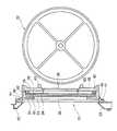
続いて、メインディスプレイ4の詳細な構造及びメインディスプレイ4の背面側においてキャビネット2内部で回転自在に設けられた3つのリール22L,22C,22Rについて、図2及び図3に基づき説明する。図2はメインディスプレイ4及びリール22L,22C,22Rの縦断面図、図3はメインディスプレイ4の分解斜視図である。[Reel and lower LCD]
Next, the detailed structure of the
図2及び図3において、メインディスプレイ4は、その前面側(図2中左側)に配置された透明タッチパネル30(以下「タッチパネル30」と略記する)と共に、スロットマシン1のキャビネット2の前面中央部に設けられた機器前面パネル20の表示窓部21の内側に配置されており、また、メインディスプレイ4の背面側(図2中右側)には、3つのリール22L,22C,22R(図2には3つのリール22L,22C,22Rのうちの1つのリールのみを示す)が並列状態で、且つ、それぞれ独立して回転自在に支持されている。 2 and 3, the
ここで、各リール22L,22C,22Rについて説明すると、3つのリール22L,22C,22Rの内、スロットマシン1のリール22Lは、メインディスプレイ4に形成される左表示窓23(図1参照)に対向しており、リール22Cは、同様にメインディスプレイ4に形成される中表示窓24(図1参照)に対向しており、また、リール22Rは、同様にメインディスプレイ4に形成される右表示窓25(図1参照)に対向している。尚、各表示窓23、24、25の構成については後述する。 Here, the
[リールのシンボル配列]
図4は、各リール22L,22C,22Rに表わされた複数種類のシンボルがそれぞれ7個配列されたシンボル列の一例を示している。この配列はデータとしてテーブル化され、後述するROM51(図5参照)に格納されている。すなわち、各シンボルには、図4に示すように“00”〜“06”のコードナンバーが付され、データテーブルとして、後で説明するROM51(図5参照)に格納されている。すなわち、リール22L,22C,22Rの区別と、コードナンバーによって、一意にシンボルが特定できる。[Reel symbol arrangement]
FIG. 4 shows an example of a symbol string in which seven types of symbols represented on each
各リール22L,22C,22Rの周面には、図4に示すように、空白シンボルを含めて7種類のシンボルが形成されている。具体的に、各リール22L,22C,22Rの周面に形成されるシンボルは、WILDシンボル91、赤7シンボル92、ボーナストリガーシンボル93、3BARシンボル94、2BARシンボル95、BARシンボル96、ブランクシンボル97である。そして、各リール22L,22C,22Rの周面には、これら7種類のシンボルが図4に示すような順序で配列されている。各リール22L,22C,22Rは、シンボル列が図4の矢印方向に移動するように回転駆動される。 As shown in FIG. 4, seven types of symbols including blank symbols are formed on the peripheral surfaces of the
尚、各シンボルの複数種類の組合せに基づき各種の当選役が予め設定されており、当選役に対応するシンボルの組合せが入賞ラインL(図1参照)上で停止した際に、当選役に応じてコインがコイン払出口15から払い出される点については従来のスロットマシンと同様であり、ここではその説明を省略する。また、各リール22の周面に各種シンボルを形成するについては、各リール22の幅・周長に合致する長尺状のシールに11個のシンボルを印刷しておき、かかるシールを各リール22の周面に貼付することにより形成するのが一般的であるが、この方法以外の方法でシンボルを形成することは勿論可能である。 Various winning combinations are set in advance based on a plurality of combinations of each symbol, and when the combination of symbols corresponding to the winning combination is stopped on the winning line L (see FIG. 1), the winning combination is determined. The point that the coins are paid out from the
ここに、本実施例では、入賞ラインLはセンターラインのみとされており、かかる入賞ラインLは、1−BETボタン11、スピンボタン12、3−BETボタン13、及び、5−BETボタン14の押下又はスタートレバー17の回動に基づき各リール22の回転・停止によるゲームを行う際に、メインディスプレイ4に表示され、一方、後述する各種ボーナスゲームの獲得時に5−BETボタン14の押下に基づきボーナスゲームを行う際には、メインディスプレイ4から表示消去される。 Here, in this embodiment, the winning line L is only the center line, and the winning line L includes the 1-
また、前記ボーナストリガーシンボル93は、各種ボーナスゲームを獲得するためのトリガーとして作用するものであり、本実施例ではリール22Rの周面にのみ1つのボーナストリガーシンボル93が設けられている。リール22Rの周面に存在するボーナストリガーシンボル93が入賞ラインL上に停止することに基づき、各種のボーナスゲームを獲得することができる。 The
[メインディスプレイ4の構造]
続いて、メインディスプレイ4の構造について、図2及び図3に基づき説明する。図2、図3において、メインディスプレイ4は、スロットマシン1の前面側から、タッチパネル30、リールガラスベース31、ベゼル金属枠32、液晶パネル33、液晶ホルダ34、拡散シート35、導光板36、白色のリフレクタ37、リアホルダ38、及び、帯電防止シート39が配置されて構成されている。拡散シート35には、開口部35A,35B,35Cが形成されており、同様に、導光板36、リフレクタ37及びリアホルダ38には、開口部35A〜35Cに一致するように、それぞれ開口部36A,36B,36C、開口部37A、37B、37C、開口部38A,38B,38Cが形成されている。各開口部35A〜38Aは、相互に一致するように重ねられて左表示窓23(図1参照)を構成し、各開口部35B〜38Bは同様に中表示窓24(図1参照)を構成し、また、各開口部35C〜38Cは同様に右表示窓25(図1参照)を構成する。[Structure of main display 4]
Next, the structure of the
ここに、拡散シート35の開口部35A〜35C及び導光板36の開口部36A〜36Cは、各リール22における可変表示の視認性を確保する透過領域を構成している。 Here, the
機器前面パネル20の表示窓部21にメインディスプレイ4を取り付けるには、図2に示すように、リールガラスベース31の上下方向に突出して設けられた各ブラケット40をネジ41により機器前面パネル20の背面にネジ止めすることにより行われている。 In order to attach the
また、導光板36の上下端には、液晶パネル33の光源として一対の冷陰極線管42が設けられている。また、リアホルダ38の各開口部38A〜38Cの背面側上下には、各リール22の外周面に形成されたシンボルを照明する一対の冷陰極線43が設けられている。 A pair of cold
液晶パネル33は、各リール22の前面に配置されて各リール22L,22C,22Rが透視されるITO等からなる透明な電気的表示パネルであり、その表示部の周囲の背面側は液晶ホルダ34によって保持されている。導光板36は、光透過性の樹脂パネルからなり、側部に位置する冷陰極線管42から出射された光を液晶パネル33の背面側に導くレンズカットが形成されている。拡散シート35は、光透過性の樹脂シートからなり、導光板36で導かれた光を拡散して、液晶パネル33に照射される光を均一化する。液晶パネル33を保持する液晶ホルダ34、拡散シート35及び導光板36は、一体化されてその周囲がベゼル金属枠32に挿入されている。この挿入により、液晶パネル33における表示部の前面側はベゼル金属枠32によって保持される。 The
ベゼル金属枠32に嵌められて一体化された液晶ホルダ34、拡散シート35及び導光板36は、その周囲が更にリールガラスベース31に挿入されており、液晶パネル33の表示前面を開口した状態でリールガラスベース31によって保持されている。タッチパネル30は、リールガラスベース31がネジ41を介して機器前面パネル20に取り付けられることにより、リールガラスベース31の前面に圧着されて、液晶パネル33の表示部前面に重ねられている。 The
リアホルダ38は、白色の樹脂板からなり、リールガラスベース31に支持されたベゼル金属枠32、液晶パネル33を保持した液晶ホルダ34、拡散シート35及び導光板36を背後からリールガラスベース31に保持している。このリアホルダ38は、冷陰極線管42から導光板36に出射された光を液晶パネル33側へ反射する反射板としても機能している。帯電防止シート39は、透明で、リアホルダ38の背面に両面テープで接着されており、リアホルダ38に形成された各開口部38A〜38Cの背面を覆っている。 The
[スロットマシン1の電気的構成]
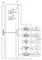
次に、スロットマシン1の制御系に係る構成について図5に基づき説明する。図5はスロットマシン1の制御系を模式的に示すブロック図である。[Electrical configuration of slot machine 1]
Next, a configuration related to the control system of the
図5において、スロットマシン1の制御系は、基本的に、CPU50を核として構成されており、CPU50にはROM51及びRAM52が接続されている。CPU50と、ROM51と、RAM52とで、スロットマシン1の主制御回路50aが構成される。ROM51は、後述するゲーム制御プログラム、ゲームの進行に伴ってサブディスプレイ3及びメインディスプレイ4に各種の演出を行うための各種演出プログラムおよび各種演出
データ、各種当選役の抽選を含む各種抽選を行うための確率抽選テーブル、その他スロットマシン1の制御上必要な各種のプログラム、データテーブル等が格納されている。また、RAM52は、CPU50で演算された各種データを一時的に記憶しておくメモリである。In FIG. 5, the control system of the
また、CPU50には、基準クロックパルスを発生するクロックパルス発生回路53及び分周器54が接続されており、また、乱数を発生する乱数発生器55及び乱数サンプリング回路56が接続されている。乱数サンプリング回路56を介してサンプリングされた乱数は、当選役、演出等の各種の抽選に使用される。更に、CPU50には、スタートレバー17に付設されるスタートスイッチ57、スピンボタン12に付設されるスピンスイッチ58、1−BETボタン11に付設される1−BETスイッチ59、3−BETボタン13に付設される3−BETスイッチ60、5−BETボタン14に付設される5−BETスイッチ61、両替ボタン6に付設される両替(CHANGE)スイッチ62、払い戻しボタン7に付設される払い戻し(CASH−OUT)スイッチ63、及びヘルプボタン8に付設されるヘルプ(HELP)スイッチ64が、それぞれ接続されている。CPU50は、各ボタンの押下により各スイッチから出力されるスイッチ信号に基づき、各ボタンに対応する各種の動作を実行すべく制御を行う。 The
更に、CPU50には、コイン投入部9に配置されるコインセンサ65及び紙幣投入部10に配置される紙幣センサ66が、それぞれ接続されている。コインセンサ65はコイン投入部9から投入されたコインを検出し、CPU50はコインセンサ65から出力されるコイン検出信号に基づき投入されたコイン枚数を演算する。紙幣センサ66は、紙幣投入部10から投入された紙幣の種類・額を検出し、CPU50は紙幣センサ66から出力される紙幣検出信号に基づき紙幣の額と等価なコイン枚数を演算する。 Furthermore, a
CPU50には、モータ駆動回路67を介して各リール22L,22C,22Rの回転をそれぞれ行う3つのステッピングモータ68L,68C,68Rが接続されおり、また、リール位置検出回路69が接続されている。CPU50からモータ駆動信号がモータ駆動回路67に出力されると、各ステッピングモータ68はモータ駆動回路67により回転駆動される。これにより各リール22L,22C,22Rの回転が行われる。 The
このとき、各リール22L,22C,22Rの回転が開始された後、ステッピングモータ68の各々に供給される駆動パルス数が計算され、その計算値はRAM52の所定エリアに書き込まれる。また、各リール22L,22C,22Rからは1回転毎にリセットパルスが出力され、かかるリセットパルスはリール位置検出回路69を介してCPU50に入力される。このようにリセットパルスがCPU50に入力されると、RAM52に書き込まれている計算値は「0」にクリアされ、CPU50は、各リール22L,22C,22Rの1回転の範囲内における回転位置に対応する計算値と、ROM51に格納された各リール22L,22C,22Rの回転位置と各リール22L,22C,22Rの周面に形成されたシンボルとを対応させたシンボルテーブルとに基づき、各リール22L,22C,22Rにおけるシンボルの回転位置を認識する。 At this time, after the rotation of the
CPU50には、ホッパー駆動回路70を介してホッパー71が接続されている。CPU50から駆動信号がホッパー駆動回路70に出力されると、ホッパー71は、所定枚数のコインをコイン払出口15から払い出す。 A
また、CPU50には、払出し完了信号回路72を介してコイン検出部73が接続されている。コイン検出部73はコイン払出口15の内部に配置されており、コイン払出口15から所定枚数のコインが払い出されたことを検出した場合には、コイン検出部73からコイン払出検出信号が払出し完了信号回路72に出力され、これに基づき払出し完了信号回路72は、CPU50に対して払出し完了信号を出力する。 Further, a
また、CPU50には、副制御回路171が接続されている。副制御回路には、サブディスプレイ3と、メインディスプレイ4と、スピーカ80L,80Rと、LED78と、タッチパネル30とが接続されている。なお、CPU50と副制御回路171との間では、双方向通信を行う。 In addition, a
さらに、CPU50には、プログレッシブインターフェース(I/F)81が付設されている。 Further, the
[副制御回路の電気的構成]
次に、図6に示される副制御回路171について説明する。副制御回路171は、サブCPU221、サブROM223、サブRAM222、画像表示制御回路74,75、音出力回路79、LED制御回路77、タッチパネル制御回路76から構成される。なお、主制御回路50aと副制御回路171との間や、サブCPU221と各アクチュエータ間には、INポートやOUTポートなどが適宜配される。[Electric configuration of sub-control circuit]
Next, the
サブCPU221は、主制御回路50aから送信された遊技情報コマンドに基づいてサブディスプレイ3およびメインディスプレイ4にどのような表示を行わせるかを決定し、画像表示制御回路74,75に表示内容を送信する。 The
サブROM223には、主制御回路50aとの通信シーケンスプログラム、スロットゲームおよびボーナスゲームに必要なプログラム並びにデータが格納されている。 The
サブRAM222は、これらの制御プログラムを実行するうえでの作業領域として利用される。 The
画像表示制御回路74はビデオROM(図示せず)とビデオRAM(図示せず)とを含んで構成され、サブディスプレイ3の表示内容を制御する。画像表示制御回路75もビデオROM(図示せず)ビデオRAM(図示せず)とを含んで構成され、メインディスプレイ4の表示内容を制御する。画像表示制御回路74,75は、主制御回路50aから送信された各種の演出コマンドに基づいて、サブディスプレイ3およびメインディスプレイ4に所定の演出画像を表示させる。 The image
音出力回路79は音源ROM(図示せず)とワークRAM(図示せず)とを含んで構成され、スピーカ80L,80Rに出力する音を制御する。音出力回路79は、主制御回路50aから送信された各種の音響演出コマンドに基づいて、スピーカ80L,80Rに所定の音響を発生させる。 The
LED制御回路77は、スロットマシン1の遊技を装飾する各種のLED78の発光を制御する。LED制御回路77は、主制御回路50aから送信された各種のLED演出コマンドに基づいて、LED78を所定のタイミングで発光させる。 The
タッチパネル制御回路76はタッチパネル30を制御して、遊技者により所定のタッチ領域画像へ接触されたことを検知し、その検知をサブCPU221に伝達する。その後、サブCPU221が所定の画像の制御を実行することによって、サブディスプレイ3およびメインディスプレイ4で各種の遊技が実行され継続される。 The touch
なお、本実施例では、サブディスプレイ3、メインディスプレイ4、スピーカ80L,80Rなどの制御を、主制御回路50aから独立した副制御回路171が行うとし、主制御回路50aと副制御回路171とは独立した別回路としているが、本発明はこれに限らず、主制御回路50aがサブディスプレイ3、メインディスプレイ4、スピーカ80L,80Rなどの制御を直接行う構成であってもよい。 In this embodiment, it is assumed that the
[遊技機が備えるボーナスゲーム]
本実施例のスロットマシン1は、次のボーナスゲームを備えている。すなわち、MAGIC LAMP BONUSと、FORTUNE ISLAND BONUSと、BANDIT’S HIDEOUT BONUSとである。MAGIC LAMP BONUS、FORTUNE ISLAND BONUS、BANDIT’S HIDEOUT BONUSは、後述するように、ボーナスゲームの入賞役に入賞したときに発生するボーナスゲームであり、このボーナスゲームの入賞役に入賞したときに行われるボーナスゲーム演出選択抽選において、イルカ(またはヘビ)演出が選択されるとMAGIC LAMP BONUSが発生し、望遠鏡演出が選択されるとBANDIT’S HIDEOUT BONUSが発生し、鳥演出が選択されるとFORTUNE ISLAND BONUSが発生する。また、このとき望遠鏡演出が選択された場合であっても、ナッジ演出(リールをハズレで一旦停止させた後に、リールを再び回転させて、ボーナストリガーシンボルを停止させる演出である。ここで、再び回転させることは、一旦停止した停止位置から目的とする停止位置までリールを微小に回転させることと、リールを再び通常どおりに回転させることと、の双方を含む)を行うとき、FORTUNE ISLAND BONUSが発生する。これらのボーナスゲームの発生プロセスと遊技性については、後述する。[Bonus game on gaming machines]
The
[プログレッシブゲームシステム]
次に、複数台のスロットマシン1を、それぞれに付設されたプログレッシブインターフェース81を介して接続したプログレッシブゲームシステムについて、図7に基づき説明する。図7はプログレッシブゲームシステム82を模式的に示す説明図である。[Progressive game system]
Next, a progressive game system in which a plurality of
図7に示すプログレッシブゲームシステム82において、複数台(本実施例では4台)のスロットマシン1は、それぞれに付設されているプログレッシブインターフェース81を介してプログレッシブユニット83の通信制御部84に接続されている。プログレッシブユニット83と各スロットマシン1との接続は、有線接続、無線接続のいずれでも可能である。これより、プログレッシブユニット83と各スロットマシン1とは、通信制御部84を介して双方向通信が可能である。 In the
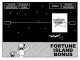
各スロットマシン1からプログレッシブユニット83に送信される情報としては、各スロットマシン1にて賭けられたコイン投入枚数情報、後述するFORTUNE ISLAND BONUSのゲームにおいて行うすごろく遊技の最終地点で、遊技者が操作するキャラクタが敵との戦いに勝利したときの情報がある。また、プログレッシブユニット83から各スロットマシン1に対して送信される情報としては、各スロットマシン1にて賭けられたコイン投入数量情報の総合計であるコインプール枚数情報がある。このようなコインのプール枚数情報は、通信制御部84を介して、プログレッシブユニット83から各スロットマシン1に送信され、各スロットマシン1におけるサブディスプレイ3に所定の時機と時間で表示される。コインプール枚数情報が示すプログレッシブ値として蓄積されたコインの一部または全部が、FORTUNE ISLAND BONUSのゲームにおいて行うすごろく遊技の最終地点で、遊技者が操作するキャラクタが敵との戦いに勝利する(このことを、以下、FORTUNE ISLAND BONUS当選という)ことができたスロットマシン1の遊技者に対して、ジャックポットとして付与される。 Information transmitted from each
そして、プログレッシブユニット83におけるプール枚数演算部85は、各スロットマシン1から送信されてくるコイン投入情報に基づき、FORTUNE ISLAND BONUSについて初期枚数を900枚(本発明はこれに限定されず、任意に設定変更可能であるとする)とし、各スロットマシン1で投入されたコイン枚数の1.7%(本発明はこれに限定されず、任意に設定変更可能であるとする)を初期枚数に累積的に加算する、共通ボーナスの加算を行う。 Then, the pool
尚、各スロットマシン1において、いずれかのスロットマシン1の遊技者がジャックポットの配当を獲得した場合には、プログレッシブ値に対応するコインプール枚数情報は初期枚数にリセットされる。また、プール枚数記憶部86は、前記のようにプール枚数演算部85にて演算されたコイン枚数を記憶する。 In each
前記のように構成されたプログレッシブユニット83は、通信制御部84から各スロットマシン1に対して、プール枚数記憶部86に記憶されている各共通ボーナスのコインプール枚数情報を定期的に送信する。各スロットマシン1では、プログレッシブユニット83から送信されてくるコインプール枚数情報に基づき、前回送信されたコインプール枚数情報と今回送信されたコインプール枚数情報とを定期的に比較し、今回のコインプール枚数が前回のコインプール枚数よりも減少している場合には、FORTUNE ISLAND BONUSにつき当選があったことを報知する。 The
従って、プログレッシブユニット83から各スロットマシン1に送信される情報が限定されている場合においても、FORTUNE ISLAND BONUSに当選したことが他のスロットマシン1でも報知されるので、当選した遊技者のみならず他のスロットマシン1の遊技者は、FORTUNE ISLAND BONUS当選に対して、プールされているコインが配当されたことをサブディスプレイ3又はメインディスプレイ4で容易に確認することができ、これによりFORTUNE ISLAND BONUSに対する遊技者の関心を増大させて興趣を盛り上げることができる。また、複数の各共通ボーナス毎に、当選の報知を行うことが可能であり、従って、いずれの共通ボーナスに係るコインが獲得されたかを容易に確認することもできる。 Therefore, even when the information transmitted from the
また、スロットマシン1にて、FORTUNE ISLAND BONUSに当選した場合、プログレッシブユニット83は、前記したように、ボーナスゲームに相関する各プログレッシブボーナスのコインのプール枚数情報を、通信制御部84を介して、各スロットマシン1に送信し、また、スロットマシン1では、そのコインのプール枚数情報をサブディスプレイ3に表示する。これよりFORTUNE ISLAND BONUS獲得への期待感、関心を増大して興趣を盛り上げることができる。 In addition, when FORTUNE ISLAND BONUS is won in the
[通常ゲーム用確率抽選テーブル]
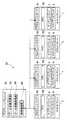
図8は、スロットマシン1の通常ゲームにおける入賞役を決定するための確率抽選で使用される確率抽選テーブルである。各リール22L,22C,22Rに描かれたシンボルに対して、抽出された乱数値がどの範囲に属するかによって停止させるシンボルを決定する。リール22L,22C,22R毎に、独立に抽出した乱数値に基づき、各リール22L,22C,22Rのシンボルが決定される。[Normal game probability lottery table]
FIG. 8 is a probability lottery table used in the probability lottery for determining the winning combination in the base game of the
図8は、通常ゲームにおいて、遊技者によりスロットマシン1にBETされた(賭けられた)コインの枚数が5枚であるとき、抽出されたそれぞれの乱数値に対して各リール22L,22C,22Rにおいていずれのシンボルが選択されるかを示す確率抽選テーブルである。例えば、リール22Lに対して抽選された乱数値が“10”のときには、リール22Lが停止して示されるシンボルは“WILD”であり、リール22Cに対して抽選された乱数値が“25”のときには、リール22Cが停止して示されるシンボルは“赤7”であり、リール22Rに対して抽選された乱数値が“65”のときには、リール22Rが停止して示されるシンボルはボーナストリガーシンボル93(図4参照)である。このようにして各リール22L,22C,22Rのそれぞれに停止するシンボルが決定される。 FIG. 8 shows that in a normal game, when the number of coins betted (betted) to the
なお、図8に示されるブランク1およびブランク2なるシンボルと、図4に示す複数のブランクシンボル97との対応は、特に限定されていない。例えば、図8の確率抽選テーブルのリール22Lにおいてブランク1が選択されると、図4のリール22Lのシンボル列においては、コードナンバー“02”が付されたシンボルとコードナンバー“06”が付されたシンボルとのいずれかが入賞ラインL上に停止されるように停止制御される。同様に、図8の確率抽選テーブルのリール22Lにおいてブランク2が選択されると、図4のリール22Lのシンボル列においては、コードナンバー“02”が付されたシンボルとコードナンバー“06”が付されたシンボルとのいずれかが入賞ラインL上に停止されるように停止制御される。 Note that the correspondence between the blank 1 and blank 2 symbols shown in FIG. 8 and the plurality of
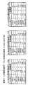
[MAGIC LAMP BONUS用確率抽選テーブル]
図9は、スロットマシン1のMAGIC LAMP BONUSゲームにおける入賞役を決定するための確率抽選で使用される確率抽選テーブルである。各リール22L,22C,22Rに描かれたシンボルに対して、抽出された乱数値がどの範囲に属するかによって停止させるシンボルを決定する。各リール22L,22C,22Rに共通して唯一抽出した乱数値に基づき、各リール22L,22C,22Rのシンボルが決定される。例えば、抽選された乱数値が“10”のときには、リール22L,22C,22Rが停止して示されるシンボルはすべて“赤7”である。このようにして、抽選された一の乱数値に対して各リール22L,22C,22Rのそれぞれに停止するシンボルが一意に決定され、その決定されたシンボルは全て同一である。すなわち、MAGIC LAMP BONUSゲームにおいては、入賞役の確率抽選において、“WILD”、“赤7”、“3BAR”、“2BAR”、“BAR”のいずれかの入賞役が、必ず選択される。[MAGIC LAMP BONUS probability lottery table]
FIG. 9 is a probability lottery table used in the probability lottery for determining a winning combination in the MAGIC LAMP BONUS game of the
[入賞役判定テーブル]
前述したように、スロットマシン1の通常ゲーム時においては、各リール22L,22C,22Rに対してそれぞれ独立した乱数値を抽出し、それぞれの乱数値に基づき各リール22L,22C,22R毎に停止シンボルを決定している。このため、各リール22L,22C,22Rが停止したときに、その停止態様が入賞役を形成しているか否かを判定する処理が必要になる。図10に示す入賞役判定テーブルは、この判定処理に使用されるテーブルである。各リール22L,22C,22Rの停止態様を判定して、例えば、停止態様が“赤7−赤7−赤7”であるときには、入賞役は“赤7”であると判定し、図10に示すようにBET数に応じた所定の配当を遊技者に付与する。図10において、停止シンボルが“ANYBAR−ANYBAR−ANYBAR”であるとは、各リール22L,22C,22Rそれぞれの停止シンボルが、“3BAR”、“2BAR”、“BAR”のいずれであってもよいことを示す。停止シンボルが図10に示す特定の態様である場合以外は、入賞役は“ハズレ”である。[Winning position determination table]
As described above, in the normal game of the
なお、図10に示す、入賞役に応じた入賞時配当枚数の数値は、後述するように、通常ゲーム時またはMAGIC LAMP BONUSゲーム時に、サブディスプレイ3に表示される配当表の情報の基礎となる情報である。すなわち、通常ゲーム時においては、図10に示す、入賞役に応じた入賞時配当枚数の数値がそのまま配当表に表示され、MAGIC LAMP BONUSゲーム時においては、MAGIC LAMP BONUSゲームが発生したときに遊技者がBETしていたコインのBET数に該当する各入賞役に対する配当数の数値を、所定の抽選により1倍(すなわち、この場合には数値の変更はない)、2倍または3倍にした数値を配当表に表示する。例えば、MAGIC LAMP BONUSゲームが発生した単位遊技において遊技者が2BETしていた場合に、所定の抽選により配当を2倍にすると決定されたときに、図10の、各入賞役に対応する2BETの入賞時配当枚数をすべて2倍にした数値を配当表に表示する。 Note that the numerical value of the payout amount corresponding to the winning combination shown in FIG. 10 is the basis of information on the payout table displayed on the
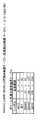
[通常画面選択確率テーブル]
図11は、スロットマシン1における通常ゲームを行うときに、メインディスプレイ4に表示する演出画面を選択する抽選に使用される確率抽選テーブルである。抽出された乱数値に基づいて、メインディスプレイ4に表示する演出画面を選択する抽選を行うが、このとき決定された通常画面に基づいて、所定の単位遊技の間、メインディスプレイ4に表示される演出が異なる。例えば、通常画面に“海”が選択されたときには、メインディスプレイ4においては、メインキャラクタが航海する過程で様々なイベントに遭遇する演出がおこなわれ、通常画面に“砂漠”が選択されたときには、メインディスプレイ4においては、メインキャラクタが砂漠を旅する過程で様々なイベントに遭遇する演出がおこなわれる。一の乱数を抽出し、例えば、その乱数値が“100”であったときには、通常画面は“海”が選択される。[Normal screen selection probability table]
FIG. 11 is a probability lottery table used for a lottery for selecting an effect screen to be displayed on the
[リール停止順序決定確率抽選テーブル]
図12は、リール停止順序決定確率抽選を行うときに参照される確率抽選テーブルである。リール22L,22C,22Rは、その停止順序が抽選により決定される。この抽選は、リール22Rにボーナストリガーシンボル93が選択されているとき(すなわち、入賞役がボーナスゲームであるとき)以外に行われる。一の乱数を抽選し、どの停止順序に該当する範囲にその乱数値が含まれるかによって、本実施例では、リール22L,22C,22Rの停止順序が決定される。リールの停止順序が22L,22C,22Rである停止順序を第1停止順序、停止順序が22L,22R,22Cである停止順序を第2停止順序、停止順序が22C,22L,22Rである停止順序を第3停止順序、停止順序が22C,22R,22Lである停止順序を第4停止順序、停止順序が22R,22L,22Cである停止順序を第5停止順序、停止順序が22R,22C,22Lである停止順序を第6停止順序という。たとえば、抽出された乱数値が“95”のときには、第2停止順序(すなわち、リール22L、リール22R、リール22Cの順序で停止が行われる停止順序)が選択される。スロットマシン1は、この選択された停止順序に従って、リール22L,22C,22Rが順次、停止制御される。[Reel stop order determination probability lottery table]
FIG. 12 is a probability lottery table that is referred to when the reel stop order determination probability lottery is performed. The
[ボーナスゲーム演出選択確率抽選テーブル]
図13は、リール22Rにボーナストリガーシンボル93が選択されているとき(すなわち、入賞役がボーナスゲームのとき)であって、コインのBET数(遊技者によって通常ゲームに賭けられたコインの枚数)が5BET(5枚)のときに、メインディスプレイ4で行う演出の選択のために使用される確率抽選テーブルである。この確率抽選によって演出が決定されることより、リール22Rにボーナストリガーシンボル93が停止することが決定されているとき、MAGIC LAMP BONUSを発生させるか、FORTUNE ISLAND BONUSを発生させるか、あるいはBANDIT’S HIDEOUT BONUSを発生させるか、の振り分けが決定される。例えば、一の乱数を抽出し、その乱数が“80”であったときには、メインディスプレイ4では望遠鏡演出が実行され、最終的にBANDIT’S HIDEOUT BONUSが発生する。ただし、後述するように、メインディスプレイ4では望遠鏡演出が実行されても、前述のナッジ演出を行う場合には、最終的にFORTUNE ISLAND BONUSが発生する。また、一の乱数を抽出し、その乱数が“150”であったときには、メインディスプレイ4では鳥演出が実行され、最終的にFORTUNE ISLAND BONUSが発生する。また、一の乱数を抽出し、その乱数が“200”であったときには、メインディスプレイ4ではイルカ(ヘビ)演出が実行され、最終的にMAGIC LAMP BONUSが発生する。[Bonus game production selection probability lottery table]
FIG. 13 shows a case where the
なお、リール22Rにボーナストリガーシンボル93が選択されているときであって、コインのBET数が1BET(1枚)、2BET(2枚)、または3BET(3枚)のときは、メインディスプレイ4で行う演出の選択の抽選は行われず、リール22Rにボーナストリガーシンボル93が停止することが決定されているときには、必ずBANDIT’S HIDEOUT BONUSを発生させるように制御される。 When the
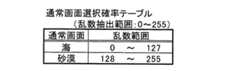
[ボーナストリガーシンボル選択時のナッジ演出決定確率抽選テーブル]
図14は、リール22Rにボーナストリガーシンボル93が選択されているとき(すなわち、入賞役がボーナスゲームのとき)に、ナッジ演出を行うか否かを決定する際に使用される確率抽選テーブルである。例えば、一の乱数を抽出して、その乱数値が“100”であっときには、ナッジ演出を行わないと決定し、一方、“130”であったときには、ナッジ演出を行うと決定する。この決定に従って、スロットマシン1のリール22Rおよびメインディスプレイ4において、視覚的に互いに連携するようにナッジ演出が実行される。[Nudge production decision probability lottery table when bonus trigger symbol is selected]
FIG. 14 is a probability lottery table used when determining whether or not to perform a nudge effect when the
[スロットマシン1の通常ゲームに視覚的に連携する、メインディスプレイ4に表示される演出について]
スロットマシン1の通常ゲームに視覚的に連携する、メインディスプレイ4に表示される演出には、次のものがある。演出は、リール22L,22C,22Rの回転が開始されたときに、リール22L,22C,22Rの回転が停止する以前にすでに決定されている入賞役に応じて分類することができる。演出は、入賞役が“ボーナスゲーム”のときに行われる、「望遠鏡演出」と「鳥演出」、入賞役が“ワイルド”、“赤7”“3BAR”、“2BAR”、“BAR”、“ANYBAR”のときに行われる「成功演出」、入賞役が“ハズレ”のときに行われる「失敗演出」に大別される。[About the effects displayed on the
The effects displayed on the
「望遠鏡演出」と「鳥演出」は、入賞役が“ボーナスゲーム”であり、リール22Rにボーナストリガーシンボル93を停止させることが予め決定されているので、そのボーナストリガーシンボル93を停止させるまでに実行される演出である。前述の通り「望遠鏡演出」と「鳥演出」のいずれを実行するかは、確率抽選によって決定される。さらに、「望遠鏡演出」は、基本的にBANDIT’S HIDEOUT BONUSを発生させる演出であり、ナッジ演出が実行されるときにはFORTUNE ISLAND BONUSを発生させる演出である。 “Telescope effect” and “bird effect” are “bonus games” in which the winning combination is made, and since it is determined in advance that the
「成功演出」は、入賞役が“ワイルド”、“赤7”“3BAR”、“2BAR”、“BAR”、“ANYBAR”のいずれかであるときに実行される演出であり、さらに「イルカ成功演出」、「ヘビ成功演出」、「カモメ成功演出」、「ハゲタカ成功演出」、「サル成功演出」に分類される。「イルカ成功演出」、「カモメ成功演出」、「サル成功演出」は、通常画面として“海”が選択されているときに実行される演出である。「ヘビ成功演出」、「ハゲタカ成功演出」、「サル成功演出」は、通常画面として“砂漠”が選択されているときに実行される演出である。 “Successful production” is a production executed when the winning role is “Wild”, “
「イルカ成功演出」および「ヘビ成功演出」は、通常ゲームにおいてイルカまたはヘビがリール22L,22C,22Rの停止に合わせてメインディスプレイ4に出現し、最後に停止するリールの回転停止前後に合わせて、イルカまたはヘビがメインキャラクタに「ランプ」を渡す演出である。そしてその「ランプ」から「召使」が現れて、MAGIC LAMP BONUSが発生する。 “Dolphin success production” and “snake success production” are performed in the normal game in accordance with before and after the stop of rotation of the reel that the dolphin or the snake appears on the
なお、停止するリールの回転停止前後に合わせて、メインディスプレイ4に表示される演出画像が制御される方法には、詳しくは次の3つの態様がある。停止するリールの回転停止前後に合わせて、メインディスプレイ4に表示される演出画像が制御される場合は、以下の3つの態様のいずれかである。 In addition, the method of controlling the effect image displayed on the
1つ目は、リールの停止制御後に画像演出を行う場合である。この場合、リールの停止制御を行うと同時に演出コマンドを送信する。例えば、リール22Cの停止制御を行うと同時に、リール22Cに関連する演出コマンド(例えば、図21のカモメ演出コマンド2など)を送信すると、リール22Cが停止した後に、画像演出が開始される。なお、リール22L,Rも同様の制御方法が適用可能である。この場合の例としては、カモメ成功(または失敗)演出などがある。 The first is a case where an image effect is performed after reel stop control. In this case, the production command is transmitted simultaneously with the reel stop control. For example, when an effect command related to the
2つ目は、リールの停止制御前に画像演出を行う場合である。各リールに対応する演出データに基づく画像演出には、それぞれ所定の演出実行時間が定められており、演出コマンドを送信し、その所定の演出実行時間が経過してから、リールの停止制御が行われる。例えば、リール22Cの演出コマンドに基づく画像演出には2秒の演出実行時間が定められており、その2秒の演出実行時間の経過後にリール22Cの停止制御が行われる。なお、リール22L,Rも同様の制御方法が適用可能である。この場合の例としては、サル成功(または失敗)演出、カモメ成功(または失敗)演出などがある。 The second is a case where an image effect is performed before the reel stop control. The image production based on the production data corresponding to each reel has a predetermined production execution time, and after the production command is transmitted and the predetermined production execution time elapses, the reel stop control is performed. Is called. For example, an effect execution time of 2 seconds is set for the image effect based on the effect command of the
3つ目は、リールの停止制御前後に画像演出を行う場合である。各リールに対応する演出データに基づく画像演出には、それぞれ所定の演出実行時間が定められており、演出コマンドを送信し、その所定の演出実行時間の経過途中に、リールの停止制御が行われる。例えば、リール22Cの演出コマンドに基づく画像演出には4秒の演出実行時間が定められており、演出実行が開始されてから2秒経過後にリール22Cの停止制御が行われる。リール22Cが停止制御された後も、残りの2秒間にわたって画像演出が行われる。なお、リール22L,Rも同様の制御方法が適用可能である。 The third is a case where an image effect is performed before and after reel stop control. For the image effects based on the effect data corresponding to each reel, a predetermined effect execution time is set, an effect command is transmitted, and reel stop control is performed in the course of the predetermined effect execution time. . For example, the effect execution time of 4 seconds is set for the image effect based on the effect command of the
「カモメ成功演出」および「ハゲタカ成功演出」は、通常ゲームにおいてカモメまたは「ハゲタカ」がリール22L,22C,22Rの停止に合わせてメインディスプレイ4に出現し、リール22L,22C,22Rのそれぞれの回転停止前後に合わせて、「カモメ」または「ハゲタカ」がリールの表示窓23,24,25の枠内に留まる演出である。この演出によれば、「カモメ」または「ハゲタカ」が表示窓23,24,25の枠内に留まることによって、特定の入賞役が成立する可能性があることを遊技者に報知することができる。 In the “game of gull success” and “game of vulture success”, the gull or “vulture” appears on the
「サル成功演出」は、通常ゲームにおいて「サル」がリール22L,22C,22Rの停止に合わせてメインディスプレイ4に出現し、リール22L,22C,22Rのそれぞれの回転停止直前に、「サル」が次に停止するリールの表示窓23,24,25のいずれかにぶら下がる演出である。この演出によれば、「サル」が次に停止するリールの表示窓23,24,25のいずれかにぶら下がることによって、次に停止するリールを遊技者に報知することができ、さらに特定の入賞役が成立する可能性があることを遊技者に報知することができる。 In the “monkey success production”, “monkey” appears on the
「失敗演出」は、入賞役が“ハズレ”であるときに実行される演出であり、さらに「イルカ失敗演出」、「ヘビ失敗演出」、「カモメ失敗演出」、「ハゲタカ失敗演出」、「サル失敗演出」、「望遠鏡失敗演出」、「鳥失敗演出」に分類される。「イルカ失敗演出」、「カモメ失敗演出」、「サル失敗演出」、「望遠鏡失敗演出」、「鳥失敗演出」は、通常画面として“海”が選択されているときに実行される演出である。「ヘビ成功演出」、「ハゲタカ成功演出」、「サル成功演出」、「望遠鏡失敗演出」、「鳥失敗演出」は、通常画面として“砂漠”が選択されているときに実行される演出である。ここで、実行される「失敗演出」は、リール22L,22C,22Rの停止順序に依存する。リール22L,22C,22Rの停止順序が第1停止順序のときには、「イルカ(ヘビ)失敗演出」、「カモメ(ハゲタカ)失敗演出」、「サル失敗演出」、「望遠鏡失敗演出」、「鳥失敗演出」の中から一の演出を抽選するが、リール22L,22C,22Rの停止順序が第1停止順序以外のときには、「イルカ(ヘビ)失敗演出」、「カモメ(ハゲタカ)失敗演出」、「サル失敗演出」の中から一の演出を抽選する。これは、リール22Rにボーナストリガーシンボル93が停止されることが決定されているときは、必ず第1停止順序でリール22L,22C,22Rの回転が停止されるので、逆に入賞役が“ハズレ”の場合で、第1停止順序でリール22L,22C,22Rの回転が停止されるときも、ボーナストリガーシンボル93がリール22Rに停止する可能性に対する期待感を遊技者に抱かせる効果がある。 “Failure production” is a production executed when the winning role is “losing”, and further, “Dolphin failure production”, “Snake failure production”, “Gull seagull production”, “Vulture failure production”, “Monkey” It is classified into “failure production”, “telescope failure production”, and “bird failure production”. “Dolphin failure production”, “gull failure production”, “monkey failure production”, “telescope failure production”, and “bird failure production” are effects executed when “sea” is selected as the normal screen. . “Snake Success Production”, “Vulture Success Production”, “Monkey Success Production”, “Telescope Failure Production”, “Bird Failure Production” are productions executed when “Desert” is selected as the normal screen. . Here, the “failure effect” to be executed depends on the stop order of the
[入賞役(ボーナスゲーム、ハズレを除く)に応じた演出選択確率抽選テーブル]
図15は、「成功演出」が、ボーナスゲームおよびハズレ以外の入賞役に応じて選択される抽選に使用される確率抽選テーブルである。[Production selection probability lottery table according to winning combination (excluding bonus game and lose)]
FIG. 15 is a probability lottery table used for the lottery in which the “success effect” is selected according to the winning combination other than the bonus game and the loss.
通常画面が“海”のときには、「イルカ成功演出」、「カモメ成功演出」、「サル成功演出」の3つの演出の中から所定の確率で演出が抽選され、通常画面が“砂漠”のときには、「ハゲタカ成功演出」、「ヘビ成功演出」、「サル成功演出」の3つの演出の中から所定の確率で演出が抽選される。どの演出が抽選されるかは、図15に示されるように、入賞役によって異なる。その抽選の確率分布の特徴は、“WILD”のように入賞確率が低い入賞役であるほど、「カモメ(ハゲタカ)成功演出」が抽選される確率が高い。このように、入賞役毎に演出が選択される確率を異ならせることによって、演出の多様性を向上させることができる。 When the normal screen is “Sea”, the effects are drawn with a predetermined probability from the three effects of “Dolphin success production”, “Gull success production”, and “Monkey success production”. When the normal screen is “Desert” From the three effects of “Vulture Success Produce”, “Snake Success Produce”, and “Monkey Success Produce”, the effects are selected with a predetermined probability. Which production is selected by lottery varies depending on the winning combination as shown in FIG. The feature of the probability distribution of the lottery is that, as the winning combination has a lower winning probability, such as “WILD”, the probability that the “gull (vulture) successful production” will be drawn is higher. Thus, the diversity of production can be improved by varying the probability that the production is selected for each winning combination.
[入賞役がハズレのときの失敗演出選択確率抽選テーブル]
図16は、「失敗演出」が、リール22L,22C,22Rの停止順序に応じて選択される抽選に使用される確率抽選テーブルである。[Failure production selection probability lottery table when the winning role is lost]
FIG. 16 is a probability lottery table used for the lottery in which “failure effect” is selected according to the stop order of the
リール22L,22C,22Rの停止順序が第1停止順序であって、通常画面が“海”のときには、「イルカ失敗演出」、「カモメ失敗演出」、「サル失敗演出」、「望遠鏡失敗演出」、「鳥失敗演出」の5つの演出の中から所定の確率で演出が抽選され、通常画面が“砂漠”のときには、「ハゲタカ失敗演出」、「ヘビ失敗演出」、「サル失敗演出」、「望遠鏡失敗演出」、「鳥失敗演出」の5つの演出の中から所定の確率で演出が抽選される。一の抽出乱数値に対してどの演出が選択されるかは、図16に示されるとおりである。 When the stop order of the
また、リール22L,22C,22Rの停止順序が第1停止順序以外であって、通常画面が“海”のときには、「イルカ失敗演出」、「カモメ失敗演出」、「サル失敗演出」の3つの演出の中から所定の確率で演出が抽選され、通常画面が“砂漠”のときには、「ハゲタカ失敗演出」、「ヘビ失敗演出」、「サル失敗演出」の3つの演出の中から所定の確率で演出が抽選される。一の抽出乱数値に対してどの演出が選択されるかは、図16に示されるとおりである。 Further, when the stop order of the
[MAGIC LAMP BONUS終了予兆演出確率抽選テーブル]
図17は、MAGIC LAMP BONUSが実行され、所定回数(本実施例では3回とするがこれに限定されない)の実行が消化された後に、MAGIC LAMP BONUSが終了する予兆を示す演出を実行するか否かを決定する抽選に使用する確率抽選テーブルである。一の抽出乱数値に対してMAGIC LAMP BONUSの終了予兆を行うか否かの選択は、図17に示されるとおりにしたがって決定される。[MAGIC LAMP BONUS end prognostic effect probability lottery table]
FIG. 17 shows whether or not to produce an effect indicating a sign that MAGIC LAMP BONUS will end after MAGIC LAMP BONUS has been executed and execution has been completed a predetermined number of times (three times in this embodiment, but not limited to this). It is a probability lottery table used for the lottery to determine whether or not. The selection as to whether or not to perform the MAGIC LAMP BONUS completion sign for one extracted random number value is determined as shown in FIG.
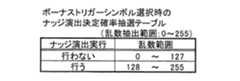
[MAGIC LAMP BONUS終了予兆演出を行うときのMAGIC LAMP BONUS終了確率抽選テーブル]
図18は、MAGIC LAMP BONUSが実行され、所定回数(本実施例では3回とするがこれに限定されない)の実行が消化された後に、MAGIC LAMP BONUSが終了する予兆を示す演出が実行すると決定されたとき、MAGIC LAMP BONUSを実際に終了させるか否かを決定する抽選に使用する確率抽選テーブルである。一の抽出乱数値に対してMAGIC LAMP BONUSを終了させるか否かの選択は、図18に示されるとおりにしたがって決定される。[MAGIC LAMP BONUS end probability lottery table when performing MAGIC LAMP BONUS end indication effect]
FIG. 18 shows that after MAGIC LAMP BONUS is executed and execution of a predetermined number of times (three times in this embodiment, but not limited to this) is completed, an effect indicating a sign that MAGIC LAMP BONUS will end is executed. This is a probability lottery table used for a lottery to determine whether or not to actually end MAGIC LAMP BONUS when it is done. The selection of whether or not to end MAGIC LAMP BONUS for one extracted random number value is determined according to FIG.
[配当表示変更パターン確率抽選テーブル]
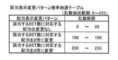
図19は、MAGIC LAMP BONUSが発生するときに、BET数に応じて遊技者に付与される配当に関する配当情報を変更する変更パターンを決定する抽選に使用される確率抽選テーブルである。この変更された配当情報に基づき、サブディスプレイ3に表示する配当表が変更される。MAGIC LAMP BONUSが発生時に変更する配当情報は、MAGIC LAMP BONUSが発生した単位ゲームにおけるBET数に該当する配当情報のみである。例えば、MAGIC LAMP BONUSが発生したゲーム内において、遊技者が2BET(2枚のコインを遊技に賭ける)していた場合は、2BETの場合の配当情報のみを変更する。配当情報の変更パターンは、本実施例では、“該当するBET数に対応する配当の変更なし”、“該当するBET数に対応する配当を2倍に変更”、“該当するBET数に対応する配当を3倍に変更”の3つのパターンがある(本発明はこれに限定されず、倍率を抽選する、配当数を抽選によって決定するなど更に多様な方法でもよい)。一の抽出乱数値に対して、どの変更パターンが選択されるかは、図19に示されるとおりである。[Dividend display change pattern probability lottery table]
FIG. 19 is a probability lottery table used in a lottery for determining a change pattern for changing payout information related to a payout to be awarded to a player according to the number of BETs when MAGIC LAMP BONUS occurs. Based on the changed payout information, the payout table displayed on the
以上、各種の確率抽選テーブルを説明したが、本発明はこれらに限られるものではなく、確率分布や抽選されうる選択肢のバリエーションなどは、遊技性を高めるために設計変更可能である。 Although various probability lottery tables have been described above, the present invention is not limited to these, and the probability distribution and the variations of options that can be selected can be changed in design in order to enhance game playability.
[通常画面演出データテーブル]
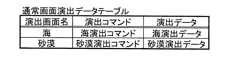
図20は、通常画面演出を指令する演出コマンドと演出データとを格納したテーブルを示す図である。このテーブルは、所定のデータ形式で、副制御回路171のサブROM223に格納されている。また、演出コマンドが、主制御回路50aのROM51に格納されている。主制御回路50aが所定の演出の実行を副制御回路171に指令するときに、ROM51から該当する演出コマンドを読出し、その演出コマンドを副制御回路171に送信する。そのコマンドを受信した副制御回路171では、サブCPU221が、受信したコマンドに該当する演出データをサブROM223から読み出して、画像表示制御回路75を駆動して目的とする演出画像をメインディスプレイ4に表示する。なお、演出データテーブルの格納方法、演出コマンドの送信方法、該演出コマンドの受信に従って実行される各処理などは、後述する「ボーナスゲーム、ハズレを除く入賞役のリール停止演出データテーブル」、「入賞役がハズレのときのリール停止演出データテーブル」、「MAGIC LAMP BONUS中遊技演出データテーブル」、「MAGIC LAMP BONUS終了演出データテーブル」、「ボーナスゲーム演出データテーブル」、「BANDIT’S HIDEOUT BONUS演出データテーブル」、「FORTUME ISLAND BONUS演出データテーブル」も同様である。通常画面には、“海”と“砂漠”があり、それぞれの演出コマンドおよび演出データは、「海演出コマンド」および「海演出データ」と、「砂漠演出コマンド」および「砂漠演出データ」である。[Normal screen effect data table]
FIG. 20 is a diagram showing a table storing effect commands for instructing normal screen effects and effect data. This table is stored in the
[ボーナスゲーム、ハズレを除く入賞役のリール停止演出データテーブル]
図21は、ボーナスゲーム、ハズレを除く入賞役のリール停止演出を指令する演出コマンドと演出データとを格納したテーブルを示す図である。このテーブルには、「成功演出」に関する演出コマンドと演出データが収められている。ボーナスゲーム、ハズレを除く入賞役のリール停止演出には、「カモメ成功演出」、「ハゲタカ成功演出」、「サル成功演出」があり、それぞれの演出コマンドおよび演出データは、図21に示されるとおりである。[Reel stop effect data table for winning roles excluding bonus games and losers]
FIG. 21 is a diagram showing a table storing effect commands and effect data for instructing reel stop effects for winning combinations excluding bonus games and lost games. This table stores production commands and production data related to “success production”. Reel stop effects for winning roles excluding bonus games and lost games include “gull success production”, “vulture success production”, and “monkey success production”, and the production commands and production data are as shown in FIG. It is.
[入賞役がハズレのときのリール停止演出データテーブル]
図22は、入賞役がハズレのときのリール停止演出を指令する演出コマンドと演出データとを格納したテーブルを示す図である。このテーブルには、「失敗演出」に関する演出コマンドと演出データが収められている。入賞役がハズレのときのリール停止演出には、「イルカ失敗演出」、「ヘビ失敗演出」、「カモメ失敗演出」、「ハゲタカ失敗演出」、「サル失敗演出」、「望遠鏡失敗演出」、「鳥失敗演出」があり、それぞれの演出コマンドおよび演出データは、図22に示されるとおりである。[Reel stop effect data table when the winning combination is lost]
FIG. 22 is a diagram showing a table storing effect commands and effect data for instructing a reel stop effect when the winning combination is lost. This table stores production commands and production data related to “failure production”. When the winning role is lost, the reel stop production includes “Dolphin Failure Production”, “Snake Failure Production”, “Gull Failure Production”, “Vulture Failure Production”, “Monkey Failure Production”, “Telescope Failure Production”, “ There is a “bird failure effect”, and each effect command and effect data are as shown in FIG.
[MAGIC LAMP BONUS中遊技演出データテーブル]
図23は、MAGIC LAMP BONUS中遊技演出を指令する演出コマンドと演出データとを格納したテーブルを示す図である。このテーブルには、MAGIC LAMP BONUS実行中にメインディスプレイ4に表示する演出画像のデータが収められている。MAGIC LAMP BONUS中遊技演出には、「リール回転開始演出」、「召使魔法演出」があり、それぞれの演出コマンドおよび演出データは、図23に示されるとおりである。[MAGIC LAMP BONUS medium game effect data table]
FIG. 23 is a diagram showing a table storing effect commands for directing game effects during MAGIC LAMP BONUS and effect data. This table stores effect image data to be displayed on the
[MAGIC LAMP BONUS終了演出データテーブル]
図24は、MAGIC LAMP BONUS終了演出を指令する演出コマンドと演出データとを格納したテーブルを示す図である。このテーブルには、MAGIC LAMP BONUS実行中にMAGIC LAMP BONUSを終了する予兆の演出およびMAGIC LAMP BONUSを終了する演出をメインディスプレイ4に表示する演出画像のデータが収められている。MAGIC LAMP BONUS終了演出には、「MAGIC LAMP BONUS終了予兆演出」、「召使踏ん張り演出」、「召使画面に踏みとどまった演出」、「召使画面から退場演出」があり、それぞれの演出コマンドおよび演出データは、図24に示されるとおりである。[MAGIC LAMP BONUS end effect data table]
FIG. 24 is a diagram showing a table storing effect commands and effect data for instructing a MAGIC LAMP BONUS end effect. This table stores data of effect images for displaying on the
[ボーナスゲーム演出データテーブル]
図25は、ボーナスゲーム演出を指令する演出コマンドと演出データとを格納したテーブルを示す図である。このテーブルには、入賞役として“ボーナスゲーム”が選択されたとき、または入賞役として“ハズレ”が選択されたが、リール22L,22C,22Rの停止順序が第1停止順序で、「失敗演出」に「望遠鏡失敗演出」、「鳥失敗演出」、「イルカ成功演出」、または「ヘビ成功演出」が選択されたときの演出をメインディスプレイ4に表示する演出画像のデータが収められている。それぞれのボーナスゲーム演出の演出コマンドおよび演出データは、図25に示されるとおりである。[Bonus Game Effect Data Table]
FIG. 25 is a diagram showing a table storing effect commands for directing bonus game effects and effect data. In this table, when “bonus game” is selected as the winning combination or “losing” is selected as the winning combination, the stop order of the
[BANDIT’S HIDEOUT BONUS演出データテーブル]
図26は、BANDIT’S HIDEOUT BONUS実行演出を指令する演出コマンドと演出データとを格納したテーブルを示す図である。このテーブルには、入賞役としてボーナスゲームが選択され、さらにボーナスゲーム演出選択確率抽選(この抽選は、5BET時のみ実行される)において望遠鏡演出が選択されBANDIT’S HIDEOUT BONUSが発生し実行されるとき、BANDIT’S HIDEOUT BONUSの実行演出画像をメインディスプレイ4に表示する演出画像のデータが収められている。BANDIT’S HIDEOUT BONUS実行演出には、「BANDIT’S HIDEOUT BONUS開始演出」、「宝箱オープン演出」、「宝箱から財宝が現れる演出」、「宝箱からラッキーアイテムが現れる演出」、「財宝を獲得して喜ぶメインキャラクタ演出」、「ラッキーアイテムを獲得して喜ぶメインキャラクタ演出」、「宝箱から骸骨が現れる演出」、「骸骨に追われて逃げ出すメインキャラクタ演出」があり、それぞれの演出コマンドおよび演出データは、図26に示されるとおりである。[BANDIT'S HIDEOUT BONUS production data table]
FIG. 26 is a diagram showing a table storing effect commands and effect data for instructing BANDIT'S HIDEOUT BONUS execution effects. In this table, when a bonus game is selected as a winning combination, and when a telescope effect is selected and executed in a bonus game effect selection probability lottery (this lottery is executed only at 5 BET) and BANDIT'S HIDEOUT BONUS is generated, The data of the effect image which displays the execution effect image of BANDIT'S HIDEOUT BONUS on the
[FORTUME ISLAND BONUS演出データテーブル]
図27は、FORTUME ISLAND BONUS演出の実行を指令する演出コマンドと演出データとを格納したテーブルを示す図である。このテーブルには、入賞役としてボーナスゲームが選択され、さらにボーナスゲーム演出選択確率抽選(この抽選は、5BET時のみ実行される)において鳥演出が選択された場合、または5BET時にボーナスゲーム演出選択確率抽選において望遠鏡演出が選択されたが、ナッジ演出を実行すると決定されたために最終的にFORTUME ISLAND BONUSが発生し実行されるとき、FORTUME ISLAND BONUSの実行演出画像をメインディスプレイ4に表示する演出画像のデータが収められている。FORTUME ISLAND BONUS実行演出には、「FORTUME ISLAND BONUS開始演出」、「サイコロ」、「DEEP JUNGLEマップ」、「ROCKY STRTCHマップ」、「SECRET CAVEマップ」、「大蜘蛛演出」、「岩石演出」、「大蛇演出」、「宝箱演出」、「神殿演出」があり、それぞれの演出コマンドおよび演出データは、図27に示されるとおりである。[FORTUME ISLAND BONUS production data table]
FIG. 27 is a diagram showing a table storing effect commands for directing execution of FORTUME ISLAND BONUS effects and effect data. In this table, when a bonus game is selected as a winning combination and a bird effect is selected in a bonus game effect selection probability lottery (this lottery is executed only at 5 BET), or a bonus game effect selection probability at 5 BET Although the telescope effect was selected in the lottery, when the FORTUME ISLAND BONUS was finally generated and executed because it was decided to execute the nudge effect, the effect image for displaying the execution effect image of the FORTUME ISLAND BONUS on the
[スロットマシン1の制御動作]
図28〜図41を参照して、スロットマシン1の主制御回路50aおよび副制御回路171で実行される各種の制御動作のフローを説明する。[Control operation of slot machine 1]
With reference to FIGS. 28 to 41, the flow of various control operations executed by the
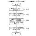
[主制御回路50aのメインフローチャート]
図28を参照して、主制御回路50aで実行される主処理の説明を行う。[Main Flowchart of
With reference to FIG. 28, the main process executed by the
ステップS101では、電源投入時の各種初期化処理を行う。主制御回路50a(図5参照)は、RAM52(図5参照)に記憶される各種変数(通常画面選択カウンタなど)の初期化等を行う。 In step S101, various initialization processes are performed when the power is turned on. The
次に、ステップS102では、通常画面選択処理を行う。この処理の詳細は、後述する図30の通常画面選択処理の詳細で説明する。 Next, in step S102, normal screen selection processing is performed. Details of this processing will be described in details of the normal screen selection processing of FIG. 30 described later.
次に、ステップS103では、BET受付処理を行う。遊技者により、1−BETスイッチ59(図5参照)、3−BETスイッチ60(図5参照)、5−BETスイッチ61(図5参照)の各種BETスイッチが操作されることによってBET操作がなされたことを主制御回路50aが検知したか否かの判定を行う。この判定がYESのときステップS104へ処理を移し、NOのときステップS103を繰り返す。 Next, in step S103, a BET acceptance process is performed. A BET operation is performed by the player operating various BET switches such as a 1-BET switch 59 (see FIG. 5), a 3-BET switch 60 (see FIG. 5), and a 5-BET switch 61 (see FIG. 5). It is determined whether or not the
次に、ステップS104では、スピンスイッチ58(図5参照)またはスタートスイッチ57(図5参照)がONされたか否かの判定を行う。主制御回路50aが、スピンスイッチ58またはスタートスイッチ57がONされたか否かを判定する。この判定がYESのときステップS105へ処理を移し、NOのときステップS104を繰り返す。 Next, in step S104, it is determined whether or not the spin switch 58 (see FIG. 5) or the start switch 57 (see FIG. 5) is turned on. The
次に、ステップS105では、プログレッシブ値の送信処理を行う。主制御回路50aは、ステップS103で受付けられたBET数のうちの所定の割合をプログレッシブ値として、プログレッシブI/F81(図5参照)を介してプログレッシブユニット83へ送信する。 Next, in step S105, a progressive value transmission process is performed. The
次に、ステップS106では、リール22L,22C,22R(図5参照)に停止させるシンボルを確率抽選で決定する処理を行う。主制御回路50aは、乱数サンプリング回路56(図5参照)を制御して乱数発生器55(図5参照)が発生する乱数値から、リール22L,22C,22Rそれぞれに対応する乱数値を、合計3つ抽出する。さらに主制御回路50aは、それぞれの乱数値に基づき、図8に示す通常ゲーム用の、リール22L,22C,22Rそれぞれの確率抽選テーブルを参照して、各リール22L,22C,22Rの停止シンボルを決定する。決定された停止シンボルは、図4に示すそれぞれのシンボルに対応するコードナンバーがRAM52に記憶される。 Next, in step S106, processing for determining symbols to be stopped on the
次に、ステップS107では、リール回転処理を行う。主制御回路50aは、モータ駆動回路67(図5参照)を制御して、ステッピングモータ68L,68C,68Rの駆動を開始することによって、リール22L,22C,22Rの回転を開始させる。 Next, in step S107, reel rotation processing is performed. The
次に、ステップS108では、リール22Rに停止するシンボルがボーナストリガーシンボルかの判定処理を行う。主制御回路50aは、RAM52に記憶されるリールのコードナンバーを参照して、リール22Rに停止させるシンボルがボーナストリガーシンボル93(すなわち、コードナンバーが“02”(図4参照))か否かの判定を行う。この判定がYESのとき図29のステップS109へ処理を移し、NOのとき図29のステップS116へ処理を移す。 Next, in step S108, it is determined whether the symbol stopped on the
次に、ステップS109では、リール停止順序決定処理を行う。主制御回路50aは、乱数サンプリング回路56(図5参照)を制御して、乱数発生器55(図5参照)が発生する乱数値から一の乱数値を抽出する。さらに主制御回路50aは、その乱数値に基づき、図12に示すリール停止順序決定確率抽選テーブルを参照して、各リール22L,22C,22Rの停止順序を決定する。決定されたリール22L,22C,22Rの停止順序は、RAM52に記憶される。 Next, in step S109, a reel stop order determination process is performed. The
次に、ステップS110では、入賞役判定処理を行う。主制御回路50aは、ステップS106でRAM52に記憶されている、リール22L,22C,22Rのそれぞれに停止させるシンボルのコードナンバーを基に、図10に示す入賞役判定テーブルを参照して、停止させるシンボルの組合せが、どの入賞役に該当するかの判定を行う。 Next, in step S110, a winning combination determination process is performed. The
次に、ステップS111では、入賞役は“ハズレ”以外かの判定処理を行う。主制御回路50aは、ステップS110で判定された入賞役が“ハズレ”以外かの判定を行う。この判定がYESのときステップS112へ処理を移し、NOのときステップS113へ処理を移す。 Next, in step S111, it is determined whether the winning combination is other than “losing”. The
次にステップS112では、“入賞役に応じた演出およびリール停止処理”を行う。この処理の詳細は、後述する“入賞役に応じた演出およびリール停止処理”の詳細で説明する。この処理が終了すると、図28のメインフローのステップS102へ処理を移す。 Next, in step S112, “production according to winning combination and reel stop processing” are performed. The details of this processing will be described in detail in the “production according to winning combination and reel stop processing” described later. When this process ends, the process moves to step S102 in the main flow of FIG.
一方、ステップS113では、“リール停止順序は第1停止順序か”の判定を行う。主制御回路50aは、ステップS109で決定され、RAM52に記憶させられたリール停止順序を参照し、このリール停止順序が第1停止順序か否かの判定を行う。この判定がYESのときステップS114へ処理を移し、NOのときステップS115へ処理を移す。 On the other hand, in step S113, it is determined whether the reel stop order is the first stop order. The
次に、ステップS114では、“第1停止順序における失敗演出およびリール停止処理”を行う。この処理の詳細は、後述する“第1停止順序における失敗演出およびリール停止処理”の詳細で説明する。この処理が終了すると、図28のメインフローのステップS102へ処理を移す。 Next, in step S114, “failure effect and reel stop process in first stop order” is performed. Details of this process will be described in detail in “failure effect and reel stop process in first stop order” described later. When this process ends, the process moves to step S102 in the main flow of FIG.
一方、ステップS115では、“第1停止順序以外における失敗演出およびリール停止処理”を行う。この処理の詳細は、後述する“第1停止順序以外における失敗演出およびリール停止処理”の詳細で説明する。この処理が終了すると、図28のメインフローのステップS102へ処理を移す。 On the other hand, in step S115, “failure effect and reel stop processing in other than the first stop order” is performed. Details of this processing will be described in detail in “failed effects and reel stop processing other than in the first stop order” described later. When this process ends, the process moves to step S102 in the main flow of FIG.
一方、ステップS116では、ボーナスゲーム処理を行う。この処理の詳細は、後述するボーナスゲーム処理の詳細で説明する。この処理が終了すると、図28のメインフローのステップS102へ処理を移す。 On the other hand, in step S116, bonus game processing is performed. Details of this processing will be described in details of bonus game processing described later. When this process ends, the process moves to step S102 in the main flow of FIG.
[通常画面選択処理の詳細]
図30を参照して、図28のメインフローのステップS102で実行される通常画面選択処理の詳細を説明する。通常画面とは、スロットマシン1の通常ゲーム時においてメインディスプレイ4に表示される演出画面を指す。[Details of normal screen selection processing]
Details of the normal screen selection process executed in step S102 of the main flow in FIG. 28 will be described with reference to FIG. The normal screen refers to an effect screen displayed on the
ステップS121では、通常画面選択カウンタが“0”か否かの判定を行う。主制御回路50a(図5参照)は、RAM52(図5参照)に記憶されている変数である通常画面選択カウンタの値を参照して、その値が“0”か否かの判定を行う。この判定がYESのときステップS122へ処理を移し、NOのときステップS124へ処理を移す。 In step S121, it is determined whether or not the normal screen selection counter is “0”. The
次に、ステップS122では、通常画面選択抽選処理を行う。主制御回路50aは、乱数サンプリング回路56(図5参照)を制御して乱数発生器55(図5参照)が発生する乱数値から一の乱数値を抽出する。さらに主制御回路50aは、その乱数値に基づき、図11に示す通常画面選択確率テーブルを参照して通常画面を決定する。 Next, in step S122, a normal screen selection lottery process is performed. The
次に、ステップS123では、通常画面切替え処理を行う。主制御回路50aは、ステップS122で決定された、通常ゲーム時においてメインディスプレイ4に表示される通常画面の表示を開始する。主制御回路50aは、副制御回路171(図6参照)に対して、ステップS122で決定された通常画面に対応する演出コマンド(図20参照)を送信し、その演出コマンドを受信した副制御回路171は、その演出コマンドに対応する演出データ(図20参照)をサブROM223(図6参照)から読出し、サブCPU221(図6参照)が画像表示制御回路75を制御して、該当する通常画面をメインディスプレイ4に表示させる。なお、図42は、通常画面としてメインディスプレイ4に“海”を表示するイメージである。また、図43は、通常画面としてメインディスプレイ4に“砂漠”を表示するイメージである。 Next, in step S123, a normal screen switching process is performed. The
次に、ステップS124では、通常画面選択カウンタに1を加算する処理を行う。主制御回路50aは、RAM52に記憶される変数である通常画面選択カウンタに“1”を加算する。 Next, in step S124, a process of adding 1 to the normal screen selection counter is performed. The
次に、ステップS125では、通常画面選択カウンタが“10”に等しいか否かを判定する処理を行う。主制御回路50aは、RAM52に記憶される変数である通常画面選択カウンタを参照し、その値が“10”に等しいか否かを判定する。この判定がYESのときステップS126へ処理を移し、NOのとき本サブルーチンを終了し、図28のステップS103へ処理を移す。 Next, in step S125, a process for determining whether or not the normal screen selection counter is equal to “10” is performed. The
次に、ステップS126では、通常画面選択カウンタをクリアする処理を行う。主制御回路50aは、RAM52に記憶される変数である通常画面選択カウンタに“0”をセット(クリア)する。この処理が終了すると本サブルーチンを終了し、図28のステップS103へ処理を移す。 Next, in step S126, processing for clearing the normal screen selection counter is performed. The
[ボーナスゲーム処理の詳細]
図31,図32を参照して、図29のステップS116で実行されるボーナスゲーム処理の詳細を説明する。[Details of bonus game processing]
Details of the bonus game process executed in step S116 of FIG. 29 will be described with reference to FIGS.
図31のステップS131では、ボーナスゲーム演出選択処理を行う。主制御回路50aは、乱数サンプリング回路56(図5参照)を制御して、乱数発生器55(図5参照)が発生する乱数値から一の乱数値を抽出する。さらに主制御回路50aは、その乱数値に基づき図13に示すボーナスゲーム演出選択確率抽選テーブルを参照して、「望遠鏡演出」を行うか「鳥演出」を行うか、あるいは「イルカ(ヘビ)演出」を行うかを決定する。なお、BET数が5でないときには、この抽選は実行されず、無条件で「望遠鏡演出」を行うと決定する。 In step S131 of FIG. 31, bonus game effect selection processing is performed. The
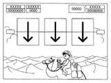
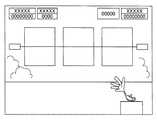
次に、ステップS132では、ステップS131で選択された演出に該当する演出開始コマンドを送信する処理を行う。主制御回路50aは、副制御回路171(図6参照)に対して、ステップS131で決定された演出に対応する演出開始コマンド(「望遠鏡演出開始コマンド」、「鳥演出開始コマンド」、「イルカ演出コマンド1」あるいは「ヘビ演出コマンド1」(図25参照))を送信し、その演出コマンドを受信した副制御回路171は、その演出コマンドに対応する演出データ(図25参照)をサブROM223(図6参照)から読出し、サブCPU221(図6参照)が画像表示制御回路75を制御して、該当する演出画面をメインディスプレイ4に表示させる。なお、図69は、「望遠鏡演出開始コマンド」に対応する「「何かを発見」演出データ」(図25参照)に基づきメインディスプレイ4に表示される演出画面のイメージである。また、図76は、「鳥演出開始コマンド」に対応する「背景が夜になって、鳥出現演出データ」に基づきメインディスプレイ4に表示される演出画面のイメージである。また、図44は、「イルカ演出コマンド1」に対応する「イルカ左表示窓付近出現演出データ」(図25参照)に基づきメインディスプレイ4に表示される演出画面のイメージである。 Next, in step S132, processing for transmitting an effect start command corresponding to the effect selected in step S131 is performed. The
次に、ステップS133では、リール22Lの停止処理を行う。主制御回路50aは、モータ駆動回路67(図5参照)を制御して、図28のステップS106でRAM52(図5参照)に記憶されたリール22Lの停止シンボルの情報を基に、リール22Lの停止処理を行う。 Next, in step S133, the
次に、ステップS134では、左表示窓消去演出コマンド送信処理を行う。主制御回路50aは、副制御回路171に対して、ステップS131で決定された演出に対応する左表示窓消去コマンド(「望遠鏡左表示窓消去コマンド」、「鳥演出左表示窓消去コマンド」、「イルカ演出コマンド2」(図25参照))を送信し、その演出コマンドを受信した副制御回路171は、その演出コマンドに対応する演出データ(図25参照)をサブROM223(図6参照)から読出し、サブCPU221(図6参照)が画像表示制御回路75を制御して、左表示窓23を消去させる。なお、図70は、「望遠鏡左表示窓消去コマンド」に対応する「望遠鏡左表示窓消去演出データ」に基づきメインディスプレイ4において、キャラクタ(召使)が左表示窓23を消去するイメージである。また、図77は、「鳥演出左表示窓消去コマンド」に対応する「鳥演出左表示窓消去演出データ」に基づきメインディスプレイ4において、キャラクタ(召使)が左表示窓23を消去するイメージである。 Next, in step S134, left display window erasing effect command transmission processing is performed. The
次に、ステップS135では、ステップS133と同様の処理により、リール22Cの停止処理を行う。 Next, in step S135, the
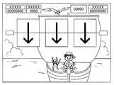
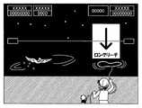
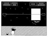
次に、ステップS136では、中表示窓消去演出コマンド送信処理を行う。「望遠鏡中表示窓消去コマンド」、「鳥演出中表示窓消去コマンド」、「イルカ演出コマンド3」(図25参照)に基づき、ステップS134と同様の処理を行う。なお、図45は、「イルカ演出コマンド3」に対応する「イルカ中表示窓付近出現および中表示窓消去演出データ」に基づき、メインディスプレイ4において左表示窓23が消去されたイメージである。また、図70は、「望遠鏡中表示窓消去コマンド」に対応する「望遠鏡中表示窓消去演出データ」に基づきメインディスプレイ4において、キャラクタ(召使)が中表示窓24を消去するイメージである。また、図77は、「鳥演出左表示窓消去コマンド」に対応する「鳥演出左表示窓消去演出データ」に基づきメインディスプレイ4において、キャラクタ(召使)が中表示窓24を消去するイメージである。さらに、図71および図78は、メインディスプレイ4において左表示窓と中表示窓が消去された後に、リール22Rが回転する様子のイメージである。 Next, in step S136, middle display window erasing effect command transmission processing is performed. Based on the “display window erasing command during telescope”, “display window erasing command during bird effect”, and “
次に、ステップS137では、リール22Rのナッジを行うか否かの抽選処理を行う。主制御回路50aは、乱数サンプリング回路56(図5参照)を制御して乱数発生器55(図5参照)が発生する乱数値から一の乱数値を抽出する。さらに主制御回路50aは、その乱数値に基づき、図14に示す“ボーナストリガーシンボル選択時のナッジ演出決定確率抽選テーブル”を参照してナッジを行うか否かを決定する。なお、BET数が5でないときには、無条件でナッジは行わないと決定する。 Next, in step S137, a lottery process for determining whether or not to nudge the
次に、ステップS138では、リール22Rのナッジを行うか否かの判定を行う。主制御回路50aは、ステップS137で決定された決定結果に基づき、リール22Rのナッジを行うか否かの判定を行う。この判定がYESのときステップS139へ処理を移し、NOのときステップS148へ処理を移す。 Next, in step S138, it is determined whether or not to nudge the
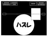
次に、ステップS139では、ナッジ演出コマンド送信処理を行う。主制御回路50aは、副制御回路171に対して、ステップS131で決定された演出に対応するボーナス獲得失敗コマンド(「BANDIT’S HIDEOUT BONUS獲得失敗演出コマンド」、「FORTUNE ISLAND BONUS獲得失敗コマンド」、「イルカ演出コマンド6」または「ヘビ演出コマンド6」(図25参照))を送信し、その演出コマンドを受信した副制御回路171は、その演出コマンドに対応する演出データ(図25参照)をサブROM223(図6参照)から読出し、サブCPU221(図6参照)が画像表示制御回路75を制御して、該当する演出画面を表示する。なお、図73は、「BANDIT’S HIDEOUT BONUS獲得失敗演出コマンド」に対応する「BANDIT’S HIDEOUT BONUS獲得失敗演出データ」に基づきメインディスプレイ4において、ボーナス獲得失敗を遊技者に報知するイメージである。また、図80は、「FORTUNE ISLAND BONUS獲得失敗コマンド」に対応する「FORTUNE ISLAND BONUS獲得失敗演出データ」に基づきメインディスプレイ4において、ボーナス獲得失敗を遊技者に報知するイメージである。 Next, in step S139, a nudge effect command transmission process is performed. The
次に、ステップS140では、リール22Rを所定コマ数移動させて停止処理を行う。主制御回路50aは、モータ駆動回路67を制御して、図28のステップS106でRAM52(図5参照)に記憶されたリール22Rの停止シンボルの情報を基に、所定コマ数(例えば1コマ(すなわち、シンボル1つ分)とするが、本発明はこれに限定されない)移動させてリール22Rの停止処理を行う。この結果、リール22Rの停止シンボルは、ステップS106でRAM52(図5参照)に記憶されたコードナンバーに対応するシンボルに対して1つ前のコードナンバーのシンボルまたは1つ後のコードナンバーのシンボルとなる。 Next, in step S140, the
次に、ステップS141では、ボーナス逆転成功演出コマンド送信処理を行う。主制御回路50aは、副制御回路171に対して、ステップS131で決定された演出に対応するボーナス逆転獲得コマンド(「鳥飛来演出コマンド」、「鳥再飛来コマンド」、「イルカ演出コマンド7」または「ヘビ演出コマンド7」(図25参照))を送信し、その演出コマンドを受信した副制御回路171は、その演出コマンドに対応する演出データ(図25参照)をサブROM223(図6参照)から読出し、サブCPU221(図6参照)が画像表示制御回路75を制御して、該当する演出画面を表示する。なお、図74は、「鳥飛来演出コマンド」に対応する「鳥飛来演出データ」に基づきメインディスプレイ4において、ボーナス逆転獲得を遊技者に示唆するイメージである。また、図81は、「鳥再飛来コマンド」に対応する「鳥再飛来演出データ」に基づきメインディスプレイ4において、ボーナス逆転獲得を遊技者に示唆するイメージである。 Next, in step S141, bonus reversal success effect command transmission processing is performed. The
次に、ステップS142では、リール22Rを再び回転させる処理を行う。主制御回路50aは、モータ駆動回路67(図5参照)を制御して、ステッピングモータ68Rの駆動を開始することによって、リール22Rの回転を再開させる。 Next, in step S142, the
次に、ステップS143では、待ち時間消化処理を行う。主制御回路50aは、一定時間ウェイト状態になり、ステップS142で開始されたリール22Rの回転を維持する。 Next, in step S143, waiting time digestion processing is performed. The
次に、ステップS144では、図31のステップS133と同様の処理により、リール22Rの停止処理を行う。このようにして、リール22Rにボーナストリガーシンボル93が停止する。 Next, in step S144, the
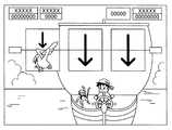
次に、ステップS145では、演出はイルカ成功演出またはヘビ成功演出か否かの判定処理を行う。主制御回路50aは、ステップS191で決定された演出が、イルカ成功演出またはヘビ成功演出か否かの判定を行う。この判定がYESのときステップS146へ処理を移し、NOのときステップS147へ処理を移す。なお、図47は、第3番目の停止リールがリール22Rであり、「成功演出」が「イルカ成功演出」であり、このステップS145の判定においてYESと判定されたときに表示される演出表示のイメージである。 Next, in step S145, it is determined whether or not the effect is a dolphin success effect or a snake success effect. The
次に、ステップS146では、MAGIC LAMP BONUS処理を行う。この処理の詳細は、後述する図36〜図37のMAGIC LAMP BONUS処理の詳細で説明する。この処理が終了すると本サブルーチンは終了し、図28のステップS102へ処理を移す。 Next, in step S146, MAGIC LAMP BONUS processing is performed. Details of this processing will be described in details of the MAGIC LAMP BONUS processing of FIGS. When this process ends, this subroutine ends, and the process proceeds to step S102 in FIG.
一方、ステップS147では、FORTUNE ISLAND BONUS獲得演出コマンド送信処理を行う。主制御回路50aは、副制御回路171に対して、鳥演出に対応するボーナス獲得コマンド(「FORTUNE ISLAND BONUS獲得演出コマンド(図25参照)」)を送信し、その演出コマンドを受信した副制御回路171は、その演出コマンドに対応する演出データ(図25参照)をサブROM223(図6参照)から読出し、サブCPU221(図6参照)が画像表示制御回路75を制御して、該当する演出画面を表示する。なお、図75、図79および図82は、「FORTUNE ISLAND BONUS獲得演出コマンド」に対応する「FORTUNE ISLAND BONUS獲得演出データ」に基づき、メインディスプレイ4において、ボーナス獲得を遊技者に報知するイメージである。図75は「望遠鏡演出」から逆転して獲得されるFORTUNE ISLAND BONUSのボーナス獲得を遊技者に報知するイメージである。図79は「鳥演出」からナッジ演出なしで獲得されるFORTUNE ISLAND BONUSのボーナス獲得を遊技者に報知するイメージである。図82は「鳥演出」からナッジ演出を経て獲得されるFORTUNE ISLAND BONUSのボーナス獲得を遊技者に報知するイメージである。 On the other hand, in step S147, FORTUNE ISLAND BONUS acquisition effect command transmission processing is performed. The
次に、ステップS148では、FORTUNE ISLAND BONUS開始コマンド送信処理を行う。主制御回路50aは、副制御回路171に対して、FORTUNE ISLAND BONUS開始コマンドを送信する。このFORTUNE ISLAND BONUS開始コマンドを受信した副制御回路171は、後述する図33のFORTUNE ISLAND BONUS開始コマンド受信処理を実行する。 Next, in step S148, FORTUNE ISLAND BONUS start command transmission processing is performed. The
次に、ステップS149では、FORTUNE ISLAND BONUS終了コマンド受信処理を行う。主制御回路50aは、副制御回路171から送信されてくるFORTUNE ISLAND BONUS終了コマンドを受信する。このFORTUNE ISLAND BONUS終了コマンドを受信した主制御回路50aは、本サブルーチンを終了し、図28のメインフローのステップS102へ処理を移す。 Next, in a step S149, FORTUNE ISLAND BONUS end command reception processing is performed. The
一方、ステップS150では、ボーナスゲーム演出は望遠鏡演出か否かの判定を行う。主制御回路50aは、ステップS131で決定されたボーナスゲーム演出が望遠鏡演出か否かの判定を行う。この判定がYESのときステップS149へ処理を移し、NOのときステップS143へ処理を移す。 On the other hand, in step S150, it is determined whether the bonus game effect is a telescope effect. The
次に、ステップS151では、図31のステップS133と同様の処理により、リール22Rの停止処理を行う。このようにして、リール22Rにボーナストリガーシンボル93が停止する。 Next, in step S151, the
次に、ステップS152では、BANDIT’S HIDEOUT BONUS獲得演出コマンド送信処理を行う。「BANDIT’S HIDEOUT BONUS獲得演出コマンド(図25参照)」に基づく以外は、ステップS147と同様の処理を行う。なお、図72は、「BANDIT’S HIDEOUT BONUS獲得演出コマンド」に対応する「BANDIT’S HIDEOUT BONUS獲得演出データ」に基づき、メインディスプレイ4において、ボーナス獲得を遊技者に報知するイメージである。 Next, in step S152, BANDIT'S HIDEOUT BONUS acquisition effect command transmission processing is performed. Except based on the “BANDIT ’S HIDEOUT BONUS acquisition effect command (see FIG. 25)”, the same processing as step S147 is performed. FIG. 72 is an image in which the player is notified of the bonus acquisition on the
次に、ステップS153では、BANDIT’S HIDEOUT BONUS開始コマンド送信処理を行う。主制御回路50aは、副制御回路171に対して、BANDIT’S HIDEOUT BONUS開始コマンドを送信する。このBANDIT’S HIDEOUT BONUS開始コマンドを受信した副制御回路171は、後述する図34のBANDIT’S HIDEOUT BONUS開始コマンド受信処理を実行する。 Next, in step S153, BANDIT'S HIDEOUT BONUS start command transmission processing is performed. The
次に、ステップS154では、BANDIT’S HIDEOUT BONUS終了コマンド受信処理を行う。主制御回路50aは、副制御回路171から送信されてくるBANDIT’S HIDEOUT BONUS終了コマンドを受信する。このBANDIT’S HIDEOUT BONUS終了コマンドを受信した主制御回路50aは、本サブルーチンを終了し、図28のメインフローのステップS102へ処理を移す。 Next, in step S154, BANDIT'S HIDEOUT BONUS end command reception processing is performed. The
[FORTUNE ISLAND BONUS開始コマンド受信処理の詳細]
図33は、図31のボーナスゲーム処理のステップS146で、主制御回路50a(図5参照)が送信してきたFORTUNE ISLAND BONUS開始コマンドを副制御回路171(図6参照)が受信したときに、副制御回路171で実行される処理である。この処理は、すなわち、FORTUNE ISLAND BONUSの処理である。[Details of FORTUNE ISLAND BONUS start command reception processing]
FIG. 33 shows a case where the sub control circuit 171 (see FIG. 6) receives the FORTUNE ISLAND BONUS start command transmitted by the
FORTUNE ISLAND BONUSは、すごろく遊技を模したボーナスゲームである。サブディスプレイ3にすごろく盤を表示し、メインキャラクタがすごろく盤の区画を進んでいくことによって遊技が進行する。メインキャラクタがすごろく盤において進む区画の数は、遊技者が、メインディスプレイ4に表示される3つのサイコロから1つを選択し、そのサイコロが変動表示して最終的に表示した出目の数によって決まる。サイコロに最終的表示される出目は、変動表示が開始した後に、3つのサイコロそれぞれで出目の出現確率が異なる確率抽選によって決められる。その出目は、初めは遊技者に対して不可視であるが、遊技者が任意に1つのサイコロを選択してそのサイコロが変動表示し、最終的に変動表示が停止したときに出目が分かるようになるように構成する。なお、サイコロの選択の指定は、タッチパネル方式による。遊技者が任意の1つのサイコロの表示にタッチすることによってタッチパネル30がそのタッチを検知し、検知信号をタッチパネル制御回路76(図6参照)に送信することによって、副制御回路171(図6参照)は、画像表示が遊技者によりタッチされたことを認識する。なお、以上説明した、メインディスプレイ4に表示されるサイコロとその出目の制御は、適宜設計変更可能事項であり、液晶表示装置とタッチパネルとの組合せで、予めランダムに決定されたサイコロの出目を、遊技者による操作を受付けることを契機として遊技者に表示する方式であれば、いずれの方式であってもよい。図91の下方の図の表示501が、前述のサイコロのイメージである。 FORTUNE ISLAND BONUS is a bonus game that imitates the game. The sub-display 3 displays the sugoroku board, and the game progresses as the main character advances through the section of the sugoroku board. The number of sections that the main character advances on the sugoroku board depends on the number of outcomes that the player has selected from the three dice displayed on the
また、FORTUNE ISLAND BONUSにおいて、メインキャラクタは5つのライフポイントを持って遊技を開始する。ライフポイントは、すごろく盤の区画を進み、様々なイベントに遭遇することによって増加したり減少したりする。そして、最終地点で全てのFORTUNE ISLAND BONUSのゲームが終了したときに、ライフポイントが“0”でなければ、遊技者は特別配当としてジャックポットを獲得できる。メインキャラクタがすごろく盤の最終地点に到達する前に、ライフポイントが“0”となると、その時点でFORTUNE ISLAND BONUSは終了する。 In FORTUNE ISLAND BONUS, the main character starts playing with 5 life points. Lifepoints can be increased or decreased by going through a lot of board sections and encountering various events. When all FORTUNE ISLAND BONUS games are completed at the final point, if the life point is not “0”, the player can win a jackpot as a special payout. If the life point becomes “0” before the main character reaches the final point of the sugoroku board, FORTUNE ISLAND BONUS ends at that point.
以下、メインディスプレイ4において、遊技者が何らかの入力操作を入力する方式は、表示画像を選択してタッチし、タッチパネル30がそのタッチを検知し、検知信号をタッチパネル制御回路76に送信することによって、副制御回路171は、画像表示が遊技者によりタッチされたことを認識する、タッチパネル方式とする。 Hereinafter, in the
ステップS153では、初期画面表示処理を行う。副制御回路171はサブROM223(図6参照)に格納されているFORTUNE ISLAND BONUS演出データテーブル(図27参照)からFORTUNE ISLAND BONUS開始演出コマンドを読み出してサブCPU221に対して送信し、その演出コマンドを受信したサブCPU221がFORTUNE ISLAND BONUS演出データテーブルを参照して、FORTUNE ISLAND BONUS開始演出コマンドに対応する演出データを読み出し、メインディスプレイ4に、対応する演出画像を表示する。図90は、その初期画面のイメージである。なお、初期画面のサブディスプレイ3には、「神殿(ANCIENT TEMPLE)」、「深いジャングル(DEEP JUNGLE)」、「秘密の洞窟(SECRET CAVE)」、「岩場(ROCKY STRTCH)」が表示されるが、これは、遊技者が「深いジャングル」、「秘密の洞窟」、「岩場」のいずれかのルートを選択して、「神殿」に至ることを意味している。ルートの選択は、図90の下方図のメインディスプレイ4の表示において、遊技者が「JUNGLE」、「CAVE」、「ROCKY」と表示された表示画像500のいずれかにタッチすることによって、それぞれのルートに対応するすごろく盤が選択されて表示される。それらのうちのいずれかを選択することによって、副制御回路171はサブROM223(図6参照)に格納されているFORTUNE ISLAND BONUS演出データテーブル(図27参照)からマップ画像コマンド(「DEEP JUNGLEマップ画像コマンド」、「SECRET CAVEマップ画像コマンド」、「ROCKY STRTCHマップ画像コマンド」)を読み出してサブCPU221に対して送信し、その演出コマンドを受信したサブCPU221がFORTUNE ISLAND BONUS演出データテーブルを参照して、FORTUNE ISLAND BONUS開始演出コマンドに対応する演出データを読み出し、メインディスプレイ4に、対応する演出画像を表示する。図91は、遊技者により「岩場(ROCKY STRTCH)」が選択されて、そのすごろく盤が表示されるイメージである。 In step S153, an initial screen display process is performed. The
また、「岩場(ROCKY STRTCH)」のすごろく盤には、スタート地点からゴール地点である「神殿」に至るまで、6つの区画がある。スタート地点に近いほうから、「宝箱」、「岩石」、「大蛇」、「宝箱」、「宝箱」、「大蜘蛛」の区画である。それぞれの区画において、様々なイベントが発生するが、その詳細は、ステップS162の説明で行う。 In addition, there are six sections on the "ROCKY STRTCH" Sugoroku board from the starting point to the goal point "Shrine". From the side closer to the starting point, it is a section of “treasure chest”, “rock”, “large snake”, “treasure chest”, “treasure chest”, and “large coral”. Various events occur in each section, and details thereof will be described in the description of step S162.
次に、ステップS154では、サイコロ選択受付処理を行う。メインディスプレイ4に表示された3つのサイコロ画像のうち、任意の1つが遊技者によりタッチされ、そのタッチをタッチパネル30が検知し、検知信号をタッチパネル制御回路76に送信することによって、副制御回路171は、表示が遊技者によりタッチされたことを認識する。 Next, in step S154, a dice selection acceptance process is performed. An arbitrary one of the three dice images displayed on the
次に、ステップS155では、サイコロ抽選処理を行う。副制御回路171は、ソフトウェア制御により一の乱数値を選択し、その乱数値に基づき、遊技者によりタッチされ選択されたサイコロ画像に対応する出目の確率抽選テーブル(図示せず)を参照して、サイコロの最終出目を決定する。そして、副制御回路171は、画像表示制御回路75を制御してサイコロ画像の変動表示を開始し、しばらくしてその変動表示を停止する。その変動表示が停止したときに、サイコロの最終出目が表示される。すなわち、サイコロの最終出目は予め決定され、この段階ではそのサイコロの最終出目は遊技者に対して表示されないが、その後サイコロ画像の変動表示を行い、その変動表示が停止したときに初めて、サイコロの最終出目が遊技者に対して表示される。 Next, in step S155, a dice lottery process is performed. The
次に、ステップS156では、ステップS155で決定されたサイコロの最終出目の数だけ、サブディスプレイ3に表示されるメインキャラクタが、すごろく盤の区画を進む処理を行う。副制御回路171は、ステップS155で決定されたサイコロの最終出目の数に基づき、画像表示制御回路74を制御して、サブディスプレイ3に表示されるメインキャラクタにすごろく盤の区画を進ませる。 Next, in step S156, the main character displayed on the
次に、ステップS157では、メインキャラクタが最終地点に到達したかの判定処理を行う。副制御回路171は、メインキャラクタがすごろくのゴールである「神殿」に到達したかの判定を行う。この判定がYESのときステップS158へ処理を移し、NOのときステップS162へ処理を移す。 Next, in step S157, it is determined whether or not the main character has reached the final point. The
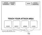
次に、ステップS158では、最終地点でのイベント発生処理を行う。副制御回路171は、画像表示制御回路74を制御して、サブディスプレイ3に表示されるメインキャラクタに、「神殿」の主である「鬼」との対決(神殿バトル)を行わせる。副制御回路171はサブROM223(図6参照)に格納されているFORTUNE ISLAND BONUS演出データテーブル(図27参照)から神殿演出画像コマンドを読み出してサブCPU221に対して送信し、その演出コマンドを受信したサブCPU221がFORTUNE ISLAND BONUS演出データテーブルを参照して、神殿演出画像コマンドに対応する演出データを読み出し、メインディスプレイ4に対応する演出画像を表示する。図103は、サブディスプレイ3におけるメインキャラクタと「鬼」との対決のイメージである。図104は、図103の画面と同時にメインディスプレイ4に表示される、メインキャラクラが「鬼」を攻撃するポイントを選択させる表示画面である。この選択は、前述のようにタッチパネル方式により。「HEAD」、「BODY」、「ARMS」、「LEGS」の4つの攻撃ポイント(表示画像502)から攻撃ポイントを選択する。その攻撃の成否は、表示画像502のいずれかが選択されたときに、副制御回路171がソフトウェア制御により一の乱数値を選択し、その乱数値に基づき、遊技者によりタッチされ選択された攻撃ポイントに対応する、攻撃の成否を決定する確率抽選テーブル(図示せず)を参照して、攻撃の成否が決定される。なお、メインキャラクラと「鬼」は交互に攻撃を繰り返し、攻撃が成功したときには、相手のライフポイント(図103で示される5つのハートのマーク)が1つ減少する。先に相手のライフポイントを“0”とさせた方が、神殿バトルでの勝利者である。図105は、メインキャラクタが「鬼」のライフポイントを“0”としたことによって神殿バトルに勝利したときに、サブディスプレイ3に表示される表示画像のイメージである。図106は、メインキャラクタのライフポイントが“0”となったことによって神殿バトルに敗北したときに、サブディスプレイ3に表示される表示画像のイメージである。ただし、図107に示すように、副制御回路171における所定の抽選に当選した場合、メインキャラクタが「鬼」に敗北しても、鳥が現れてメインキャラクタを救い、メインキャラクタのライフポイントが1だけ回復することによって、再び「鬼」との戦いを行うことができる逆転演出がある。以上示した画像は、全て所定のデータとして、FORTUNE ISLAND BONUS演出データテーブルに格納されている。 Next, in step S158, event generation processing at the final point is performed. The
次に、ステップS159では、メインキャラクタが最終地点でのイベントで勝利したか否かの判定処理を行う。副制御回路171は、ステップS158の処理で、最終的にメインキャラクタが勝利したか否かを判定する。この判定がYESのときステップS160へ処理を移し、NOのときにステップS161へ処理を移す。 Next, in step S159, it is determined whether or not the main character has won the event at the final point. The
次に、ステップS160では、ジャックポット配当処理を行う。副制御回路171は、主制御回路50aに対し、ジャックポット配当要求の信号を送信する。その信号を受信した主制御回路50aは、プログレッシブI/F81を介して、プログレッシブユニット83に対して、ジャックポット配当払出の要求信号を送信する。ジャックポット配当払出の要求信号を受信したプログレッシブユニット83は、所定のプログレッシブ値をジャックポット配当として遊技者に付与する信号を、主制御回路50aに送信する。ジャックポット配当として遊技者に付与する信号を受信した主制御回路50aは、付与されたジャックポット配当に相当するコインの枚数を、スロットマシン1のクレジット値(スロットマシン1に貯留されたコインの枚数)に加算する。 Next, in step S160, jackpot payout processing is performed. The
次に、ステップS161では、FORTUNE ISLAND BONUS終了コマンドを主制御回路50aに送信する処理を行う。副制御回路171は、主制御回路50aに対し、FORTUNE ISLAND BONUS終了コマンドを送信する。また、サブディスプレイ3の表示を配当表示へ復旧する。この処理が終了すると、本ルーチンは終了する。 Next, in step S161, processing for transmitting a FORTUNE ISLAND BONUS end command to the
一方、ステップS162では、“メインキャラクタが止まった各区画でのイベント発生処理”を行う。前述したように、例えば、「神殿(ANCIENT TEMPLE)」に至るルートとして「岩場(ROCKY STRTCH)」が選択されたときには、スタート地点からゴール地点である「神殿」に至るまで、6つの区画がある。スタート地点に近いほうから、「宝箱」、「岩石」、「大蛇」、「宝箱」、「宝箱」、「大蜘蛛」の区画である。 On the other hand, in step S162, “event generation processing in each section where the main character stops” is performed. As mentioned above, for example, when “ROCKY STRTCH” is selected as the route to “ANCIENT TEMPLE”, there are six sections from the starting point to “God” which is the goal point. . From the side closer to the starting point, it is a section of “treasure chest”, “rock”, “large snake”, “treasure chest”, “treasure chest”, and “large coral”.
メインキャラクタが「宝箱」の区画に止まったときには、副制御回路171はサブROM223(図6参照)に格納されているFORTUNE ISLAND BONUS演出データテーブル(図27参照)から宝箱演出画像コマンドを読み出してサブCPU221に対して送信し、その演出コマンドを受信したサブCPU221がFORTUNE ISLAND BONUS演出データテーブルを参照して、FORTUNE ISLAND BONUS開始演出コマンドに対応する演出データを読み出し、メインディスプレイ4に、対応する演出画像を表示する。メインキャラクタが「宝箱」の区画に止まったときには、メインキャラクタのライフポイントは1だけ増加される。 When the main character stops in the “treasure box” section, the
メインキャラクタが「岩石」の区画に止まったときには、副制御回路171はサブROM223(図6参照)に格納されているFORTUNE ISLAND BONUS演出データテーブル(図27参照)から岩石演出画像コマンドを読み出してサブCPU221に対して送信し、その演出コマンドを受信したサブCPU221がFORTUNE ISLAND BONUS演出データテーブルを参照して、FORTUNE ISLAND BONUS開始演出コマンドに対応する演出データを読み出し、対応する演出画像をサブディスプレイ3に表示する。図98は、サブディスプレイ3に表示される、対応する演出画像のイメージである。メインキャラクタが「岩石」を押し止めることができた場合には、メインキャラクタのライフポイントは減少しない(図99参照)。しかし、メインキャラクタが「岩石」を押し止めることがでなかった場合には、メインキャラクタのライフポイントは1減少する(図100参照)。ただし、図101の様に、メインキャラクタのサブキャラクタである「サル」が現れて、メインキャラクタを救い、メインキャラクタのライフポイントの減少を阻止することがある(図102参照)。「サル」が出現するか否かは、副制御回路171におけるソフトウェア制御により選択される一の乱数値に基づき、所定の確率抽選テーブル(図示せず)の参照により決定される。 When the main character stops in the “rock” section, the
メインキャラクタが「大蜘蛛」の区画に止まったときには、副制御回路171はサブROM223(図6参照)に格納されているFORTUNE ISLAND BONUS演出データテーブル(図27参照)から大蜘蛛演出画像コマンドを読み出してサブCPU221に対して送信し、その演出コマンドを受信したサブCPU221がFORTUNE ISLAND BONUS演出データテーブルを参照して、FORTUNE ISLAND BONUS開始演出コマンドに対応する演出データを読み出し、対応する演出画像をサブディスプレイ3に表示する。図92は、サブディスプレイ3に表示される、対応する演出画像のイメージである。メインキャラクタが「大蜘蛛」との戦いに勝利することができた場合には、メインキャラクタのライフポイントは減少しない(図93参照)。しかし、メインキャラクタが「大蜘蛛」との戦いに勝利することができなかった場合には、メインキャラクタのライフポイントは1減少する(図94参照)。ただし、図95の様に、メインキャラクタのサブキャラクタである「サル」が現れて、メインキャラクタの代わりに「大蜘蛛」と戦って(図96参照)、その戦いに勝利してメインキャラクタのライフポイントの減少を阻止することがある(図97参照)。「サル」が出現するか否かは、副制御回路171におけるソフトウェア制御により選択される一の乱数値に基づき、所定の確率抽選テーブル(図示せず)の参照により決定される。 When the main character stops in the section of “Daegu”, the
メインキャラクタが「大蛇」の区画に止まったときには、副制御回路171はサブROM223(図6参照)に格納されているFORTUNE ISLAND BONUS演出データテーブル(図27参照)から大蛇演出画像コマンドを読み出してサブCPU221に対して送信し、その演出コマンドを受信したサブCPU221がFORTUNE ISLAND BONUS演出データテーブルを参照して、FORTUNE ISLAND BONUS開始演出コマンドに対応する演出データを読み出し、サブディスプレイ3に、対応する演出画像を表示する。メインキャラクタが「大蛇」の区画に止まったときのライフポイントの増減の要因は、メインキャラクタが「大蜘蛛」の区画に止まったときと同様である。 When the main character stops in the “large snake” section, the
次に、ステップS163では、メインキャラクタのライフポイントが“0”か否かを判定する。副制御回路171が、メインキャラクタのライフポイントが“0”か否かを判定する。この判定がYESのときステップS161へ処理を移し、NOのときステップS154へ処理を移す。 Next, in step S163, it is determined whether or not the life point of the main character is “0”. The
[BANDIT’S HIDEOUT BONUS開始コマンド受信処理の詳細]
図34は、図31のボーナスゲーム処理のステップS151で、主制御回路50a(図5参照)が送信してきたBANDIT’S HIDEOUT BONUS開始コマンドを副制御回路171(図6参照)が受信したときに、副制御回路171で実行される処理である。この処理は、すなわち、BANDIT’S HIDEOUT BONUSの処理である。[Details of BANDIT'S HIDEOUT BONUS start command reception processing]
FIG. 34 shows a case where the sub control circuit 171 (see FIG. 6) receives the BANDIT'S HIDEOUT BONUS start command transmitted by the
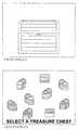
ステップS171では、初期画面表示処理を行う。副制御回路171はサブROM223(図6参照)に格納されているBANDIT’S HIDEOUT BONUS演出データテーブル(図26参照)からBANDIT’S HIDEOUT BONUS開始演出コマンドを読み出してサブCPU221に対して送信し、その演出コマンドを受信したサブCPU221がBANDIT’S HIDEOUT BONUS演出データテーブルを参照して、BANDIT’S HIDEOUT BONUS開始演出コマンドに対応する演出データを読み出し、対応する演出画像をサブディスプレイ3とメインディスプレイ4に表示する。図83は、その初期画面のイメージである。なお、初期画面のサブディスプレイ3には、「宝箱」が表示され、図83の下方図のメインディスプレイ4の表示には、複数の「宝箱」が表示される。遊技者が、それらの「宝箱」うちのいずれかを選択することによってボーナスゲームが進行する。「宝箱」の中身は「財宝」、「ラッキーアイテム」、「ドクロ」の三種類があるが、「宝箱」の中身の決定は、初期画面が表示される処理の過程で、副制御回路171のソフトウェア制御による一の乱数値の選択により、その乱数値に基づき、所定の確率抽選テーブル(図示せず)を参照して、予め決定される。 In step S171, an initial screen display process is performed. The
次に、ステップS172では、宝箱選択受付処理を行う。メインディスプレイ4に表示された複数の「宝箱」のうち、任意の1つが遊技者によりタッチされ、そのタッチをタッチパネル30が検知し、検知信号をタッチパネル制御回路76に送信することによって、副制御回路171は、表示が遊技者によりタッチされたことを認識する。 Next, in step S172, treasure box selection acceptance processing is performed. An arbitrary one of a plurality of “treasure chests” displayed on the
次に、ステップS173では、選択された宝箱を開く演出画像をサブディスプレイ3に表示する処理を行う。副制御回路171はサブROM223(図6参照)に格納されているBANDIT’S HIDEOUT BONUS演出データテーブル(図26参照)から宝箱オープン演出コマンドを読み出してサブCPU221に対して送信し、その演出コマンドを受信したサブCPU221がBANDIT’S HIDEOUT BONUS演出データテーブルを参照して、宝箱オープン演出コマンドに対応する演出データを読み出し、サブディスプレイ3に、対応する演出画像を表示する。図84は、その演出画像のイメージである。 Next, in step S173, processing for displaying an effect image for opening the selected treasure chest on the
次に、ステップS174では、宝箱の中身はドクロか否かの判定を行う。副制御回路171が、宝箱の中身はドクロか否かの判定を行う。この判定がYESのときステップS175へ処理を移し、NOのときステップS178へ処理を移す。 Next, in step S174, it is determined whether or not the contents of the treasure box are skulls. The
次に、ステップS175では、ドクロの演出画像をサブディスプレイ3に表示する処理を行う。副制御回路171はサブROM223(図6参照)に格納されているBANDIT’S HIDEOUT BONUS演出データテーブル(図26参照)から“ドクロ出現演出コマンド”を読み出してサブCPU221に対して送信し、その演出コマンドを受信したサブCPU221がBANDIT’S HIDEOUT BONUS演出データテーブルを参照して、“ドクロ出現演出コマンド”に対応する演出データを読み出し、サブディスプレイ3に、対応する演出画像を表示する。図88は、その演出画像のイメージである。 Next, in step S175, a process of displaying a skull effect image on the
次に、ステップS176では、慌てふためいて逃げ去るメインキャラクタの演出画像をサブディスプレイ3に表示する処理を行う。副制御回路171はサブROM223(図6参照)に格納されているBANDIT’S HIDEOUT BONUS演出データテーブル(図26参照)から“ドクロから逃げるメインキャラクタ演出コマンド”を読み出してサブCPU221に対して送信し、その演出コマンドを受信したサブCPU221がBANDIT’S HIDEOUT BONUS演出データテーブルを参照して、“ドクロから逃げるメインキャラクタ演出コマンド”に対応する演出データを読み出し、サブディスプレイ3に、対応する演出画像を表示する。図89は、その演出画像のイメージである。 Next, in step S176, a process of displaying on the
次に、ステップS177では、BANDIT’S HIDEOUT BONUS終了コマンドを主制御回路50aに送信する処理を行う。副制御回路171は、主制御回路50aに対し、BANDIT’S HIDEOUT BONUS終了コマンドを送信する。また、サブディスプレイ3の表示を配当表示へ復旧する。この処理が終了すると、本ルーチンは終了する。 Next, in step S177, processing for transmitting a BANDIT'S HIDEOUT BONUS end command to the
一方、ステップS178では、“財宝またはラッキーアイテムの演出画像をサブディスプレイに表示し、メインディスプレイに表示される宝箱の演出画像に獲得ポイントなどを表示”する処理を行う。副制御回路171はサブROM223(図6参照)に格納されているBANDIT’S HIDEOUT BONUS演出データテーブル(図26参照)から“財宝出現演出コマンド”または“ラッキーアイテム出現コマンド”を読み出してサブCPU221に対して送信し、その演出コマンドを受信したサブCPU221がBANDIT'S HIDEOUT BONUS演出データテーブルを参照して、“財宝出現演出コマンド”または“ラッキーアイテム出現コマンド”それぞれに対応する演出データを読み出し、対応する演出画像をサブディスプレイ3に表示する。図85および図86は、その演出画像のイメージである。ここで、例えば、50枚のコインを獲得することができた場合には、図85の下方図のメインディスプレイの画面において、50枚のコインが出現した宝箱を識別するために、その宝箱に“50”の表示を付加する。「ラッキーアイテム(その時点で遊技者がクレジットすることによって所持するコインの枚数を2倍にするアイテムなど)」の獲得においても、同様に、「ラッキーアイテム」が出現した宝箱を識別するために、その宝箱に「ラッキーアイテム」の画像表示を付加する。 On the other hand, in step S178, a process of “displaying the effect image of the treasure or lucky item on the sub-display and displaying the acquired points on the effect image of the treasure box displayed on the main display” is performed. The
次に、ステップS179では、財宝またはラッキーアイテムを獲得して喜ぶメインキャラクタの演出画像をサブディスプレイに表示する処理を行う。副制御回路171はサブROM223(図6参照)に格納されているBANDIT'S HIDEOUT BONUS演出データテーブル(図26参照)から“財宝メインキャラクタ演出コマンド”または“ラッキーアイテムメインキャラクタ演出コマンド”を読み出してサブCPU221に対して送信し、その演出コマンドを受信したサブCPU221がBANDIT'S HIDEOUT BONUS演出データテーブルを参照して、財宝メインキャラクタ演出コマンド”または“ラッキーアイテムメインキャラクタ演出コマンド”それぞれに対応する演出データを読み出し、サブディスプレイ3に、対応する演出画像を表示する。図87は、その演出画像のイメージである。 Next, in step S179, processing for displaying an effect image of the main character that is pleased by acquiring a treasure or a lucky item on the sub-display is performed. The
次に、ステップS180では、獲得ポイント加算処理する処理を行う。副制御回路171は、ステップS178で獲得したコインを遊技者のコインのクレジット数に加算する。 Next, in step S180, an acquisition point addition process is performed. The
次に、ステップS181では、所定個数の宝箱が選択されたか否かの判定を行う。副制御回路171が、遊技者により所定個数の宝箱が選択されたか否かの判定を行う。この判定がYESのときステップS177へ処理を移し、NOのときステップS172へ処理を移す。 Next, in step S181, it is determined whether a predetermined number of treasure chests have been selected. The
[入賞役に応じた演出およびリール停止処理の詳細]
図35を参照して、図29のステップS112で実行される、入賞役に応じた演出およびリール停止処理の詳細を説明する。なお、この処理では、入賞役は“ボーナスゲーム”および“ハズレ”以外である。[Details of presentation and reel stop processing according to the winning combination]
With reference to FIG. 35, the details of the effect according to the winning combination and reel stop processing executed in step S112 of FIG. 29 will be described. In this process, the winning combination is other than “bonus game” and “losing”.
ステップS191では、入賞役に応じた演出の確率抽選処理を実行する。主制御回路50a(図5参照)は、乱数サンプリング回路56(図5参照)を制御して、乱数発生器55(図5参照)が発生する乱数値から一の乱数値を抽出する。さらに主制御回路50aは、その乱数値に基づき、ROM51(図5参照)に格納されている、“入賞役(ボーナスゲーム、ハズレを除く)に応じた演出選択確率抽選テーブル”(図15参照)を参照して、各入賞役(ワイルド、赤7、3BAR、2BAR、BAR、ANYBAR)に応じた「成功演出」(イルカ(ヘビ)成功演出、カモメ(ハゲタカ)成功演出、サル成功演出)を決定する。 In step S191, an effect probability lottery process corresponding to the winning combination is executed. The
次に、ステップS192では、“第1番目の停止リールの演出コマンド送信”処理を行う。主制御回路50a(図5参照)が、ステップS191で決定された「成功演出」と図29のステップS109のリール停止順序決定処理で決定された停止順序とに従って、第1番目に停止するリールの演出コマンドを送信する。すなわち、主制御回路50aは、副制御回路171(図6参照)に対して、ステップS191で決定された演出と図29のステップS109のリール停止順序決定処理で決定された停止順序とに対応する「成功演出コマンド」(カモメ演出コマンド1〜3、ハゲタカ演出コマンド1〜3、サル演出コマンド1〜3(図21参照)のそれぞれいずれか)を送信し、その演出コマンドを受信した副制御回路171は、その演出コマンドに対応する演出データ(図21参照)をサブROM223(図6参照)から読出し、サブCPU221(図6参照)が画像表示制御回路75を制御して、該当する演出を実行させる。図49および図50は、第1番目の停止リールがリール22Lであり、「成功演出」が「カモメ成功演出」であるときの演出表示のイメージである。図55は、第1番目の停止リールがリール22Lであり、「成功演出」が「サル成功演出」であるときの演出表示のイメージである。 Next, in step S192, a “first stop reel effect command transmission” process is performed. The
次に、ステップS193では、待ち時間消化処理を行う。主制御回路50aは、所定の時間ウェイト状態となり、ステップS192で実行が指示された演出が完了するまで待機する。 Next, in step S193, waiting time digestion processing is performed. The
次に、ステップS194では、第1番目の停止リール停止処理を行う。主制御回路50aは、モータ駆動回路67(図5参照)を制御して、図28のステップS106でRAM52(図5参照)に記憶された第1番目の停止リールの停止シンボルの情報を基に、第1番目の停止リールの停止処理を行う。 Next, in step S194, a first stop reel stop process is performed. The
次に、ステップS195では、“第2番目の停止リールの演出コマンド送信”処理を行う。主制御回路50aが、ステップS191で決定された「成功演出」と図29のステップS109のリール停止順序決定処理で決定された停止順序とに従って、第2番目に停止するリールの演出コマンドを送信する。この処理は、ステップS192とほぼ同様である。図51は、第2番目の停止リールがリール22Cであり、「成功演出」が「カモメ成功演出」であるときの演出表示のイメージである。図56は、第2番目の停止リールがリール22Cであり、「成功演出」が「サル成功演出」であるときの演出表示のイメージである。 Next, in step S195, “second stop reel effect command transmission” processing is performed. The
次に、ステップS196では、ステップS193と同様の処理を行い、主制御回路50aは、ステップS195で実行が指示された演出が完了するまで待機する。 Next, in step S196, the same processing as in step S193 is performed, and the
次に、ステップS197では、第2番目の停止リール停止処理を行う。主制御回路50aは、モータ駆動回路67を制御して、図28のステップS106でRAM52に記憶された第2番目の停止リールの停止シンボルの情報を基に、第2番目の停止リールの停止処理を行う。 Next, in step S197, a second stop reel stop process is performed. The
次に、ステップS198では、“第3番目の停止リールの演出コマンド送信”処理を行う。この処理は、ステップS192とほぼ同様である。図46は、第3番目の停止リールがリール22Rであり、「成功演出」が「イルカ成功演出」であるときの演出表示のイメージである。図52および図53は、第3番目の停止リールがリール22Rであり、「成功演出」が「カモメ成功演出」であるときの演出表示のイメージである。図57および図58は、第3番目の停止リールがリール22Rであり、「成功演出」が「サル成功演出」であるときの演出表示のイメージである。 Next, in step S198, a “third stop reel production command transmission” process is performed. This process is almost the same as step S192. FIG. 46 is an image of the effect display when the third stop reel is the
次に、ステップS199では、ステップS193と同様の処理を行い、主制御回路50aは、ステップS198で実行が指示された演出が完了するまで待機する。 Next, in step S199, processing similar to that in step S193 is performed, and the
次に、ステップS200では、第3番目の停止リール停止処理を行う。主制御回路50aは、モータ駆動回路67を制御して、図28のステップS106でRAM52に記憶された第2番目の停止リールの停止シンボルの情報を基に、第3番目の停止リールの停止処理を行う。 Next, in step S200, a third stop reel stop process is performed. The
次に、ステップS201では、入賞役に応じた配当払出処理を行う。主制御回路50aは、図29のステップS110で判定された入賞役に応じた配当の払出を、ROM51(図5参照)に格納された入賞役判定テーブル(図10参照)の入賞時配当数の情報とBET数とに応じて実行する。主制御回路50aは、ホッパー駆動回路70(図5参照)に駆動指令を送信し、その駆動指令を受信したホッパー駆動回路70はホッパー71(図5参照)を制御してコインの払出を行う。このとき、コイン検出部73(図5参照)は払出されるコインの枚数を計数して所定の払出枚数に達したと判定すると、払出し完了信号回路72(図5参照)に払出終了信号を送信する。払出終了信号を受信した払出し完了信号回路72は、ホッパー駆動回路70がホッパー71の駆動を停止する信号を送信するように、主制御回路50aに対して要求を出す。この処理が終了すると本サブルーチンは終了し、図28のステップS102へ処理を移す。 Next, in step S201, a payout process according to the winning combination is performed. The
以上のように、ステップS192、ステップS195、ステップS198の処理を実行することによって、リールの変動表示の停止とメインディスプレイ4に表示される演出画像とを、視覚的な関連性を持って連動させることができる。 As described above, by executing the processing of step S192, step S195, and step S198, the stop of reel fluctuation display and the effect image displayed on the
特に、「成功演出」が「カモメ成功演出」(または「ハゲタカ成功演出」)であるときには、カモメがリール22L,22C,22Rの表示窓23,24,25の領域に留まることによって、所定の入賞役に入賞する可能性が高いことを遊技者に報知することができる。またこのことによって、遊技者は期待感を持って遊技を行うことができる。 In particular, when the “success effect” is a “gull success effect” (or “vulture success effect”), the gull stays in the area of the
また、「成功演出」が「サル成功演出」であるときには、サルがリール22L,22C,22Rの表示窓23,24,25にぶら下がり、リール22L,22C,22Rの停止順序に従って順次ぶら下がる表示窓を移っていく演出を行うことによって、次に停止するリールを遊技者に報知することができる。 In addition, when the “success effect” is “monkey success effect”, the display window in which the monkey hangs on the
[MAGIC LAMP BONSU処理の詳細]
図36,図37を参照して、図35のステップS203で実行される、MAGIC LAMP BONSU処理の詳細を説明する。この処理は、主制御回路50a(図5参照)で実行される処理である。なお、MAGIC LAMP BONSUはいわゆるフリーゲームであり、遊技者によるBET(コインを賭けること)を必要としないゲームである。MAGIC LAMP BONSUにおけるBET数は、MAGIC LAMP BONSUに移行した通常ゲームにおけるBET数がそのまま引き継がれる。例えば、MAGIC LAMP BONSUに移行した通常ゲームにおけるBET数が3のときには、MAGIC LAMP BONSUが継続する限り、BET数が3でMAGIC LAMP BONSUのゲームを行う。[Details of MAGIC LAMP BONSU processing]
The details of the MAGIC LAMP BONSU process executed in step S203 of FIG. 35 will be described with reference to FIGS. This process is a process executed by the
ステップS211では、配当表示変更コマンド送信処理を実行する。主制御回路50aは、副制御回路171(図6参照)に対して、配当表示変更コマンドを送信し、そのコマンドを受信した副制御回路171は、後述する図38の配当表示変更コマンド受信処理を実行する。このステップS211では、さらに、MAGIC LAMP BONSU移行前の配当情報を、RAM52(図5参照)に記憶する。この処理の実行によって、MAGIC LAMP BONSUに移行した場合には、サブディスプレイ3には演出画面の表示を実行せず、MAGIC LAMP BONSU移行後の配当情報を含んだ配当表を表示する。 In step S211, a payout display change command transmission process is executed. The
ステップS212では、リール回転回数カウンタを初期化する処理を実行する。主制御回路50aは、RAM52(図5参照)に記憶された変数であるリール回転回数カウンタに“0”をセット(クリア)する。 In step S212, processing for initializing the reel rotation number counter is executed. The
ステップS213では、リール回転回数カウンタに1を加算する処理を実行する。主制御回路50aは、RAM52(図5参照)に記憶された変数であるリール回転回数カウンタに“1”を加算する。 In step S213, a process of adding 1 to the reel rotation number counter is executed. The
次に、ステップS214では、リール回転処理を行う。主制御回路50aは、モータ駆動回路67(図5参照)を制御して、ステッピングモータ68L,68C,68Rの駆動を開始することによって、リール22L,22C,22Rの回転を開始させる。なお、このとき、主制御回路50aが、リール回転開始演出コマンドを送信する。すなわち、主制御回路50a(図5参照)は、副制御回路171(図6参照)に対して、リール回転開始演出コマンド(図23参照)を送信し、その演出コマンドを受信した副制御回路171は、その演出コマンドに対応する演出データ(図23参照)をサブROM223(図6参照)から読出し、サブCPU221(図6参照)が画像表示制御回路75を制御して、該当する演出を実行させる。なお、図60は、リール回転開始演出コマンドに対応する演出データに従って、メインディスプレイ4において表示される画像イメージである。 Next, in step S214, reel rotation processing is performed. The
次に、ステップS215では、リール22L,22C,22R(図5参照)に停止させるシンボルを確率抽選で決定する処理(確率抽選処理)を行う。主制御回路50aは、乱数サンプリング回路56(図5参照)を制御して、乱数発生器55(図5参照)が発生する乱数値から一の乱数値を抽出する。さらに主制御回路50aは、その乱数値に基づき、図9に示すMAGIC LAMP BONSU用確率抽選テーブルを参照して、各リール22L,22C,22Rに共通する停止シンボルを決定する。決定された停止シンボルは、図4に示すそれぞれのシンボルに対応するコードナンバーがRAM52に記憶される。 Next, in step S215, processing for determining symbols to be stopped on the
次に、ステップS216では、リール停止順序決定処理を行う。主制御回路50aは、乱数サンプリング回路56を制御して、乱数発生器55が発生する乱数値から一の乱数値を抽出する。さらに主制御回路50aは、その乱数値に基づき、図12に示すリール停止順序決定確率抽選テーブルを参照して、各リール22L,22C,22Rの停止順序を決定する。決定されたリール22L,22C,22Rの停止順序は、RAM52に記憶される。 Next, in step S216, a reel stop order determination process is performed. The
次に、ステップS217では、“第1番目の停止リールの演出コマンド送信”処理を行う。主制御回路50aが、ステップS216のリール停止順序決定処理で決定された停止順序に従って、第1番目に停止するリールの演出コマンドを送信する。すなわち、主制御回路50aは、副制御回路171に対して、ステップS216のリール停止順序決定処理で決定された停止順序に対応する魔法演出コマンド1〜3(図23参照)を送信し、その演出コマンドを受信した副制御回路171は、その演出コマンドに対応する演出データ(図23参照)をサブROM223(図6参照)から読出し、サブCPU221(図6参照)が画像表示制御回路75を制御して、該当する演出を実行させる。例えば、第1番目に停止するリールがリール22Lであるとき、主制御回路50aは、副制御回路171に対して、魔法演出コマンド1(図23参照)を送信し、その演出コマンドを受信した副制御回路171は、その演出コマンドに対応する演出データ(図23参照)をサブROM223(図6参照)から読出し、サブCPU221(図6参照)が画像表示制御回路75を制御して、該当する演出を実行させる。なお、図61は、魔法演出コマンド1〜3に対応する演出データに従って、メインディスプレイ4において表示される画像イメージである。 Next, in step S217, a “first stop reel effect command transmission” process is performed. The
次に、ステップS218では、待ち時間消化処理を行う。主制御回路50aは、所定の時間ウェイト状態となり、ステップS217で実行が指示された演出が完了するまで待機する。 Next, in step S218, waiting time digestion processing is performed. The
次に、ステップS219では、第1番目の停止リール停止処理を行う。主制御回路50aは、モータ駆動回路67を制御して、ステップS215でRAM52(図5参照)に記憶された第1番目の停止リールの停止シンボルの情報を基に、第1番目の停止リールの停止処理を行う。 Next, in step S219, a first stop reel stop process is performed. The
次に、ステップS220では、“第2番目の停止リールの演出コマンド送信”処理を行う。主制御回路50aが、ステップS216のリール停止順序決定処理で決定された停止順序に従って、第1番目に停止するリールの演出コマンドを送信する。ステップS195と同様に、主制御回路50aと副制御回路171との間で演出コマンドの送信が行われ、その演出コマンドに基づき演出の実行が行われる。例えば、第2番目に停止するリールがリール22Cであるとき、主制御回路50aは、副制御回路171に対して、魔法演出コマンド2(図23参照)を送信し、その演出コマンドを受信した副制御回路171は、その演出コマンドに対応する演出データ(図23参照)をサブROM223から読出し、サブCPU221が画像表示制御回路75を制御して、該当する演出を実行させる。なお、図61は、魔法演出コマンド1〜3に対応する演出データに従って、メインディスプレイ4において表示される画像イメージである。 Next, in step S220, a “second stop reel effect command transmission” process is performed. The
次に、ステップS221では、待ち時間消化処理を行う。主制御回路50aは、所定の時間ウェイト状態となり、ステップS220で実行が指示された演出が完了するまで待機する。 Next, in step S221, waiting time digestion processing is performed. The
次に、ステップS222では、第2番目の停止リール停止処理を行う。主制御回路50aは、モータ駆動回路67を制御して、ステップS215でRAM52に記憶された第2番目の停止リールの停止シンボルの情報を基に、第2番目の停止リールの停止処理を行う。 Next, in step S222, a second stop reel stop process is performed. The
次に、ステップS223では、第3番目の停止リールのナッジを行うか否かの抽選処理を実行する。主制御回路50aは、乱数サンプリング回路56を制御して、乱数発生器55が発生する乱数値から一の乱数値を抽出する。さらに主制御回路50aは、その乱数値に基づき、所定の確率抽選テーブル(図示せず)を参照して、ナッジを行うか否かを決定する。 Next, in step S223, a lottery process for determining whether or not to nudge the third stop reel is executed. The
次に、ステップS224では、“第3番目の停止リールの演出コマンド送信”処理を行う。主制御回路50aが、ステップS216のリール停止順序決定処理で決定された停止順序に従って、第3番目に停止するリールの演出コマンドを送信する。ステップS195と同様に、主制御回路50aから副制御回路171へ該当演出コマンドの送信が行われ、その演出コマンドに基づき副制御回路171において対応する演出の実行が行われる。例えば、第3番目に停止するリールがリール22Cであるとき、主制御回路50aは、副制御回路171に対して、魔法演出コマンド3(図23参照)を送信し、その演出コマンドを受信した副制御回路171は、その演出コマンドに対応する演出データ(図23参照)をサブROM223から読出し、サブCPU221が画像表示制御回路75を制御して、該当する演出を実行させる。なお、図61は、魔法演出コマンド1〜3に対応する演出データに従って、メインディスプレイ4において表示される画像イメージである。 Next, in step S224, a “third stop reel effect command transmission” process is performed. The
次に、ステップS225では、待ち時間消化処理を行う。主制御回路50aは、所定の時間ウェイト状態となり、ステップS224で実行が指示された演出が完了するまで待機する。 Next, in step S225, waiting time digestion processing is performed. The
次に、図37のステップS226では、入賞役はワイルドか否かの判定を行う。主制御回路50aは、ステップS215で決定された入賞役がワイルドであるか否かを判定する。この判定がYESのときステップS234へ処理を移し、NOのときステップS227へ処理を移す。 Next, in step S226 of FIG. 37, it is determined whether or not the winning combination is wild. The
次に、ステップS227では、第3番目の停止リールのナッジを行うか否かの判定を行う。主制御回路50aは、ステップS223でナッジを行うと決定されたか否かを判定する。この判定がYESのときステップS228へ処理を移し、NOのときステップS234へ処理を移す。 Next, in step S227, it is determined whether or not to nudge the third stop reel. The
次に、ステップS228では、第3番目の停止リールを所定コマ数移動させて停止処理を行う。主制御回路50aは、モータ駆動回路67を制御して、図36のステップS215でRAM52(図5参照)に記憶された第3番目の停止リールの停止シンボルの情報を基に、所定コマ数(例えば1コマ(すなわち、シンボル1つ分)とするが、本発明はこれに限定されない)移動させて第3番目の停止リールの停止処理を行う。この結果、第3番目の停止リールの停止シンボルは、ステップS215でRAM52(図5参照)に記憶されたコードナンバーに対応するシンボルに対して1つ前のコードナンバーのシンボルまたは1つ後のコードナンバーのシンボルとなる。 Next, in step S228, the third stop reel is moved by a predetermined number of frames to perform stop processing. The
次に、ステップS229では、第3番目の停止リールのナッジ演出コマンド送信処理を行う。主制御回路50aは、副制御回路171に対して、第3番目の停止リールがリール22L,22C,22Rのいずれであるかに応じて、召使大慌て演出コマンド1〜3を送信し、その演出コマンドを受信した副制御回路171は、その演出コマンドに対応する演出データ(図23参照)をサブROM223(図6参照)から読出し、サブCPU221(図6参照)が画像表示制御回路75を制御して、該当する演出画面を表示する。なお、図63は、第3番目の停止リールがリール22L,22C,22Rのいずれであるかに応じる召使大慌て演出コマンド1〜3にそれぞれ対応する演出データに従って、メインディスプレイ4において表示される画像イメージである(図63は、ナッジを行う第3番目の停止リールがリール22Rの場合である)。 Next, in step S229, a nudge effect command transmission process for the third stop reel is performed. The
次に、ステップS230では、待ち時間消化処理を行う。主制御回路50aは、所定の時間ウェイト状態となり、ステップS229で実行が指示された演出が完了するまで待機する。 Next, in step S230, waiting time digestion processing is performed. The
次に、ステップS231では、第3番目の停止リールの回転開始処理を行う。主制御回路50aは、モータ駆動回路67(図5参照)を制御して、第3番目の停止リール22L,22C,22Rのいずれかに対応するステッピングモータ68L,68C,68Rのいずれかの駆動を開始することによって、第3番目の停止リールの回転を再開させる。 Next, in step S231, the third stop reel is started to rotate. The
次に、ステップS232では、第3番目の停止リールの停止処理を行う。主制御回路50aは、モータ駆動回路67を制御して、第3番目の停止リールの停止処理を行い、図36のステップS215でRAM52(図5参照)に記憶された第3番目の停止リールの停止シンボルの情報にかかわらず、必ずWILDシンボル91(図4参照)を停止させる。このようにして、最終的な入賞役は、“1WILD”になる。 Next, in step S232, the third stop reel is stopped. The
次に、ステップS233では、ナッジ終了演出コマンド送信処理を行う。主制御回路50aは、副制御回路171に対して、ナッジ終了演出コマンドを送信し、その演出コマンドを受信した副制御回路171は、その演出コマンドに対応する演出データ(図23参照)をサブROM223(図6参照)から読出し、サブCPU221(図6参照)が画像表示制御回路75を制御して、該当する演出画面を表示する。なお、図64は、ナッジ終了演出コマンドに対応する演出データに従って、メインディスプレイ4において表示される画像イメージである。 Next, in step S233, a nudge end effect command transmission process is performed. The
一方、ステップS234では、第3番目の停止リール停止処理を行う。主制御回路50aは、モータ駆動回路67を制御して、ステップS215でRAM52に記憶された第3番目の停止リールの停止シンボルの情報を基に、第3番目の停止リールの停止処理を行う。 On the other hand, in step S234, a third stop reel stop process is performed. The
次に、ステップS235では、入賞成功演出コマンド送信処理を行う。主制御回路50aは、副制御回路171に対して、入賞成功演出コマンドを送信し、その演出コマンドを受信した副制御回路171は、その演出コマンドに対応する演出データ(図23参照)をサブROM223(図6参照)から読出し、サブCPU221(図6参照)が画像表示制御回路75を制御して、該当する演出画面を表示する。なお、図62は、入賞成功演出コマンドに対応する演出データに従って、メインディスプレイ4において表示される画像イメージである。 Next, in step S235, a winning success effect command transmission process is performed. The
次に、ステップS236では、入賞役に応じた配当払出処理を行う。主制御回路50aは、図36のステップS215で決定された入賞役に応じた配当の払出を、ROM51(図5参照)に格納された入賞役判定テーブル(図10参照)の入賞時配当数の情報とBET数とに応じて実行する。主制御回路50aは、ホッパー駆動回路70(図5参照)に駆動指令を送信し、その駆動指令を受信したホッパー駆動回路70はホッパー71(図5参照)を制御してコインの払出を行う。このとき、コイン検出部73(図5参照)は払出されるコインの枚数を計数して所定の払出枚数に達したと判定すると、払出し完了信号回路72(図5参照)に払出終了信号を送信する。払出終了信号を受信した払出し完了信号回路72は、ホッパー駆動回路70がホッパー71の駆動を停止する信号を送信するように、主制御回路50aに対して要求を出す。 Next, in step S236, a payout process according to the winning combination is performed. The
次に、ステップS237では、リール回転回数カウンタが3より大か否かの判定を行う。主制御回路50aは、RAM52に記憶された変数であるリール回転回数カウンタの数値が“3”より大であるか否かを判定する。この判定がYESのときステップS238へ処理を移し、NOとき図36のステップS213へ処理を移す。 Next, in step S237, it is determined whether or not the reel rotation number counter is greater than 3. The
次に、ステップS238では、MAGIC LAMP BONSU終了抽選処理を行う。この処理の詳細は、後述する図39のMAGIC LAMP BONSU終了抽選処理の詳細で説明する。 Next, in step S238, a MAGIC LAMP BONSU end lottery process is performed. Details of this processing will be described in details of the MAGIC LAMP BONSU end lottery processing of FIG.
次に、ステップS239では、MAGIC LAMP BONSU終了フラグがONか否かの判定を行う。主制御回路50aは、RAM52に記憶された変数であるMAGIC LAMP BONSU終了フラグの数値が“1”であるか否かを判定する。この判定がYESのときステップS240へ処理を移し、NOとき図36のステップS213へ処理を移す。 Next, in step S239, it is determined whether or not the MAGIC LAMP BONSU end flag is ON. The
次に、ステップS240では、配当表示復旧コマンド送信処理を実行する。主制御回路50aは、副制御回路171(図6参照)に対して、配当表示復旧コマンドを送信し、そのコマンドを受信した副制御回路171は、図36のステップS211でRAM52に記憶された、変更表示前の配当情報に基づき、サブディスプレイ3(図1参照)に表示する配当表を、MAGIC LAMP BONSU移行前の状態に復旧させる。この処理が終了すると、本サブルーチンは終了し、従って図35の入賞役に応じた演出およびリール停止処理も終了し、図28のステップS102へ処理を移す。 Next, in step S240, a payout display recovery command transmission process is executed. The
[配当表示変更コマンド受信処理]
図38の配当表示変更コマンド受信処理は、図36のMAGIC LAMP BONSU処理のステップS211において、主制御回路50a(図5参照)から副制御回路171(図6参照)へ、配当表示変更コマンドが送信され、副制御回路171がそのコマンド受信したときに実行される処理である。なお、図108は、配当表示変更コマンド受信処理実行前に、サブディスプレイ3に表示される配当表の画面イメージである。[Dividend display change command reception processing]
In the payout display change command reception process of FIG. 38, the payout display change command is transmitted from the
ステップS251では、配当表示変更パターン確率抽選処理を行う。副制御回路171(図6参照)は、ソフトウェア制御により一の乱数値を抽出する。さらに主制御回路50aは、その乱数値に基づき、ROM51(図5参照)に格納された配当表示変更パターン確率抽選テーブル(図19参照)を参照して、配当表示変更パターンを決定する。 In step S251, a payout display change pattern probability lottery process is performed. The sub control circuit 171 (see FIG. 6) extracts one random value by software control. Further, the
次に、ステップS252では、該当するBET数の配当表示の回転表示を開始する処理を行う。副制御回路171(図6参照)は、MAGIC LAMP BONSU移行時の通常ゲームにおけるBET数に相当する配当表の表示部分の回転表示を開始する。なお、図109は、配当表示該当するBET数の配当表示の回転表示を開始する処理の実行時に、サブディスプレイ3に表示される配当表の画面イメージである。この例では、“該当するBET数”は“5”である。 Next, in step S252, a process for starting the rotation display of the payout display of the corresponding BET number is performed. The sub-control circuit 171 (see FIG. 6) starts to rotate the display portion of the payout table corresponding to the number of BETs in the base game at the time of transition to MAGIC LAMP BONSU. FIG. 109 is a screen image of the payout table displayed on the
次に、ステップS253では、“回転表示を停止させ、選択された配当表変更パターンに基づいた配当表を表示する”処理を実行する。副制御回路171は、配当表の回転表示部分の回転を停止させ、ステップS251で決定された配当表示変更パターンに基づいた配当情報を表示する。 Next, in step S253, a process of “stop rotation display and display a payout table based on the selected payout table change pattern” is executed. The
次に、ステップS254では、該当するBET数の配当表示の識別表示を開始する処理を行う。副制御回路171(図6参照)は、MAGIC LAMP BONSU移行時の通常ゲームにおけるBET数に相当する配当表の表示部分の識別表示を開始する。この識別表示は、例えば、MAGIC LAMP BONSU移行時の通常ゲームにおけるBET数に相当する配当表の表示部分を枠で囲んで、枠を点滅表示するなどの方法とするが、これに限らず、該当部分が識別しやすい表示方法であれば、いずれの表示方法であってもよい。図110は、配当表の回転表示部分の回転が停止され、該当する配当表の表示部分の識別表示を開始したイメージである。図108と図110を対比すると、MAGIC LAMP BONSU移行前には、BET数が“5”に対する各入賞役の配当数は図108のとおりであるが、ステップS251の処理によって、“該当するBET数に対応する配当を2倍に変更”すると決定されたため、BET数が“5”に対する各入賞役の配当数は図110のようになる。 Next, in step S254, processing for starting identification display of the payout display of the corresponding BET number is performed. The sub control circuit 171 (see FIG. 6) starts identifying and displaying the display portion of the payout table corresponding to the number of BETs in the base game at the time of transition to MAGIC LAMP BONSU. This identification display is, for example, a method in which the display portion of the payout table corresponding to the number of BETs in the base game at the time of transition to MAGIC LAMP BONSU is surrounded by a frame, and the frame is blinked. Any display method may be used as long as the part can be easily identified. FIG. 110 shows an image in which the rotation of the rotation display portion of the payout table is stopped and the identification display of the display portion of the corresponding payout table is started. Comparing FIG. 108 and FIG. 110, before the transition to MAGIC LAMP BONSU, the number of payouts of each winning combination for the BET number “5” is as shown in FIG. 110, the number of payouts of each winning combination for the BET number “5” is as shown in FIG.
なお、本実施例では、ステップ251の実行により、抽選によって複数の配当表示変更パターンのうちから一つの配当表示変更パターンを決定し、その決定された配当表示変更パターンに従って配当表示を変更するとした。しかし、本発明はこれに限らず、抽選によらず配当表示を変更する様にしてもよい。 In this embodiment, by executing step 251, one payout display change pattern is determined from among a plurality of payout display change patterns by lottery, and the payout display is changed according to the determined payout display change pattern. However, the present invention is not limited to this, and the payout display may be changed regardless of the lottery.
[MAGIC LAMP BONSU終了抽選処理の詳細]
図39を参照して、図37のステップS238で実行されるMAGIC LAMP BONSU終了抽選処理の詳細を説明する。[Details of MAGIC LAMP BONSU end lottery processing]
With reference to FIG. 39, the details of the MAGIC LAMP BONSU end lottery process executed in step S238 of FIG. 37 will be described.
ステップS261では、MAGIC LAMP BONSU終了フラグの初期化を行う。主制御回路50a(図5参照)は、RAM52(図5参照)に記憶される変数であるMAGIC LAMP BONSU終了フラグに“0”をセット(クリア)する。 In step S261, the MAGIC LAMP BONSU end flag is initialized. The
次に、ステップS262では、MAGIC LAMP BONSU終了予兆抽選処理を実行する。この処理では、MAGIC LAMP BONSU終了予兆の演出を実行するか否かを決定する。主制御回路50aは、乱数サンプリング回路56(図5参照)を制御して、乱数発生器55(図5参照)が発生する乱数値から一の乱数値を抽出する。さらに主制御回路50aは、その乱数値に基づき、図17に示すMAGIC LAMP BONSU終了予兆演出確率抽選テーブルを参照して、MAGIC LAMP BONSU終了予兆の演出を実行するか否かを決定する。 Next, in step S262, a MAGIC LAMP BONSU completion sign lottery process is executed. In this process, it is determined whether or not to produce a MAGIC LAMP BONSU end indication. The
次に、ステップS263では、MAGIC LAMP BONSU終了予兆を行うか否かの判定を行う。主制御回路50aが、ステップS262でMAGIC LAMP BONSU終了予兆の演出を実行すると決定されたか否かを判定する。この判定がYESのときステップS264へ処理を移し、NOのとき本サブルーチンを終了し、図37のステップS239へ処理を移す。ステップS263によれば、約“3/4”の確率でMAGIC LAMP BONSU終了予兆が実行される。 Next, in step S263, it is determined whether or not to perform a MAGIC LAMP BONSU completion sign. The
次に、ステップS264では、MAGIC LAMP BONSU終了予兆演出コマンド送信処理を実行する。主制御回路50aは、副制御回路171に対して、終了予兆コマンド(図24参照)を送信し、その演出コマンドを受信した副制御回路171は、その演出コマンドに対応する演出データ(図24参照)をサブROM223(図6参照)から読出し、サブCPU221(図6参照)が画像表示制御回路75を制御して、該当する演出画面を表示する。なお、図65は、該当する演出画面のイメージである。続いて主制御回路50aは、副制御回路171に対して、踏ん張り演出コマンド(図24参照)を送信し、その演出コマンドを受信した副制御回路171は、その演出コマンドに対応する演出データ(図24参照)をサブROM223(図6参照)から読出し、サブCPU221(図6参照)が画像表示制御回路75を制御して、該当する演出画面を表示する。なお、図66は、該当する演出画面のイメージである。 Next, in step S264, a MAGIC LAMP BONSU end indication effect command transmission process is executed. The
次に、ステップS265では、MAGIC LAMP BONSU終了抽選処理を実行する。この処理では、MAGIC LAMP BONSUを終了するか否かを決定する。主制御回路50aは、乱数サンプリング回路56を制御して、乱数発生器55が発生する乱数値から一の乱数値を抽出する。さらに主制御回路50aは、その乱数値に基づき、図18に示す“MAGIC LAMP BONSU終了予兆演出を行うときのMAGIC LAMP BONSU終了確率抽選テーブル”を参照して、MAGIC LAMP BONSU終了を実行するか否かを決定する。すなわち、ステップS263の処理よって約“3/4”の確率でMAGIC LAMP BONSU終了予兆を実行し、このステップS265の処理によって、MAGIC LAMP BONSU終了予兆演出を行うときに約“2/3”の確率でMAGIC LAMP BONSU終了を実行する。従って、MAGIC LAMP BONSUの終了は、約“1/2”(=約“3/4”×約“2/3)の確率で実行が決定されることになる。 Next, in step S265, a MAGIC LAMP BONSU end lottery process is executed. In this process, it is determined whether or not to end MAGIC LAMP BONSU. The
次に、ステップS266では、MAGIC LAMP BONSU終了か否かの判定を行う。主制御回路50aは、ステップS265の決定結果を参照して、MAGIC LAMP BONSUを終了すると決定されたか否かの判定を行う。この判定がYESのときステップS267へ処理を移し、NOのときステップS269へ処理を移す。 Next, in step S266, it is determined whether or not the MAGIC LAMP BONSU has ended. The
次に、ステップS267では、MAGIC LAMP BONSU終了フラグをONにする処理を行う。主制御回路50aは、RAM52に記憶される変数であるMAGIC LAMP BONSU終了フラグの数値に“1”をセットする(フラグをONにする)。 Next, in step S267, processing for turning on the MAGIC LAMP BONSU end flag is performed. The
次に、ステップS268では、MAGIC LAMP BONSU終了演出コマンド送信を実行する。主制御回路50aは、副制御回路171に対して、MAGIC LAMP BONSU終了演出コマンド(召使退場演出コマンド(図24参照))を送信し、その演出コマンドを受信した副制御回路171は、その演出コマンドに対応する演出データ(図24参照)をサブROM223(図6参照)から読出し、サブCPU221(図6参照)が画像表示制御回路75を制御して、該当する演出画面を表示する。なお、図68は、該当する演出画面のイメージである。この処理が終了すると本サブルーチンは終了し、図37のステップ239へ処理を移す。 Next, in step S268, MAGIC LAMP BONSU end effect command transmission is executed. The
一方、ステップS269では、MAGIC LAMP BONSU終了取消演出コマンド送信処理を実行する。主制御回路50aは、副制御回路171に対して、MAGIC LAMP BONSU終了取消演出コマンド(踏みとどまり演出コマンド(図24参照))を送信し、その演出コマンドを受信した副制御回路171は、その演出コマンドに対応する演出データ(図24参照)をサブROM223(図6参照)から読出し、サブCPU221(図6参照)が画像表示制御回路75を制御して、該当する演出画面を表示する。なお、図67は、該当する演出画面のイメージである。この処理が終了すると本サブルーチンは終了し、図37のステップ239へ処理を移す。 On the other hand, in step S269, a MAGIC LAMP BONSU end cancellation effect command transmission process is executed. The
[第1停止順序における失敗演出およびリール停止処理の詳細]
図40を参照して、図29のステップS114で実行される第1停止順序における失敗演出およびリール停止処理の詳細を説明する。[Details of Failure Production and Reel Stop Processing in First Stop Order]
With reference to FIG. 40, details of the failure effect and the reel stop process in the first stop order executed in step S114 of FIG. 29 will be described.
ステップS271では、「失敗演出」の確率抽選処理を行う。主制御回路50a(図5参照)は、乱数サンプリング回路56(図5参照)を制御して、乱数発生器55(図5参照)が発生する乱数値から一の乱数値を抽出する。さらに主制御回路50aは、その乱数値に基づき、図16に示す“入賞役がハズレのときの失敗演出選択確率抽選テーブル”の、リール停止順序が第1停止順序である項を参照して、実行する「失敗演出」を決定する。すなわち、通常画面が“海”のときには「イルカ失敗演出」、「カモメ失敗演出」、「サル失敗演出」、「望遠鏡失敗演出」、「鳥失敗演出」から一の演出を選択し、通常画面が”砂漠“のときには「ヘビ失敗演出」、「ハゲタカ失敗演出」、「サル失敗演出」、「望遠鏡失敗演出」、「鳥失敗演出」から一の演出を選択する。例えば、抽出した一の乱数値が“95”であるときには、「サル失敗演出」の選択が決定される。 In step S271, a probability lottery process of “failure effect” is performed. The
次に、ステップS272では、該当する演出開始コマンド送信処理を行う。すなわち、主制御回路50aが、ステップS271で選択された「失敗演出」に該当する演出開始コマンドを、副制御回路171(図6参照)へ送信する。その演出開始コマンドを受信した副制御回路171は、その演出開始コマンドに対応する演出データ(図22参照)をサブROM223(図6参照)から読出し、サブCPU221(図6参照)が画像表示制御回路75を制御して、該当する演出画面を表示する。 Next, in step S272, a corresponding effect start command transmission process is performed. That is, the
次に、ステップS273では、主制御回路50aが、ステップS271で選択された「失敗演出」が「望遠鏡演出」、「鳥失敗演出」、または「イルカ(ヘビ)失敗演出」かの判定を行う。この判定がYESのときステップS274へ処理を移し、NOのときステップS281へ処理を移す。 Next, in step S273, the
次に、ステップS274では、リール22Lの停止処理を行う。主制御回路50aは、モータ駆動回路67(図5参照)を制御して、図28のステップS106でRAM52(図5参照)に記憶されたリール22Lの停止シンボルの情報を基に、リール22Lの停止処理を行う。 Next, in step S274, the
次に、ステップS275では、左表示窓消去演出コマンド送信処理を行う。主制御回路50aは、副制御回路171に対して、ステップS271で決定された「失敗演出」に対応する左表示窓消去コマンド(「望遠鏡失敗演出コマンド12」、「鳥失敗演出コマンド12」、「イルカ(ヘビ)失敗演出コマンド12」(図22参照))を送信し、その演出コマンドを受信した副制御回路171は、その演出コマンドに対応する演出データ(図22参照)をサブROM223(図6参照)から読出し、サブCPU221(図6参照)が画像表示制御回路75を制御して、左表示窓23を消去させる。 Next, in step S275, a left display window deletion effect command transmission process is performed. The
次に、ステップS276では、リール22Cの停止処理を行う。すなわち、ステップS274におけるリール22Lと同様の停止処理を行う。 Next, in step S276, the
次に、ステップS277では、中表示窓消去演出コマンド送信処理を行う。「望遠鏡失敗演出コマンド13」、「鳥失敗演出コマンド13」、または「イルカ(ヘビ)失敗演出コマンド14」(図22参照)のいずれかのコマンドに基づく以外は、ステップS275と同様の処理を行い、中表示窓24を消去させる。 Next, in step S277, a middle display window erasing effect command transmission process is performed. Except based on one of the commands “telescope
次に、ステップS278では、待ち時間消化処理を行う。主制御回路50aは、所定の時間ウェイト状態となり、ステップS277で実行が指示された演出が完了するまで待機する。 Next, in step S278, waiting time digestion processing is performed. The
次に、ステップS279では、リール22Rの停止処理を行う。ステップS274のリール22Lの停止処理と同様の処理によって、リール22Rの停止処理を行う。 Next, in step S279, the
次に、ステップS280では、該当する失敗演出コマンド送信処理を行う。「望遠鏡失敗演出コマンド14」、「鳥失敗演出コマンド14」、または「イルカ(ヘビ)失敗演出コマンド15」(図22参照)のいずれかのコマンドに基づく以外は、ステップS272と同様の処理を行う。なお、図73および図80は、該当する演出画像のイメージである。図73が「望遠鏡失敗演出」に該当し、図80が「鳥失敗演出」に該当する。この処理が終了すると本サブルーチンは終了し、図28のステップS102へ処理を移す。 Next, in step S280, a corresponding failure effect command transmission process is performed. The same processing as step S272 is performed except that it is based on any one of the commands “telescope
一方、ステップS281では、リール22Lの演出コマンド送信処理を行う。「カモメ失敗演出コマンド11」、「ハゲタカ失敗演出コマンド11」、「サル失敗演出コマンド11」(図22参照)のいずれかのコマンドに基づく以外は、ステップS272と同様の処理を行う。 On the other hand, in step S281, an effect command transmission process for the
次に、ステップS282では、リール22Lの停止処理を行う。主制御回路50aは、モータ駆動回路67を制御して、図28のステップS106でRAM52(図5参照)に記憶されたリール22Lの停止シンボルの情報を基に、リール22Lの停止処理を行う。 Next, in step S282, the
次に、ステップS283では、リール22Lの停止シンボルとリール22C停止シンボルとが等しいか否かの判定を行う。主制御回路50aは、図28のステップS106でRAM52(図5参照)に記憶されたリール22Lとリール22Cの停止シンボルの情報を参照して、両者が等しいか否かを判定する。この判定がYESのときステップS284へ処理を移し、NOのときステップS291へ処理を移す。 Next, in step S283, it is determined whether or not the stop symbol of the
次に、ステップS284では、リール22Cの演出コマンド送信処理を行う。「イルカ失敗演出コマンド12」、「ヘビ失敗演出コマンド12」、「カモメ失敗演出コマンド12」、「ハゲタカ失敗演出コマンド12」、「サル失敗演出コマンド12」(図22参照)のいずれかのコマンドに基づく以外は、ステップS272と同様の処理を行う。 Next, in step S284, an effect command transmission process for the
次に、ステップS285では、待ち時間消化処理を行う。この処理は、ステップS252と同様である。 Next, in step S285, waiting time digestion processing is performed. This process is the same as step S252.
次に、ステップS286では、ステップS274と同様に、リール22Cの停止処理を行う。 Next, in step S286, similarly to step S274, the
次に、ステップS287では、リール22Rの失敗演出コマンド送信処理を行う。ステップS284と同様に、主制御回路50aから副制御回路171へ該当演出コマンド(「カモメ失敗演出コマンド16」、「ハゲタカ失敗コマンド16」または「サル失敗コマンド16」(図22参照))の送信が行われ、その演出コマンドに基づき副制御回路171において対応する演出の実行が行われる。例えば、図54は、「カモメ失敗演出コマンド16」に対応する演出データの画像表示のイメージである。さらに、図59は、「サル失敗演出コマンド16」に対応する演出データの画像表示のイメージである。 Next, in step S287, failure effect command transmission processing of the
次に、ステップS288では、待ち時間消化処理を行う。この処理は、ステップS252と同様である。 Next, in step S288, waiting time digestion processing is performed. This process is the same as step S252.
次に、ステップS289では、リール22Rの停止処理を行う。ステップS274のリール22Lの停止処理と同様の処理によって、リール22Rの停止処理を行う。この処理が終了すると本サブルーチンは終了し、図28のステップS102へ処理を移す。 Next, in step S289, the
一方、ステップS291では、リール22Cの失敗演出コマンド送信処理を行う。主制御回路50a(図5参照)が、ステップS271で決定された「失敗演出」に従って、リール22Cの演出コマンドを送信する。ステップS284と同様に、主制御回路50aから副制御回路171へ該当演出コマンド(「カモメ失敗演出コマンド15」、「ハゲタカ失敗演出コマンド15」、または「サル失敗演出コマンド15」(図22参照))の送信が行われ、その演出コマンドに基づき副制御回路171において対応する演出の実行が行われる。 On the other hand, in step S291, failure effect command transmission processing of the
次に、ステップS292では、待ち時間消化処理を行う。この処理は、ステップS252と同様である。 Next, in step S292, waiting time digestion processing is performed. This process is the same as step S252.
次に、ステップS293では、リール22Cの停止処理を行う。すなわち、ステップS274におけるリール22Lと同様の停止処理を行う。 Next, in step S293, the
次に、ステップS294では、リール22Rの停止処理を行う。すなわち、ステップS274におけるリール22Lと同様の停止処理を行う。この処理が終了すると本サブルーチンは終了し、図28のステップS102へ処理を移す。 Next, in step S294, the
以上のように、ステップS281、ステップS284、ステップS287、ステップS291の処理を実行することによって、リールの変動表示の停止とメインディスプレイ4に表示される演出画像とを、視覚的な関連性を持って連動させることができる。 As described above, by executing the processing of step S281, step S284, step S287, and step S291, the reel change display stop and the effect image displayed on the
特に、「成功演出」が「カモメ失敗演出」あるいは「ハゲタカ失敗演出」であるときには、カモメがリール22L,22C,22Rの表示窓23,24,25の領域に留まることによって、所定の入賞役に入賞する可能性が高いことを遊技者に報知することができる。またこのことによって、遊技者は期待感を持って遊技を行うことができる。 In particular, when the “success effect” is the “gull failure effect” or the “vulture failure effect”, the gull remains in the
また、「成功演出」が「サル失敗演出」であるときには、サルがリール22L,22C,22Rの表示窓23,24,25にぶら下がり、リール22L,22C,22Rの停止順序に従って順次ぶら下がる表示窓を移っていく演出を行うことによって、次に停止するリールを遊技者に報知することができる。 Further, when the “success effect” is the “monkey failure effect”, the display window in which the monkey hangs on the
[第1停止順序以外における失敗演出およびリール停止処理の詳細]
図41を参照して、図29のステップS115で実行される第1停止順序以外における失敗演出およびリール停止処理の詳細を説明する。[Details of Failure Production and Reel Stop Processing in Other Than First Stop Order]
With reference to FIG. 41, the details of the failure effect and the reel stop process other than the first stop order executed in step S115 of FIG. 29 will be described.
ステップS301では、「失敗演出」の確率抽選処理を行う。この処理では、図40のステップS271とほぼ同様の処理によって「失敗演出」の確率抽選処理を行うが、この処理では、図16に示す“入賞役がハズレのときの失敗演出選択確率抽選テーブル”のリール停止順序が第1停止順序である項を参照して、実行する「失敗演出」を決定するため、選択されうるリール停止演出は、通常画面が“海”のときには「カモメ失敗演出」、「サル失敗演出」であり、通常画面が”砂漠“のときには「ハゲタカ失敗演出」、「サル失敗演出」から一の演出を選択する。 In step S301, a probability lottery process of “failure effect” is performed. In this process, the “failed effect” probability lottery process is performed by a process substantially similar to step S271 in FIG. 40. In this process, the “failed effect selection probability lottery table when the winning combination is lost” shown in FIG. In order to determine the “failure effect” to be executed with reference to the section in which the reel stop order is the first stop order, the reel stop effect that can be selected is “gull failure effect” when the normal screen is “sea”, When it is “monkey failure production” and the normal screen is “desert”, one production is selected from “vulture failure production” and “monkey failure production”.
次に、ステップS302では、該当する演出開始コマンド送信処理を行う。この処理では、図40のステップS272と同様の処理を行う。 Next, in step S302, a corresponding effect start command transmission process is performed. In this process, the same process as step S272 of FIG. 40 is performed.
次に、ステップS303では、第1番目の停止リールの演出コマンド送信処理を行う。主制御回路50a(図5参照)が、ステップS301で決定された「失敗演出」に従って、第1番目の停止リールの演出コマンドを送信する。すなわち、主制御回路50aは、副制御回路171(図6参照)に対して、ステップS301で決定された演出に対応するコマンド(「カモメ(ハゲタカ)失敗演出コマンド11〜13」、「サル失敗演出コマンド11〜13」(図22参照))を送信し、その演出コマンドを受信した副制御回路171は、その演出コマンドに対応する演出データ(図22参照)をサブROM223(図6参照)から読出し、サブCPU221(図6参照)が画像表示制御回路75を制御して、該当する演出を実行させる。例えば、「失敗演出」が「カモメ失敗演出」であるとき、主制御回路50aは、副制御回路171(図6参照)に対して、カモメ失敗演出コマンド11〜13(図22参照)を送信し、その演出コマンドを受信した副制御回路171は、その演出コマンドに対応する演出データ(図22参照)をサブROM223(図6参照)から読出し、サブCPU221(図6参照)が画像表示制御回路75を制御して、該当する演出を実行させる。 Next, in step S303, a first stop reel effect command transmission process is performed. The
次に、ステップS304では、第1番目の停止リールの停止処理を行う。主制御回路50aは、モータ駆動回路67を制御して、図28のステップS106でRAM52(図5参照)に記憶された第1番目の停止リールの停止シンボルの情報を基に、第1番目の停止リールの停止処理を行う。 In step S304, the first stop reel is stopped. The
次に、ステップS305では、第1番目の停止リールの停止シンボルと第2番目の停止リールの停止シンボルとが等しいか否かの判定を行う。主制御回路50aは、図28のステップS106でRAM52(図5参照)に記憶された第1番目の停止リールと第2番目の停止リールの停止シンボルの情報を参照して、両者が等しいか否かを判定する。この判定がYESのときステップS306へ処理を移し、NOのときステップS310へ処理を移す。 Next, in step S305, it is determined whether or not the stop symbol of the first stop reel is equal to the stop symbol of the second stop reel. The
次に、ステップS306では、ステップS303の処理と同様に、第2番目の停止リールの演出コマンド送信処理を行う。 Next, in step S306, similarly to the process in step S303, the second stop reel effect command transmission process is performed.
次に、ステップS307では、ステップS304の処理と同様に、第2番目の停止リールの停止処理を行う。 Next, in step S307, similarly to the process in step S304, the second stop reel is stopped.
次に、ステップS308では、ステップS303の処理と同様に、第3番目の停止リールの失敗演出コマンド送信処理を行う。 Next, in step S308, as in the process of step S303, the third stop reel failure effect command transmission process is performed.
次に、ステップS309では、ステップS304と同様の処理により、第3番目の停止リールの停止処理を行う。この処理が終了すると本サブルーチンは終了し、図28のステップS102へ処理を移す。 Next, in step S309, the third stop reel is stopped by the same process as in step S304. When this process ends, this subroutine ends, and the process proceeds to step S102 in FIG.
一方、ステップS310では、第2番目の停止リールの失敗演出コマンド送信処理を行う。その処理は、ステップS308と同様である。 On the other hand, in step S310, the second stop reel failure effect command transmission process is performed. The process is the same as step S308.
次に、ステップS311では、ステップS304と同様の処理により、第2番目の停止リールの停止処理を行う。 Next, in step S311, the second stop reel is stopped by the same process as step S304.
次に、ステップS312では、ステップS304と同様の処理により、第3番目の停止リールの停止処理を行う。この処理が終了すると本サブルーチンは終了し、図28のステップS102へ処理を移す。 Next, in step S312, the third stop reel is stopped by the same process as in step S304. When this process ends, this subroutine ends, and the process proceeds to step S102 in FIG.
以上のように、ステップS303、ステップS306、ステップS308、ステップS310の処理を実行することによって、リールの変動表示の停止とメインディスプレイ4に表示される演出画像とを、視覚的な関連性を持って連動させることができる。 As described above, by executing the processing of step S303, step S306, step S308, and step S310, the stop of reel fluctuation display and the effect image displayed on the
特に、「成功演出」が「カモメ失敗演出」であるときには、カモメがリール22L,22C,22Rの表示窓23,24,25の領域に留まることによって、所定の入賞役に入賞する可能性が高いことを遊技者に報知することができる。またこのことによって、遊技者は期待感を持って遊技を行うことができる。 In particular, when the “success effect” is a “gull failure effect”, the seagull stays in the
また、「成功演出」が「サル失敗演出」であるときには、サルがリール22L,22C,22Rの表示窓23,24,25にぶら下がり、リール22L,22C,22Rの停止順序に従って順次ぶら下がる表示窓を移っていく演出を行うことによって、次に停止するリールを遊技者に報知することができる。 Further, when the “success effect” is the “monkey failure effect”, the display window in which the monkey hangs on the
[その他の実施例]
本実施例では、図31のステップS133を経てステップS134を実行し、ステップS135を経てステップS136を実行するようにしている。すなわち、リールの表示窓23,24の消去は、それぞれリール22L,22Cが停止した後に実行されるとしている。しかし、これに限らず、リール22L,22Cが停止する以前にリールの表示窓23L,23Cの消去を実行するようにしてもよい。[Other Examples]
In this embodiment, step S134 is executed through step S133 in FIG. 31, and step S136 is executed through step S135. That is, the erasure of the
本実施例では、FORTUNE ISKAND BONUSにおいて、すごろく盤の区画を進み様々なイベントに遭遇することによって増加したり減少したりするライフポイントを以って遊技を行うとしている。サブディスプレイ3におけるライフポイントの表示は、図107に示すように、有効なライフポイントは塗りつぶされたハートの図柄で表示され、失われたライフポイントは斜線で影を付けられたハートの図柄で表示される。有効なライフポイントが残り1つ(あるいは2つであってもよい)になったときに、図107の表示503のように、遊技者に警告する表示を表示するようにしてもよい。この様にすることによって、ライフポイントが減少してFORTUNE ISKAND BONUSの遊技の終了が近くなったことを、遊技者は容易に認識可能となる。 In the present embodiment, in FORTUNE ISKAND BONUS, a game is played with life points that increase or decrease by going through the sections of the sugoroku board and encountering various events. As shown in FIG. 107, the life points displayed on the
本実施例の遊技機1は、遊技に使用する配当表をサブディスプレイ3に表示する遊技機である。この配当表の表示方法として、次のようなものを実施するとしてもよい。すなわち、入賞した役を配当表に表示して識別可能とする。また、配当表において、役の入賞に対して配当される配当とその役の表示を、他と識別可能に表示する。例えば、図111に示すように、BET数が“3”の場合に“BAR”が入賞したとき、“BAR−BAR−BAR”を表示504の様に表示し(入賞した役を配当表に表示して識別可能とする)、表示505の様に配当数を点滅表示し、表示506の様に入賞役の表示を点滅表示する。この様にすることによって、遊技者は入賞した役を容易に識別でき、また、配当数を容易に認識することができる。 The
また、「配当を2倍にする“WILD”シンボル」である“DOUBLE”シンボルを、リール22の図柄列に採用してもよい。その“DOUBLE”シンボルを絡めた入賞役となれば、配当が2倍または4倍になる。例えば、“DOUBLE−BAR−BAR”の様に、入用図柄の中に1つだけ“DOUBLE”シンボルが含まれるときには、通常の入賞役“BAR”の2倍の配当が配当され、“DOUBLE−DOUBLE−BAR”の様に、入賞図柄の中に2つ“DOUBLE”シンボルが含まれるときには、通常の入賞役“BAR”の4倍(=2×2)の配当が配当される。BET数が“3”で、通常の入賞役“BAR”の2倍の配当が配当されるとき、図112の表示507の様に、該当する配当数の表示部分の近傍に、“2倍”を意味する表示を表示する。また、「配当を3倍にする“WILD”シンボル」である“TRIPLE”シンボルも同様に、リール22の図柄列に採用可能である。 Further, a “DOUBLE” symbol that is “a“ WILD ”symbol that doubles the payout” may be employed in the symbol row of the
以上の実施例には、以下のものが含まれている。 The above examples include the following.
(1) 遊技に必要な複数種類の図柄(例えば、図4に示した各シンボルなど)が外周に描かれたリール(例えば、リール22L,22C,22Rなど)と、前記複数種類の図柄のうちから、所定のライン(例えば、センターラインLなど)に並んで停止させる図柄を決定する停止図柄決定手段(例えば、図28のステップS106を実行する主制御回路50aなど)と、前記リールを回転させることにより前記複数種類の図柄の変動表示を行う変動表示制御と、前記停止図柄決定手段による決定結果に基づいて該変動表示の停止を行い前記所定のラインに並ぶ停止図柄を表示する停止制御と、を行うリール制御手段(例えば、後述の図28のステップS107,図31のステップS133,S135,図32のステップS140,ステップS144,ステップS151,図35のステップS194,ステップS197,ステップS200,図36のステップS214,ステップS219,ステップS222,図37のステップS228,ステップS231,ステップS232,ステップS234,図40のステップS274,ステップS276,ステップS279,ステップS282,ステップS286,ステップS289,ステップS293,ステップS294,図41のステップS304,ステップS307,ステップS309,ステップS311,ステップS312を実行する主制御回路50aなど)と、前記停止図柄が所定の態様(例えば、ボーナストリガーシンボルなど)であるときに、遊技機の遊技状態を、遊技者にとって有利な遊技状態である特別遊技状態(例えば、MAGIC LAMP BONSUなど)へ移行させ、所定の条件(例えば、図37のステップS238,図39のMAGIC LAMP BONSU終了抽選処理において、該終了抽選に当選することなど)の成立により該特別遊技状態を終了させる特別遊技状態移行制御手段(例えば、図37のステップS238,図39のMAGIC LAMP BONSU終了抽選処理を実行する主制御回路50aなど)と、遊技に関連する演出画像を制御する演出制御手段(例えば、後述の画像表示制御回路75を含む副制御回路171など)と、前記リールの前面に配置され、前記複数種類の図柄の前記変動表示および前記停止図柄の透過的な表示を行うことが可能な表示窓を備えた、前記演出画像を表示する演出表示手段(例えば、メインディスプレイ4など)と、を備え、前記演出制御手段は、前記遊技状態が前記特別遊技状態であるときに、所定の演出画像(例えば、図23のMAGIC LAMP BONSU中遊技演出データテーブルの演出データによって画像表示が実現される「召使」の画像など)を制御(例えば、図36のステップS217,ステップS220,ステップS224,ステップS229,ステップS233,ステップS235,図264のステップS264,ステップS268,ステップS269を主制御回路50aにより実行すること、および前記各ステップの処理に応じて副制御回路171が実行する処理など)して前記演出表示手段に表示し、前記所定の条件の成立により前記特別遊技状態が終了される可能性があるとき(例えば、図39のMAGIC LAMP BONSU終了抽選処理のステップS262の該MAGIC LAMP BONSU終了予兆抽選に当選した場合など)に、該所定の演出画像に対して該特別遊技状態の終了の可能性に対応する制御(例えば、図39のステップS264を実行する主制御回路50a、副制御回路171など)を行うことを特徴とする遊技機。 (1) A reel (for example,
(1)の発明によれば、遊技機の遊技状態が特別遊技状態にあるとき、所定の演出画像が演出表示手段に表示され、その特別遊技状態が終了する可能性があるとき、その所定の演出画像に対して、特別遊技状態の終了の可能性に対応する制御を行うため、遊技者は、所定の演出画像の表示態様によって、遊技機の遊技状態が特別遊技状態にあるか否か、あるいは特別遊技状態が終了する可能性があることを容易に知ることができる。また、このことによって、遊技者は、所定の演出画像に思い入れを強くして遊技を行うことができ、遊技の興趣を高めることができる。 According to the invention of (1), when the gaming state of the gaming machine is in the special gaming state, a predetermined effect image is displayed on the effect display means, and when the special gaming state is likely to end, In order to perform control corresponding to the possibility of termination of the special gaming state on the effect image, the player determines whether or not the gaming state of the gaming machine is in the special gaming state, depending on the display mode of the predetermined effect image. Alternatively, it can be easily known that the special gaming state may end. In addition, this makes it possible for the player to play a game with a strong embrace of a predetermined effect image, and to enhance the interest of the game.
(2) 前記所定の演出画像は、前記所定の条件の成立により前記特別遊技状態が終了されるとき、前記前記演出制御手段の制御により前記演出表示手段における表示が消去されることを特徴とする(1)に記載の遊技機。 (2) The predetermined effect image is characterized in that the display on the effect display means is erased by the control of the effect control means when the special gaming state is terminated due to the establishment of the predetermined condition. The gaming machine according to (1).
(2)の発明によれば、特別遊技状態が終了すると演出画像が消去されるので、遊技者は特別遊技状態が終了したことを容易に知ることができる。また、このことによって、遊技者は、所定の演出画像に思い入れを強くして遊技を行うことができ、遊技の興趣を高めることができる。 According to the invention of (2), since the effect image is deleted when the special gaming state is ended, the player can easily know that the special gaming state has ended. In addition, this makes it possible for the player to play a game with a strong embrace of a predetermined effect image, and to enhance the interest of the game.
(3) 前記所定の演出画像は、前記リールおよび前記表示窓と視覚的な関連を持つことを特徴とする(1)または(2)に記載の遊技機。 (3) The gaming machine according to (1) or (2), wherein the predetermined effect image has a visual relationship with the reel and the display window.
(3)の発明によれば、演出画像が、機械的なリールおよびリールの表示窓と視覚的な関連性を持った動きをするので、演出画像の実感と演出効果とを高めることができる。また、このことによって、遊技者は、所定の演出画像に思い入れを強くして遊技を行うことができ、遊技の興趣を高めることができる。 According to the invention of (3), since the effect image moves with visual relevance to the mechanical reel and the display window of the reel, the actual feeling and effect of the effect image can be enhanced. In addition, this makes it possible for the player to play a game with a strong embrace of a predetermined effect image, and to enhance the interest of the game.
(4) 遊技に必要な複数種類の図柄が外周に描かれた複数のリールと、前記複数種類の図柄のうちから、所定のラインに並んで停止させる図柄を決定する停止図柄決定手段と、前記リールを回転させることにより前記複数種類の図柄の変動表示が行われている前記複数のリールの該変動表示の停止順序の決定を行う停止順序決定手段と、前記変動表示を行う変動表示制御と、前記停止図柄決定手段による決定結果および前記リール停止順序決定手段により決定された前記停止順序と基づいて該変動表示の停止を行って前記所定のラインに並ぶ停止図柄を表示する停止制御と、を行うリール制御手段と、遊技に関連する演出画像(例えば、図21のボーナスゲーム、ハズレを除く入賞役のリール停止演出データテーブルのサル成功演出に対応する演出データに基づく各画像データ、図22の入賞役がハズレのときのリール停止演出データテーブルのサル失敗演出に対応する演出データに基づく各画像データなど)を制御する演出制御手段(例えば、図35のステップS192,ステップS195,ステップS198,図41のステップS302,ステップS306,ステップS308,ステップS310を実行する主制御回路50a、副制御回路171など)と、前記リールの前面に配置され、前記複数種類の図柄の前記変動表示および前記停止図柄の透過的な表示を行うことが可能な表示窓を備えた、前記演出画像を表示する演出表示手段と、を備え、前記演出制御手段が、前記停止決定手段の決定に応じて前記リール制御手段が行う前記停止制御に対して視覚的に関連する前記演出画像を制御して前記演出表示手段に表示し、そのことによって、前記停止図柄決定手段により前記停止図柄が所定の態様であると予め決定されているときに、前記停止順序に従って次に前記停止制御が行われる前記リールを遊技者に対して示唆する(例えば、図21のボーナスゲーム、ハズレを除く入賞役のリール停止演出データテーブルのサル成功演出に対応する演出データに基づく各画像データ、図22の入賞役がハズレのときのリール停止演出データテーブルのサル失敗演出に対応する演出データに基づく各画像データに基づき表示されるサルが、リールの表示窓にぶら下がるような画像制御が行われることにより、次に停止するリールを示唆することなど)ことを特徴とする遊技機。 (4) a plurality of reels having a plurality of types of symbols necessary for a game drawn on the outer periphery, and a stop symbol determining means for determining a symbol to be stopped in a predetermined line from the plurality of types of symbols; Stop order determining means for determining the stop order of the variable display of the plurality of reels on which the variable display of the plurality of types of symbols is performed by rotating the reel, and variable display control for performing the variable display; Stop control for stopping the variable display based on the determination result by the stop symbol determining means and the stop order determined by the reel stop order determining means, and displaying the stop symbols arranged on the predetermined line. Reel control means and game-related effect images (for example, bonus game in FIG. 21, corresponding to monkey success effect in reel stop effect data table of winning combination excluding loses) Production control means for controlling each image data based on the production data, each image data based on production data corresponding to the monkey failure production in the reel stop production data table when the winning combination in FIG. 35, step S192, step S195, step S198, step S302, step S306, step S308, step S310 of FIG. 41 for executing the
(4)の発明によれば、リールの前面に設けられた演出表示手段を用いることによって、多彩な演出を行うことができる。また、演出画像が、機械的なリールの停止と一体感を持って、次に停止するリールを示唆するので、遊技者は演出画像に愛着を持つことができ、興趣を持って遊技を行うことができる。さらに演出画像の効果の向上を期待することができる。 According to the invention of (4), various effects can be performed by using the effect display means provided on the front surface of the reel. Also, the production image has a sense of unity with the mechanical reel stop, suggesting the next reel to stop, so the player can be attached to the production image and play games with interest Can do. Furthermore, the effect of the effect image can be expected to be improved.
(5) 前記リール停止順序決定手段により、前記複数のリールのうち、隣接する2つのリールが連続して停止制御されないように前記停止順序が決定されることを特徴とする(4)に記載の遊技機。 (5) The stop order is determined by the reel stop order determining unit so that two adjacent reels of the plurality of reels are not controlled to be continuously stopped. Gaming machine.
(5)の発明によれば、機械的なリールの停止と一体感を持って次に停止するリールを示唆する演出画像の移動量が多くなるので、演出画像の演出効果の向上が期待できる。 According to the invention of (5), since the moving amount of the effect image that suggests the reel to be stopped next with a sense of unity with the mechanical stop of the reel increases, an improvement in the effect of the effect image can be expected.
(6) 前記リールごとにそれぞれ異なる、前記演出画像に対応する音による演出を制御して出力する音響制御出力手段を備えたことを特徴とする(4)または(5)に記載の遊技機。 (6) The gaming machine according to (4) or (5), further comprising: an acoustic control output unit that controls and outputs an effect by sound corresponding to the effect image, which is different for each reel.
(6)の発明によれば、次に停止するリールを遊技者に示唆するときに、リールごとにそれぞれ異なる音による演出を行うので、演出画像と音による演出とが相まって、更なる演出効果の向上を期待することができる。 According to the invention of (6), when suggesting to the player which reel to stop next, each reel produces an effect with a different sound. We can expect improvement.
(7) 遊技に必要な複数種類の図柄が外周に描かれたリールと、前記複数種類の図柄のうちから、所定のラインに並んで停止させる図柄を決定する停止図柄決定手段と、前記リールを回転させることにより前記複数種類の図柄の変動表示を行う変動表示制御と、前記停止図柄決定手段による決定結果に基づいて該変動表示の停止を行い前記所定のラインに並ぶ停止図柄を表示する停止制御と、を行うリール制御手段と、遊技に関連する演出画像を制御する演出制御手段と、前記リールの前面に配置され、前記複数種類の図柄の前記変動表示および前記停止図柄の透過的な表示を前記リール毎に行うことが可能な表示窓を備えた、前記演出画像を表示する演出表示手段と、を備え、前記リール制御手段は、前記停止図柄を、遊技者に所定の有価価値を付与する所定の態様(例えば、図10に示されるボーナスゲームの入賞役など)とは異なる態様に停止制御したのち、再び前記変動表示を開始し、前記演出制御手段が、前記リール制御手段が再び前記変動表示を開始することに連動する所定の演出画像(例えば、図25のボーナスゲーム演出データテーブルにおける「鳥飛来演出コマンド」,「鳥再飛来演出コマンド」,「イルカ演出コマンド7」,「ヘビ演出コマンド7」に対応する演出データによって表示が実現される演出画像など)を制御して前記演出表示手段に表示することを特徴とする遊技機。 (7) A reel in which a plurality of types of symbols necessary for a game are drawn on the outer periphery, a stop symbol determining means for determining a symbol to be stopped in a predetermined line from the plurality of types of symbols, and the reel Fluctuation display control for performing variation display of the plurality of types of symbols by rotating, and stop control for stopping the variation display based on the determination result by the stop symbol determination means and displaying the stop symbols arranged on the predetermined line Reel control means for performing, and effect control means for controlling an effect image related to the game, and arranged on the front surface of the reel, the variable display of the plurality of types of symbols and the transparent display of the stop symbols. Effect display means for displaying the effect image provided with a display window that can be performed for each reel, and the reel control means provides the player with a predetermined symbol for the player. After stopping control to a mode different from a predetermined mode for giving value (for example, a winning combination of a bonus game shown in FIG. 10), the variation display is started again, and the effect control unit is configured to perform the reel control unit. A predetermined effect image (for example, “bird flying effect command”, “bird re-flying effect command”, “
(7)の発明によれば、リールの停止図柄が一度ハズレで停止した場合にも、所定の演出画像の表示が行われることを契機としてリールが再び回転し始めるため、遊技者の期待感を高めることができる。 According to the invention of (7), even when the reel stop symbol is stopped once, the reel starts to rotate again when a predetermined effect image is displayed, so that the player's expectation is increased. Can be increased.
(8) 前記リールを複数備え、該複数のリールに順序を付けて前記停止制御を行い、前記順序が最後のリール以外の、既に停止制御されたリールに対応する前記表示窓を遮蔽して、該表示窓の領域に前記演出画像の表示を可能にする表示窓遮蔽手段(例えば、図31のステップS134,ステップS136,図40のステップS275,ステップS277を実行する主制御回路50a、副制御回路171など)を備えたことを特徴とする(7)に記載の遊技機。 (8) Provide a plurality of the reels, perform the stop control by assigning an order to the plurality of reels, and shield the display windows corresponding to the reels that have already been controlled to stop other than the last reel, Display window shielding means for enabling display of the effect image in the display window area (for example,
(8)の発明によれば、表示窓の領域に前記演出画像の表示を可能にする表示窓遮蔽手段を備えたので、演出表示手段における演出画像の表示に多様性を持たせることができる。 According to the invention of (8), since the display window shielding means that enables the display of the effect image is provided in the display window region, the display of the effect image on the effect display means can be made diverse.
(9) 前記所定の演出画像は、前記リール制御手段が再び前記変動表示を開始する前後において、同一のキャラクタ(例えば、図25のボーナスゲーム演出データテーブルの演出データで画像表示が実現される「鳥」など)を用いることを特徴とする(7)乃至(8)のいずれかに記載の遊技機。 (9) The predetermined effect image is displayed with the same character (for example, effect data in the bonus game effect data table in FIG. 25) before and after the reel control means starts the variable display again. (8) The gaming machine according to any one of (7) to (8), wherein a bird is used.
(9)の発明によれば、同一のキャラクタの動きに従うように、リールの停止図柄がハズレで停止し、その後再びリールが回転するので、遊技者の期待感を更に高める効果が期待できる。 According to the invention of (9), the reel stop symbol is stopped by losing so as to follow the movement of the same character, and then the reel rotates again, so that an effect of further enhancing the player's expectation can be expected.
(10) 前記リール制御手段が再び前記変動表示を開始し、その後停止制御されると、前記停止図柄は、遊技者に所定の有価価値を付与する前記所定の態様となることを特徴とする(7)乃至(9)のいずれかに記載の遊技機。 (10) When the reel control means starts the variable display again and is then controlled to stop, the stop symbol becomes the predetermined mode for giving a player a predetermined valuable value ( The gaming machine according to any one of 7) to (9).
(10)の発明によれば、リールが再び回転し始めたことによって高められた遊技者の期待感が現実のものとなるため、遊技者は高い充足感を感じることができ、遊技の興趣をより高めることができる。 According to the invention of (10), since the player's sense of expectation raised by the reels starting to rotate again becomes a reality, the player can feel a high sense of satisfaction, and the interest of the game is enhanced. Can be increased.
(11) 前記演出画像に対応する、音による演出を制御して出力する音響制御出力手段を備えたことを特徴とする(7)乃至(10)のいずれかに記載の遊技機。 (11) The gaming machine according to any one of (7) to (10), further comprising: an acoustic control output unit that controls and outputs a sound effect corresponding to the effect image.
(11)の発明によれば、演出画像に対応する、音による演出を制御して出力する音響制御出力手段を備えたので、演出画像の演出効果を更に高めることができ、遊技者は更に興趣を持って遊技を行うことが出来る。 According to the invention of (11), since the sound control output means for controlling and outputting the effect by sound corresponding to the effect image is provided, the effect effect of the effect image can be further enhanced, and the player can further enhance the interest. You can play a game.
(12) 遊技に必要な複数種類の図柄が外周に描かれたリールと、前記複数種類の図柄のうちから、所定のラインに並んで停止させる図柄を決定する停止図柄決定手段と、前記変動表示を行う変動表示制御と、前記停止図柄決定手段による決定結果に基づいて該変動表示の停止を行って前記所定のラインに並ぶ停止図柄を表示する停止制御と、を行うリール制御手段と、遊技に関連する演出画像(例えば、図21のボーナスゲーム、ハズレを除く入賞役のリール停止演出データテーブルのカモメ成功演出、ハゲタカ成功演出の演出に対応する演出データ、図22の入賞役がハズレのときのリール停止演出データテーブルのカモメ失敗演出、ハゲタカ失敗演出の演出に対応する演出データで画像表示が実現される「カモメ」の画像など)を制御する演出制御手段と、前記リールの前面に配置され、前記複数種類の図柄の前記変動表示および前記停止図柄の透過的な表示を前記リールそれぞれに対応して行うことが可能な表示窓を備えた、前記演出画像を表示する演出表示手段と、を備え、前記演出制御手段が、前記演出画像を制御して前記演出表示手段に表示し、そのことによって、前記停止図柄決定手段により前記停止図柄が所定の前記図柄であると予め決定されていることを遊技者に対して示唆すことを特徴とする遊技機。 (12) A reel in which a plurality of types of symbols necessary for a game are drawn on the outer periphery, a stop symbol determining means for determining a symbol to be stopped in a predetermined line from the plurality of types of symbols, and the variation display A reel control means for performing a variable display control for performing the game, and a stop control for displaying the stop symbols arranged on the predetermined line by stopping the variable display based on the determination result by the stop symbol determining means, Related effect images (for example, bonus game in FIG. 21, effect data corresponding to the effect of winning the reel stop effect data table for winning combination excluding loser, effect data corresponding to the effect of successful vulture effect, and when the winning combination in FIG. 22 is lost Gull failure production in the reel stop production data table and “gull” images that can be displayed with production data corresponding to the production of the vulture failure production. And a display window that is arranged in front of the reel and is capable of performing the variable display of the plurality of types of symbols and the transparent display of the stop symbols corresponding to each of the reels. And an effect display means for displaying the effect image, wherein the effect control means controls the effect image and displays it on the effect display means, whereby the stop symbol determining means causes the stop symbol to be displayed. A gaming machine characterized by suggesting to a player that a predetermined symbol is determined in advance.
(13) 前記停止制御に対して視覚的に関連する前記演出画像は、前記リールに対応する前記表示窓にそれぞれ対応するキャラクタ(例えば、図21のカモメ成功演出および図22のカモメ失敗演出に対応する各演出データによって実現される「カモメ」の演出画像など)の動きによって実現され、前記キャラクタは、前記停止図柄決定手段により前記停止図柄が所定の前記図柄であると予め決定されているときに、前記表示窓の領域外から該表示窓の領域内へ移動し、該表示窓の領域内に留まることを特徴とする(12)に記載の遊技機。 (13) The effect image visually related to the stop control corresponds to a character corresponding to each of the display windows corresponding to the reel (for example, a gull success effect in FIG. 21 and a gull failure effect in FIG. 22). When the character is determined in advance by the stop symbol determining means that the stop symbol is the predetermined symbol, for example, by the movement of the “gull” effect image realized by each effect data The gaming machine according to (12), wherein the game machine moves from outside the display window area into the display window area and stays within the display window area.
(12)および(13)の発明によれば、変動表示が停止する以前に停止図柄決定手段により停止図柄が所定の図柄であると予め決定されていることを遊技者が知ることができるので、遊技者は、所定のラインに並ぶ停止図柄が所定の図柄であることへの期待感を予め持つことができる。また、変動表示中のリールの図柄とそれに伴う演出とが重なるように同時に視認できるので、より効果的な演出が可能になる。 According to the inventions of (12) and (13), the player can know that the stop symbol is determined in advance by the stop symbol determining means before the variable display is stopped. The player can have a sense of expectation that the stop symbols arranged in a predetermined line are predetermined symbols. In addition, since the symbols of the reels being variably displayed and the accompanying effects can be viewed at the same time, more effective effects can be achieved.
(14) 前記キャラクタは、前記停止図柄決定手段により前記停止図柄が所定の前記図柄であると予め決定されているとき以外は、一旦、前記表示窓の領域外から該表示窓の領域内へ移動しても、該表示窓の領域内に留まることなく再び該表示窓の領域外へ移動することを特徴とする(13)に記載の遊技機。 (14) The character temporarily moves from the outside of the display window area into the display window area, except when the stop symbol is determined in advance by the stop symbol determining means. Even so, the game machine according to (13), which moves again outside the display window area without staying within the display window area.
(14)の発明によれば、役が成立しなくとも、停止図柄と演出に遊技者の注目を集めることができ、演出の効果を高めることができる。 According to the invention of (14), even if the winning combination is not established, the player's attention can be gathered for the stop symbol and the effect, and the effect of the effect can be enhanced.
(15) 複数の前記リールを備え、該複数のリールが順序を付けられて前記停止制御を行われ、特定のキャラクタが、前記順序が最後の前記リール以外のリールそれぞれの前記表示窓の領域内に留まっているときに、該順序が最後の前記リールにおいて、該特定のキャラクタとは異なるキャラクタが該表示窓の領域外から該表示窓の領域内へ移動し、該表示窓の領域内に留まることを特徴とする(13)または(14)に記載の遊技機。 (15) A plurality of the reels are provided, the plurality of reels are ordered and the stop control is performed, and the specific character is in the display window area of each reel other than the last reel in the order. In the reel whose order is last, a character different from the specific character moves from outside the display window area into the display window area and stays in the display window area. (13) or (14).
(15)の発明によれば、キャラクタがリールの表示窓に留まることを示すことによって、所定の図柄が停止する可能性があることを、遊技者に対して明確に示すことができる。According to the invention of (15), it can be clearly shown to the player that the predetermined symbol may stop by indicating that the character stays in the display window of the reel.
(16) それぞれの前記リールごとに前記キャラクタを前記表示窓の領域内に留まらせるか否かによって異なる音による演出を制御して出力する音響制御出力手段を備えたことを特徴とする(13)乃至(15)のいずれかに記載の遊技機。 (16) A sound control output means for controlling and outputting effects by different sounds depending on whether or not the character is kept in the display window area for each reel is provided (13). Thru | or the game machine in any one of (15).
(16)の発明によれば、役が成立するか否かを遊技者に示唆するときに、リールごとにそれぞれ異なる音による演出を行うので、演出画像と音による演出とが相まって、更なる演出効果の向上を期待することができる。 According to the invention of (16), when the player is informed whether or not a winning combination is established, each reel produces an effect based on a different sound. The improvement of the effect can be expected.
(17) 遊技者により有価価値が予め賭けられることを条件として遊技を行う遊技機であって、遊技に必要な複数種類の図柄が外周に描かれたリールと、前記複数種類の図柄のうちから、所定のラインに並んで停止させる図柄を決定する停止図柄決定手段と、前記リールを回転させることにより前記複数種類の図柄の変動表示を行う変動表示制御と、前記停止図柄決定手段による決定結果に基づいて該変動表示の停止を行い前記所定のラインに並ぶ停止図柄を表示する停止制御と、を行うリール制御手段と、前記リールの前面に配置され、前記複数種類の図柄の前記変動表示および前記停止図柄の透過的な表示を行うことが可能な表示窓を備えた、前記演出を表示する第1の表示手段(例えば、メインディスプレイ4など)と、前記第1の表示手段とは別体に設けられた第2の表示手段(例えば、サブディスプレイ3など)と、前記第1の表示手段の前面に配置され、該第1の表示手段に表示される特定の画像が遊技者により触接されたことを検知することによって、遊技者の所定の指示の入力を受付ける触接検知手段(例えば、タッチパネル30など)と、所定の条件の成立を契機に、当該遊技機において特別遊技(例えば、FORTUNE ISKAND BONUSなど)を実行し、該特別遊技にかかる演出画像を制御して前記第1の表示手段と前記第2の表示手段とに表示し、該特別遊技の実行を制御する特別遊技制御表示手段(例えば、図33のFORTUNE ISKAND BONUS開始コマンド受信処理を実行する副制御回路171など)と、を備え、前記特別遊技において、前記特別遊技制御表示手段が前記第1の表示手段に所定の範囲の数値のうちから予め選択された特定の数値を遊技者に選択させるための所定の画像(例えば、図91に示す表示部501など)を表示し、前記触接検知手段が遊技者により該所定の画像が触接されたことを検知することによって該特別遊技制御表示手段が前記特定の数値の表示を行い、該特別遊技制御表示手段が前記第2の表示手段に、複数の区画(例えば、図91の上方図に示されるすごろくの区画など)を持ち、該複数の区画上において該特定の数値に相当する数の該区画だけ移動するコマを配置するすごろく盤を表示し、該すごろく盤における遊技を制御することを特徴とする遊技機。 (17) A gaming machine that performs a game on the condition that a player is preliminarily valued with a valuable value, and a reel in which a plurality of types of symbols necessary for the game are drawn on an outer periphery, and the plurality of types of symbols In accordance with the determination result by the stop symbol determining means for determining the symbols to be stopped in line with the predetermined line, the variable display control for performing variable display of the plurality of types of symbols by rotating the reel, and the determination result by the stop symbol determining means Based on the reel control means for stopping the fluctuation display and displaying stop symbols arranged on the predetermined line, and arranged on the front of the reel, the fluctuation display of the plurality of types of symbols and the First display means (for example, main display 4) for displaying the effect, including a display window capable of transparently displaying a stop symbol, and the first display Second display means (for example, sub-display 3) provided separately from the display means, and a specific image arranged on the front surface of the first display means and displayed on the first display means By detecting that the player has been touched by the player, the touch detection means (for example, the touch panel 30) that receives an input of a predetermined instruction of the player, and the establishment of a predetermined condition, the gaming machine A special game (for example, FORTUNE ISKAND BONUS, etc.) is executed, an effect image related to the special game is controlled and displayed on the first display means and the second display means, and the execution of the special game is executed. Special game control display means for controlling (for example, the
(17)の発明によれば、スロットマシンなどリールを用いる遊技機において、第1の表示手段と第2の表示手段を設け、第2の表示手段にすごろく盤を表示し、第1の表示手段にサイコロを表示し、そのサイコロを遊技者が触接することによってサイコロの数値の選択が実行され、その選択された数値に基づき、すごろく盤上でコマを移動させるすごろくゲーム行うことができるので、遊技者は遊技機の多様な遊技性を、より理解しやすい形で享受することができる。 According to the invention of (17), in a gaming machine using a reel, such as a slot machine, the first display means and the second display means are provided, and the first display means is displayed on the second display means. A dice is displayed on the screen, and the player touches the dice to select a dice value. Based on the selected value, the game can be played by moving the pieces on the gooey board. A person can enjoy various game characteristics of the gaming machine in a form that is easier to understand.
(18) 前記特別遊技において、前記特別遊技制御表示手段が前記第1の表示手段に、所定の範囲の数値のうちから特定の数値を遊技者に選択させるための前記所定の画像を表示するときに、前記表示窓を遮蔽し、該表示窓の領域を含んだ該第1の表示手段の全ての表示領域において前記演出画像を表示可能にする表示窓遮蔽手段(例えば、メインディスプレイ4の液晶パネル33と、それを制御する画像表示制御回路75など)を備えることを特徴とする(17)に記載の遊技機。 (18) In the special game, when the special game control display means displays the predetermined image for causing the player to select a specific numerical value from a predetermined range of numerical values on the first display means. Further, display window shielding means (for example, a liquid crystal panel of the main display 4) that shields the display window and displays the effect image in all display areas of the first display means including the area of the display window. 33, and an image
(18)の発明によれば、リールを透過的に表示するための、第1の表示手段の表示窓の領域を演出画像の表示のために使用することができるので、演出の効果を高め、併せて、遊技者が、特別遊技としてのすごろく遊技の内容を理解し易くする。 According to the invention of (18), since the area of the display window of the first display means for transparently displaying the reel can be used for displaying the effect image, the effect of the effect is enhanced, In addition, it is easy for the player to understand the contents of the extraordinary game as a special game.
(19) 遊技に必要な複数種類の図柄を変動表示させる複数の変動表示手段と、乱数値を抽出する乱数抽出手段と、前記乱数抽出手段により抽出された前記乱数値に基づき、前記複数種類の図柄のうちから、所定のラインに並んで停止させる、前記複数の変動表示手段それぞれの停止図柄を決定する停止図柄決定手段と、前記停止図柄決定手段による決定結果に基づいて前記変動表示を停止制御する停止制御手段と、を備え、前記停止図柄決定手段は、前記前記乱数抽出手段により抽出された一の乱数値に基づき、前記複数の変動表示手段それぞれの停止図柄を決定することを特徴とする遊技機。 (19) Based on the random value extracted by the random number extraction means, a plurality of variation display means for variably displaying a plurality of kinds of symbols necessary for the game, a random number extraction means for extracting the random number value, Out of symbols, the symbols are stopped alongside a predetermined line. Stop symbol determining means for determining the stop symbols of each of the plurality of variable display means, and stop control of the variable display based on the determination result by the stop symbol determining means. And a stop control means, wherein the stop symbol determining means determines a stop symbol of each of the plurality of variation display means based on one random number value extracted by the random number extraction means. Gaming machine.
以上実施例を示したが、あくまで一例を示したに過ぎず、特に本発明を限定するものではなく、各種構成要件は適宜設計変更可能である。また、実施例中で示した効果は、実施例から生じる最も好適な効果を列挙したに過ぎず、本発明による効果は、実施例に記載されたものに限定されるものではない。また、本実施例で示した、各種確率抽選テーブルの数値、その他の数値は、遊技機1の遊技性を高めるために適宜設計変更可能である。 Although the embodiment has been described above, it is merely an example, and the present invention is not particularly limited. Various structural requirements can be appropriately changed in design. In addition, the effects shown in the examples are merely a list of the most preferable effects resulting from the examples, and the effects of the present invention are not limited to those described in the examples. In addition, the numerical values of the various probability lottery tables and other numerical values shown in the present embodiment can be appropriately changed in design in order to improve the game performance of the
1 スロットマシン
3 サブディスプレイ
4 メインディスプレイ
22L,22C,22R リール
23,24,25 表示窓
50a 主制御回路
51 ROM
52 RAM
171 副制御回路
223 サブROM1
52 RAM
171
Claims (2)
Translated fromJapanese遊技に必要な複数種類の図柄が外周に描かれたリールと、
前記複数種類の図柄のうちから、所定のラインに並んで停止させる図柄を決定する停止図柄決定手段と、
前記リールを回転させることにより前記複数種類の図柄の変動表示を行う変動表示制御と、前記停止図柄決定手段による決定結果に基づいて該変動表示の停止を行い前記所定のラインに並ぶ停止図柄を表示する停止制御と、を行うリール制御手段と、
所定の条件の成立を契機に、当該遊技機の遊技状態を通常遊技状態から遊技者にとって有利な特別遊技状態へ、または特別遊技状態から通常遊技状態へ移行する制御を行う遊技状態移行制御手段と、
前記遊技状態と、前記停止図柄の停止態様と、遊技者により予め賭けられた前記有価価値と、に応じて遊技者に配当する前記有価価値の数量に関する配当情報を管理する配当情報管理手段と、
前記停止図柄が所定の前記停止態様であるときに、前記配当情報に基づき前記有価価値を遊技者に配当する有価価値付与手段と、
前記リールの前面に配置され、前記複数種類の図柄の前記変動表示および前記停止図柄の透過的な表示を行うことが可能な表示窓を備えた、遊技に関連する画像演出を表示する第1の表示手段と、
前記第1の表示手段とは別体に設けられた第2の表示手段と、
前記第1の表示手段と前記第2の表示手段とに表示する内容を制御する表示制御手段と、を備え、
前記表示制御手段が、前記遊技状態が前記通常遊技状態のとき該通常遊技状態に対応する前記配当情報を前記第2の表示手段に表示し、該遊技状態が前記特別遊技状態のとき該特別遊技状態に対応する前記配当情報を該第2の表示手段に識別可能に表示することを特徴とする遊技機。A gaming machine that plays a game on the condition that a valuable value is bet by a player in advance,
A reel with multiple types of symbols required for playing on the outer circumference,
A stop symbol determining means for determining a symbol to be stopped in line with a predetermined line from among the plurality of types of symbols,
Fluctuation display control for performing variable display of the plurality of types of symbols by rotating the reel, and stopping the variable display based on the determination result by the stop symbol determination means, and displaying the stop symbols arranged on the predetermined line Reel control means for performing stop control, and
A game state transition control means for controlling the transition of the gaming state of the gaming machine from the normal gaming state to a special gaming state advantageous to the player, or from the special gaming state to the normal gaming state when a predetermined condition is established; ,
Dividend information management means for managing dividend information regarding the quantity of the valuable value to be paid to the player according to the gaming state, the stop mode of the stop symbol, the valuable value betted in advance by the player,
When the stop symbol is the predetermined stop mode, valuable value giving means for paying out the valuable value to the player based on the payout information;
A first display that displays an image effect related to a game, provided on the front surface of the reel, and provided with a display window capable of performing the variable display of the plurality of types of symbols and the transparent display of the stop symbols. Display means;
Second display means provided separately from the first display means;
Display control means for controlling the contents displayed on the first display means and the second display means,
The display control means displays the payout information corresponding to the normal gaming state on the second display means when the gaming state is the normal gaming state, and the special game when the gaming state is the special gaming state. A gaming machine characterized in that the payout information corresponding to a state is displayed on the second display means so as to be identifiable.
Priority Applications (7)
| Application Number | Priority Date | Filing Date | Title |
|---|---|---|---|
| JP2004055541AJP2005237897A (en) | 2004-02-27 | 2004-02-27 | Game machine |
| ZA2005/01692AZA200501692B (en) | 2004-02-27 | 2005-02-25 | Gaming machine with payout table |
| EA200500273AEA008323B1 (en) | 2004-02-27 | 2005-02-25 | Game machine |
| US11/065,161US20050192083A1 (en) | 2004-02-27 | 2005-02-25 | Gaming machine with payout table |
| CNB2005100528329ACN100427166C (en) | 2004-02-27 | 2005-02-25 | gaming machine with paytable |
| EP05004325AEP1577850A1 (en) | 2004-02-27 | 2005-02-28 | Gaming machine with reels and transparent liquid crystal display in front of the reels |
| AU2005200916AAU2005200916B2 (en) | 2004-02-27 | 2005-02-28 | Gaming machine with payout table |
Applications Claiming Priority (1)
| Application Number | Priority Date | Filing Date | Title |
|---|---|---|---|
| JP2004055541AJP2005237897A (en) | 2004-02-27 | 2004-02-27 | Game machine |
Publications (1)
| Publication Number | Publication Date |
|---|---|
| JP2005237897Atrue JP2005237897A (en) | 2005-09-08 |
Family
ID=34836467
Family Applications (1)
| Application Number | Title | Priority Date | Filing Date |
|---|---|---|---|
| JP2004055541APendingJP2005237897A (en) | 2004-02-27 | 2004-02-27 | Game machine |
Country Status (7)
| Country | Link |
|---|---|
| US (1) | US20050192083A1 (en) |
| EP (1) | EP1577850A1 (en) |
| JP (1) | JP2005237897A (en) |
| CN (1) | CN100427166C (en) |
| AU (1) | AU2005200916B2 (en) |
| EA (1) | EA008323B1 (en) |
| ZA (1) | ZA200501692B (en) |
Cited By (8)
| Publication number | Priority date | Publication date | Assignee | Title |
|---|---|---|---|---|
| JP2007143867A (en)* | 2005-11-28 | 2007-06-14 | Aruze Corp | Game machine |
| JP2007143750A (en)* | 2005-11-25 | 2007-06-14 | Aruze Corp | Game machine |
| JP2007143877A (en)* | 2005-11-28 | 2007-06-14 | Aruze Corp | Game machine |
| JP2007229144A (en)* | 2006-02-28 | 2007-09-13 | Aruze Corp | Game machine |
| JP2007229145A (en)* | 2006-02-28 | 2007-09-13 | Aruze Corp | Game machine |
| JP2007229146A (en)* | 2006-02-28 | 2007-09-13 | Aruze Corp | Game machine |
| JP2007229147A (en)* | 2006-02-28 | 2007-09-13 | Aruze Corp | Game machine |
| CN103258383A (en)* | 2012-02-16 | 2013-08-21 | 环球娱乐株式会社 | Gaming machine |
Families Citing this family (53)
| Publication number | Priority date | Publication date | Assignee | Title |
|---|---|---|---|---|
| US7273415B2 (en) | 2000-09-07 | 2007-09-25 | Igt | Gaming device having a bonus scheme with multiple selection groups |
| JP2004166820A (en) | 2002-11-18 | 2004-06-17 | Aruze Corp | Game machine |
| US7972206B2 (en) | 2002-11-20 | 2011-07-05 | Wms Gaming Inc. | Gaming machine and display device therefor |
| JP2004166962A (en) | 2002-11-20 | 2004-06-17 | Aruze Corp | Game machine |
| JP2004166963A (en) | 2002-11-20 | 2004-06-17 | Aruze Corp | Gaming machine |
| US8096867B2 (en) | 2002-11-20 | 2012-01-17 | Universal Entertainment Corporation | Gaming machine and display device with fail-tolerant image displaying |
| US7892094B2 (en) | 2003-05-14 | 2011-02-22 | Universal Entertainment Corporation | Gaming machine with a light guiding plate subjected to a light scattering process and having a light deflection pattern |
| JP2005237898A (en)* | 2004-02-27 | 2005-09-08 | Aruze Corp | Game machine |
| CA2576506A1 (en) | 2004-08-03 | 2006-02-16 | Wagerworks, Inc. | Gaming method and device involving progressive wagers |
| CN101043922A (en) | 2004-08-19 | 2007-09-26 | Igt公司 | Gaming system having multiple gaming machines providing bonus awards |
| US7892093B2 (en) | 2004-08-19 | 2011-02-22 | Igt | Gaming system having multiple gaming machines which provide bonus awards |
| US7963847B2 (en) | 2004-08-19 | 2011-06-21 | Igt | Gaming system having multiple gaming machines which provide bonus awards |
| US8251791B2 (en) | 2004-08-19 | 2012-08-28 | Igt | Gaming system having multiple gaming machines which provide bonus awards |
| US8021230B2 (en) | 2004-08-19 | 2011-09-20 | Igt | Gaming system having multiple gaming machines which provide bonus awards |
| US9640017B2 (en) | 2005-08-31 | 2017-05-02 | Igt | Gaming system and method employing rankings of outcomes from multiple gaming machines to determine awards |
| US7819745B2 (en) | 2005-09-06 | 2010-10-26 | Igt | Gaming system which provides multiple players multiple bonus awards |
| US7597621B2 (en) | 2005-09-06 | 2009-10-06 | Igt | Gaming device having progressive awards and supplemental awards |
| US7500913B2 (en) | 2005-09-06 | 2009-03-10 | Igt | Gaming system which provides multiple players multiple bonus awards |
| US7828649B2 (en) | 2005-09-06 | 2010-11-09 | Igt | Gaming system and method for providing group play with divided bonus features |
| US7753782B2 (en) | 2005-09-06 | 2010-07-13 | Igt | Gaming system and method for providing multiple players multiple bonus awards |
| US7568973B2 (en) | 2005-09-09 | 2009-08-04 | Igt | Server based gaming system having multiple progressive awards |
| US8128491B2 (en) | 2005-09-09 | 2012-03-06 | Igt | Server based gaming system having multiple progressive awards |
| US7841939B2 (en) | 2005-09-09 | 2010-11-30 | Igt | Server based gaming system having multiple progressive awards |
| US8137188B2 (en) | 2005-09-09 | 2012-03-20 | Igt | Server based gaming system having multiple progressive awards |
| WO2007078752A2 (en) | 2005-12-19 | 2007-07-12 | Wms Gaming Inc. | Multigame gaming machine with transmissive display |
| US7780520B2 (en) | 2006-03-15 | 2010-08-24 | Igt | Gaming device having multiple different types of progressive awards |
| GB2452199A (en) | 2006-06-09 | 2009-02-25 | Igt Reno Nev | Progressive award selection in a wager game |
| US7674178B2 (en) | 2006-06-09 | 2010-03-09 | Igt | Gaming system and method for enabling a player to select progressive awards to try for and chances of winning progressive awards |
| AU2007257940B2 (en) | 2006-06-09 | 2013-02-07 | Igt | Gaming System and Method for Enabling a Player to Select Progressive Awards to Try for and Chances of Winning Progressive Awards |
| JP2008017945A (en) | 2006-07-11 | 2008-01-31 | Aruze Corp | Game machine and game control method |
| US8070597B2 (en) | 2006-08-03 | 2011-12-06 | Igt | Gaming device and method having multiple progressive award levels and a secondary game for advancing through the progressive award levels |
| US20080045314A1 (en)* | 2006-08-18 | 2008-02-21 | Aruze Gaming America, Inc. | Slot machine and playing method thereof |
| US8012014B2 (en) | 2006-08-22 | 2011-09-06 | Igt | Gaming system having awards provided based on rate of play |
| US8523665B2 (en) | 2006-10-11 | 2013-09-03 | Igt | Gaming system and method having multi-level mystery triggered progressive awards |
| WO2008057325A2 (en) | 2006-11-02 | 2008-05-15 | Wms Gaming Inc. | Wagering game with active paytable highlighting winning combinations |
| US7914377B2 (en) | 2006-11-07 | 2011-03-29 | Igt | Gaming device with dynamic progressive and bonus architecture |
| US20080108430A1 (en) | 2006-11-08 | 2008-05-08 | Igt | Gaming system and method which provides players an opportunity to win a progressive award |
| US7963845B2 (en) | 2006-11-08 | 2011-06-21 | Igt | Gaming system and method with multiple progressive award levels and a skill based determination of providing one of the progressive award levels |
| US9047733B2 (en) | 2006-11-08 | 2015-06-02 | Igt | Gaming system and method for providing multiple level progressive awards with increased odds of winning higher level progressive awards |
| US20080227519A1 (en) | 2006-11-08 | 2008-09-18 | Robert James Jackson | gaming system and a method of gaming |
| US8105149B2 (en) | 2006-11-10 | 2012-01-31 | Igt | Gaming system and method providing venue wide simultaneous player participation based bonus game |
| JP2008183018A (en)* | 2007-01-26 | 2008-08-14 | Aruze Corp | Slot machine and playing method of slot machine |
| CN102324149A (en)* | 2007-03-19 | 2012-01-18 | 科乐美数码娱乐株式会社 | Game machine and storage medium |
| JP2008264263A (en)* | 2007-04-20 | 2008-11-06 | Aruze Corp | Game machine |
| US8210944B2 (en) | 2007-10-29 | 2012-07-03 | Igt | Gaming system having display device with changeable wheel |
| US8172666B2 (en) | 2008-04-01 | 2012-05-08 | Aruze Gaming America, Inc. | Slot machine |
| US8376836B2 (en) | 2008-11-07 | 2013-02-19 | Igt | Server based gaming system and method for providing deferral of bonus events |
| US8298081B1 (en) | 2011-06-16 | 2012-10-30 | Igt | Gaming system, gaming device and method for providing multiple display event indicators |
| US8545312B2 (en) | 2011-09-22 | 2013-10-01 | Igt | Gaming system, gaming device, and method changing awards available to be won in pending plays of a game based on a quantity of concurrently pending plays of the game |
| JP2013153875A (en)* | 2012-01-27 | 2013-08-15 | Universal Entertainment Corp | Gaming machine executing predictive performance |
| US8605114B2 (en) | 2012-02-17 | 2013-12-10 | Igt | Gaming system having reduced appearance of parallax artifacts on display devices including multiple display screens |
| US8708804B2 (en) | 2012-06-22 | 2014-04-29 | Igt | Gaming system and method providing a collection game including at least one customizable award collector |
| USD1044858S1 (en) | 2022-09-27 | 2024-10-01 | Aristocrat Technologies, Inc. | Display screen or portion thereof with a graphical user interface |
Family Cites Families (41)
| Publication number | Priority date | Publication date | Assignee | Title |
|---|---|---|---|---|
| US31658A (en)* | 1861-03-12 | Beehive | ||
| US5123649A (en)* | 1991-07-01 | 1992-06-23 | Bally Manufacturing Corporation | Gaming machine with dynamic pay schedule |
| GB9203871D0 (en)* | 1992-02-24 | 1992-04-08 | Arthur Edward Thomas Limited | Gaming or amusement machine |
| US5580055A (en)* | 1993-03-18 | 1996-12-03 | Sigma, Inc. | Amusement device and selectively enhanced display for the same |
| US5542669A (en)* | 1994-09-23 | 1996-08-06 | Universal Distributing Of Nevada, Inc. | Method and apparatus for randomly increasing the payback in a video gaming apparatus |
| JPH119761A (en)* | 1997-04-30 | 1999-01-19 | Aruze Kk | Game machine |
| CA2238678C (en)* | 1997-08-08 | 2004-02-24 | International Game Technology | Gaming machines providing bonus games |
| US6106393A (en)* | 1997-08-27 | 2000-08-22 | Universal Sales Co., Ltd. | Game machine |
| US6547663B1 (en)* | 1998-03-20 | 2003-04-15 | Wms Gaming, Inc. | Gaming machine with player controlled payout rate |
| US6315660B1 (en)* | 1998-03-24 | 2001-11-13 | Wms Gaming Inc. | Gaming machines with board game theme |
| US6190255B1 (en)* | 1998-03-24 | 2001-02-20 | Wms Gaming Inc. | Bonus game for a gaming machine |
| US6159098A (en)* | 1998-09-02 | 2000-12-12 | Wms Gaming Inc. | Dual-award bonus game for a gaming machine |
| US6309300B1 (en)* | 1999-09-13 | 2001-10-30 | International Game Technology | Gaming bonus apparatus and method with player interaction |
| US6164645A (en)* | 1999-09-14 | 2000-12-26 | Casino Data Systems | Gaming machine |
| US20030036418A1 (en)* | 2000-02-22 | 2003-02-20 | Seelig Jerald C. | Bonus gaming system and method |
| US7103566B2 (en)* | 2000-02-23 | 2006-09-05 | Lucent Technologies Inc. | Applications of executable shopping lists |
| US7204753B2 (en)* | 2000-02-28 | 2007-04-17 | Denso Corporation | Pattern display device and game machine including the same |
| US6347996B1 (en)* | 2000-09-12 | 2002-02-19 | Wms Gaming Inc. | Gaming machine with concealed image bonus feature |
| AUPR119300A0 (en)* | 2000-11-02 | 2000-11-23 | Aristocrat Technologies Australia Pty Limited | Gaming machine with chess game feature |
| US7267611B2 (en)* | 2000-11-10 | 2007-09-11 | Case Venture Management, Llc | Bunco gaming device, method and bonus game |
| US7231531B2 (en)* | 2001-03-16 | 2007-06-12 | Dualcor Technologies, Inc. | Personal electronics device with a dual core processor |
| US6517433B2 (en)* | 2001-05-22 | 2003-02-11 | Wms Gaming Inc. | Reel spinning slot machine with superimposed video image |
| US7510475B2 (en)* | 2001-05-22 | 2009-03-31 | Wms Gaming, Inc. | Gaming machine with superimposed display image |
| JP4185265B2 (en)* | 2001-07-06 | 2008-11-26 | アルゼ株式会社 | GAME DEVICE AND GAME DEVICE CONTROL METHOD |
| US20030027624A1 (en)* | 2001-08-03 | 2003-02-06 | Gilmore Jason C. | Hybrid slot machine |
| US6749501B2 (en)* | 2001-08-28 | 2004-06-15 | Curtis Crawford | System and method of playing a card game |
| US7338372B2 (en)* | 2001-09-28 | 2008-03-04 | Bally Gaming International, Inc. | Reconfigurable gaming machine |
| US7628691B2 (en)* | 2001-10-17 | 2009-12-08 | Luciano Jr Robert A | Dynamic paytable for interactive games |
| AUPR874201A0 (en)* | 2001-11-08 | 2001-11-29 | Aristocrat Technologies Australia Pty Limited | Gaming machine display |
| JP2003190367A (en)* | 2001-12-21 | 2003-07-08 | Konami Co Ltd | False/real image superimposition display, image display control method and program for image display control |
| JP2004081475A (en)* | 2002-06-25 | 2004-03-18 | Aruze Corp | Gaming machine |
| US7841944B2 (en)* | 2002-08-06 | 2010-11-30 | Igt | Gaming device having a three dimensional display device |
| US7465228B2 (en)* | 2002-08-21 | 2008-12-16 | Aruze Corp. | Gaming machine having a stop order associated with a prize-winning combination |
| JP2004166879A (en)* | 2002-11-19 | 2004-06-17 | Aruze Corp | Gaming machine |
| JP2004166959A (en)* | 2002-11-20 | 2004-06-17 | Aruze Corp | Gaming machine |
| JP2004215794A (en)* | 2003-01-10 | 2004-08-05 | Aruze Corp | Game machine |
| AU2004200269A1 (en)* | 2003-01-27 | 2004-08-12 | Aruze Corp | Gaming machine |
| US7749059B2 (en)* | 2003-05-08 | 2010-07-06 | Igt | Poker game with sequential hand opportunity |
| AU2004205208A1 (en)* | 2003-08-29 | 2005-03-17 | Universal Entertainment Corporation | Gaming machine |
| US7686689B2 (en)* | 2004-02-10 | 2010-03-30 | Wms Gaming, Inc. | Basic wagering game having a continuously modified pay table |
| JP2005230239A (en)* | 2004-02-19 | 2005-09-02 | Aruze Corp | game machine |
- 2004
- 2004-02-27JPJP2004055541Apatent/JP2005237897A/enactivePending
- 2005
- 2005-02-25ZAZA2005/01692Apatent/ZA200501692B/enunknown
- 2005-02-25EAEA200500273Apatent/EA008323B1/ennot_activeIP Right Cessation
- 2005-02-25USUS11/065,161patent/US20050192083A1/ennot_activeAbandoned
- 2005-02-25CNCNB2005100528329Apatent/CN100427166C/ennot_activeExpired - Fee Related
- 2005-02-28EPEP05004325Apatent/EP1577850A1/ennot_activeCeased
- 2005-02-28AUAU2005200916Apatent/AU2005200916B2/ennot_activeCeased
Cited By (8)
| Publication number | Priority date | Publication date | Assignee | Title |
|---|---|---|---|---|
| JP2007143750A (en)* | 2005-11-25 | 2007-06-14 | Aruze Corp | Game machine |
| JP2007143867A (en)* | 2005-11-28 | 2007-06-14 | Aruze Corp | Game machine |
| JP2007143877A (en)* | 2005-11-28 | 2007-06-14 | Aruze Corp | Game machine |
| JP2007229144A (en)* | 2006-02-28 | 2007-09-13 | Aruze Corp | Game machine |
| JP2007229145A (en)* | 2006-02-28 | 2007-09-13 | Aruze Corp | Game machine |
| JP2007229146A (en)* | 2006-02-28 | 2007-09-13 | Aruze Corp | Game machine |
| JP2007229147A (en)* | 2006-02-28 | 2007-09-13 | Aruze Corp | Game machine |
| CN103258383A (en)* | 2012-02-16 | 2013-08-21 | 环球娱乐株式会社 | Gaming machine |
Also Published As
| Publication number | Publication date |
|---|---|
| EP1577850A1 (en) | 2005-09-21 |
| EA200500273A1 (en) | 2005-10-27 |
| US20050192083A1 (en) | 2005-09-01 |
| ZA200501692B (en) | 2005-11-30 |
| AU2005200916B2 (en) | 2011-08-18 |
| AU2005200916A1 (en) | 2005-09-15 |
| EA008323B1 (en) | 2007-04-27 |
| CN1669611A (en) | 2005-09-21 |
| CN100427166C (en) | 2008-10-22 |
Similar Documents
| Publication | Publication Date | Title |
|---|---|---|
| CN100427166C (en) | gaming machine with paytable | |
| JP2005237896A (en) | Game machine | |
| AU2005200917B2 (en) | Gaming machine with reel window | |
| JP2007050307A (en) | Game machine | |
| JP2007260057A (en) | Game machine | |
| JP2006034438A (en) | Game machine | |
| JP2007202709A (en) | Game machine | |
| JP5210508B2 (en) | Game machine | |
| JP2007260051A (en) | Game machine | |
| JP5456870B2 (en) | Game machine | |
| JP2007202708A (en) | Game machine | |
| JP2003260191A (en) | Gaming machine | |
| JP2005296249A (en) | Game machine | |
| JP4474116B2 (en) | Game machine | |
| JP4474117B2 (en) | Game machine | |
| JP4553561B2 (en) | Game machine | |
| JP4474119B2 (en) | Game machine | |
| JP2003260182A (en) | Game machine | |
| JP4474118B2 (en) | Game machine | |
| JP2005334484A (en) | Game machine | |
| JP4553560B2 (en) | Game machine | |
| AU2012216453A1 (en) | Gaming machine with game effect | |
| JP2007050305A (en) | Game machine | |
| JP2005296250A (en) | Game machine | |
| JP2005334483A (en) | Game machine |
Legal Events
| Date | Code | Title | Description |
|---|---|---|---|
| A621 | Written request for application examination | Free format text:JAPANESE INTERMEDIATE CODE: A621 Effective date:20061208 | |
| A977 | Report on retrieval | Free format text:JAPANESE INTERMEDIATE CODE: A971007 Effective date:20090729 | |
| A131 | Notification of reasons for refusal | Free format text:JAPANESE INTERMEDIATE CODE: A131 Effective date:20090811 | |
| A02 | Decision of refusal | Free format text:JAPANESE INTERMEDIATE CODE: A02 Effective date:20091215 |