JP2005237730A - Desktop type radiation therapy/diagnosis apparatus and method of using the same - Google Patents
Desktop type radiation therapy/diagnosis apparatus and method of using the sameDownload PDFInfo
- Publication number
- JP2005237730A JP2005237730AJP2004052994AJP2004052994AJP2005237730AJP 2005237730 AJP2005237730 AJP 2005237730AJP 2004052994 AJP2004052994 AJP 2004052994AJP 2004052994 AJP2004052994 AJP 2004052994AJP 2005237730 AJP2005237730 AJP 2005237730A
- Authority
- JP
- Japan
- Prior art keywords
- target
- ray
- electrons
- synchrotron radiation
- rays
- Prior art date
- Legal status (The legal status is an assumption and is not a legal conclusion. Google has not performed a legal analysis and makes no representation as to the accuracy of the status listed.)
- Pending
Links
- 238000003745diagnosisMethods0.000titleclaimsabstractdescription28
- 238000001959radiotherapyMethods0.000titleclaimsabstractdescription16
- 238000000034methodMethods0.000titleclaimsdescription7
- 230000005469synchrotron radiationEffects0.000claimsdescription33
- 230000007246mechanismEffects0.000claimsdescription14
- BASFCYQUMIYNBI-UHFFFAOYSA-NplatinumChemical compound[Pt]BASFCYQUMIYNBI-UHFFFAOYSA-N0.000claimsdescription12
- 239000000463materialSubstances0.000claimsdescription9
- 229910052697platinumInorganic materials0.000claimsdescription6
- WFKWXMTUELFFGS-UHFFFAOYSA-NtungstenChemical compound[W]WFKWXMTUELFFGS-UHFFFAOYSA-N0.000claimsdescription6
- 229910052790berylliumInorganic materials0.000claimsdescription5
- ATBAMAFKBVZNFJ-UHFFFAOYSA-Nberyllium atomChemical compound[Be]ATBAMAFKBVZNFJ-UHFFFAOYSA-N0.000claimsdescription5
- 229910052782aluminiumInorganic materials0.000claimsdescription4
- XAGFODPZIPBFFR-UHFFFAOYSA-NaluminiumChemical compound[Al]XAGFODPZIPBFFR-UHFFFAOYSA-N0.000claimsdescription4
- 229910052797bismuthInorganic materials0.000claimsdescription4
- JCXGWMGPZLAOME-UHFFFAOYSA-Nbismuth atomChemical compound[Bi]JCXGWMGPZLAOME-UHFFFAOYSA-N0.000claimsdescription4
- 229910052721tungstenInorganic materials0.000claimsdescription4
- 239000010937tungstenSubstances0.000claimsdescription4
- 239000010409thin filmSubstances0.000claimsdescription3
- RYGMFSIKBFXOCR-UHFFFAOYSA-NCopperChemical compound[Cu]RYGMFSIKBFXOCR-UHFFFAOYSA-N0.000claimsdescription2
- XUIMIQQOPSSXEZ-UHFFFAOYSA-NSiliconChemical compound[Si]XUIMIQQOPSSXEZ-UHFFFAOYSA-N0.000claimsdescription2
- 229910052802copperInorganic materials0.000claimsdescription2
- 239000010949copperSubstances0.000claimsdescription2
- PCHJSUWPFVWCPO-UHFFFAOYSA-NgoldChemical compound[Au]PCHJSUWPFVWCPO-UHFFFAOYSA-N0.000claimsdescription2
- 229910052737goldInorganic materials0.000claimsdescription2
- 239000010931goldSubstances0.000claimsdescription2
- 239000011133leadSubstances0.000claimsdescription2
- 229910052710siliconInorganic materials0.000claimsdescription2
- 239000010703siliconSubstances0.000claimsdescription2
- 230000003902lesionEffects0.000abstractdescription5
- 238000006243chemical reactionMethods0.000abstractdescription4
- 238000002560therapeutic procedureMethods0.000abstract1
- 238000007689inspectionMethods0.000description11
- 230000001954sterilising effectEffects0.000description6
- 238000004659sterilization and disinfectionMethods0.000description6
- XLYOFNOQVPJJNP-UHFFFAOYSA-NwaterSubstancesOXLYOFNOQVPJJNP-UHFFFAOYSA-N0.000description6
- 241000287828Gallus gallusSpecies0.000description5
- 206010028980NeoplasmDiseases0.000description5
- 238000010521absorption reactionMethods0.000description5
- 201000011510cancerDiseases0.000description5
- 238000003384imaging methodMethods0.000description5
- 238000010586diagramMethods0.000description4
- 230000005461BremsstrahlungEffects0.000description3
- 238000002083X-ray spectrumMethods0.000description3
- 230000000694effectsEffects0.000description3
- 239000010408filmSubstances0.000description3
- ZKATWMILCYLAPD-UHFFFAOYSA-Nniobium pentoxideChemical compoundO=[Nb](=O)O[Nb](=O)=OZKATWMILCYLAPD-UHFFFAOYSA-N0.000description3
- 230000005855radiationEffects0.000description3
- 238000001228spectrumMethods0.000description3
- 241000894006BacteriaSpecies0.000description2
- 241001465754MetazoaSpecies0.000description2
- 230000001133accelerationEffects0.000description2
- 239000012472biological sampleSubstances0.000description2
- 210000003238esophagusAnatomy0.000description2
- 210000003746featherAnatomy0.000description2
- 238000001126phototherapyMethods0.000description2
- 239000000126substanceSubstances0.000description2
- 210000000436anusAnatomy0.000description1
- 230000005540biological transmissionEffects0.000description1
- 210000004204blood vesselAnatomy0.000description1
- 210000000988bone and boneAnatomy0.000description1
- 239000002872contrast mediaSubstances0.000description1
- 230000001419dependent effectEffects0.000description1
- 238000010894electron beam technologyMethods0.000description1
- 239000011888foilSubstances0.000description1
- 229910001385heavy metalInorganic materials0.000description1
- 210000000936intestineAnatomy0.000description1
- 210000004185liverAnatomy0.000description1
- 210000004072lungAnatomy0.000description1
- 238000012986modificationMethods0.000description1
- 230000004048modificationEffects0.000description1
- 230000000149penetrating effectEffects0.000description1
- 238000004088simulationMethods0.000description1
- 239000013077target materialSubstances0.000description1
- 230000001225therapeutic effectEffects0.000description1
- 239000011573trace mineralSubstances0.000description1
- 235000013619trace mineralNutrition0.000description1
- 210000001835visceraAnatomy0.000description1
Images


Landscapes
- Particle Accelerators (AREA)
- Radiation-Therapy Devices (AREA)
- Apparatus For Radiation Diagnosis (AREA)
Abstract
Description
Translated fromJapanese本発明は放射線治療及び診断及び非破壊検査及び滅菌や殺菌に関わる産業分野において有用な卓上型放射光治療診断装置およびその使用方法に関するものである。 The present invention relates to a table-type synchrotron radiation diagnostic apparatus useful in an industrial field related to radiotherapy, diagnosis, nondestructive inspection, sterilization and sterilization, and a method of using the same.
従来、放射線治療にはライナックまたはマイクロトロン等の電子加速器を用い、診断には、NMR、レントゲン、CT、PETなど別の装置を用いている。
放射線治療するためには、通常、ライナックを使用し、数MeV以上の高エネルギー電子を発生し、これをX線に変換して使用しているが、変換するためのターゲットは大きくなければ変換効率が小さい。ところが、大きな標的を使用した場合には、診断用の精細X線像を撮ることができない。このため、癌などの照射部位を正確にピンポイントで照射することが出来なかった。即ち不必要な放射線被爆を余儀なくしていた。 一方、周回電子軌道内に標的を設置することによりX線を発生する手段は、山田廣成により発明されたものである(特許文献1)。Conventionally, an electron accelerator such as linac or microtron is used for radiation therapy, and another device such as NMR, X-ray, CT, or PET is used for diagnosis.
For radiotherapy, linac is usually used and high energy electrons of several MeV or more are generated and converted into X-rays. If the target for conversion is not large, conversion efficiency Is small. However, when a large target is used, a fine X-ray image for diagnosis cannot be taken. For this reason, irradiation sites such as cancer could not be accurately pinpointed. In other words, unnecessary radiation exposure was forced. On the other hand, means for generating X-rays by placing a target in an orbiting electron orbit was invented by Yamanari Kosei (Patent Document 1).
本発明は、周回電子軌道内に標的を設置することにより、治療と診断双方に利用できる卓上型放射光治療診断装置を提供することを目的としている。
放射線治療と診断を同じ装置で行うことが出来れば、診断後に人体を動かすことなく続けて治療を行うことが出来、かつ正確に方向を定めて照射できるために、不必要な放射線被爆を避けて、治療効果を上げることができる。治療と診断を同時に行う装置を開発することが本発明の目的である。An object of the present invention is to provide a table-type synchrotron radiation treatment diagnostic apparatus that can be used for both treatment and diagnosis by installing a target in an orbital electron orbit.
If radiotherapy and diagnosis can be performed with the same device, treatment can be continued without moving the human body after diagnosis, and irradiation can be performed in a precise direction, avoiding unnecessary radiation exposure. , Can increase the therapeutic effect. It is an object of the present invention to develop a device for simultaneous treatment and diagnosis.
このため、本発明が採用した技術解決手段は、
高エネルギーX線を用いて診断及び治療の双方を一台の装置で行うことを特徴とする卓上型放射光治療診断装置であって、同装置は、高エネルギー電子を発生する電子発生手段と電子エネルギーをX線に変換するX線発生手段とX線発生手段を構成する標的を透過した電子が再び前記標的に衝突するように電子を周回させる電子周回装置とX線イメージを検出するX線画像装置と治療部位以外を遮蔽する遮蔽手段とを備えていることを特徴とする卓上型放射光治療診断装置である。
また、前記高エネルギー電子を発生する電子発生手段は少なくとも1MeV程度の電子を発生し、また前記標的はその断面サイズが100ミクロン以下であることを特徴とする卓上型放射光治療診断装置である。
また、前記標的をなるべく小さくしてX線イメージの解像度を上げるために、標的を軽元素で支持したことを特徴とする卓上型放射光治療診断装置である。
また、前記標的は、支持材としてベリリューム等の軽元素でできた薄膜またはワイヤーを用い、その支持部材に支持材より重いアルミ、シリコン、銅、白金、金、鉛、タングステン、ビスマス等の微少元素片を固定して構成したことを特徴とする卓上型放射光治療診断装置である。
また、前記卓上型放射光治療診断装置において、X線照射方向を変えるために、X線発生部を回転駆動機構に載せたことを特徴とする卓上型放射光治療診断装置である。
また、前記卓上型放射光治療診断装置において、X線像を拡大するために、X線画像装置と患者もしくは被写体の間隔を調整する機構を有する卓上型放射光治療診断装置である。
また、前記卓上型放射光治療診断装置を使用し、標的に厚さ及び材質の異なる標的を準備し、これを取り替えることにより発生X線の線質を変更して治療及び診断を最適化したことを特徴とする卓上型放射光治療診断装置の使用方法である。For this reason, the technical solution means adopted by the present invention is:
A table-type synchrotron radiation treatment diagnostic apparatus characterized in that both diagnosis and treatment are performed with a single device using high energy X-rays, the device comprising an electron generating means for generating high energy electrons and an electron An X-ray generating unit that converts energy into X-rays, an electron circulating device that circulates electrons so that electrons that have passed through the target constituting the X-ray generating unit collide with the target again, and an X-ray image that detects an X-ray image It is a table-type synchrotron radiation treatment diagnostic apparatus characterized by comprising a device and shielding means for shielding other than the treatment site.
The electron generating means for generating high-energy electrons generates electrons of at least about 1 MeV, and the target has a cross-sectional size of 100 microns or less.
Moreover, in order to make the target as small as possible and increase the resolution of the X-ray image, the table-type synchrotron radiation treatment diagnostic apparatus is characterized in that the target is supported by a light element.
The target uses a thin film or wire made of a light element such as beryllium as a support material, and the support member is a trace element such as aluminum, silicon, copper, platinum, gold, lead, tungsten, bismuth, etc. heavier than the support material A desk-top radiation therapy diagnostic apparatus characterized in that a piece is fixed.
In the tabletop radiation therapy diagnostic apparatus, the X-ray generator is mounted on a rotational drive mechanism to change the X-ray irradiation direction.
Moreover, in the said desktop type | formula synchrotron radiation treatment diagnostic apparatus, in order to expand an X-ray image, it is a desktop type | mold radiation phototherapy diagnosis apparatus which has a mechanism which adjusts the space | interval of an X-ray image apparatus and a patient or a to-be-photographed object.
In addition, using the desktop synchrotron radiation diagnostic device, preparing targets with different thicknesses and materials as targets, and changing them to change the quality of generated X-rays and optimize treatment and diagnosis Is a method of using the desktop synchrotron radiation diagnostic apparatus.
本発明は、6Mev程度の高エネルギー電子を発生して周回させ、標的にぶつけてX線を発生し、X線診断と治療を同時に行うことの出来る卓上型放射光治療診断装置である。従来のライナック等で発生する高エネルギー電子を用いる治療装置は、X線発生点の大きさを小さくすることが出来ず、小さくしてもX線量が不足するために、診断と治療を同時に行うことはできなかった。本発明の卓上型放射光治療診断装置は、微少標的でX線発生点の大きさを極めて小さくできる上に、透過した電子を再度周回することにより大強度のX線を発生できる。このため、極めて精細なX線診断が出来、かつピンポイントで病巣を治療できるという効果が有る。被写体とX線画像装置の間隔を開くことにより、拡大X線像を撮像できる。さらには、標的の厚さを変えることにより、X線の線質を変えることが出来るために、病巣の部位や、深さにより線質を最適化できるという効果がある。さらには、透過性の高い線質のX線を用いることにより、X線診断における被爆量を1/10以下に下げることが出来るという特有の作用効果を奏することができる。 The present invention is a desktop synchrotron radiation treatment diagnostic apparatus capable of generating and circulating high energy electrons of about 6 Mev, hitting a target, generating X-rays, and simultaneously performing X-ray diagnosis and treatment. A conventional treatment apparatus using high-energy electrons generated by a linac or the like cannot reduce the size of the X-ray generation point, and the X-ray dose is insufficient even if it is reduced. I couldn't. The desktop synchrotron radiation therapy diagnostic apparatus of the present invention can extremely reduce the size of the X-ray generation point with a very small target, and can generate high-intensity X-rays by circulating the transmitted electrons again. For this reason, there is an effect that an extremely fine X-ray diagnosis can be performed and a lesion can be treated pinpointly. An enlarged X-ray image can be captured by increasing the distance between the subject and the X-ray image apparatus. Furthermore, since the X-ray quality can be changed by changing the thickness of the target, there is an effect that the quality can be optimized depending on the site and depth of the lesion. Furthermore, by using X-rays with high transparency, it is possible to achieve a specific effect that the amount of exposure in X-ray diagnosis can be reduced to 1/10 or less.
本発明は、高エネルギーX線を用いて診断及び治療の双方を一台の装置で行うことを特徴とする卓上型放射光治療診断装置であり、6MeV程度の高エネルギー電子を発生する装置と電子エネルギーをX線に変換する標的の断面サイズが100ミクロン以下である変換装置と標的を透過した電子が再び標的に衝突するように電子を周回させる装置とX線イメージを検出する装置と治療部位以外を遮蔽する装置からなる卓上型放射光治療診断装置である。 The present invention is a desktop synchrotron radiation treatment diagnostic apparatus characterized in that both diagnosis and treatment are performed using a single device using high-energy X-rays, and a device and an electron that generate high-energy electrons of about 6 MeV. Other than the conversion device whose cross-sectional size of the target that converts energy into X-rays is 100 microns or less, the device that circulates electrons so that the electrons that have passed through the target collide with the target again, the device that detects the X-ray image, and the treatment site It is a desktop type synchrotron radiation diagnostic apparatus comprising a device that shields light.
本発明の実施例を、図1、2、3を用いて詳細に説明する。図1は本発明の卓上型放射光治療診断装置の全体概念図であり、本装置は、マイクロトロン高エネルギー電子発生装置と電子周回装置と電子エネルギーのX線への変換装置とX線画像装置と照射野を限定する遮蔽装置からなっている。X線は上から患者に照射される。照射する方向を変えるために、装置全体が図1側面図に示すように患者を中心に回転する機構を有する。
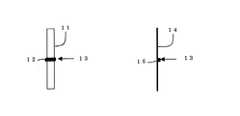
図2は標的の構造であり、縦長のベリリュームの薄膜に、タングステンのワイヤーを張り付けたものと、縦長のベリリュームのワイヤーにビスマスをデポジットした図である。
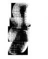
図3は本発明の卓上型放射光治療診断装置を用いて撮像した鶏のX線写真である。鶏の内臓を全て観察することができる。肺胞、食道、血管、羽根などが識別できる。
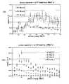
図4は電子エネルギーをX線に変換する標的の厚さを変えたときのX線スペクトルである。(a)はアルミ標的の場合であり、(b)は白金標的の場合である。厚さによりスペクトルのピークが異なる。
図5はX線を水で吸収させた時、水の各深さによる吸収率を示した図である。110KevのX線管と、本発明の卓上型放射光治療診断装置から出るX線を比較したものである。An embodiment of the present invention will be described in detail with reference to FIGS. FIG. 1 is an overall conceptual diagram of a desktop synchrotron radiation diagnostic apparatus according to the present invention. This apparatus includes a microtron high-energy electron generator, an electron circulating device, a device for converting electron energy into X-rays, and an X-ray imaging device. And a shielding device that limits the irradiation field. X-rays are irradiated to the patient from above. In order to change the irradiation direction, the entire apparatus has a mechanism that rotates around the patient as shown in the side view of FIG.
FIG. 2 shows a structure of a target, in which a tungsten wire is attached to a vertically long beryllium thin film and bismuth is deposited on a vertically long beryllium wire.
FIG. 3 is an X-ray photograph of a chicken imaged using the desktop synchrotron radiation treatment diagnostic apparatus of the present invention. All the internal organs of the chicken can be observed. Can identify alveoli, esophagus, blood vessels, feathers, etc.
FIG. 4 is an X-ray spectrum when the thickness of a target for converting electron energy into X-rays is changed. (A) is the case of an aluminum target, and (b) is the case of a platinum target. The peak of the spectrum varies depending on the thickness.
FIG. 5 is a diagram showing the absorption rate at each depth of water when X-rays are absorbed by water. The X-ray emitted from the 110 Kev X-ray tube and the desktop synchrotron radiation diagnostic apparatus of the present invention is compared.
図1において、本卓上型放射光治療診断装置は、高エネルギー電子発生手段としてのマイクロトロン電子加速器1、電子周回装置2、電子エネルギーをX線に変換する標的(X線発生手段)3、ベッドに横たわった患者4、レントゲンフィルム、イメージングプレート、フラットパネル等のX線画像装置5、装置を回転させるための回転駆動機構6、照射視野を限定するための遮蔽コリメータ(遮蔽手段)7から構成されている。ベッドの足及びX線画像装置には、患者とX線画像装置の間隔を変えることの出来る駆動機構8があり、拡大像を撮像できる。 Referring to FIG. 1, the desktop synchrotron radiation diagnostic apparatus includes a
前記マイクロトロン電子加速器1は従来公知の電子加速器であり、ここでは6MeV電子ボルトを発生している。マイクロトロン電子加速器1以外に、ライナックやベータトロン等、電子加速器一般を使用できる。また、エネルギーも6MeV電子ボルトに限定されているわけではなく例えば1メガ電子ボルト〜20メガ電子ボルト程度のエネルギーでもよい。電子周回装置2も公知であり、この装置は電子を特定の軌道に沿って周回させる装置なら何でも良く、所謂、シンクロトロン、電子蓄積リング、ベータトロン、FFAG等を使用できるが、ここでは、完全円形の電子蓄積リングを使用している。前記電子蓄積リングも公知の装置であり、通常加速空洞を内蔵している。しかし通常加速空洞を内蔵していることは必須ではない。また、ここでは完全円形の電子蓄積リングを使用しているが、完全円形である必要はない。 The
電子軌道内に標的を設置することによりX線を発生するX線発生手段は、ターゲット(標的)の大きさ及び材質を適切に選択してX線の特性を変えることにより、診断及び治療を行うことのできるX線を発生できるようにしている。
電子エネルギーをX線に変換するための標的であるが、その断面積が小さければ小さいほど精細なX線画像を撮ることができる。標的の断面サイズは、100ミクロン以下であることが望ましい。100ミクロン以下の標的を電子軌道中に投入するには幾つかの困難が有る。標的を保持する方法であるが、例えば10ミクロン径のタングステンワイヤーを使用した場合、ワイヤーの径方向には高い解像度が出るが、長手方向には数mmである電子ビームの大きさにより解像度が決まる。そこで、軽元素で出来た縦長の支持材に、ボール状あるいは柱状の標的を固定する事である。
図2は標的の構造を詳細に説明した図である。50ミクロン厚、幅1mmのベリリューム箔11に10ミクロン幅のタングステン棒12を、その長さ方向が電子の進行方向13になるように接着した図である。長さは、50ミクロンから1mmのものである。
標的をさらに小さくする方法は、ベリリュームのワイヤー14に鉛、ビスマス、等の重元素15をデポジットする方法である。X-ray generation means for generating X-rays by setting a target in an electron orbit performs diagnosis and treatment by appropriately selecting the size and material of the target (target) and changing the X-ray characteristics. X-rays that can be generated are generated.
Although it is a target for converting electron energy into X-rays, the smaller the cross-sectional area, the finer X-ray images can be taken. The cross-sectional size of the target is desirably 100 microns or less. There are several difficulties in placing a target of 100 microns or less into an electron orbit. This is a method of holding the target. For example, when a tungsten wire with a diameter of 10 microns is used, a high resolution is obtained in the radial direction of the wire, but the resolution is determined by the size of the electron beam which is several mm in the longitudinal direction. . Therefore, a ball-shaped or columnar target is fixed to a vertically long support made of a light element.
FIG. 2 is a diagram illustrating the structure of the target in detail. It is the figure which bonded the tungsten rod 12 of 10 micron width to the beryllium foil 11 of 50 micron thickness and 1 mm width so that the length direction may become the advancing direction 13 of an electron. The length is from 50 microns to 1 mm.
A method for further reducing the target is to deposit a
前記標的は電子軌道内に適宜手段で設置することができるが、本例では、コの字型の開いた先端にベリリュームワイヤを張り、その中心に標的を固定し、直線導入器で電子軌道中心に挿入する。幾つかを用意して、回転機構を用いて交換するのも良い。
また、前記卓上型放射光治療診断装置は装置全体を回転するための回転機構を具備することにより、治療と診断の両方を可能にしたものである。回転機構は、図1側面図に示すように患者を中心に回転する機構となっており、現在公知の種々の回転機構を採用することができる。The target can be installed in the electron trajectory by appropriate means. In this example, a beryllium wire is attached to the open end of the U-shape, the target is fixed at the center, and the center of the electron trajectory is detected by a linear introducer. Insert into. Some may be prepared and exchanged using a rotating mechanism.
In addition, the desktop synchrotron radiation diagnostic apparatus is provided with a rotation mechanism for rotating the entire apparatus, thereby enabling both treatment and diagnosis. The rotation mechanism is a mechanism that rotates around the patient as shown in the side view of FIG. 1, and various known rotation mechanisms can be employed.
高エネルギー電子を用いて、精細な医療用診断を行うには、まず、電子エネルギーを数MeVから6MeV程度に設定する事である。電子エネルギーが6MeV程度の時、X線の広がりは、縦横160mrad程度となり、3m離れた位置で48cm程度の被写体を診断できるので、医療装置として成り立つ。電子エネルギーが8MeVを越えると中性子を発生するために危険が伴う。 In order to perform a fine medical diagnosis using high-energy electrons, first, the electron energy is set to several MeV to about 6 MeV. When the electron energy is about 6 MeV, the spread of X-rays is about 160 mrad in the vertical and horizontal directions, and an object of about 48 cm can be diagnosed at a position 3 m away, so that the medical device is realized. When the electron energy exceeds 8 MeV, there is a danger because neutrons are generated.
6MeV電子蓄積リングの電子軌道に上記のようにして製作した標的を挿入してX線を発生して撮像した鶏のX線イメージが図3である。フィルムは通常の医療用X線フィルムである。発生するX線は高エネルギーX線であるために透過力が強く、骨なども透過像であり、そのエッジのみが強調される。視野が広く、標的から2mの場所で15cmの視野がある。標的が小さいために解像度が高く、鶏の内蔵が観察できる。食道や腸、肛門、肺臓、肝臓などの形が見える。羽根が見えるのも驚異的である。本X線写真は従来のX線写真と異なり、吸収像ではなく、造影剤無しで撮ることができる。解像度が高く、肺胞を一つ一つ見ることができる。しかも高エネルギーX線は透過力が強いために、従来のレントゲン写真より被爆量は1/15以下であることが明らかになった。 FIG. 3 shows an X-ray image of a chicken imaged by generating an X-ray by inserting the target manufactured as described above into the electron orbit of the 6 MeV electron storage ring. The film is a normal medical X-ray film. Since the generated X-rays are high-energy X-rays, the transmission power is strong, and bones and the like are also transmitted images, and only the edges are emphasized. The field of view is wide and there is a field of 15 cm at a location 2 m from the target. Because the target is small, the resolution is high and the chicken can be observed. You can see the shape of the esophagus, intestine, anus, lungs and liver. It is also amazing to see the feathers. Unlike conventional X-ray photographs, this X-ray photograph is not an absorption image but can be taken without a contrast agent. The resolution is high and you can see the alveoli one by one. Moreover, since high-energy X-rays have a strong penetrating power, it has been clarified that the exposure amount is 1/15 or less from conventional X-ray photographs.
X線撮像は、約0.1秒で行うことができ、数mGyの照射線量で1枚の写真が撮れる。癌治療に必要な線量は、数Gyから数10Gyであり、従って数10秒から数分で行うことができる。コリメータは照射野を限定するための装置である。即ち、本発明の卓上型放射光治療診断装置から発生するX線は、極めて指向性が高くかつ大強度であるために、診断して病巣の位置を特定し、その場で、病巣以外の部分を遮蔽して、診断しながらピンポイントで治療が出来る装置である。従って、不必要な放射線被爆を避けて、効果的な治療のできる装置である。 X-ray imaging can be performed in about 0.1 seconds, and a single photograph can be taken with an irradiation dose of several mGy. The dose required for cancer treatment is several Gy to several tens Gy, and can be performed in several tens of seconds to several minutes. The collimator is a device for limiting the irradiation field. That is, since the X-ray generated from the desktop synchrotron radiation diagnostic apparatus of the present invention is extremely directional and high intensity, it is diagnosed and the position of the lesion is specified, and the part other than the lesion on the spot It is a device that can be pinpointed while diagnosing and shielding. Therefore, it is an apparatus capable of effective treatment while avoiding unnecessary radiation exposure.
照射に当たっては、癌の種類や位置及び深さによりX線の線質を変えることが出来る。本発明の特徴は、この線質を変更する方法である。利用しているX線は、制動放射により発生している。理論によれば、制動放射の強度は、原子番号が大きいほど大きい。制動放射のスペクトルは標的の材質にはあまり依存しないとされる。しかしながら、発生したX線は、標的内で吸収散乱を受けるために、実際には、標的の材質と電子進行方向の厚さにより異なる。現在、X線スペクトルは、シミュレーションにより、正確に計算ができ、かつ、X線が人体内のどの程度の深さで吸収されるかも計算が出来る。従って、癌の部位により、主にはその深さにより、X線の線質を変えることが本発明の一つであり、かつ、適切な標的の材質と厚さを変えることにより線質を変える手段を有することが本発明の特長である。 In irradiation, the quality of X-rays can be changed depending on the type, position and depth of cancer. A feature of the present invention is a method for changing the line quality. The X-rays used are generated by bremsstrahlung. According to theory, the intensity of bremsstrahlung is higher as the atomic number is higher. The spectrum of bremsstrahlung is considered to be less dependent on the target material. However, since the generated X-rays are absorbed and scattered in the target, the X-rays actually differ depending on the material of the target and the thickness in the electron traveling direction. At present, the X-ray spectrum can be accurately calculated by simulation, and the depth at which the X-ray is absorbed in the human body can also be calculated. Therefore, it is one of the present inventions to change the quality of X-rays depending on the cancer site, mainly depending on the depth thereof, and the quality of the radiation can be changed by changing the material and thickness of an appropriate target. Having the means is a feature of the present invention.
図4は、異なる標的を用いた場合の、スペクトルの違いである。図4(a)は、厚さの異なるAlを標的とした場合であり、図4(b)は、厚さの異なる白金をターゲットした場合である。Alの場合50ミクロンの標的は10KeV近辺にピークを作り、10ミクロンは4から5KeVにピークをつくる。これに対して白金の50ミクロンは60KeVにピークを作り、10ミクロンは12KeVにピークを作る。100ミクロンではピークは100KeV近くになる。この様にして、標的の厚さを変えて治療及び診断を最適化するのが本発明の重要な手段である。 FIG. 4 shows the difference in spectrum when different targets are used. FIG. 4A shows a case where Al having a different thickness is targeted, and FIG. 4B shows a case where platinum having a different thickness is targeted. In the case of Al, a 50-micron target peaks near 10 KeV, and 10-micron peaks from 4 to 5 KeV. In contrast, 50 microns of platinum has a peak at 60 KeV and 10 microns has a peak at 12 KeV. At 100 microns, the peak is close to 100 KeV. In this way, changing the thickness of the target to optimize treatment and diagnosis is an important means of the present invention.
低エネルギーのX線は人体の表面で吸収され、高エネルギーのX線は内部に浸透する。その様子を図5に示す。図5(a)は110KeVのX線管から発生するX線を水に吸収させたときに各深さでのX線吸収率を示している。図5(b)は、6MeV電子、1mm厚鉛標的から発生するX線を水に吸収させた時、各深さでのX線吸収率を示している。図5はX線診断における被爆量を表していて、X線写真を1枚撮るのに必要な被爆量が、本発明の卓上型放射光治療診断装置では、通常のレントゲン写真に比べて1/15であることをも示している。重金属でできた厚い標的を用いることにより、深部の癌を治療するのに適していることも示している。 Low energy X-rays are absorbed by the surface of the human body, and high energy X-rays penetrate inside. This is shown in FIG. FIG. 5A shows the X-ray absorption rate at each depth when X-rays generated from a 110 KeV X-ray tube are absorbed by water. FIG. 5B shows the X-ray absorption rate at each depth when X-rays generated from 6 MeV electrons and a 1 mm thick lead target are absorbed in water. FIG. 5 shows the amount of exposure in X-ray diagnosis, and the amount of exposure necessary for taking one X-ray photograph is 1/0 compared to that in a normal X-ray photograph in the desktop synchrotron radiation treatment diagnostic apparatus of the present invention. 15 is also shown. It has also been shown to be suitable for treating deep cancer by using thick targets made of heavy metals.
本発明の卓上型放射光治療診断装置の利用形態について、以上、主に医療に関わり記述したが、本発明の装置は非破壊検査に用いることもできる。検査対象により、線質をかえるという本発明は、そのまま非破壊検査にも適用することができる。構造物の非破壊検査には、エネルギーの高いX線を用い、柔らかい試料には、エネルギーの低いX線を用いる。このように本発明の卓上型放射光治療診断装置は様々な分野に利用できるので、X線の発生方向は、図1の様に上下方向に限る物ではない。被写体も人間とは限らず、動物、細菌あるいは生物試料、あるいは無機物や構造物を対照とすることができる。従って、非破棄検査や、滅菌や殺菌にも使うことができる。 The use form of the desktop synchrotron radiation treatment diagnostic apparatus of the present invention has been described mainly relating to medical treatment, but the apparatus of the present invention can also be used for nondestructive inspection. The present invention of changing the line quality depending on the inspection object can be applied to the nondestructive inspection as it is. X-rays with high energy are used for nondestructive inspection of structures, and X-rays with low energy are used for soft samples. As described above, the desktop synchrotron radiation treatment diagnostic apparatus of the present invention can be used in various fields, and the X-ray generation direction is not limited to the vertical direction as shown in FIG. The subject is not limited to a human being, but can be an animal, bacteria, biological sample, or inorganic substance or structure. Therefore, it can be used for non-discard inspection, sterilization and sterilization.
また本発明はその精神また主要な特徴から逸脱することなく、他の色々な形で実施することができる。そのため前述の実施例は単なる例示に過ぎず、限定的に解釈してはならない。更に特許請求の範囲の均等範囲に属する変形や変更は全て本発明の範囲内のものである。 In addition, the present invention can be implemented in various other forms without departing from the spirit and main features thereof. For this reason, the above-described embodiments are merely examples, and should not be interpreted in a limited manner. Further, all modifications and changes belonging to the equivalent scope of the claims are within the scope of the present invention.
本発明の卓上型放射光治療診断装置の利用形態について、主に医療に関わり記述したが、本発明の装置は非破壊検査に用いることもできる。検査対象により、線質をかえるという本発明は、そのまま非破壊検査にも適用することができる。構造物の非破壊検査には、エネルギーの高いX線を用い、柔らかい試料には、エネルギーの低いX線を用いる。このように本発明の卓上型放射光治療診断装置は様々な分野に利用できるので、X線の発生方向は、図1の様に上下方向に限る物ではない。被写体も人間とは限らず、動物、細菌あるいは生物試料、あるいは無機物や構造物を対照とすることができる。従って、非破棄検査や、滅菌や殺菌にも使うことができる。 Although the use form of the desktop radiation therapy diagnostic apparatus of the present invention has been described mainly related to medical care, the apparatus of the present invention can also be used for nondestructive inspection. The present invention of changing the line quality depending on the inspection object can be applied to the nondestructive inspection as it is. X-rays with high energy are used for nondestructive inspection of structures, and X-rays with low energy are used for soft samples. As described above, the desktop synchrotron radiation diagnostic apparatus according to the present invention can be used in various fields, and the X-ray generation direction is not limited to the vertical direction as shown in FIG. The subject is not limited to a human being, but can be an animal, bacteria, biological sample, or inorganic substance or structure. Therefore, it can be used for non-discard inspection, sterilization and sterilization.
1 マイクロトロン電子加速器
2 電子周回装置
3 標的(X線発生手段)
4 患者
5 X線画像装置
6 回転機構
7 遮蔽コリメータ
11 ベリリューム泊
12 タングステン棒
13 電子の進行方向
14 ワイヤー
15 微少重元素
1
4
Claims (7)
Translated fromJapaneseThe table-type synchrotron radiation treatment diagnostic apparatus according to any one of claims 1 to 6, wherein a target having a different thickness and material is prepared for the target, and the quality of the generated X-ray is changed by replacing the target. A method of using a desktop synchrotron radiation diagnostic apparatus characterized by optimizing treatment and diagnosis.
Priority Applications (1)
| Application Number | Priority Date | Filing Date | Title |
|---|---|---|---|
| JP2004052994AJP2005237730A (en) | 2004-02-27 | 2004-02-27 | Desktop type radiation therapy/diagnosis apparatus and method of using the same |
Applications Claiming Priority (1)
| Application Number | Priority Date | Filing Date | Title |
|---|---|---|---|
| JP2004052994AJP2005237730A (en) | 2004-02-27 | 2004-02-27 | Desktop type radiation therapy/diagnosis apparatus and method of using the same |
Publications (1)
| Publication Number | Publication Date |
|---|---|
| JP2005237730Atrue JP2005237730A (en) | 2005-09-08 |
Family
ID=35020075
Family Applications (1)
| Application Number | Title | Priority Date | Filing Date |
|---|---|---|---|
| JP2004052994APendingJP2005237730A (en) | 2004-02-27 | 2004-02-27 | Desktop type radiation therapy/diagnosis apparatus and method of using the same |
Country Status (1)
| Country | Link |
|---|---|
| JP (1) | JP2005237730A (en) |
Cited By (17)
| Publication number | Priority date | Publication date | Assignee | Title |
|---|---|---|---|---|
| JP2008082779A (en)* | 2006-09-26 | 2008-04-10 | Japan Atomic Energy Agency | Complex type waste object confirming system |
| JP2010022732A (en)* | 2008-07-24 | 2010-02-04 | Fujifilm Corp | Radiation image photographing system |
| JP2010506689A (en)* | 2006-10-16 | 2010-03-04 | オラヤ セラピューティクス,インコーポレーテッド | Eye radiosurgery |
| JP2012524374A (en)* | 2009-04-16 | 2012-10-11 | エリック・エイチ・シルバー | Monochromatic X-ray method and apparatus |
| US8494116B2 (en) | 2007-12-23 | 2013-07-23 | Oraya Therapeutics, Inc. | Methods and devices for orthovoltage ocular radiotherapy and treatment planning |
| US8503609B2 (en) | 2007-12-23 | 2013-08-06 | Oraya Therapeutics, Inc. | Methods and devices for detecting, controlling, and predicting radiation delivery |
| US8506558B2 (en) | 2008-01-11 | 2013-08-13 | Oraya Therapeutics, Inc. | System and method for performing an ocular irradiation procedure |
| US8630388B2 (en) | 2007-06-04 | 2014-01-14 | Oraya Therapeutics, Inc. | Method and device for ocular alignment and coupling of ocular structures |
| US8787524B2 (en) | 2006-12-13 | 2014-07-22 | Oraya Therapeutics, Inc. | Orthovoltage radiotherapy |
| CN105307376A (en)* | 2015-09-05 | 2016-02-03 | 刘洋 | Medical electron linear accelerator |
| CN108175958A (en)* | 2018-03-16 | 2018-06-19 | 西安大医数码科技有限公司 | Focus head, collimator and gamma knife |
| US10398909B2 (en) | 2017-05-19 | 2019-09-03 | Imagine Scientific, Inc. | Monochromatic x-ray systems and methods |
| WO2019174461A1 (en)* | 2018-03-16 | 2019-09-19 | 西安大医集团有限公司 | Focusing head, collimator and gamma knife |
| US10818467B2 (en) | 2018-02-09 | 2020-10-27 | Imagine Scientific, Inc. | Monochromatic x-ray imaging systems and methods |
| US11158435B2 (en) | 2018-09-14 | 2021-10-26 | Imagine Scientific, Inc. | Monochromatic x-ray component systems and methods |
| US11213265B2 (en) | 2018-02-09 | 2022-01-04 | Imagine Scientific, Inc. | Monochromatic x-ray imaging systems and methods |
| US12253480B2 (en) | 2014-06-24 | 2025-03-18 | Imagine Scientific, Inc. | Methods and apparatus for determining information regarding chemical composition using x-ray radiation |
- 2004
- 2004-02-27JPJP2004052994Apatent/JP2005237730A/enactivePending
Cited By (40)
| Publication number | Priority date | Publication date | Assignee | Title |
|---|---|---|---|---|
| JP2008082779A (en)* | 2006-09-26 | 2008-04-10 | Japan Atomic Energy Agency | Complex type waste object confirming system |
| JP2010506689A (en)* | 2006-10-16 | 2010-03-04 | オラヤ セラピューティクス,インコーポレーテッド | Eye radiosurgery |
| US8995618B2 (en) | 2006-10-16 | 2015-03-31 | Oraya Therapeutics, Inc. | Portable orthovoltage radiotherapy |
| US8855267B2 (en) | 2006-10-16 | 2014-10-07 | Oraya Therapeutics, Inc. | Orthovoltage radiosurgery |
| US8837675B2 (en) | 2006-10-16 | 2014-09-16 | Oraya Therapeutics, Inc. | Ocular radiosurgery |
| US8611497B2 (en) | 2006-10-16 | 2013-12-17 | Oraya Therapeutics, Inc. | Portable orthovoltage radiotherapy |
| US8761336B2 (en) | 2006-10-16 | 2014-06-24 | Oraya Therapeutics, Inc. | Orthovoltage radiotherapy |
| US8787524B2 (en) | 2006-12-13 | 2014-07-22 | Oraya Therapeutics, Inc. | Orthovoltage radiotherapy |
| US9272161B2 (en) | 2006-12-13 | 2016-03-01 | Oraya Therapeutics, Inc. | Orthovoltage radiotherapy |
| US8923479B2 (en) | 2007-06-04 | 2014-12-30 | Oraya Therapeutics, Inc. | Method and device for ocular alignment and coupling of ocular structures |
| US8630388B2 (en) | 2007-06-04 | 2014-01-14 | Oraya Therapeutics, Inc. | Method and device for ocular alignment and coupling of ocular structures |
| US9025727B2 (en) | 2007-12-23 | 2015-05-05 | Oraya Therapeutics, Inc. | Methods and devices for orthovoltage ocular radiotherapy and treatment planning |
| US8848869B2 (en) | 2007-12-23 | 2014-09-30 | Oraya Therapeutics, Inc. | Methods and devices for detecting, controlling, and predicting radiation delivery |
| US8503609B2 (en) | 2007-12-23 | 2013-08-06 | Oraya Therapeutics, Inc. | Methods and devices for detecting, controlling, and predicting radiation delivery |
| US8494116B2 (en) | 2007-12-23 | 2013-07-23 | Oraya Therapeutics, Inc. | Methods and devices for orthovoltage ocular radiotherapy and treatment planning |
| US8512236B2 (en) | 2008-01-11 | 2013-08-20 | Oraya Therapeutics, Inc. | System and method for positioning and stabilizing an eye |
| US8506558B2 (en) | 2008-01-11 | 2013-08-13 | Oraya Therapeutics, Inc. | System and method for performing an ocular irradiation procedure |
| US8920406B2 (en) | 2008-01-11 | 2014-12-30 | Oraya Therapeutics, Inc. | Device and assembly for positioning and stabilizing an eye |
| JP2010022732A (en)* | 2008-07-24 | 2010-02-04 | Fujifilm Corp | Radiation image photographing system |
| JP2016000313A (en)* | 2009-04-16 | 2016-01-07 | エリック・エイチ・シルバーSILVER, Eric, H. | Monochrome x-ray method and device |
| JP2012524374A (en)* | 2009-04-16 | 2012-10-11 | エリック・エイチ・シルバー | Monochromatic X-ray method and apparatus |
| US11903754B2 (en) | 2009-04-16 | 2024-02-20 | Imagine Scientific, Inc. | Monochromatic X-ray methods and apparatus |
| US9326744B2 (en) | 2009-04-16 | 2016-05-03 | Eric H. Silver | Monochromatic X-ray methods and apparatus |
| US10299743B2 (en) | 2009-04-16 | 2019-05-28 | Imagine Scientific, Inc. | Monochromatic X-ray methods and apparatus |
| US12253480B2 (en) | 2014-06-24 | 2025-03-18 | Imagine Scientific, Inc. | Methods and apparatus for determining information regarding chemical composition using x-ray radiation |
| CN105307376A (en)* | 2015-09-05 | 2016-02-03 | 刘洋 | Medical electron linear accelerator |
| US11185714B2 (en) | 2017-05-19 | 2021-11-30 | Imagine Scientific, Inc. | Monochromatic x-ray imaging systems and methods |
| US10398909B2 (en) | 2017-05-19 | 2019-09-03 | Imagine Scientific, Inc. | Monochromatic x-ray systems and methods |
| US10532223B2 (en) | 2017-05-19 | 2020-01-14 | Imagine Scientific, Inc. | Monochromatic X-ray imaging systems and methods |
| US11833369B2 (en) | 2017-05-19 | 2023-12-05 | Imagine Scientific, Inc. | Monochromatic x-ray imaging systems and methods |
| US10806946B2 (en) | 2017-05-19 | 2020-10-20 | Imagine Scientific, Inc. | Monochromatic X-ray systems and methods |
| US10398910B2 (en) | 2017-05-19 | 2019-09-03 | Imagine Scientific, Inc. | Monochromatic X-ray imaging systems and methods |
| US10857383B2 (en) | 2017-05-19 | 2020-12-08 | Imagine Scientific, Inc. | Monochromatic x-ray systems and methods |
| US11213265B2 (en) | 2018-02-09 | 2022-01-04 | Imagine Scientific, Inc. | Monochromatic x-ray imaging systems and methods |
| US10818467B2 (en) | 2018-02-09 | 2020-10-27 | Imagine Scientific, Inc. | Monochromatic x-ray imaging systems and methods |
| US11744536B2 (en) | 2018-02-09 | 2023-09-05 | Imagine Scientific, Inc. | Monochromatic x-ray imaging systems and methods |
| CN108175958B (en)* | 2018-03-16 | 2020-03-17 | 西安大医集团有限公司 | Focusing head, collimator and gamma knife |
| WO2019174461A1 (en)* | 2018-03-16 | 2019-09-19 | 西安大医集团有限公司 | Focusing head, collimator and gamma knife |
| CN108175958A (en)* | 2018-03-16 | 2018-06-19 | 西安大医数码科技有限公司 | Focus head, collimator and gamma knife |
| US11158435B2 (en) | 2018-09-14 | 2021-10-26 | Imagine Scientific, Inc. | Monochromatic x-ray component systems and methods |
Similar Documents
| Publication | Publication Date | Title |
|---|---|---|
| US11903754B2 (en) | Monochromatic X-ray methods and apparatus | |
| CN101927065B (en) | Compact microbeam radiation therapy systems and methods for cancer treatment and research | |
| JP2005237730A (en) | Desktop type radiation therapy/diagnosis apparatus and method of using the same | |
| US5008907A (en) | Therapy x-ray scanner | |
| CN101559260B (en) | Device for carrying out irradiation and method for monitoring same | |
| US10500420B2 (en) | Small beam area, mid-voltage radiotherapy system with reduced skin dose, reduced scatter around the treatment volume, and improved overall accuracy | |
| US10188878B2 (en) | Small beam area, mid-voltage radiotherapy system with reduced skin dose, reduced scatter around the treatment volume, and improved overall accuracy | |
| JP2010075338A (en) | Mammography and therapy apparatus equipped with x-ray therapy function | |
| JP2005507684A (en) | Antiproton production and delivery for imaging and killing of unwanted cells | |
| WO2017180513A1 (en) | Real-time, parallel x-ray tomosynthesis | |
| US20130294576A1 (en) | Monochromatic x-ray devices and methods of use | |
| US7120224B2 (en) | X-ray imaging apparatus and method for mammography and computed tomography | |
| Thomlinson | Medical applications of synchrotron radiation | |
| CN210057184U (en) | In-situ CT device integrated into fixed particle beam radiotherapy room | |
| JPS63168600A (en) | X-ray source | |
| CN105477793B (en) | A nuclear radiotherapy source container structure | |
| Karl-Scholz et al. | Basic Knowledge Radiology | |
| Davidson et al. | Nanoparticle-assisted scanning focusing X-ray therapy with needle beam X rays | |
| Sasaki et al. | Medical X‐ray Imaging by MIRRORCLE‐6X | |
| HK1167774A (en) | Monochromatic x-ray apparatus | |
| HK1167774B (en) | Monochromatic x-ray apparatus | |
| Adani et al. | Neutron imaging using medical linacs | |
| Thute et al. | Development of an image-guided radiation therapy device for precise irradiation of small animal tumors |
Legal Events
| Date | Code | Title | Description |
|---|---|---|---|
| RD03 | Notification of appointment of power of attorney | Free format text:JAPANESE INTERMEDIATE CODE: A7423 Effective date:20051003 | |
| A621 | Written request for application examination | Free format text:JAPANESE INTERMEDIATE CODE: A621 Effective date:20061020 | |
| A131 | Notification of reasons for refusal | Free format text:JAPANESE INTERMEDIATE CODE: A131 Effective date:20090805 | |
| A02 | Decision of refusal | Free format text:JAPANESE INTERMEDIATE CODE: A02 Effective date:20100113 |