JP2005234498A - Optical fiber tape core protecting member and optical fiber connector ferrule connection method - Google Patents
Optical fiber tape core protecting member and optical fiber connector ferrule connection methodDownload PDFInfo
- Publication number
- JP2005234498A JP2005234498AJP2004046932AJP2004046932AJP2005234498AJP 2005234498 AJP2005234498 AJP 2005234498AJP 2004046932 AJP2004046932 AJP 2004046932AJP 2004046932 AJP2004046932 AJP 2004046932AJP 2005234498 AJP2005234498 AJP 2005234498A
- Authority
- JP
- Japan
- Prior art keywords
- optical fiber
- protection member
- ferrule
- ribbon
- connector
- Prior art date
- Legal status (The legal status is an assumption and is not a legal conclusion. Google has not performed a legal analysis and makes no representation as to the accuracy of the status listed.)
- Granted
Links
Images


Landscapes
- Mechanical Coupling Of Light Guides (AREA)
Abstract
Description
Translated fromJapanese本発明は、主として多心の光ファイバを一括して接続することができる、いわゆるMT光ファイバコネクタに好適なブーツの構造およびこれを用いた光ファイバコネクタフェルールへの接続方法に関する。 The present invention relates to a boot structure suitable for a so-called MT optical fiber connector capable of connecting multi-core optical fibers in a lump and a method for connecting to an optical fiber connector ferrule using the same.
最近の大規模な光加入者系通信網の拡大による光ファイバケーブルの多心化・高密度化にともない,多心コネクタによる接続の一括化が不可欠となっている。
このため現在、光アクセス系のケーブル接続にMT光ファイバコネクタ(以下MTコネクタという)を5個単位で一括接続する,5連一括接続技術が実用化されているが,さらに一層小型化・多心化した高密度実装技術が求められている。With the recent increase in the number of optical fiber cables and the increase in density due to the expansion of a large-scale optical subscriber network, it is indispensable to integrate connections using multi-fiber connectors.
For this reason, a 5-unit batch connection technology is currently put to practical use, in which MT optical fiber connectors (hereinafter referred to as MT connectors) are connected in units of 5 for optical access system cable connections. High-density mounting technology is required.
この要求に対して、従来のMTコネクタの形状および寸法を変更することなく,さらなる高密度実装を実現すべく光ファイバテープ心線を複数枚にわたって積層、装着し、この結果光ファイバ心線がMTコネクタの接触面上で、X−Y方向の二次元に配列されて高密度に実装可能とした多心光コネクタが開発されている。
前記特許文献の第1図に示されているように、MTコネクタの後端面に穿孔された光ファイバテープ心線の挿入孔入口の近傍において、光ファイバテープ心線の過度な屈曲を防止するための光ファイバテープ心線保護部材11(以下ブーツという)が光ファイバテープ心線の外側に装着されている。 As shown in FIG. 1 of the above-mentioned patent document, in order to prevent excessive bending of the optical fiber ribbon in the vicinity of the insertion hole entrance of the optical fiber ribbon drilled in the rear end surface of the MT connector. 1 is attached to the outside of the optical fiber ribbon.
このブーツの装着時期は、光ファイバテープ心線の先端部分が前記光ファイバテープ心線挿入孔に挿入される前に予め前記光ファイバテープ心線の表面に遊嵌状態で装着される。
換言すれば、光ファイバテープ心線がMTコネクタフェルールの挿入孔に挿入される際は、すでにこのブーツが光ファイバテープ心線の先端部分に予め装着されている構成となっている。When the boot is mounted, the front end portion of the optical fiber ribbon is inserted in advance on the surface of the optical fiber ribbon before being inserted into the optical fiber ribbon insertion hole.
In other words, when the optical fiber ribbon is inserted into the insertion hole of the MT connector ferrule, the boot is already attached to the tip portion of the optical fiber ribbon.
しかしながら何らかの理由、例えば光ファイバテープ心線を具備する光ファイバコードに前記コネクタフェルールを装着する際、当該光ファイバコードの先端部分の外部被覆(以下コード外被という)を必要な長さに渡って剥離除去できない場合、まず光ファイバテープ心線の先端部をMTコネクタフェルールに取り付け、その後ブーツを後付することが可能であればきわめて有益で使い勝手がよい。 However, for some reason, for example, when the connector ferrule is attached to an optical fiber cord having an optical fiber ribbon, an outer coating (hereinafter referred to as a cord jacket) of the tip portion of the optical fiber cord is required for a required length. If peeling and removal cannot be performed, it is extremely useful and convenient if the tip of the optical fiber ribbon is first attached to the MT connector ferrule and then the boot can be retrofitted.
この発明が解決しようとする課題は、まさにこの点に鑑みて発明されたものであって、光ファイバテープ心線の先端部がコネクタのフェルールに支持され後に光ファイバテープ心線の外側から装着することができる光ファイバテープ心線保護部材および光ファイバコネクタの接続方法を提供することを目的とする。 The problem to be solved by the present invention has been invented in view of this point. The tip of the optical fiber ribbon is supported by the ferrule of the connector and then attached from the outside of the optical fiber ribbon. An object of the present invention is to provide an optical fiber ribbon protective member and a method for connecting an optical fiber connector.
本発明では、上記の目的を達成するために、第1の課題解決手段は光ファイバコネクタのフェルールの後端面に穿孔された光ファイバテープ心線の挿入孔に予め接続された光ファイバテープ心線に装着される光ファイバテープ心線保護部材であって、この光ファイバテープ心線保護部材は前記光ファイバコネクタのフェルールに接続された少なくとも一枚の光ファイバテープ心線を挿通するためのスリットが前記光ファイバテープ心線保護部材の側縁部に形成されるように構成したものである。 In the present invention, in order to achieve the above object, the first problem-solving means is an optical fiber ribbon pre-connected to an insertion hole of an optical fiber ribbon drilled in the rear end surface of the ferrule of the optical fiber connector. An optical fiber ribbon protection member attached to the optical fiber tape, the optical fiber ribbon protection member having a slit for inserting at least one optical fiber ribbon connected to the ferrule of the optical fiber connector. It is configured to be formed on a side edge portion of the optical fiber ribbon protection member.
第二の課題解決手段は、前記の光ファイバ心線保護部材の内部側壁にその長手方向に沿って一枚の隔離板が片持状態で突設されて成り、この隔離板を挟んで複数枚の光ファイバテープ心線が前記スリットから挿入し、収納するように構成されるものである。 The second problem-solving means is configured such that a single separator is projected in a cantilevered manner along the longitudinal direction of the inner side wall of the optical fiber core protection member, and a plurality of sheets are sandwiched between the separators. The optical fiber ribbon is inserted into the slit and stored.
第三の課題解決手段は、二枚以上の光ファイバテープ心線が収納できるようにうに隔離板が複数枚、片持状態で突設されて成る構成とされる。 The third problem-solving means is configured such that a plurality of separators project in a cantilever state so that two or more optical fiber ribbons can be accommodated.
第四の課題解決手段は、光ファイバ心線保護部材の内部に、その長手方向に沿って一枚の隔離板がこの光ファイバ心線保護部材の対向する両側内部側壁に一体に連結されて成り、かつこの隔離板を挟んで上方側板および下方側板のそれぞれにスリットが形成されるように構成される。 According to a fourth means for solving the problem, an optical fiber core protecting member is integrally connected to the opposite side walls on both sides of the optical fiber core protecting member in the longitudinal direction. And it is comprised so that a slit may be formed in each of an upper side board and a lower side board on both sides of this separator.
第五の課題解決手段は、一枚以上の光ファイバテープ心線先端部の各光ファイバ素線を光ファイバコネクタのフェルールに接続した後、この光ファイバテープ心線の側面からスリットを備えた光ファイバテープ心線保護部材を装着し、次いでこの光ファイバテープ心線保護部材を前記フェルールの後端面に穿孔された光ファイバテープ心線挿入孔に摺動させるように構成される。 According to a fifth means for solving the problem, after connecting each of the optical fiber strands of one or more optical fiber ribbon cores to a ferrule of an optical fiber connector, a light having a slit is provided from the side of the optical fiber ribbon. A fiber tape core wire protection member is mounted, and then the optical fiber tape core wire protection member is slid into an optical fiber tape core wire insertion hole formed in the rear end surface of the ferrule.
第一の課題解決手段によれば、光ファイバコネクタのフェルールの後端面に接続されている光ファイバテープ心線にその側面から光ファイバ心線保護部材を追加して装着できる。 According to the first problem solving means, the optical fiber core protecting member can be additionally attached from the side surface to the optical fiber tape core connected to the rear end surface of the ferrule of the optical fiber connector.
第二の課題解決手段によれば、隔離板を介して複数枚の光ファイバテープ心線を積層して収納することが出来る。 According to the second problem solving means, a plurality of optical fiber ribbons can be stacked and stored via the separator.
第三の課題解決手段によれば、より枚数の多い光ファイバテープ心線を積層状態に収容することが出来る。 According to the third problem solving means, a larger number of optical fiber ribbons can be accommodated in a laminated state.
第四の課題解決手段によれば、光ファイバコネクタのフェルールの後端面に接続されている複数枚の光ファイバテープ心線をその表面および裏面から光ファイバ心線保護部材を追加して装着できる。 According to the fourth problem solving means, a plurality of optical fiber ribbons connected to the rear end face of the ferrule of the optical fiber connector can be additionally attached from the front surface and the back surface thereof.
第五の課題解決手段によれば、光ファイバテープ心線の光ファイバ素線群をコネクタフェルールに接続した後に、光ファイバテープ心線の保護部材を後から装着することが出来る。 According to the fifth problem solving means, after connecting the optical fiber strand group of the optical fiber ribbon to the connector ferrule, the protective member for the optical fiber ribbon can be attached later.
光ファイバテープ心線の先端部をコネクタのフェルールに接続した後においても、光ファイバテープ心線保護部材を装着できるという目的が達成できる有利な保護部材を実現した。 Even after the tip of the optical fiber ribbon is connected to the ferrule of the connector, an advantageous protective member that can achieve the object of being able to attach the optical fiber ribbon protective member is realized.
図1〜図3に示すように、光ファイバコード1の先端部の外被が除去され、複数枚、例えば2枚の光ファイバテープ心線2、3が取り出され、さらにこの各光ファイバテープ心線2,3の先端部の被覆層が剥離除去され、それぞれの光ファイバテープ心線の光ファイバ心線群2A、3A、例えば8心、12心あるいは16心が露出される。 As shown in FIGS. 1 to 3, the outer jacket of the tip portion of the optical fiber cord 1 is removed, and a plurality of, for example, two
そして前記光ファイバ心線群2A、3Aは、図3に示されるMTコネクタフェルール4の後端面に穿孔された光ファイバテープ心線の挿入孔5を経て,フェルール4の先端面に達するまで貫通穿孔されている光ファイバ心線ガイド孔4A、4Bに挿入された後、接着剤、その他の固着手段を介してフェルール4に接続される。 The optical
なお、前記光ファイバ心線ガイド孔4A、4Bはフェルール4に接続される光ファイバテープ心線の枚数が2枚の場合は2段に形成されるが接続される光ファイバテープ心線の枚数に応じて3段、4段、5段と積層することができる。 The optical fiber
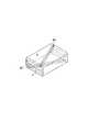
このようにして前記光ファイバ心線群2A、3Aがフェルール4に接続された後、図1に示される光ファイバテープ心線保護部材6(ブーツ)のスリット8に光ファイバテープ心線2、3が挿入される。 After the optical
この光ファイバテープ心線保護部材6は天然ゴムあるいはエチレン・ブタジエンゴム等の熱可塑性エラストマーで構成され、全体として略直方体形状を呈しその横断面はフェルール4の後部端面に穿孔された光ファイバテープ心線挿入孔5を気密に閉塞するために十分な大きさを備えている。 This optical fiber tape
さらに前記光ファイバテープ心線保護部材6の一方の側壁の内部においてその長手方向に沿って一枚の隔離板7が片持状態で突設支持されおり、他方の側壁にはその長手方向に沿ってスリット8が全長にわたって切欠き形成されている。なお、この隔離板7は複数枚を平行な状態にして片持状態で突設支持することもできる。 Further, one
この隔離板7は、各光ファイバテープ心線の光ファイバ素線が前記光ファイバ心線ガイド孔4A、4Bに対して容易に挿入し得るように各光ファイバテープ心線を一定の間隔に保持するスペーサとして機能する。 The
フェルール4に接続された光ファイバテープ心線2,3に前記光ファイバテープ心線保護部材6を装着する場合は、各光ファイバテープ心線が前記隔離板7を挟んでその両側に配置されるように前記スリット8から挿入される。次いで、この前記光ファイバテープ心線保護部材6を光ファイバテープ心線挿入孔5に向けて摺動させ、この挿入孔5を閉塞すると共にフェルール4に対して光ファイバテープ心線を固定し保護する。 When the optical fiber
なお、前記の光ファイバテープ心線保護部材6は、それ自体の弾性によってフェルール4の付け根の部分において光ファイバテープ心線2,3に外部応力が作用した際、光ファイバテープ心線の過度の屈曲を防止するように構成される。 The optical fiber tape
図4はこの発明の第2の実施例を示すものであって、光ファイバ心線保護部材6の内部には、その長手方向に沿って一枚の隔離板7がこの光ファイバ心線保護部材の対向する両側内部側壁に一体に連結されて成り、かつこの隔離板7を挟んで上下に位置する上方側板および下方側板にそれぞれスリット8Aおよび8Bが切欠き形成されている。 FIG. 4 shows a second embodiment of the present invention. In the optical fiber
この保護部材6を装着する場合は、一方のスリット8Aから少なくとも一枚の光ファイバテープ心線が挿入され、次いで他方のスリット8Bから少なくとも一枚の光ファイバテープ心線が挿入される。 When this
図5はこの発明の第3の実施例を示すものであって、第2の実施例と比較して隔離板7を挟んで位置する上方側板および下方側板に切欠き成形されたスリット8Aおよび8Bがそれぞれの側板の略対角線上に位置する。このようにすることによって両端におけるスリットの開口部の位置を異ならすことが出来、光ファイバテープ心線から心線保護部材6が離脱し易くなることを防止できる。また側板の開口部分を広げることが出来るので装着しやすくなる。 FIG. 5 shows a third embodiment of the present invention. Compared with the second embodiment,
従来の接続方法、すなわち光ファイバテープ心線保護部材6を予め一枚以上の光ファイバテープ心線の途中に挿通しておき、光ファイバ心線がフェルール4に接続された後、この心線保護部材6をフェルール後端部の光ファイバテープ心線挿入孔5に向けて摺動させ、この挿入孔5に固定することもできる。
さらにまた、既設のフェルールに新たな心線保護部材6を装着することも出来る。A conventional connecting method, that is, an optical fiber
Furthermore, a new core
1光ファイバコード
2光ファイバテープ心線
3光ファイバテープ心線
4光ファイバコネクタフェルール
5光ファイバテープ心線挿入孔
6光ファイバテープ心線保護部材
7隔離板
8A、8Bスリット1
Claims (5)
Translated fromJapaneseAfter connecting each optical fiber strand at the tip of one or more optical fiber ribbons to a ferrule of an optical fiber connector, attach an optical fiber ribbon protection member with a slit from the side of this optical fiber ribbon Then, the optical fiber connector core wire protecting member is slid into the optical fiber tape core wire insertion hole formed in the rear end face of the ferrule.
Priority Applications (1)
| Application Number | Priority Date | Filing Date | Title |
|---|---|---|---|
| JP2004046932AJP4395389B2 (en) | 2004-02-23 | 2004-02-23 | Optical fiber tape core protecting member and optical fiber connector ferrule connection method |
Applications Claiming Priority (1)
| Application Number | Priority Date | Filing Date | Title |
|---|---|---|---|
| JP2004046932AJP4395389B2 (en) | 2004-02-23 | 2004-02-23 | Optical fiber tape core protecting member and optical fiber connector ferrule connection method |
Publications (2)
| Publication Number | Publication Date |
|---|---|
| JP2005234498Atrue JP2005234498A (en) | 2005-09-02 |
| JP4395389B2 JP4395389B2 (en) | 2010-01-06 |
Family
ID=35017475
Family Applications (1)
| Application Number | Title | Priority Date | Filing Date |
|---|---|---|---|
| JP2004046932AExpired - Fee RelatedJP4395389B2 (en) | 2004-02-23 | 2004-02-23 | Optical fiber tape core protecting member and optical fiber connector ferrule connection method |
Country Status (1)
| Country | Link |
|---|---|
| JP (1) | JP4395389B2 (en) |
Cited By (6)
| Publication number | Priority date | Publication date | Assignee | Title |
|---|---|---|---|---|
| JP2011033728A (en)* | 2009-07-30 | 2011-02-17 | Fujikura Ltd | Boot, optical connector, and method of manufacturing optical connector |
| WO2012157276A1 (en)* | 2011-05-19 | 2012-11-22 | コニカミノルタアドバンストレイヤー株式会社 | Optical connector plug, optical probe, and optical system |
| JP2017016013A (en)* | 2015-07-03 | 2017-01-19 | 住友電気工業株式会社 | Connector boots, connectors and optical fiber cores with connectors |
| JP2017021184A (en)* | 2015-07-10 | 2017-01-26 | 住友電気工業株式会社 | Coated optical fiber with connector |
| EP3176617A1 (en)* | 2015-12-04 | 2017-06-07 | Sanwa Denki Kogyo Co., Ltd. | Boot for optical connector ferrule |
| US11630267B2 (en)* | 2018-08-31 | 2023-04-18 | Commscope Technologies Llc | Ferrule boot for optical connectors |
- 2004
- 2004-02-23JPJP2004046932Apatent/JP4395389B2/ennot_activeExpired - Fee Related
Cited By (10)
| Publication number | Priority date | Publication date | Assignee | Title |
|---|---|---|---|---|
| JP2011033728A (en)* | 2009-07-30 | 2011-02-17 | Fujikura Ltd | Boot, optical connector, and method of manufacturing optical connector |
| WO2012157276A1 (en)* | 2011-05-19 | 2012-11-22 | コニカミノルタアドバンストレイヤー株式会社 | Optical connector plug, optical probe, and optical system |
| US9709752B2 (en) | 2011-05-19 | 2017-07-18 | Konica Minolta, Inc. | Optical connector plug, optical probe, and optical system |
| JP2017016013A (en)* | 2015-07-03 | 2017-01-19 | 住友電気工業株式会社 | Connector boots, connectors and optical fiber cores with connectors |
| JP2017021184A (en)* | 2015-07-10 | 2017-01-26 | 住友電気工業株式会社 | Coated optical fiber with connector |
| EP3176617A1 (en)* | 2015-12-04 | 2017-06-07 | Sanwa Denki Kogyo Co., Ltd. | Boot for optical connector ferrule |
| CN106873084A (en)* | 2015-12-04 | 2017-06-20 | 三和电气工业株式会社 | Optical connector lock pin protective cover |
| US9891391B2 (en) | 2015-12-04 | 2018-02-13 | Sanwa Denki Kogyo Co. Ltd. | Boot for optical connector ferrule |
| CN106873084B (en)* | 2015-12-04 | 2020-06-26 | 三和电气工业株式会社 | Protective cover for optical connector ferrule |
| US11630267B2 (en)* | 2018-08-31 | 2023-04-18 | Commscope Technologies Llc | Ferrule boot for optical connectors |
Also Published As
| Publication number | Publication date |
|---|---|
| JP4395389B2 (en) | 2010-01-06 |
Similar Documents
| Publication | Publication Date | Title |
|---|---|---|
| US11703652B2 (en) | Fiber optic cable assembly with integrated shuffle and fabrication method | |
| US11079555B2 (en) | Fiber management enclosure for a fiber optic connector assembly and method of use | |
| TW200921171A (en) | Modular optical fiber cassettes and fiber management methods | |
| CN101128764A (en) | Distributed fiber optic cable having at least one access location and method of making same | |
| US10948678B2 (en) | Bi-directional data center architectures including a jacketless trunk cable and methods of forming the same | |
| KR20220160702A (en) | Fiber Optic Ferrules and Fiber Connectors | |
| JP4395389B2 (en) | Optical fiber tape core protecting member and optical fiber connector ferrule connection method | |
| US20120301084A1 (en) | Cable assemblies having labels and methods for making the same | |
| JP5615854B2 (en) | Optical fiber tape and optical fiber cable | |
| JP2008224998A (en) | Optical cable connection closure and optical wiring system | |
| KR100890688B1 (en) | Fiber optic terminal unit | |
| CN107272120A (en) | Optical distribution component | |
| JP3129788B2 (en) | Optical withdrawal connection box and withdrawal method | |
| JP2017207594A (en) | Optical cable, and insertion/removal method | |
| JP2023082955A (en) | fiber optic cable | |
| JP4237079B2 (en) | Optical fiber cable connection method | |
| JP5289718B2 (en) | Optical wiring system | |
| JP2002267902A (en) | Terminal structure of optical cable with connector | |
| JP4731461B2 (en) | Branch structure of multi-core optical fiber with optical connector | |
| JPH1048491A (en) | Terminal structure of optical cable with connector | |
| US20230266522A1 (en) | Compact cable assembly | |
| JP4252588B2 (en) | Fiber optic cable | |
| JP3234296B2 (en) | Multi-core optical connector | |
| CN111239914B (en) | A Metro Backbone Transport Network Optical Cross-Connect Device | |
| JPH1144833A (en) | Optical fiber |
Legal Events
| Date | Code | Title | Description |
|---|---|---|---|
| A621 | Written request for application examination | Free format text:JAPANESE INTERMEDIATE CODE: A621 Effective date:20061128 | |
| A977 | Report on retrieval | Free format text:JAPANESE INTERMEDIATE CODE: A971007 Effective date:20090106 | |
| A131 | Notification of reasons for refusal | Free format text:JAPANESE INTERMEDIATE CODE: A131 Effective date:20090113 | |
| A521 | Written amendment | Free format text:JAPANESE INTERMEDIATE CODE: A523 Effective date:20090223 | |
| TRDD | Decision of grant or rejection written | ||
| A01 | Written decision to grant a patent or to grant a registration (utility model) | Free format text:JAPANESE INTERMEDIATE CODE: A01 Effective date:20090929 | |
| A01 | Written decision to grant a patent or to grant a registration (utility model) | Free format text:JAPANESE INTERMEDIATE CODE: A01 | |
| A61 | First payment of annual fees (during grant procedure) | Free format text:JAPANESE INTERMEDIATE CODE: A61 Effective date:20091019 | |
| FPAY | Renewal fee payment (prs date is renewal date of database) | Free format text:PAYMENT UNTIL: 20121023 Year of fee payment:3 | |
| FPAY | Renewal fee payment (prs date is renewal date of database) | Free format text:PAYMENT UNTIL: 20121023 Year of fee payment:3 | |
| FPAY | Renewal fee payment (prs date is renewal date of database) | Free format text:PAYMENT UNTIL: 20131023 Year of fee payment:4 | |
| R250 | Receipt of annual fees | Free format text:JAPANESE INTERMEDIATE CODE: R250 | |
| LAPS | Cancellation because of no payment of annual fees |