JP2005231450A - Obstacle detection device for vehicle - Google Patents
Obstacle detection device for vehicleDownload PDFInfo
- Publication number
- JP2005231450A JP2005231450AJP2004041360AJP2004041360AJP2005231450AJP 2005231450 AJP2005231450 AJP 2005231450AJP 2004041360 AJP2004041360 AJP 2004041360AJP 2004041360 AJP2004041360 AJP 2004041360AJP 2005231450 AJP2005231450 AJP 2005231450A
- Authority
- JP
- Japan
- Prior art keywords
- vehicle
- detection
- host vehicle
- road
- traveling
- Prior art date
- Legal status (The legal status is an assumption and is not a legal conclusion. Google has not performed a legal analysis and makes no representation as to the accuracy of the status listed.)
- Pending
Links
Images


Landscapes
- Traffic Control Systems (AREA)
Abstract
Translated fromJapaneseDescription
Translated fromJapanese本発明は、車両用障害物検出装置に関する。 The present invention relates to an obstacle detection device for a vehicle.
従来、例えば車両に対する障害物をレーダにより検出する障害物検出装置として、車両の進行方向に応じた方向を検知方向としてミリ波等の発信信号を発信する装置が知られている(例えば、特許文献1参照)。
また、車両の進行方向とは異なる方向を撮像する撮像手段を備え、この撮像手段の撮像画像から抽出した移動物体に応じて車両の走行状態を自動的に制御する装置が知られている(例えば、特許文献2参照)。
There is also known an apparatus that includes an imaging unit that captures a direction different from the traveling direction of the vehicle, and that automatically controls the traveling state of the vehicle according to a moving object extracted from a captured image of the imaging unit (for example, , See Patent Document 2).
しかしながら、上記従来技術において、車両の進行方向に応じた方向を検知方向とするだけでは、例えば進行方向に交差する方向から接近する移動体を検知することができないという問題が生じる。また、車両の進行方向と異なる方向を検知方向とするだけでは、例えば運転者の注意が車両の進行方向に向けられていない場合に対応できず、車両の走行状態を適切に制御することができないという問題が生じる。
本発明は上記事情に鑑みてなされたもので、車両に対する障害物を適切に検出することが可能な車両用障害物検出装置を提供することを目的とする。However, in the above-described conventional technology, there is a problem that, for example, a moving body approaching from a direction intersecting the traveling direction cannot be detected only by setting the direction according to the traveling direction of the vehicle as the detection direction. Further, if the direction different from the traveling direction of the vehicle is merely set as the detection direction, for example, the case where the driver's attention is not directed to the traveling direction of the vehicle cannot be handled, and the traveling state of the vehicle cannot be controlled appropriately. The problem arises.
The present invention has been made in view of the above circumstances, and an object thereof is to provide a vehicle obstacle detection device capable of appropriately detecting an obstacle to a vehicle.
上記課題を解決して係る目的を達成するために、請求項1に記載の本発明の車両用障害物検出装置は、少なくとも交差道路の有無および車線数の何れかの道路構成を検知する道路構成検知手段(例えば、後述する実施の形態でのステップS01)と、自車両の位置を検知する自車位置検知手段(例えば、後述する実施の形態でのナビゲーション装置17)と、自車両の移動方向を検知する移動方向検知手段(例えば、後述する実施の形態でのステップS03)と、自車両の外部の物体を検知すると共に検知方向を変更可能な物体検知手段(例えば、後述する実施の形態でのレーダ13、カメラ14)とを備える車両用障害物検出装置であって、前記道路構成に対する自車両の位置と移動方向とに基づいて前記物体検知手段の検知方向を設定する物体検知方向設定手段(例えば、後述する実施の形態でのステップS21、ステップS31、ステップS39、ステップS45、ステップS51、ステップS58、ステップS71、ステップS83、ステップS93、ステップS103)を備えることを特徴としている。 In order to solve the above-described problems and achieve the object, the vehicle obstacle detection device according to the first aspect of the present invention is a road configuration that detects at least a road configuration of presence / absence of a crossing road and the number of lanes. Detection means (for example, step S01 in the embodiment described later), own vehicle position detection means for detecting the position of the own vehicle (for example,
上記構成の車両用障害物検出装置によれば、道路構成検知手段は、例えば交差点や高速道路の合流地点等のように自車両の走行道路に対して交差する交差道路が存在するか否かおよび自車両の走行道路の車線数の少なくとも何れかを、例えばナビゲーション装置の道路地図データや自車両の外部の情報発信装置から発信される情報や道路上に配置された基点マーカの検出等により検知する。また、移動方向検知手段は、例えばナビゲーション装置の経路誘導データや方向指示器の作動状態等に基づき検知する。そして、物体検知方向設定手段は、検知した道路構成に対する自車両の位置および移動方向に基づき、例えばミリ波やレーザ等のレーダーやカメラ等からなる物体検知手段の検知方向を設定する。この検知方向の設定は、例えばミリ波やレーザの発信方向やカメラの焦点位置を機械的に変更したり、物体検知手段の検知対象領域の適宜の領域のみを選択するようにして検知処理を変更することによって行う。
これにより、単に車両の進行方向や進行方向以外の方向のみに限らず、車両の走行路の道路構成およびこの道路構成での自車両の走行状態に応じて適切な検知方向を設定することができ、自車両に対する障害物の検出精度を向上させることができる。According to the vehicle obstacle detection device having the above-described configuration, the road configuration detection means determines whether there is an intersection road that intersects the traveling road of the host vehicle, such as an intersection or a junction of an expressway. At least one of the number of lanes of the traveling road of the host vehicle is detected by, for example, detecting road map data of the navigation device, information transmitted from an information transmitting device outside the host vehicle, or a base point marker arranged on the road. . Further, the moving direction detecting means detects based on, for example, route guidance data of the navigation device or an operating state of the direction indicator. Then, the object detection direction setting means sets the detection direction of the object detection means including, for example, a radar such as a millimeter wave or a laser, a camera, or the like based on the detected position and moving direction of the host vehicle with respect to the detected road configuration. This detection direction can be set by changing the detection process by, for example, mechanically changing the transmission direction of the millimeter wave or laser or the focal position of the camera, or selecting only an appropriate detection target area of the object detection means. By doing.
As a result, it is possible to set an appropriate detection direction depending not only on the traveling direction of the vehicle and the direction other than the traveling direction but also on the road configuration of the traveling path of the vehicle and the traveling state of the own vehicle on this road configuration. Thus, it is possible to improve the detection accuracy of obstacles for the host vehicle.
さらに、請求項2に記載の本発明の車両用障害物検出装置は、前記道路構成検知手段と前記自車位置検知手段との検知結果に基づき、自車両が交差道路に差し掛かる際に、前記物体検知方向設定手段は、前記物体検知手段の検知方向を前記交差道路上の物体を検知可能な方向に設定することを特徴としている。
上記構成の車両用障害物検出装置によれば、自車両が交差道路に差し掛かる際の適切なタイミングで交差道路上の物体を検知することができる。Furthermore, the vehicle obstacle detection device of the present invention according to claim 2 is based on the detection result of the road configuration detection means and the own vehicle position detection means, when the own vehicle approaches an intersection road, The object detection direction setting means sets the detection direction of the object detection means to a direction in which an object on the intersection road can be detected.
According to the vehicle obstacle detection device configured as described above, an object on the cross road can be detected at an appropriate timing when the host vehicle approaches the cross road.
さらに、請求項3に記載の本発明の車両用障害物検出装置は、自車両が走行中の道路から該道路に交差する交差道路へと走行路を変更する際に、前記物体検知方向設定手段は、前記道路構成検知手段と前記自車位置検知手段との検知結果に基づき、前記道路と前記交差道路との交差箇所における自車両の旋回状態を検知し、該旋回状態に応じて前記物体検知手段の検知方向を設定することを特徴としている。
上記構成の車両用障害物検出装置によれば、例えば交差点やT字路での右折や左折等のように自車両が旋回する際に、物体検知方向設定手段は、例えばヨーレートや車速、方向指示器の作動状態等に基づいて自車両の旋回状態を検知し、この旋回状態に応じて物体検知手段の検知方向を設定する。これにより、道路構成に対する自車両の旋回状態に応じて検知すべき領域や方向が変化したり複数に亘る場合であっても的確に障害物を検出することができる。Furthermore, the vehicle obstacle detection device according to the third aspect of the present invention provides the object detection direction setting means when the travel path is changed from a road on which the host vehicle is traveling to an intersection road intersecting the road. Detects the turning state of the host vehicle at the intersection of the road and the intersection road based on the detection results of the road configuration detection unit and the own vehicle position detection unit, and detects the object according to the turning state. The detection direction of the means is set.
According to the vehicle obstacle detection device having the above-described configuration, the object detection direction setting means, for example, when the host vehicle turns such as a right turn or a left turn at an intersection or a T-junction, for example, the yaw rate, the vehicle speed, and the direction indication The turning state of the host vehicle is detected based on the operating state of the device, and the detection direction of the object detection means is set according to the turning state. Thereby, even if it is a case where the area | region and direction which should be detected according to the turning state of the own vehicle with respect to a road structure change, or it covers multiple, an obstruction can be detected exactly.
さらに、請求項4に記載の本発明の車両用障害物検出装置では、前記物体検知方向設定手段は、自車両の旋回過程において前記物体検知手段の検知方向を、少なくとも旋回内側もしくは旋回外側の後方および側方の何れかに設定することを特徴としている。
上記構成の車両用障害物検出装置によれば、自車両の旋回時において、例えば車両の乗員の注意が自車両の旋回方向に向かい易い場合であったり、例えば自車両の乗員が視認し難い方向や死角となる方向に障害物が存在する可能性が高い場合であっても、的確に障害物を検出することができる。例えば交差点での左折時において旋回内側の後方および側方に検知方向を設定することによって、後方から自車両に接近する車両や、自車両が旋回後に走行する道路を横断しようとして側方から接近する歩行者や車両等を的確に検出することができる。また旋回外側の後方および側方に検知方向を設定することによって、自車両が旋回後に走行する道路へと進入する車両を検知することができる。Furthermore, in the obstacle detection device for a vehicle according to the fourth aspect of the present invention, the object detection direction setting means sets the detection direction of the object detection means in the turning process of the own vehicle at least behind the inside of the turn or the outside of the turn. It is characterized in that it is set to either the side or the side.
According to the vehicle obstacle detection device having the above-described configuration, when the host vehicle is turning, for example, when the attention of the vehicle occupant is easily directed to the turning direction of the host vehicle, or the direction in which the passenger of the host vehicle is difficult to visually recognize, for example. Even when there is a high possibility that an obstacle exists in the direction of the blind spot, the obstacle can be accurately detected. For example, when making a left turn at an intersection, by setting the detection direction to the back and side of the inside of the turn, the vehicle approaches the vehicle from the back and the vehicle approaches from the side trying to cross the road that runs after the turn Pedestrians, vehicles, etc. can be accurately detected. In addition, by setting the detection direction to the rear and side outside the turn, it is possible to detect a vehicle that enters the road on which the host vehicle travels after the turn.
さらに、請求項5に記載の本発明の車両用障害物検出装置は、複数の前記物体検知手段を備え、前記物体検知方向設定手段は、自車両の旋回過程において、複数の前記物体検知手段のうち何れか一方の前記物体検知手段の検知方向を自車両の直進方向に設定し、前記一方の前記物体検知手段とは異なる前記物体検知手段の検知方向を、少なくとも旋回内側もしくは旋回外側の後方および側方の何れかに設定することを特徴としている。
上記構成の車両用障害物検出装置によれば、道路構成に対する自車両の旋回状態に応じて検知すべき領域や方向が変化したり複数に亘る場合であっても的確に障害物を検出することができる。例えば交差点に進入して右折する一連の旋回過程において、自車両の直進方向を検知することによって対向車線を走行する対向車両を検知することができ、さらに、旋回内側の側方に検知方向を設定することによって、自車両が旋回後に走行する道路を横断しようとして側方から接近する歩行者や車両等を的確に検出することができる。また旋回外側の後方および側方に検知方向を設定することによって、自車両が旋回後に走行する道路へと進入する車両を検知することができる。Furthermore, the obstacle detection device for a vehicle according to the fifth aspect of the present invention includes a plurality of the object detection means, and the object detection direction setting means includes a plurality of the object detection means in a turning process of the host vehicle. The detection direction of any one of the object detection means is set to the straight traveling direction of the host vehicle, and the detection direction of the object detection means, which is different from the one object detection means, is set to at least the rear of the inside of the turn or the outside of the turn and It is characterized in that it is set to either side.
According to the vehicle obstacle detection device having the above-described configuration, an obstacle can be accurately detected even when the region or direction to be detected changes depending on the turning state of the vehicle with respect to the road configuration, or even when there are multiple directions. Can do. For example, in a series of turning processes when entering an intersection and turning right, it is possible to detect an oncoming vehicle traveling in the oncoming lane by detecting the straight direction of the host vehicle, and set the detection direction to the side inside the turn By doing so, it is possible to accurately detect pedestrians, vehicles and the like approaching from the side in an attempt to cross the road on which the vehicle travels after turning. In addition, by setting the detection direction to the rear and side outside the turn, it is possible to detect a vehicle that enters the road on which the host vehicle travels after the turn.
さらに、請求項6に記載の本発明の車両用障害物検出装置は、自車両が車線変更を実行するか否かを判定する車線変更判定手段を備え、片側複数車線道路において自車両が車線変更を実行すると判定された際に、前記物体検知方向設定手段は、前記道路構成検知手段と前記自車位置検知手段との検知結果に基づき、前記物体検知手段の検知方向を、少なくとも車線変更の実行後の車線側の後方および側方の何れかに存在する移動体を検知可能な方向に設定することを特徴としている。
上記構成の車両用障害物検出装置によれば、自車両が車線変更後に走行する道路を走行中の車両を的確に検知することができる。Furthermore, the vehicle obstacle detection device of the present invention according to claim 6 includes lane change determination means for determining whether or not the own vehicle performs lane change, and the own vehicle changes lanes on one-side multiple lane roads. The object detection direction setting means executes at least the lane change of the detection direction of the object detection means based on the detection results of the road configuration detection means and the vehicle position detection means. It is characterized in that it is set in a direction in which a moving body that exists on either the rear or side of the rear lane side can be detected.
According to the vehicle obstacle detection device having the above-described configuration, it is possible to accurately detect a vehicle that is traveling on a road on which the host vehicle travels after a lane change.
さらに、請求項7に記載の本発明の車両用障害物検出装置は、自車両の運転者の視線方向を検知もしくは推定する視線方向検出手段(例えば、後述する実施の形態での視線検出装置14)を備え、前記物体検知方向設定手段は、さらに、前記視線方向検出手段により検知もしくは推定される視線方向に基づいて前記物体検知手段の検知方向を設定することを特徴としている。
上記構成の車両用障害物検出装置によれば、車両の走行路の道路構成およびこの道路構成での自車両の走行状態に加えて、自車両の運転者の視線方向に応じて物体検知手段の検知方向を設定することによって、物体検知手段の検知動作に運転者の意志を反映させたり、運転者が視認困難な方向や運転者が見落とし易い方向に対して的確な検知動作を行うことができる。Furthermore, the vehicle obstacle detection device according to the seventh aspect of the present invention is a gaze direction detection means for detecting or estimating the gaze direction of the driver of the host vehicle (for example, the
According to the vehicle obstacle detection device having the above configuration, in addition to the road configuration of the traveling path of the vehicle and the traveling state of the host vehicle in this road configuration, the object detection means By setting the detection direction, it is possible to reflect the driver's will in the detection operation of the object detection means, or to perform an accurate detection operation in a direction that is difficult for the driver to visually recognize or a direction that is easily overlooked by the driver. .
さらに、請求項8に記載の本発明の車両用障害物検出装置では、前記物体検知方向設定手段は、前記視線方向検出手段により検知もしくは推定される視線方向とは異なる方向に前記物体検知手段の検知方向を設定することを特徴としている。
上記構成の車両用障害物検出装置によれば、自車両の運転者の視線方向と重複しない方向に対して物体検知手段の検知方向を設定することによって、適切な検知動作を行うことができる。Furthermore, in the obstacle detection device for a vehicle according to the present invention as set forth in claim 8, the object detection direction setting means is configured such that the object detection means is set in a direction different from the line-of-sight direction detected or estimated by the line-of-sight direction detection means. It is characterized by setting the detection direction.
According to the vehicle obstacle detection device having the above-described configuration, an appropriate detection operation can be performed by setting the detection direction of the object detection unit with respect to a direction that does not overlap the line-of-sight direction of the driver of the host vehicle.
さらに、請求項9に記載の本発明の車両用障害物検出装置は、前記物体検知手段により検知された物体が自車両の走行の支障となる可能性を推定する推定手段(例えば、後述する実施の形態でのステップS22、ステップS34、ステップS40、ステップS52、ステップS59、ステップS72、ステップS79、ステップS94、ステップS99)を備え、前記可能性が所定値以上である場合に自車両に搭載される安全装置(例えば、後述する実施の形態での制動装置19、触覚的伝達装置20、視覚的伝達装置21、聴覚的伝達装置22)を作動させる作動手段(例えば、後述する実施の形態でのステップS24、ステップS36、ステップS42、ステップS54、ステップS61、ステップS78、ステップS75、ステップS98、ステップS97)を備えることを特徴としている。
上記構成の車両用障害物検出装置によれば、自車両の走行安全性を向上させることができる。Furthermore, the vehicle obstacle detection device of the present invention according to claim 9 is an estimation means for estimating the possibility that the object detected by the object detection means will interfere with the traveling of the host vehicle (for example, implementation described later). In step S22, step S34, step S40, step S52, step S59, step S72, step S79, step S94, step S99), and is mounted on the host vehicle when the possibility is equal to or greater than a predetermined value. Actuating means (for example, in the embodiments described later) for operating safety devices (for example, the braking device 19, the tactile transmission device 20, the
According to the vehicle obstacle detection device having the above configuration, the traveling safety of the host vehicle can be improved.
本発明の車両用障害物検出装置によれば、車両の走行路の道路構成およびこの道路構成での自車両の走行状態に応じて適切な検知方向を設定することができ、自車両に対する障害物の検出精度を向上させることができる。
さらに、請求項2に記載の本発明の車両用障害物検出装置によれば、自車両が交差道路に差し掛かる際の適切なタイミングで交差道路上の物体を検知することができる。
さらに、請求項3または請求項4に記載の本発明の車両用障害物検出装置によれば、道路構成に対する自車両の旋回状態に応じて検知すべき領域や方向が変化する場合であっても的確に障害物を検出することができる。
さらに、請求項5に記載の本発明の車両用障害物検出装置によれば、道路構成に対する自車両の旋回状態に応じて検知すべき領域や方向が複数に亘る場合であっても的確に障害物を検出することができる。
さらに、請求項6に記載の本発明の車両用障害物検出装置によれば、自車両が車線変更後に走行する道路を走行中の車両を的確に検知することができる。
さらに、請求項7に記載の本発明の車両用障害物検出装置によれば、物体検知手段の検知動作に運転者の意志を反映させたり、運転者が視認困難な方向や運転者が見落とし易い方向に対して的確な検知動作を行うことができる。
さらに、請求項8に記載の本発明の車両用障害物検出装置によれば、自車両の運転者の視線方向と重複しない方向に対して物体検知手段の検知方向を設定することによって、適切な検知動作を行うことができる。
さらに、請求項9に記載の本発明の車両用障害物検出装置によれば、自車両の走行安全性を向上させることができる。According to the vehicle obstacle detection device of the present invention, it is possible to set an appropriate detection direction according to the road configuration of the traveling path of the vehicle and the traveling state of the host vehicle in this road configuration, Detection accuracy can be improved.
Furthermore, according to the obstacle detection device for a vehicle of the present invention described in claim 2, an object on the intersection road can be detected at an appropriate timing when the host vehicle approaches the intersection road.
Furthermore, according to the vehicle obstacle detection device of the present invention described in claim 3 or claim 4, even if the region or direction to be detected changes according to the turning state of the host vehicle with respect to the road configuration. Obstacles can be accurately detected.
Furthermore, according to the vehicle obstacle detection device of the present invention as set forth in claim 5, even when there are a plurality of areas and directions to be detected according to the turning state of the host vehicle with respect to the road configuration, the obstacle is accurately detected. An object can be detected.
Furthermore, according to the vehicle obstacle detection device of the present invention as set forth in claim 6, it is possible to accurately detect a vehicle traveling on a road on which the host vehicle travels after a lane change.
Furthermore, according to the obstacle detection device for a vehicle according to the seventh aspect of the present invention, the intention of the driver is reflected in the detection operation of the object detection means, or the direction in which the driver is difficult to visually recognize or the driver is easily overlooked. An accurate detection operation can be performed with respect to the direction.
Furthermore, according to the obstacle detection device for a vehicle of the present invention as set forth in claim 8, by setting the detection direction of the object detection means with respect to a direction that does not overlap the line-of-sight direction of the driver of the host vehicle, Detection operation can be performed.
Furthermore, according to the vehicle obstacle detection device of the present invention as set forth in claim 9, the traveling safety of the host vehicle can be improved.
以下、本発明の一実施形態に係る車両用障害物検出装置について添付図面を参照しながら説明する。
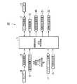
本実施の形態による車両用障害物検出装置10は、例えば図1に示すように、自車両に対する障害物を検出するためにCPU等を含む電子回路により構成された障害物検知・安全制御装置11(以下、単に、制御装置11と呼ぶ)と、レーダ制御部12と、レーダ13と、カメラ14と、画像処理部15と、車両状態量センサ16と、ナビゲーション装置17と、視線検出装置18と、制動装置19と、触覚的伝達装置20と、視覚的伝達装置21と、聴覚的伝達装置22とを備えて構成されている。Hereinafter, a vehicle obstacle detection device according to an embodiment of the present invention will be described with reference to the accompanying drawings.
As shown in FIG. 1, for example, the vehicle
レーダ13は、例えば自車両のボディのノーズ部や車室内のフロントウィンド近傍等に配置されており、制御装置11からレーダ制御部12へ入力される制御指令に応じたレーダ制御部12の制御により、レーザ光やミリ波等の発信信号を適宜の検知方向に向けて発信すると共に、この発信信号が自車両の外部の物体(検知対象物)によって反射されることで生じた反射信号を受信し、反射信号と発信信号とを混合してビート信号を発生させ、このビート信号の周波数f(「ビート周波数」)に基づいて、所定の検知エリア内の領域における検知対象物までの相対距離や相対速度や移動軌跡(または移動方向)等を算出し、これらの算出結果をレーダ制御部12を介して制御装置11へ出力する。なお、このレーダ13は、レーダ制御部12の制御により、複数の検知方向に向けて発信信号を発信可能である。
カメラ14は、例えば可視光領域や赤外線領域にて撮像可能なCCDカメラ等であって、制御装置11の制御により、適宜の検知方向での外界(例えば、他の車両や歩行者等の移動体や障害物や標識等)を撮影する。
そして、画像処理部15は、カメラ14から出力される画像を画像処理して、例えば自車両周辺の他の車両や歩行者等の移動体や障害物や標識等を検出し、これらの検出結果と共に、例えば自車両から認識した各物体までの相対距離の情報等を生成して制御装置11へ出力する。また、複数のカメラ14,…,14を搭載する車両において画像処理部15は、少なくとも2つのカメラ14,14の撮影画像に基づく三角測量法等により、他の車両や歩行者等の移動体や障害物等の位置を検出し、制御装置11へ出力する。The
The
Then, the
車両状態量センサ16は、例えば車速センサおよび舵角センサおよびジャイロセンサおよび傾斜センサおよび方向指示器の作動状態を検知するセンサ等を備えて構成され、各センサから出力される検出信号は制御装置11へ出力されている。
なお、車速センサは、例えば車輪の回転速度等に基づいて所定の単位処理時間毎における車両移動距離つまり自車両の速度を検出し、舵角センサは、例えばステアリングシャフト(図示略)に設けられたロータリエンコーダ等からなり、運転者が入力した操舵角度の方向と大きさを検出する。ジャイロセンサは、水平面内での自車両の向きや鉛直方向に対する傾斜角度(例えば、車両重心の上下方向軸回りの回転角であるヨー角等)および傾斜角度の変化量(例えば、ヨーレート)等を検出し、傾斜センサは、例えば車両重心の水平軸周りの回転角であるピッチ角およびピッチ角の変化量等を検出する。各センサの検出信号は、後述するように、制御装置11にて実行される自車両の進行軌跡や走行状態の予測動作等に利用される。The vehicle state quantity sensor 16 includes, for example, a vehicle speed sensor, a rudder angle sensor, a gyro sensor, a tilt sensor, a sensor that detects an operation state of a direction indicator, and the like, and a detection signal output from each sensor is a control device 11. Is output.
The vehicle speed sensor detects, for example, the vehicle travel distance per predetermined unit processing time, that is, the speed of the host vehicle based on, for example, the rotational speed of the wheels, and the steering angle sensor is provided on, for example, a steering shaft (not shown). It consists of a rotary encoder or the like, and detects the direction and magnitude of the steering angle input by the driver. The gyro sensor indicates the direction of the host vehicle in a horizontal plane, a tilt angle with respect to the vertical direction (for example, a yaw angle that is a rotation angle about the vertical axis of the center of gravity of the vehicle), a change amount of the tilt angle (for example, a yaw rate), and the like. The inclination sensor detects, for example, a pitch angle that is a rotation angle around the horizontal axis of the center of gravity of the vehicle, a change amount of the pitch angle, and the like. As will be described later, the detection signal of each sensor is used for the traveling trajectory of the host vehicle, the prediction operation of the running state, and the like executed by the control device 11.
ナビゲーション装置17は、例えば、自車両の現在位置を検出する現在位置算出部と、現在位置算出部にて算出された自車両の現在位置と予め記憶した道路地図データとに基づいてマップマッチングを行い、道路地図データ上における車両の位置を算出するマップマッチング処理部と、現在位置算出部にて算出された自車両の現在位置等を含む適宜の目的地から出発地までの経路を算出し、算出した経路に応じて経路誘導を行う経路算出・誘導部等とを備えて構成されている。
なお、現在位置検出部は、例えば人工衛星を利用して自車両の位置を測定するためのGPS(Global Positioning Systems)信号等の測位信号に基づく算出処理や、車両状態量センサ16のジャイロセンサおよび車速センサから出力される検出信号に基づく自律航法の算出処理や、自車両の外部の情報発信装置から発信される位置信号や例えば道路上に配置された基点マーカとの磁気作用等によって自車両の現在位置を算出する。For example, the
Note that the current position detection unit, for example, a calculation process based on a positioning signal such as a GPS (Global Positioning Systems) signal for measuring the position of the host vehicle using an artificial satellite, a gyro sensor of the vehicle state quantity sensor 16, and The calculation process of autonomous navigation based on the detection signal output from the vehicle speed sensor, the position signal transmitted from the information transmission device outside the host vehicle, or the magnetic action of the base point marker arranged on the road, etc. The current position is calculated.
なお、例えば所定の交差点を含む所定範囲内は情報発信装置(例えば、路上機)による情報提供のサービス区間とされ、自車両は、例えば交差点位置(交差点の中心位置等)から所定距離だけ手前位置の道路上に配置された基点マーカとの磁気相互作用等によって、あるいは、自車両に搭載されたカメラ14により得られる画像等に基づき、自車両がサービス区間へ進入したことを検知すると、サービス区間内での自車両の位置情報を外部から取得可能であると共に、例えば交差点に接続された道路を走行中の他の車両に関する対象物情報等を外部から受信可能である。 In addition, for example, a predetermined range including a predetermined intersection is a service section for providing information by an information transmission device (for example, a road machine), and the host vehicle is located at a position a predetermined distance from the intersection position (the center position of the intersection, for example). When it is detected that the host vehicle has entered the service section by magnetic interaction with the base marker placed on the road or on the basis of an image obtained by the
視線検出装置18は、例えば車室内に配置された赤外線照射装置および赤外線センサやCCDカメラ等を備え、運転者の顔や眼球に向けて照射した赤外線の反射を撮像して得た画像に基づき、運転者の視線方向を検出する。 The line-of-
制動装置19は、例えばブレーキ制御装置やスロットル制御装置等であって、制御装置11から入力される制御信号に応じて、例えばブレーキ液圧やスロットル開度等を制御して自車両に制動力を作用させ、走行時の減速や停車時の発進規制を行う。
触覚的伝達装置20は、例えばシートベルト装置や操舵制御装置等であって、制御装置11から入力される制御信号に応じて、例えばシートベルトに所定の張力を発生させて自車両の乗員が触覚的に知覚可能な締め付け力を作用させたり、例えばステアリングホイールに自車両の運転者が触覚的に知覚可能な振動(ステアリング振動)を発生させることによって、他の車両や歩行者等の移動体が自車両の走行の支障となる可能性が高いことを自車両の乗員に認識させる。
視覚的伝達装置21は、例えば表示装置等であって、制御装置11から入力される制御信号に応じて、例えば表示装置に所定の警報情報を表示したり、所定の警報灯を点滅させることによって、他の車両や歩行者等の移動体が自車両の走行の支障となる可能性が高いことを自車両の乗員に認識させる。
聴覚的伝達装置22は、例えば警報装置灯であって、制御装置11から入力される制御信号に応じて、例えば警報装置から所定の警報音等を出力することによって、他の車両や歩行者等の移動体が自車両の走行の支障となる可能性が高いことを自車両の乗員に認識させる。
なお、視覚的伝達装置21や聴覚的伝達装置22においては、自車両に対する他の車両や歩行者等の移動体の相対位置に応じて作動状態を変更することによって、相対位置に係る情報を自車両の乗員に認識させることができる。例えば聴覚的伝達装置22としてステレオスピーカを作動させる際には、左右の音量バランス等を変化させることで相対位置の情報を報知することができる。The braking device 19 is, for example, a brake control device, a throttle control device, or the like, and controls the brake fluid pressure, the throttle opening, etc. according to a control signal input from the control device 11, for example, and applies braking force to the host vehicle. Acts to decelerate when driving and to restrict starting when the vehicle stops.
The tactile transmission device 20 is, for example, a seat belt device, a steering control device, or the like, and generates a predetermined tension on the seat belt, for example, in response to a control signal input from the control device 11 so that the occupant of the host vehicle can sense the touch. When a moving body such as another vehicle or a pedestrian is applied by applying a perceptible tightening force or generating vibration (steering vibration) that can be perceived by the driver of the vehicle on the steering wheel, for example. Let the occupant of the own vehicle recognize that there is a high possibility of hindering the running of the own vehicle.
The
The
Note that the
制御装置11は、例えばナビゲーション装置17に記憶されている道路地図データや自車両の外部の情報発信装置から発信される位置信号や道路上に配置された基点マーカとの磁気作用により取得した情報に基づき、自車両の走行路の進行方向前方あるいは予測した進行軌跡上の道路構成として、少なくとも交差道路(例えば、交差点やT字路あるいは高速道路での合流地点等において自車両の走行路に交差する道路)の有無または車線数を検出する。そして、ナビゲーション装置17の現在位置算出部にて算出された自車両の現在位置と、ナビゲーション装置17の経路算出・誘導部にて算出された経路誘導データあるいは車両状態量センサ16にて検出された各種車両状態量(例えば、車速、操舵角度の方向および大きさ、方向指示器の作動状態)に基づき予測した自車両の進行軌跡(または移動方向)とに基づき、検出した道路構成における自車両の位置および移動方向に応じてレーダ13の検知方向およびカメラ14の撮像方向を設定する。
さらに、制御装置11は、検出した道路構成における自車両の位置および移動方向に加えて、視線検出装置18にて検出される運転者の視線方向に応じてレーダ13の検知方向およびカメラ14の撮像方向を設定する。
そして、レーダ13やカメラ14による検知結果に基づき、例えば他の車両や歩行者等の移動体や障害物等を検知した場合、これらの移動体や障害物が自車両の走行の支障となる可能性を算出し、この可能性に応じて制動装置19や触覚的伝達装置20や視覚的伝達装置21や聴覚的伝達装置22、さらには、エアバッグ等の乗員保護装置(図示略)を作動させる。The control device 11 uses, for example, road map data stored in the
Further, the control device 11 captures the detection direction of the
Based on the detection results of the
本実施の形態による車両用障害物検出装置10は上記構成を備えており、次に、この車両用障害物検出装置10の動作について説明する。
先ず、以下に、例えば交差点やT字路あるいは高速道路での合流地点等のように、自車両の走行路に交差する交差道路が存在する場合について説明する。The vehicle
First, a case will be described below where there is an intersection road that intersects the traveling path of the vehicle, such as an intersection, a T-shaped road, or a junction on an expressway.
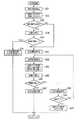
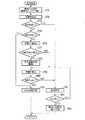
例えば図2に示すステップS01においては、道路構成検出処理として、例えばナビゲーション装置17に記憶されている道路地図データや自車両の外部の情報発信装置から発信される位置信号や道路上に配置された基点マーカとの磁気作用により取得した情報に基づき、少なくとも交差道路(例えば、交差点やT字路あるいは高速道路での合流地点等において自車両の走行路に交差する道路)の有無または車線数を検出する。
次に、ステップS02においては、例えばGPS信号等の測位信号に基づく算出処理や、車両状態量センサ16のジャイロセンサおよび車速センサから出力される検出信号に基づく自律航法の算出処理や、自車両の外部の情報発信装置から発信される位置信号や例えば道路上に配置された基点マーカとの磁気作用等によって自車両の現在位置を算出する。
次に、ステップS03においては、車両状態量センサ16の各センサから出力される検出信号に基づき、自車両の走行状態、例えば停止状態や、右折または左折時の旋回状態等を検出する。For example, in step S01 shown in FIG. 2, as road configuration detection processing, for example, road map data stored in the
Next, in step S02, for example, calculation processing based on a positioning signal such as a GPS signal, calculation processing of autonomous navigation based on detection signals output from the gyro sensor and the vehicle speed sensor of the vehicle state quantity sensor 16, The current position of the host vehicle is calculated from a position signal transmitted from an external information transmission device or a magnetic action with a base marker placed on a road, for example.
Next, in step S03, based on the detection signal output from each sensor of the vehicle state quantity sensor 16, the running state of the host vehicle, for example, the stop state, the turning state at the time of turning right or left, and the like are detected.
次に、ステップS04においては、自車両の走行路の進行方向前方あるいは予測した進行軌跡上において、交差道路が存在することを検出したか否かを判定する。
この判定結果が「NO」の場合には、一連の処理を終了する。
一方、この判定結果が「YES」の場合には、ステップS05に進む。
ステップS05においては、ナビゲーション装置17の経路算出・誘導部にて算出された経路誘導データあるいは車両状態量センサ16にて検出された各種車両状態量(例えば、車速、操舵角度の方向および大きさ、方向指示器の作動状態)に基づき、交差道路が存在する領域での自車両の進行方向を推定する。
そして、ステップS06においては、交差道路が存在する領域を、この時点での走行路に沿って直進すると推定したか否かを判定し、この判定結果が「YES」の場合には、ステップS07に進み、後述する直進処理を実行し、一連の処理を終了する。
一方、ステップS06での判定結果が「NO」の場合には、ステップS08に進む。
そして、ステップS08においては、交差道路が存在する領域を、右折すると推定したか否かを判定し、この判定結果が「YES」の場合には、ステップS09に進み、後述する右折処理を実行し、一連の処理を終了する。
一方、ステップS08での判定結果が「NO」の場合には、ステップS10に進む。
そして、ステップS10においては、交差道路が存在する領域を、左折すると推定したか否かを判定し、この判定結果が「YES」の場合には、ステップS11に進み、後述する左折処理を実行し、一連の処理を終了する。
一方、ステップS10での判定結果が「NO」の場合には、ステップS12に進む。
そして、ステップS12においては、交差道路が存在する領域を、合流すると推定したか否かを判定し、この判定結果が「YES」の場合には、ステップS13に進み、後述する合流処理を実行し、一連の処理を終了する。
一方、ステップS12での判定結果が「NO」の場合には、一連の処理を終了する。Next, in step S04, it is determined whether or not it is detected that an intersection road exists on the front of the traveling path of the host vehicle or on the predicted traveling locus.
When the determination result is “NO”, the series of processes is terminated.
On the other hand, if this determination is “YES”, the flow proceeds to step S 05.
In step S05, the route guidance data calculated by the route calculation / guidance unit of the
In step S06, it is determined whether or not it is estimated that the area where the intersection road exists is going straight along the traveling road at this time. If the determination result is “YES”, the process proceeds to step S07. The process proceeds to execute a straight-ahead process, which will be described later, and the series of processes ends.
On the other hand, if the determination result in step S06 is “NO”, the process proceeds to step S08.
In step S08, it is determined whether or not it is estimated that the area where the intersection road exists is to turn right. If the determination result is “YES”, the process proceeds to step S09, and a right turn process described later is executed. Then, a series of processing is completed.
On the other hand, if the determination result in step S08 is “NO”, the process proceeds to step S10.
In step S10, it is determined whether or not it is estimated that the area where the intersection road exists is left-turned. If the determination result is “YES”, the process proceeds to step S11, and a left-turn process described later is executed. Then, a series of processing is completed.
On the other hand, if the determination result in step S10 is “NO”, the process proceeds to step S12.
In step S12, it is determined whether or not it is estimated that the area where the intersection road exists is merged. If the determination result is “YES”, the process proceeds to step S13, and a merge process described later is executed. Then, a series of processing is completed.
On the other hand, if the determination result in step S12 is “NO”, the series of processing ends.
以下に、上述したステップS07における直進処理について図3および図4を参照して説明する。
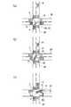
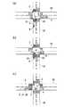
例えば図4(a)に示すように、自車両Pの走行路SPの前方に交差道路SAが走行路SPに交差する交差点Cが存在し、この交差点Cを自車両Pが直進する場合において、自車両Pが交差点Cに進入するより以前の時点では、レーダ13を構成する複数、例えば2つの左方レーダおよび右方レーダの各検知方向D1,D2は自車両Pの進行方向Qと同方向(つまり、進行方向前方)に設定され、これらの各検知方向D1,D2は自車両Pの運転者の視線方向Rと同方向となっている。
この状態において、先ず、例えば図3に示すステップS21では、交差道路が存在する領域での自車両の位置および走行状態に応じて、レーダ13の検知方向を交差道路の交差方向に設定する。これにより、例えば図4(b)に示すように、自車両Pが交差点Cに進入する際に、運転者の視線方向Rが直進方向に設定されている状態であっても、左方レーダの検知方向D1が自車両Pの左側方に設定され、右方レーダの検知方向D2が自車両Pの右側方に設定され、交差道路SAを交差点Cに向かい左側および右側から接近する他の車両A1,A2が検知可能となる。Hereinafter, the straight-ahead process in step S07 described above will be described with reference to FIG. 3 and FIG.
For example, as shown in FIG. 4A, in the case where there is an intersection C where the intersection road SA intersects the traveling road SP in front of the traveling road SP of the own vehicle P, and the own vehicle P goes straight through the intersection C, Before the time when the host vehicle P enters the intersection C, the detection directions D1 and D2 of a plurality of, for example, two left radars and right radars constituting the
In this state, first, in step S21 shown in FIG. 3, for example, the detection direction of the
次に、ステップS22においては、例えばレーダ13により検知した検知対象物に対する相対距離や相対速度や移動軌跡(または移動方向)等の検知結果に基づき、検知対象物が自車両の走行の支障となる可能性(危険性)を推定する。
そして、ステップS23においては、検知対象物が自車両の走行の支障となる可能性が高い(例えば、所定値以上)か否かを判定する。
この判定結果が「YES」の場合には、ステップS24に進み、例えば制動装置19を作動させて、交差道路が存在する領域を自車両が通過するタイミングをずらしたり、自車両を停止させたり、触覚的伝達装置20や視覚的伝達装置21や聴覚的伝達装置22を作動させて運転者の注意を促したり、さらには、エアバッグ等の乗員保護装置を作動させて、一連の処理を終了する。
一方、この判定結果が「NO」の場合には、ステップS25に進み、直進を許可する。
そして、ステップS26においては、交差道路が存在する領域の通過が完了したか否かを判定する。
ステップS26での判定結果が「NO」の場合には、上述したステップS22に戻る。
一方、ステップS26での判定結果が「YES」の場合には、ステップS27に進み、レーダ13の検知方向を自車両の進行方向に設定して、一連の処理を終了する。
これにより、例えば図4(c)に示すように、自車両Pが交差点Cを通過した後に、左方レーダの検知方向D1および右方レーダの検知方向D2が運転者の視線方向Rと同方向に設定される。Next, in step S22, for example, based on detection results such as a relative distance, a relative speed, a movement trajectory (or movement direction), and the like with respect to the detection object detected by the
Then, in step S23, it is determined whether or not the detection target object is likely to obstruct travel of the host vehicle (for example, a predetermined value or more).
If this determination is “YES”, the flow proceeds to step S24, for example, the braking device 19 is operated to shift the timing at which the host vehicle passes through the area where the crossing road exists, to stop the host vehicle, The tactile transmission device 20, the
On the other hand, if this determination is “NO”, the flow proceeds to step S25, and straight traveling is permitted.
In step S26, it is determined whether or not the passage of the area where the intersection road exists is completed.
If the determination result in step S26 is “NO”, the process returns to step S22 described above.
On the other hand, if the determination result in step S26 is “YES”, the process proceeds to step S27, the detection direction of the
Thus, for example, as shown in FIG. 4C, after the host vehicle P passes through the intersection C, the left radar detection direction D1 and the right radar detection direction D2 are the same as the driver's line-of-sight direction R. Set to
以下に、上述したステップS09における右折処理について図5から図7を参照して説明する。
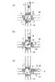
例えば図6(a),図7(a)に示すように、例えば自車両Pの走行路SPの前方に交差道路SAが走行路SPに交差する交差点Cが存在し、この交差点Cを自車両Pが右折する場合において、先ず、例えば図5に示すステップS31では、自車両の運転者の視線方向を検出する。
次に、ステップS32においては、交差道路が存在する領域での自車両の位置および走行状態および運転者の視線方向に応じて、レーダ13の検知方向を、少なくとも運転者の視線方向以外の方向に設定する。これにより、例えば図6(a)に示すように、自車両Pが走行路SPに沿って交差点Cに進入する際に、運転者の視線方向Rが自車両Pの進行方向Q前方であって対向車線を走行する対向車両Aが存在する方向に設定されており、交差点C内で自車両Pが減速もしくは停止するまでの間は、レーダ13を構成する複数、例えば2つの左方レーダおよび右方レーダの各検知方向D1,D2は、視線方向R以外の方向、例えば自車両Pの右折方向に設定される。また、例えば図7(a)に示すように、自車両Pが走行路SPに沿って交差点Cに進入する際に、運転者の視線方向Rが交差道路SAの方向に設定されている場合には、左方レーダおよび右方レーダの各検知方向D1,D2は、対向車線を走行する対向車両Aが存在する方向に設定される。Hereinafter, the right turn process in step S09 described above will be described with reference to FIGS.
For example, as shown in FIGS. 6A and 7A, for example, there is an intersection C where the intersection road SA intersects the traveling road SP in front of the traveling road SP of the own vehicle P. When P turns right, first, for example, in step S31 shown in FIG. 5, the line-of-sight direction of the driver of the host vehicle is detected.
Next, in step S32, the detection direction of the
次に、ステップS33においては、レーダ13により対向車両を検知したか否かを判定する。
この判定結果が「NO」の場合には、後述するステップS37に進む。
一方、この判定結果が「YES」の場合には、ステップS34に進み、例えばレーダ13により検知した対向車両に対する相対距離や相対速度や移動軌跡(または移動方向)等の検知結果に基づき、対向車両が自車両の右折動作の支障となる可能性(危険性)を推定する。
そして、ステップS35においては、対向車両が自車両の右折動作の支障となる可能性が高い(例えば、所定値以上)か否かを判定する。
この判定結果が「YES」の場合には、ステップS36に進み、例えば制動装置19を作動させて、自車両が対向車線を横切って右折するタイミングをずらしたり、停止状態の自車両の発進を規制したり、触覚的伝達装置20や視覚的伝達装置21や聴覚的伝達装置22を作動させて運転者の注意を促したり、さらには、エアバッグ等の乗員保護装置を作動させて、一連の処理を終了する。
一方、この判定結果が「NO」の場合には、ステップS37に進み、右折の開始を許可する。Next, in step S33, it is determined whether the oncoming vehicle is detected by the
If this determination is “NO”, the flow proceeds to step
On the other hand, if this determination is “YES”, the flow proceeds to step S 34, and the oncoming vehicle is detected based on the detection results of the relative distance, relative speed, movement locus (or movement direction), etc., with respect to the oncoming vehicle detected by the
In step S35, it is determined whether or not the oncoming vehicle is likely to interfere with the right turn operation of the host vehicle (for example, a predetermined value or more).
If this determination is “YES”, the flow proceeds to step
On the other hand, if this determination is “NO”, the flow proceeds to step
次に、ステップS38においては、車両状態量センサ16の各センサから出力される検出信号に基づき、自車両の旋回状態、例えば車速や操舵角度の大きさ等を検出する。
そして、ステップS39においては、検出した自車両の旋回状態、さらには、運転者の視線方向に応じて、レーダ13の検知方向を変更する。このとき、レーダ13の検知方向を少なくとも旋回内側の側方または旋回外側の側方に設定する。これにより、例えば図6(b),(c)に示すように、運転者の視線方向Rが対向車両Aが存在する方向に設定されている場合には、左方レーダおよび右方レーダの各検知方向D1,D2は、自車両Pが旋回後に走行する交差道路SAの横断歩道およびこの横断歩道周辺の領域に向かう方向に設定される。この場合には、横断歩道を通行する歩行者や自転車等の移動体が検知可能となる。
また、例えば図7(b)に示すように、運転者の視線方向Rが、自車両Pが旋回後に走行する交差道路SAの横断歩道およびこの横断歩道周辺の領域に向かう方向に設定されている場合には、左方レーダの検知方向D1は対向車両Aが存在する方向(つまり、旋回外側の側方)に設定され、右方レーダの検知方向D2は、自車両Pが旋回後に走行する交差道路SAの横断歩道およびこの横断歩道周辺の領域であって運転者の視線方向R以外の方向(例えば、旋回内側の側方)に設定される。この場合には、運転者によって認識されずに横断歩道を通行する歩行者や自転車等の移動体に加えて、既に運転者やレーダ13により検知されている対向車両Aの後方、つまり対向車両Aによって死角となる領域から、この対向車両Aを追い越して交差点Cに進入する他の車両Bが検知可能となる。Next, in step S38, based on the detection signal output from each sensor of the vehicle state quantity sensor 16, the turning state of the host vehicle, for example, the vehicle speed, the magnitude of the steering angle, and the like are detected.
In step S39, the detection direction of the
For example, as shown in FIG. 7B, the driver's line-of-sight direction R is set in a direction toward the pedestrian crossing of the crossing road SA on which the host vehicle P travels after turning and the area around the pedestrian crossing. In this case, the detection direction D1 of the left radar is set to the direction in which the oncoming vehicle A exists (that is, the side outside the turn), and the detection direction D2 of the right radar is an intersection where the host vehicle P travels after the turn. The pedestrian crossing of the road SA and the area around the pedestrian crossing are set in a direction other than the driver's line-of-sight direction R (for example, the side inside the turn). In this case, in addition to a moving body such as a pedestrian or a bicycle that passes through a pedestrian crossing without being recognized by the driver, the rear of the oncoming vehicle A already detected by the driver or the
次に、ステップS40においては、例えばレーダ13により検知した検知対象物に対する相対距離や相対速度や移動軌跡(または移動方向)等の検知結果に基づき、検知対象物が自車両の走行の支障となる可能性(危険性)を推定する。
そして、ステップS41においては、検知対象物が自車両の走行の支障となる可能性が高い(例えば、所定値以上)か否かを判定する。
この判定結果が「YES」の場合には、ステップS42に進み、例えば制動装置19を作動させて、自車両が対向車線を横切って右折するタイミングをずらしたり、自車両を停止させたり、触覚的伝達装置20や視覚的伝達装置21や聴覚的伝達装置22を作動させて運転者の注意を促したり、さらには、エアバッグ等の乗員保護装置を作動させて、一連の処理を終了する。
一方、この判定結果が「NO」の場合には、ステップS43に進み、右折の旋回動作の継続を許可する。
そして、ステップS44においては、右折が完了したか否かを判定する。
ステップS44での判定結果が「NO」の場合には、上述したステップS38に戻る。
一方、ステップS44での判定結果が「YES」の場合には、ステップS45に進み、レーダ13の検知方向を自車両の進行方向に設定して、一連の処理を終了する。
これにより、例えば図7(c)に示すように、自車両Pが交差点Cを通過した後に、左方レーダの検知方向D1および右方レーダの検知方向D2が運転者の視線方向Rと同方向に設定される。Next, in step S40, for example, based on detection results such as a relative distance, a relative speed, a movement trajectory (or movement direction), and the like with respect to the detection object detected by the
In step S41, it is determined whether or not the detection target object is highly likely to interfere with traveling of the host vehicle (for example, a predetermined value or more).
If this determination is “YES”, the flow proceeds to step
On the other hand, if this determination is “NO”, the flow proceeds to step S 43, and continuation of the right turn turning operation is permitted.
In step S44, it is determined whether the right turn is completed.
If the determination result in step S44 is “NO”, the process returns to step S38 described above.
On the other hand, if the determination result in step S44 is “YES”, the process proceeds to step S45, the detection direction of the
Thus, for example, as shown in FIG. 7C, after the host vehicle P passes through the intersection C, the left radar detection direction D1 and the right radar detection direction D2 are the same as the driver's line-of-sight direction R. Set to
以下に、上述したステップS11における左折処理について図8および図9を参照して説明する。
例えば図9(a)に示すように、自車両Pの走行路SPの前方に交差道路SAが走行路SPに交差する交差点Cが存在し、この交差点Cを自車両Pが左折する場合において、自車両Pが交差点Cに進入するより以前の時点では、レーダ13を構成する複数、例えば2つの左方レーダおよび右方レーダの各検知方向D1,D2は自車両Pの進行方向Qと同方向(つまり、進行方向前方)に設定され、これらの各検知方向D1,D2は自車両Pの運転者の視線方向Rと同方向となっている。
この状態において、先ず、例えば図8に示すステップS51では、交差道路が存在する領域での自車両の位置および走行状態に応じて、レーダ13の検知方向を交差道路の交差方向に設定する。これにより、例えば図9(a)に示すように、自車両Pが交差点Cに進入する際に、運転者の視線方向Rが直進方向に設定されている状態であっても、左方レーダの検知方向D1が自車両Pの左側方に設定され、右方レーダの検知方向D2が自車両Pの右側方に設定され、交差道路SAを走行して交差点Cに向かい接近する他の車両Aが検知可能となる。Below, the left turn process in step S11 mentioned above is demonstrated with reference to FIG. 8 and FIG.
For example, as shown in FIG. 9A, when there is an intersection C where the intersection road SA intersects the traveling road SP in front of the traveling road SP of the own vehicle P, and the own vehicle P makes a left turn at this intersection C, Before the time when the host vehicle P enters the intersection C, the detection directions D1 and D2 of a plurality of, for example, two left radars and right radars constituting the
In this state, first, in step S51 shown in FIG. 8, for example, the detection direction of the
次に、ステップS52においては、例えばレーダ13により検知した検知対象物に対する相対距離や相対速度や移動軌跡(または移動方向)等の検知結果に基づき、検知対象物が自車両の左折動作の支障となる可能性(危険性)を推定する。
そして、ステップS53においては、検知対象物が自車両の走行の支障となる可能性が高い(例えば、所定値以上)か否かを判定する。
この判定結果が「YES」の場合には、ステップS54に進み、例えば制動装置19を作動させて、自車両が左折するタイミングをずらしたり、自車両を停止させたり、触覚的伝達装置20や視覚的伝達装置21や聴覚的伝達装置22を作動させて運転者の注意を促し、一連の処理を終了する。
一方、この判定結果が「NO」の場合には、ステップS55に進み、左折の開始を許可する。Next, in step S52, for example, based on the detection results such as the relative distance, relative speed, movement trajectory (or movement direction), etc. with respect to the detection object detected by the
In step S53, it is determined whether or not the detection target object is likely to obstruct travel of the host vehicle (for example, a predetermined value or more).
If this determination is “YES”, the flow proceeds to step S 54, for example, the braking device 19 is operated to shift the timing at which the host vehicle turns to the left, the host vehicle is stopped, the tactile transmission device 20 or the visual The
On the other hand, if this determination is “NO”, the flow proceeds to step S55, and the start of a left turn is permitted.
次に、ステップS56においては、車両状態量センサ16の各センサから出力される検出信号に基づき、自車両の旋回状態、例えば車速や操舵角度の大きさ等を検出する。
さらに、ステップS57においては、自車両の運転者の視線方向を検出する。
そして、ステップS58においては、検出した自車両の旋回状態、さらには、運転者の視線方向に応じて、レーダ13の検知方向を変更する。このとき、レーダ13の検知方向を運転者の視線方向以外であって、少なくとも旋回内側あるいは旋回外側の後方および側方の何れかに設定する。これにより、例えば図9(b)に示すように、運転者の視線方向Rが自車両Pの移動方向前方の横断歩道およびこの横断歩道周辺の領域に向かう方向に設定されている場合には、左方レーダの検知方向D1は自車両Pの後方から接近あるいは自車両Pの左側方を通過する他の車両Bが存在する方向(つまり、旋回内側の後方または側方)に設定され、右方レーダの検知方向D2は、自車両Pが旋回後に走行する交差道路SAを走行して交差点Cに接近する他の車両Aが存在する方向(つまり、旋回外側の後方または側方)に設定される。Next, in step S56, based on the detection signal output from each sensor of the vehicle state quantity sensor 16, the turning state of the host vehicle, for example, the vehicle speed, the magnitude of the steering angle, and the like are detected.
Furthermore, in step S57, the line-of-sight direction of the driver of the host vehicle is detected.
In step S58, the detection direction of the
次に、ステップS59においては、例えばレーダ13により検知した検知対象物に対する相対距離や相対速度や移動軌跡(または移動方向)等の検知結果に基づき、検知対象物が自車両の走行の支障となる可能性(危険性)を推定する。
そして、ステップS60においては、検知対象物が自車両の走行の支障となる可能性が高い(例えば、所定値以上)か否かを判定する。
この判定結果が「YES」の場合には、ステップS61に進み、例えば制動装置19を作動させて、自車両が左折するタイミングをずらしたり、自車両を停止させたり、触覚的伝達装置20や視覚的伝達装置21や聴覚的伝達装置22を作動させて運転者の注意を促したり、さらには、エアバッグ等の乗員保護装置を作動させて、一連の処理を終了する。
一方、この判定結果が「NO」の場合には、ステップS62に進み、左折の旋回動作の継続を許可する。
そして、ステップS63においては、左折が完了したか否かを判定する。
ステップS63での判定結果が「NO」の場合には、上述したステップS56に戻る。
一方、ステップS63での判定結果が「YES」の場合には、ステップS64に進み、レーダ13の検知方向を自車両の進行方向に設定して、一連の処理を終了する。
これにより、例えば図9(c)に示すように、自車両Pが交差点Cを通過した後に、左方レーダの検知方向D1および右方レーダの検知方向D2が運転者の視線方向Rと同方向に設定される。Next, in step S59, for example, based on detection results such as a relative distance, a relative speed, a movement trajectory (or a movement direction), etc., with respect to the detection object detected by the
In step S60, it is determined whether or not the detection target object is likely to obstruct travel of the host vehicle (for example, a predetermined value or more).
If this determination is “YES”, the flow proceeds to step S61, for example, the braking device 19 is operated to shift the timing at which the host vehicle turns to the left, the host vehicle is stopped, the tactile transmission device 20 or the visual The
On the other hand, if this determination is “NO”, the flow proceeds to step
In step S63, it is determined whether the left turn is completed.
If the determination result in step S63 is “NO”, the process returns to step S56 described above.
On the other hand, if the determination result in step S63 is “YES”, the process proceeds to step S64, the detection direction of the
Thus, for example, as shown in FIG. 9C, after the host vehicle P passes through the intersection C, the left radar detection direction D1 and the right radar detection direction D2 are the same as the driver's line-of-sight direction R. Set to
以下に、上述したステップS13における合流処理について図10および図11を参照して説明する。
例えば図11(a)に示すように、自車両Pの走行路SPの前方に、この走行路SPが合流するようにして接続される交差道路SAが存在し、互いの走行方向が略鋭角に交差するようにして接続される走行路SPと交差道路SAとの合流位置Eにおいて自車両Pが交差道路SAに進入する場合において、自車両Pが合流位置Eに向かい接近している状態では、先ず、例えば図10に示すステップS71において、交差道路が存在する領域での自車両の位置および走行状態に応じて、レーダ13の検知方向を、少なくとも交差道路を走行する車両を検出可能な方向、例えば自車両から見て交差道路が存在する側での自車両の側方および後方に設定する。これにより、例えば図11(a)に示すように、自車両Pが合流位置Eに接近する際に、運転者の視線方向Rが進行方向Qに設定されている状態であっても、左方レーダの検知方向D1が自車両Pの進行方向Qに設定され、右方レーダの検知方向D2が自車両Pの右側方から右後方の方向に設定され、自車両Pの走行路SPの前方を走行する先行車両(図示略)に加えて、交差道路SAを走行して合流位置Eに向かい接近する他の車両Aが検知可能となる。Hereinafter, the merging process in step S13 described above will be described with reference to FIGS.
For example, as shown in FIG. 11 (a), there is an intersection road SA that is connected in such a way that the traveling road SP merges in front of the traveling road SP of the host vehicle P, and the traveling directions thereof are substantially acute. When the host vehicle P enters the intersection road SA at the junction position E between the traveling road SP and the intersection road SA that are connected so as to intersect, in a state where the host vehicle P is approaching the junction position E, First, for example, in step S71 shown in FIG. 10, the detection direction of the
次に、ステップS72においては、例えばレーダ13により検知した検知対象物に対する相対距離や相対速度や移動軌跡(または移動方向)等の検知結果に基づき、検知対象物が自車両の合流動作の支障となる可能性(危険性)を推定する。
そして、ステップS73においては、検知対象物が自車両の走行の支障となる可能性が低い(例えば、所定値未満)か否かを判定する。
この判定結果が「YES」の場合には、後述するステップS81に進む。
一方、この判定結果が「NO」の場合には、ステップS74に進む。
そして、ステップS74においては、検知対象物が自車両の走行の支障となる可能性が高い(例えば、所定値以上)か否かを判定する。
ステップS74の判定結果が「YES」の場合には、ステップS75に進み、例えば制動装置19を作動させて、自車両が合流するタイミングをずらしたり、自車両を停止させたり、触覚的伝達装置20や視覚的伝達装置21や聴覚的伝達装置22を作動させて運転者の注意を促したり、さらには、エアバッグ等の乗員保護装置を作動させて、一連の処理を終了する。
一方、ステップS74の判定結果が「NO」の場合、つまり検知対象物が自車両の走行の支障となる可能性が中程度である場合には、ステップS76に進む。Next, in step S72, for example, based on the detection results such as the relative distance, relative speed, and movement trajectory (or movement direction) with respect to the detection object detected by the
In step S73, it is determined whether or not the detection target object is unlikely to interfere with the traveling of the host vehicle (for example, less than a predetermined value).
If this determination is “YES”, the flow proceeds to step
On the other hand, if this determination is “NO”, the flow proceeds to step
In step S74, it is determined whether or not the detection target object is likely to obstruct travel of the host vehicle (for example, a predetermined value or more).
If the determination result in step S74 is “YES”, the process proceeds to step S75, and for example, the braking device 19 is operated to shift the timing at which the host vehicle joins, stop the host vehicle, or the tactile transmission device 20. Then, the
On the other hand, if the determination result in step S74 is “NO”, that is, if there is a moderate possibility that the detection target will interfere with the traveling of the host vehicle, the process proceeds to step S76.
さらに、ステップS76においては、自車両の運転者の視線方向を検出する。
そして、ステップS77においては、検出した視線方向が適切であるか否かを判定する。
ここでは、例えば自車両の位置や走行状態の検出結果に応じて、検知すべき方向を優先度と共に設定し、検出した視線方向が優先度の高い検知すべき方向と同方向に設定されているか否かを判定する。
この判定結果が「YES」の場合、例えば図11(c)に示すように、自車両Pが合流位置Eに進入する際に運転者の視線方向Rが右方レーダの検知方向D2と同方向である自車両Pの右側方から右後方の方向に設定されている場合には、後述するステップS79に進む。
一方、この判定結果が「NO」の場合、例えば図11(b)に示すように、自車両Pが合流位置Eに進入する際に運転者の視線方向Rが右方レーダの検知方向D2とは異なる自車両Pの進行方向Qに設定されている場合には、ステップS78に進み、例えば触覚的伝達装置20や視覚的伝達装置21や聴覚的伝達装置22を作動させて運転者の注意を促す。
そして、ステップS79においては、例えばレーダ13により検知した検知対象物に対する相対距離や相対速度や移動軌跡(または移動方向)等の検知結果に加えて、検出した自車両の位置や走行状態、さらには、運転者の視線方向に基づき、検知対象物が自車両の合流動作の支障となる可能性(危険性)を推定する。
そして、ステップS80においては、検知対象物が自車両の走行の支障となる可能性が高い(例えば、所定値以上)か否かを判定する。
ステップS80の判定結果が「YES」の場合には、ステップS75に進み、例えば制動装置19を作動させて、自車両が合流するタイミングをずらしたり、自車両を停止させたり、触覚的伝達装置20や視覚的伝達装置21や聴覚的伝達装置22を作動させて運転者の注意を促したり、さらには、エアバッグ等の乗員保護装置を作動させて、一連の処理を終了する。
一方、ステップS80の判定結果が「NO」の場合には、ステップS81に進み、合流動作の実行を許可する。
そして、ステップS82においては、合流が完了したか否かを判定する。
ステップS82での判定結果が「NO」の場合には、上述したステップS79に戻る。
一方、ステップS82での判定結果が「YES」の場合には、ステップS83に進み、レーダ13の検知方向を自車両の進行方向に設定して、一連の処理を終了する。Further, in step S76, the line-of-sight direction of the driver of the host vehicle is detected.
In step S77, it is determined whether or not the detected gaze direction is appropriate.
Here, for example, depending on the detection result of the position of the host vehicle and the running state, the direction to be detected is set together with the priority, and is the detected gaze direction set to the same direction as the direction to be detected with a high priority? Determine whether or not.
When the determination result is “YES”, for example, as shown in FIG. 11C, when the host vehicle P enters the merge position E, the driver's line-of-sight direction R is the same as the right-side radar detection direction D2. Is set in the direction from the right side to the right rear side of the host vehicle P, the process proceeds to step S79 described later.
On the other hand, when the determination result is “NO”, for example, as shown in FIG. 11B, when the host vehicle P enters the merge position E, the driver's line-of-sight direction R is the right radar detection direction D2. Is set in the traveling direction Q of the own vehicle P, the process proceeds to step S78, and for example, the tactile transmission device 20, the
In step S79, for example, in addition to detection results such as a relative distance, a relative speed, a movement trajectory (or a movement direction) with respect to the detection object detected by the
In step S80, it is determined whether or not the detection target object is likely to obstruct travel of the host vehicle (for example, a predetermined value or more).
If the determination result in step S80 is “YES”, the process proceeds to step S75, for example, the braking device 19 is operated to shift the timing at which the host vehicle joins, the host vehicle is stopped, the tactile transmission device 20 Then, the
On the other hand, if the decision result in the step S80 is “NO”, the process advances to a step S81 to permit execution of the merging operation.
In step S82, it is determined whether or not the merging is completed.
If the determination result in step S82 is “NO”, the process returns to step S79 described above.
On the other hand, if the determination result in step S82 is “YES”, the process proceeds to step S83, the detection direction of the
また、以下に、片側複数車線の走行路において車線変更を実行する場合について図12および図13を参照して説明する。
例えば図12に示すステップS01においては、道路構成検出処理として、例えばナビゲーション装置17に記憶されている道路地図データや自車両の外部の情報発信装置から発信される位置信号や道路上に配置された基点マーカとの磁気作用により取得した情報に基づき、少なくとも交差道路(例えば、交差点やT字路あるいは高速道路での合流地点等において自車両の走行路に交差する道路)の有無または車線数を検出する。
次に、ステップS02においては、例えばGPS信号等の測位信号に基づく算出処理や、車両状態量センサ16のジャイロセンサおよび車速センサから出力される検出信号に基づく自律航法の算出処理や、自車両の外部の情報発信装置から発信される位置信号や例えば道路上に配置された基点マーカとの磁気作用等によって自車両の現在位置(例えば、片側複数車線の走行路において自車両が走行中の車線等)を算出する。
次に、ステップS03においては、車両状態量センサ16の各センサから出力される検出信号に基づき、自車両の走行状態を検出する。Moreover, the case where a lane change is performed in the traveling path of one side multiple lanes is demonstrated below with reference to FIG. 12 and FIG.
For example, in step S01 shown in FIG. 12, as road configuration detection processing, for example, road map data stored in the
Next, in step S02, for example, calculation processing based on a positioning signal such as a GPS signal, calculation processing of autonomous navigation based on detection signals output from the gyro sensor and the vehicle speed sensor of the vehicle state quantity sensor 16, The current position of the host vehicle (for example, the lane in which the host vehicle is traveling on the traveling road of multiple lanes on one side, etc.) by a position signal transmitted from an external information transmitting device or a magnetic action with a base marker arranged on the road, for example ) Is calculated.
Next, in step S03, the traveling state of the host vehicle is detected based on detection signals output from the sensors of the vehicle state quantity sensor 16.
次に、ステップS91においては、自車両の走行路が複数車線を有するか否かを判定する。
この判定結果が「NO」の場合には、一連の処理を終了する。
一方、この判定結果が「YES」の場合には、ステップS92に進む。
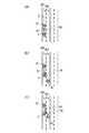
ステップS92においては、運転者が車線変更を実行する意志を有するか否かを判定する。ここでは、例えば図13(a)に示すように、自車両Pが走行中の車線SP1に対して、車線変更可能な車線SP2が存在する側の方向指示器が作動している状態か否かを判定する。
ステップS92の判定結果が「NO」の場合には、一連の処理を終了する。
一方、ステップS92の判定結果が「YES」の場合には、ステップS93に進む。
ステップS93においては、自車両の走行状態に応じてレーダ13の検知方向を、少なくとも車線変更後に自車両が走行する車線(変更車線)を走行する他の車両を検出可能な方向、例えば自車両から見て変更車線が存在する側での自車両の側方および後方に設定する。これにより、例えば図13(b)に示すように、自車両Pが走行中の車線SP1の前方の先行車両A1を追い越すようにして、右側に存在する追い越し車線SP2に車線変更する際に、左方レーダの検知方向D1が自車両Pの進行方向Q前方に設定され、右方レーダの検知方向D2が自車両Pの右側方から右後方の方向に設定され、先行車両A1に加えて、追い越し車線SP2を走行中の他の車両A2が検知可能となる。Next, in step S91, it is determined whether the traveling path of the host vehicle has a plurality of lanes.
When the determination result is “NO”, the series of processes is terminated.
On the other hand, if this determination is “YES”, the flow proceeds to step
In step S92, it is determined whether or not the driver is willing to change lanes. Here, for example, as shown in FIG. 13 (a), whether or not the direction indicator on the side where the lane SP2 where the lane change is possible exists is operating with respect to the lane SP1 in which the host vehicle P is traveling. Determine.
If the determination result in step S92 is “NO”, the series of processes is terminated.
On the other hand, if the determination result of step S92 is “YES”, the process proceeds to step S93.
In step S93, the detection direction of the
次に、ステップS94においては、例えばレーダ13により検知した検知対象物に対する相対距離や相対速度や移動軌跡(または移動方向)等の検知結果に基づき、検知対象物が自車両の車線変更動作の支障となる可能性(危険性)を推定する。
そして、ステップS95においては、検知対象物が自車両の走行の支障となる可能性が低い(例えば、所定値未満)か否かを判定する。
この判定結果が「YES」の場合には、後述するステップS101に進む。
一方、この判定結果が「NO」の場合には、ステップS96に進む。
そして、ステップS96においては、検知対象物が自車両の走行の支障となる可能性が高い(例えば、所定値以上)か否かを判定する。
ステップS96の判定結果が「YES」の場合には、ステップS97に進み、例えば制動装置19を作動させて、自車両が車線変更を実行するタイミングをずらしたり、触覚的伝達装置20や視覚的伝達装置21や聴覚的伝達装置22を作動させて運転者の注意を促したり、さらには、エアバッグ等の乗員保護装置を作動させて、一連の処理を終了する。
一方、ステップS96の判定結果が「NO」の場合、つまり検知対象物が自車両の走行の支障となる可能性が中程度である場合には、ステップS98に進む。Next, in step S94, for example, the detected object interferes with the lane change operation of the host vehicle based on the detection results such as the relative distance, relative speed, and movement locus (or moving direction) with respect to the detected object detected by the
In step S95, it is determined whether or not the detection target object is unlikely to interfere with the traveling of the host vehicle (for example, less than a predetermined value).
If this determination is “YES”, the flow proceeds to step
On the other hand, if this determination is “NO”, the flow proceeds to step
In step S96, it is determined whether or not the detection target object is likely to obstruct travel of the host vehicle (for example, a predetermined value or more).
If the determination result in step S96 is “YES”, the process proceeds to step S97, for example, the braking device 19 is operated to shift the timing at which the host vehicle changes lanes, or the tactile transmission device 20 or visual transmission is performed. The
On the other hand, if the determination result in step S96 is “NO”, that is, if the possibility that the detection target will interfere with the traveling of the host vehicle is moderate, the process proceeds to step S98.
さらに、ステップS98においては、例えば触覚的伝達装置20や視覚的伝達装置21や聴覚的伝達装置22を作動させて運転者の注意を促す。
そして、ステップS99においては、例えばレーダ13により検知した検知対象物に対する相対距離や相対速度や移動軌跡(または移動方向)等の検知結果に加えて、検出した自車両の位置や走行状態、さらには、運転者の視線方向に基づき、検知対象物が自車両の合流動作の支障となる可能性(危険性)を推定する。
そして、ステップS100においては、検知対象物が自車両の走行の支障となる可能性が高い(例えば、所定値以上)か否かを判定する。
ステップS100の判定結果が「YES」の場合には、ステップS97に進み、例えば制動装置19を作動させて、自車両が車線変更を実行するタイミングをずらしたり、触覚的伝達装置20や視覚的伝達装置21や聴覚的伝達装置22を作動させて運転者の注意を促したり、さらには、エアバッグ等の乗員保護装置を作動させて、一連の処理を終了する。
一方、ステップS100の判定結果が「NO」の場合には、ステップS101に進み、車線変更動作の実行を許可する。
そして、ステップS102においては、車線変更が完了したか否かを判定する。
ステップS102での判定結果が「NO」の場合には、上述したステップS99に戻る。
一方、ステップS102での判定結果が「YES」の場合には、ステップS103に進み、レーダ13の検知方向を自車両の進行方向に設定して、一連の処理を終了する。Further, in step S98, for example, the tactile transmission device 20, the
In step S99, for example, in addition to the detection results such as the relative distance, relative speed, movement trajectory (or movement direction) and the like detected by the
In step S100, it is determined whether or not the detection target object is highly likely to interfere with the traveling of the host vehicle (for example, a predetermined value or more).
If the determination result in step S100 is “YES”, the process proceeds to step S97, for example, the braking device 19 is operated to shift the timing at which the host vehicle changes lanes, or the tactile transmission device 20 or visual transmission is performed. The
On the other hand, when the determination result of step S100 is “NO”, the process proceeds to step S101, and the execution of the lane change operation is permitted.
In step S102, it is determined whether or not the lane change is completed.
If the determination result in step S102 is “NO”, the process returns to step S99 described above.
On the other hand, if the determination result in step S102 is “YES”, the process proceeds to step S103, the detection direction of the
上述したように、本実施の形態による車両用障害物検出装置10によれば、交差道路が存在する領域を自車両が直進して通過する際に、レーダ13の検知方向を交差道路の交差方向に設定することによって、この交差道路を走行する他の車両等のように、自車両の走行の支障となる可能性が高い検知対象物を適切に検知することができ、不必要に検知範囲を広げること無しに、迅速かつ高精度に検知動作を実行することができ、検知動作に要する処理負荷が過剰に増大することを防止することができる。
また、交差道路が存在する領域で自車両が右折または左折あるいは合流する際には、レーダ13の検知方向を運転者の視線方向以外の方向に設定することによって、運転者の注意が向けられていない領域や運転者が注意を逸らしてしまった領域や運転者が視認困難な領域等に対して適切な検知を行うことができる。しかも、自車両の旋回状態に応じてレーダ13の検知方向を変更することによって、不必要に検知範囲を広げること無しに、迅速かつ高精度に検知動作を実行することができ、検知動作に要する処理負荷が過剰に増大することを防止することができる。
また、合流時には運転者の視線方向が適切であるか否かを判定して、適切ではないと判定される場合には、先ず、運転者の注意を促すようにして警報を出力することによって、例えば直ちに制動装置を作動させて自車両を減速または停止させてしまう場合に比べて、円滑な合流動作を行うことができる。
また、車線変更時には、車両の走行状態に加えて、運転者の走行意志に応じて検知方向を設定することにより、高精度の検知動作を効率よく実行することができる。As described above, according to the vehicle
Further, when the own vehicle turns right, left, or merges in an area where an intersection road exists, the driver's attention is directed by setting the detection direction of the
In addition, it is determined whether or not the driver's line-of-sight direction is appropriate at the time of merging, and if it is determined that it is not appropriate, first, by outputting a warning so as to call the driver's attention, For example, a smooth merging operation can be performed as compared with a case where the braking device is immediately operated to decelerate or stop the host vehicle.
In addition, when changing lanes, by setting the detection direction in accordance with the driving intention of the driver in addition to the driving state of the vehicle, highly accurate detection operation can be executed efficiently.
なお、上述した実施の形態においては、車両状態量センサ16の各センサから出力される検出信号に基づく自車両の走行状態や自車両の位置、さらには、運転者の視線方向等に応じてレーダ13やカメラ14の検知方向を変更するとしたが、検知方向を変更する方法としては、例えばレーダ13やカメラ14の配置状態を機械的に変更することによって発信信号の発信方向や焦点位置を変更してもよいし、例えばレーダ13やカメラ14の検知領域のうち適宜の領域のみを選択してもよい。 In the above-described embodiment, the radar according to the traveling state of the own vehicle, the position of the own vehicle based on the detection signal output from each sensor of the vehicle state quantity sensor 16, the line-of-sight direction of the driver, and the like. 13 and the detection direction of the
なお、上述した実施の形態においては、視線検出装置18によって運転者の視線方向を検出するとしたが、これに限定されず、例えば車両状態量センサ16の検知結果に応じて視線方向を推定してもよい。例えば自車両の右折時において、自車両が交差点の領域で停止状態であり、かつ、方向指示器が作動している状態では、運転者の視線方向は対向車両が存在する方向に設定されていると推定することができる。 In the above-described embodiment, the
10 車両用障害物検出装置
11 制御装置
12 レーダ制御部
13 レーダ(物体検知手段)
14 カメラ(物体検知手段)
15 画像処理部
16 車両状態量センサ
17 ナビゲーション装置(自車位置検知手段)
18 視線検出装置(視線方向検出手段)
19 制動装置(安全装置)
20 触覚的伝達装置(安全装置)
21 視覚的伝達装置(安全装置)
22 聴覚的伝達装置(安全装置)
ステップS01 道路構成検知手段
ステップS03 移動方向検知手段
ステップS21、S31、S39、S45、S51、S58、S71、S83、S93、S103 物体検知方向設定手段
ステップS22、S34、S40、S52、S59、S72、S79、S94、S99 推定手段
ステップS24、S36、S42、S54、S61、S78、S75、S98、S97 作動手段DESCRIPTION OF
14 Camera (object detection means)
15 Image processing unit 16 Vehicle
18 Gaze detection device (Gaze direction detection means)
19 Braking device (safety device)
20 Tactile transmission device (safety device)
21 Visual transmission device (safety device)
22 Auditory transmission device (safety device)
Step S01 Road configuration detection means Step S03 Movement direction detection means Steps S21, S31, S39, S45, S51, S58, S71, S83, S93, S103 Object detection direction setting means Steps S22, S34, S40, S52, S59, S72, S79, S94, S99 Estimating means Steps S24, S36, S42, S54, S61, S78, S75, S98, S97 Actuating means
Claims (9)
Translated fromJapanese自車両の位置を検知する自車位置検知手段と、
自車両の移動方向を検知する移動方向検知手段と、
自車両の外部の物体を検知すると共に検知方向を変更可能な物体検知手段とを備える車両用障害物検出装置であって、
前記道路構成に対する自車両の位置と移動方向とに基づいて前記物体検知手段の検知方向を設定する物体検知方向設定手段を備えることを特徴とする車両用障害物検出装置。Road configuration detection means for detecting at least the presence or absence of a crossing road and the road configuration of the number of lanes;
Own vehicle position detecting means for detecting the position of the own vehicle;
A moving direction detecting means for detecting the moving direction of the host vehicle;
An obstacle detection device for a vehicle comprising an object detection means capable of detecting an object outside the host vehicle and changing a detection direction,
An obstacle detection device for a vehicle, comprising: an object detection direction setting unit that sets a detection direction of the object detection unit based on a position and a moving direction of the host vehicle with respect to the road configuration.
前記物体検知方向設定手段は、自車両の旋回過程において、複数の前記物体検知手段のうち何れか一方の前記物体検知手段の検知方向を自車両の直進方向に設定し、前記一方の前記物体検知手段とは異なる前記物体検知手段の検知方向を、少なくとも旋回内側もしくは旋回外側の後方および側方の何れかに設定することを特徴とする請求項4に記載の車両用障害物検出装置。A plurality of the object detection means,
The object detection direction setting means sets a detection direction of any one of the plurality of object detection means as a straight traveling direction of the own vehicle in a turning process of the own vehicle, and detects the one object detection 5. The obstacle detection device for a vehicle according to claim 4, wherein a detection direction of the object detection means different from the means is set to at least one of a rear side and a side of the turning inner side or the outer side of the turning.
片側複数車線道路において自車両が車線変更を実行すると判定された際に、前記物体検知方向設定手段は、前記道路構成検知手段と前記自車位置検知手段との検知結果に基づき、前記物体検知手段の検知方向を、少なくとも車線変更の実行後の車線側の後方および側方の何れかに存在する移動体を検知可能な方向に設定することを特徴とする請求項1に記載の車両用障害物検出装置。Lane change determination means for determining whether or not the host vehicle performs lane change,
When it is determined that the host vehicle performs a lane change on a one-side multiple lane road, the object detection direction setting means is based on detection results of the road configuration detection means and the own vehicle position detection means. 2. The vehicle obstacle according to claim 1, wherein the detection direction of the vehicle is set to a direction in which a moving body existing at least on either the rear side or the side of the lane after the lane change is detected can be detected. Detection device.
前記物体検知方向設定手段は、さらに、前記視線方向検出手段により検知もしくは推定される視線方向に基づいて前記物体検知手段の検知方向を設定することを特徴とする請求項1から請求項6の何れかひとつに記載の車両用障害物検出装置。Gaze direction detection means for detecting or estimating the gaze direction of the driver of the host vehicle,
7. The object detection direction setting unit further sets a detection direction of the object detection unit based on a line-of-sight direction detected or estimated by the line-of-sight direction detection unit. The vehicle obstacle detection device according to claim 1.
前記可能性が所定値以上である場合に自車両に搭載される安全装置を作動させる作動手段を備えることを特徴とする請求項1から請求項8の何れかひとつに記載の車両用障害物検出装置。
An estimation means for estimating the possibility that the object detected by the object detection means will hinder the traveling of the host vehicle;
The vehicle obstacle detection according to any one of claims 1 to 8, further comprising operating means for operating a safety device mounted on the host vehicle when the possibility is a predetermined value or more. apparatus.
Priority Applications (1)
| Application Number | Priority Date | Filing Date | Title |
|---|---|---|---|
| JP2004041360AJP2005231450A (en) | 2004-02-18 | 2004-02-18 | Obstacle detection device for vehicle |
Applications Claiming Priority (1)
| Application Number | Priority Date | Filing Date | Title |
|---|---|---|---|
| JP2004041360AJP2005231450A (en) | 2004-02-18 | 2004-02-18 | Obstacle detection device for vehicle |
Publications (1)
| Publication Number | Publication Date |
|---|---|
| JP2005231450Atrue JP2005231450A (en) | 2005-09-02 |
Family
ID=35014847
Family Applications (1)
| Application Number | Title | Priority Date | Filing Date |
|---|---|---|---|
| JP2004041360APendingJP2005231450A (en) | 2004-02-18 | 2004-02-18 | Obstacle detection device for vehicle |
Country Status (1)
| Country | Link |
|---|---|
| JP (1) | JP2005231450A (en) |
Cited By (21)
| Publication number | Priority date | Publication date | Assignee | Title |
|---|---|---|---|---|
| JP2007112335A (en)* | 2005-10-21 | 2007-05-10 | Denso Corp | Mistaken start suppression indicator, navigation device, and mistaken start suppression device |
| JP2008059178A (en)* | 2006-08-30 | 2008-03-13 | Nippon Soken Inc | Operation support device and program |
| JP2008058234A (en)* | 2006-09-01 | 2008-03-13 | Toyota Motor Corp | Obstacle detection device for vehicles |
| JP2008065545A (en)* | 2006-09-06 | 2008-03-21 | Toyota Motor Corp | Vehicle driving support device |
| WO2008136456A1 (en)* | 2007-05-02 | 2008-11-13 | Toyota Jidosha Kabushiki Kaisha | Vehicle behavior controller |
| WO2008146343A1 (en)* | 2007-05-25 | 2008-12-04 | Pioneer Corporation | Image recording apparatus |
| JP2009027240A (en)* | 2007-07-17 | 2009-02-05 | Suzuki Motor Corp | Image processor for vehicle |
| CN101549648A (en)* | 2008-03-31 | 2009-10-07 | 现代自动车株式会社 | Alarm system for alerting driver to presence of objects |
| GB2501163A (en)* | 2012-04-11 | 2013-10-16 | Gm Global Tech Operations Inc | Vehicle with device for pivoting orientation of sensors |
| US8593272B2 (en) | 2009-10-28 | 2013-11-26 | Honda Research Institute Europe Gmbh | Behavior-based learning of visual characteristics from real-world traffic scenes for driver assistance systems |
| JP2014008070A (en)* | 2012-06-27 | 2014-01-20 | Nissan Motor Co Ltd | Stress state estimation device and stress state estimation method |
| CN104584102A (en)* | 2012-08-21 | 2015-04-29 | 罗伯特·博世有限公司 | Method for supplementing object information assigned to an object and method for selecting objects in surroundings of a vehicle |
| JP2015158184A (en)* | 2014-02-25 | 2015-09-03 | マツダ株式会社 | Vehicle controller |
| CN105365735A (en)* | 2014-08-08 | 2016-03-02 | 丰田自动车株式会社 | Driving support device and driving support method |
| JP2018036920A (en)* | 2016-08-31 | 2018-03-08 | 学校法人早稲田大学 | Obstacle detection system |
| CN108536137A (en)* | 2017-03-03 | 2018-09-14 | 富士施乐株式会社 | Mobile device |
| WO2019021422A1 (en)* | 2017-07-27 | 2019-01-31 | 日産自動車株式会社 | Right-left turn determination device and right-left turn determination method for drive assist vehicle |
| CN110281920A (en)* | 2018-03-15 | 2019-09-27 | 本田技研工业株式会社 | Controller of vehicle, control method for vehicle and storage medium |
| KR20200013163A (en)* | 2018-07-19 | 2020-02-06 | 경일대학교산학협력단 | Auto driving car control method and apparatus |
| JP2021131396A (en)* | 2015-10-06 | 2021-09-09 | グーグル エルエルシーGoogle LLC | Radar-enabled sensor fusion |
| WO2023047493A1 (en)* | 2021-09-22 | 2023-03-30 | 日本電信電話株式会社 | Driving assistance device, control method, and program |
Citations (10)
| Publication number | Priority date | Publication date | Assignee | Title |
|---|---|---|---|---|
| JPH05290299A (en)* | 1992-04-09 | 1993-11-05 | Mazda Motor Corp | On-vehicle obstacle detector |
| JPH06243398A (en)* | 1993-02-15 | 1994-09-02 | Mitsubishi Electric Corp | Preventive vehicle safety device |
| JPH08161698A (en)* | 1994-12-06 | 1996-06-21 | Suzuki Motor Corp | On-vehicle image data generator |
| JPH11245683A (en)* | 1998-02-27 | 1999-09-14 | Nissan Motor Co Ltd | Vehicle information presentation device |
| JP2000261795A (en)* | 1999-03-10 | 2000-09-22 | Yazaki Corp | Rear side monitoring device for vehicles |
| JP2002117496A (en)* | 2000-10-12 | 2002-04-19 | Matsushita Electric Ind Co Ltd | On-vehicle rear confirmation support device and on- vehicle navigation device |
| JP2003058994A (en)* | 2001-08-14 | 2003-02-28 | Nissan Motor Co Ltd | Driver future situation prediction apparatus and method |
| JP2003081037A (en)* | 2001-09-14 | 2003-03-19 | Toshiba Corp | Traffic accident prevention device |
| JP2003127772A (en)* | 2001-10-25 | 2003-05-08 | Murakami Corp | On-vehicle dead angle image display apparatus |
| JP2003215241A (en)* | 2002-01-28 | 2003-07-30 | Matsushita Electric Works Ltd | On-vehicle radar apparatus |
- 2004
- 2004-02-18JPJP2004041360Apatent/JP2005231450A/enactivePending
Patent Citations (10)
| Publication number | Priority date | Publication date | Assignee | Title |
|---|---|---|---|---|
| JPH05290299A (en)* | 1992-04-09 | 1993-11-05 | Mazda Motor Corp | On-vehicle obstacle detector |
| JPH06243398A (en)* | 1993-02-15 | 1994-09-02 | Mitsubishi Electric Corp | Preventive vehicle safety device |
| JPH08161698A (en)* | 1994-12-06 | 1996-06-21 | Suzuki Motor Corp | On-vehicle image data generator |
| JPH11245683A (en)* | 1998-02-27 | 1999-09-14 | Nissan Motor Co Ltd | Vehicle information presentation device |
| JP2000261795A (en)* | 1999-03-10 | 2000-09-22 | Yazaki Corp | Rear side monitoring device for vehicles |
| JP2002117496A (en)* | 2000-10-12 | 2002-04-19 | Matsushita Electric Ind Co Ltd | On-vehicle rear confirmation support device and on- vehicle navigation device |
| JP2003058994A (en)* | 2001-08-14 | 2003-02-28 | Nissan Motor Co Ltd | Driver future situation prediction apparatus and method |
| JP2003081037A (en)* | 2001-09-14 | 2003-03-19 | Toshiba Corp | Traffic accident prevention device |
| JP2003127772A (en)* | 2001-10-25 | 2003-05-08 | Murakami Corp | On-vehicle dead angle image display apparatus |
| JP2003215241A (en)* | 2002-01-28 | 2003-07-30 | Matsushita Electric Works Ltd | On-vehicle radar apparatus |
Cited By (40)
| Publication number | Priority date | Publication date | Assignee | Title |
|---|---|---|---|---|
| JP2007112335A (en)* | 2005-10-21 | 2007-05-10 | Denso Corp | Mistaken start suppression indicator, navigation device, and mistaken start suppression device |
| JP2008059178A (en)* | 2006-08-30 | 2008-03-13 | Nippon Soken Inc | Operation support device and program |
| JP2008058234A (en)* | 2006-09-01 | 2008-03-13 | Toyota Motor Corp | Obstacle detection device for vehicles |
| JP2008065545A (en)* | 2006-09-06 | 2008-03-21 | Toyota Motor Corp | Vehicle driving support device |
| JPWO2008136456A1 (en)* | 2007-05-02 | 2010-07-29 | トヨタ自動車株式会社 | Vehicle behavior control device |
| WO2008136456A1 (en)* | 2007-05-02 | 2008-11-13 | Toyota Jidosha Kabushiki Kaisha | Vehicle behavior controller |
| US8301343B2 (en) | 2007-05-02 | 2012-10-30 | Toyota Jidosha Kabushiki Kaisha | Vehicle behavior control device |
| WO2008146343A1 (en)* | 2007-05-25 | 2008-12-04 | Pioneer Corporation | Image recording apparatus |
| JP2009027240A (en)* | 2007-07-17 | 2009-02-05 | Suzuki Motor Corp | Image processor for vehicle |
| CN101549648A (en)* | 2008-03-31 | 2009-10-07 | 现代自动车株式会社 | Alarm system for alerting driver to presence of objects |
| JP2009245083A (en)* | 2008-03-31 | 2009-10-22 | Hyundai Motor Co Ltd | Inattentive driving detection alarm system |
| US8593272B2 (en) | 2009-10-28 | 2013-11-26 | Honda Research Institute Europe Gmbh | Behavior-based learning of visual characteristics from real-world traffic scenes for driver assistance systems |
| US8967316B2 (en) | 2012-04-11 | 2015-03-03 | GM Global Technology Operations LLC | Motor vehicle with sensors arranged on a pivoting device |
| GB2501163A (en)* | 2012-04-11 | 2013-10-16 | Gm Global Tech Operations Inc | Vehicle with device for pivoting orientation of sensors |
| JP2014008070A (en)* | 2012-06-27 | 2014-01-20 | Nissan Motor Co Ltd | Stress state estimation device and stress state estimation method |
| CN104584102A (en)* | 2012-08-21 | 2015-04-29 | 罗伯特·博世有限公司 | Method for supplementing object information assigned to an object and method for selecting objects in surroundings of a vehicle |
| CN104584102B (en)* | 2012-08-21 | 2017-07-11 | 罗伯特·博世有限公司 | Method and the method for the object in the environment for selecting vehicle for supplementing the object information for distributing to object |
| US10009580B2 (en) | 2012-08-21 | 2018-06-26 | Robert Bosch Gmbh | Method for supplementing a piece of object information assigned to an object and method for selecting objects in surroundings of a vehicle |
| JP2015158184A (en)* | 2014-02-25 | 2015-09-03 | マツダ株式会社 | Vehicle controller |
| CN105365735A (en)* | 2014-08-08 | 2016-03-02 | 丰田自动车株式会社 | Driving support device and driving support method |
| JP2016037203A (en)* | 2014-08-08 | 2016-03-22 | トヨタ自動車株式会社 | Drive assist device |
| US9988045B2 (en) | 2014-08-08 | 2018-06-05 | Toyota Jidosha Kabushiki Kaisha | Driving support device and driving support method |
| JP2021131396A (en)* | 2015-10-06 | 2021-09-09 | グーグル エルエルシーGoogle LLC | Radar-enabled sensor fusion |
| US11693092B2 (en) | 2015-10-06 | 2023-07-04 | Google Llc | Gesture recognition using multiple antenna |
| US12117560B2 (en) | 2015-10-06 | 2024-10-15 | Google Llc | Radar-enabled sensor fusion |
| US12085670B2 (en) | 2015-10-06 | 2024-09-10 | Google Llc | Advanced gaming and virtual reality control using radar |
| US11698438B2 (en) | 2015-10-06 | 2023-07-11 | Google Llc | Gesture recognition using multiple antenna |
| US11698439B2 (en) | 2015-10-06 | 2023-07-11 | Google Llc | Gesture recognition using multiple antenna |
| US11656336B2 (en) | 2015-10-06 | 2023-05-23 | Google Llc | Advanced gaming and virtual reality control using radar |
| JP7257447B2 (en) | 2015-10-06 | 2023-04-13 | グーグル エルエルシー | Sensor fusion for radar |
| US11592909B2 (en) | 2015-10-06 | 2023-02-28 | Google Llc | Fine-motion virtual-reality or augmented-reality control using radar |
| JP2018036920A (en)* | 2016-08-31 | 2018-03-08 | 学校法人早稲田大学 | Obstacle detection system |
| CN108536137A (en)* | 2017-03-03 | 2018-09-14 | 富士施乐株式会社 | Mobile device |
| RU2735752C1 (en)* | 2017-07-27 | 2020-11-06 | Ниссан Мотор Ко., Лтд. | Method of determining turn to the right/left and device for determining turn to the right/left for vehicle with driving assistance |
| JPWO2019021422A1 (en)* | 2017-07-27 | 2020-05-28 | 日産自動車株式会社 | Method and right/left turn determination device for driving assistance vehicle |
| WO2019021422A1 (en)* | 2017-07-27 | 2019-01-31 | 日産自動車株式会社 | Right-left turn determination device and right-left turn determination method for drive assist vehicle |
| CN110281920A (en)* | 2018-03-15 | 2019-09-27 | 本田技研工业株式会社 | Controller of vehicle, control method for vehicle and storage medium |
| KR102079628B1 (en) | 2018-07-19 | 2020-02-20 | 경일대학교산학협력단 | Auto driving car control method and apparatus |
| KR20200013163A (en)* | 2018-07-19 | 2020-02-06 | 경일대학교산학협력단 | Auto driving car control method and apparatus |
| WO2023047493A1 (en)* | 2021-09-22 | 2023-03-30 | 日本電信電話株式会社 | Driving assistance device, control method, and program |
Similar Documents
| Publication | Publication Date | Title |
|---|---|---|
| JP7316542B2 (en) | Vehicle running control device | |
| US10710632B2 (en) | Automatic driving control device | |
| US20210197807A1 (en) | Advanced driver assistance system, vehicle having the same, and method of controlling vehicle | |
| JP6460580B2 (en) | Driving support control device | |
| JP2005231450A (en) | Obstacle detection device for vehicle | |
| JP6747597B2 (en) | Driving control method and driving control device for driving assistance vehicle | |
| JP6630267B2 (en) | Vehicle control device | |
| JP6485792B2 (en) | Driving support control device | |
| JP6460579B2 (en) | Driving support control device | |
| JP5886185B2 (en) | Method for automatically recognizing driving maneuvers of a motor vehicle and driver assistance system including this method | |
| CN113386752B (en) | Method and device for determining an optimal cruising lane in a driver assistance system | |
| US9896098B2 (en) | Vehicle travel control device | |
| JP7163729B2 (en) | vehicle controller | |
| WO2017119170A1 (en) | Driving assistance device | |
| KR20180009527A (en) | Apparatus and Method for vehicle driving assistance | |
| JPH06215300A (en) | Dangerous status alarming device | |
| JP2005161977A (en) | Vehicle travel support device | |
| JP6551866B2 (en) | Driving support control device | |
| WO2020136385A1 (en) | Driving assistance method and driving assistance device | |
| WO2020255751A1 (en) | Autonomous driving system | |
| WO2023089837A1 (en) | Travel assistance method and travel assistance device for vehicle | |
| KR20220144915A (en) | Apparatus for assisting driving and method thereof | |
| JP2023167861A (en) | Driving support method and driving support device for vehicle | |
| JP2006350613A (en) | Vehicle travel support device | |
| KR20210056501A (en) | Vehicle lane change assistance system and method |
Legal Events
| Date | Code | Title | Description |
|---|---|---|---|
| A621 | Written request for application examination | Free format text:JAPANESE INTERMEDIATE CODE: A621 Effective date:20061128 | |
| A131 | Notification of reasons for refusal | Free format text:JAPANESE INTERMEDIATE CODE: A131 Effective date:20090310 | |
| A02 | Decision of refusal | Free format text:JAPANESE INTERMEDIATE CODE: A02 Effective date:20090714 |