JP2005231010A - Display device - Google Patents
Display deviceDownload PDFInfo
- Publication number
- JP2005231010A JP2005231010AJP2004046448AJP2004046448AJP2005231010AJP 2005231010 AJP2005231010 AJP 2005231010AJP 2004046448 AJP2004046448 AJP 2004046448AJP 2004046448 AJP2004046448 AJP 2004046448AJP 2005231010 AJP2005231010 AJP 2005231010A
- Authority
- JP
- Japan
- Prior art keywords
- robot
- display
- display device
- unit
- control unit
- Prior art date
- Legal status (The legal status is an assumption and is not a legal conclusion. Google has not performed a legal analysis and makes no representation as to the accuracy of the status listed.)
- Pending
Links
- 238000004891communicationMethods0.000claimsdescription8
- 238000007689inspectionMethods0.000abstractdescription10
- 238000012423maintenanceMethods0.000abstractdescription9
- 239000010410layerSubstances0.000abstractdescription4
- 239000012790adhesive layerSubstances0.000abstractdescription3
- 238000000034methodMethods0.000description10
- 230000000737periodic effectEffects0.000description6
- 230000006870functionEffects0.000description5
- 230000005540biological transmissionEffects0.000description3
- 238000010586diagramMethods0.000description3
- 230000008054signal transmissionEffects0.000description3
- 230000007423decreaseEffects0.000description2
- 239000000463materialSubstances0.000description2
- 238000005452bendingMethods0.000description1
- 238000011835investigationMethods0.000description1
- 239000006247magnetic powderSubstances0.000description1
- 238000004519manufacturing processMethods0.000description1
- 239000003973paintSubstances0.000description1
- 238000003825pressingMethods0.000description1
- 238000003860storageMethods0.000description1
Images

Classifications
- B—PERFORMING OPERATIONS; TRANSPORTING
- B25—HAND TOOLS; PORTABLE POWER-DRIVEN TOOLS; MANIPULATORS
- B25J—MANIPULATORS; CHAMBERS PROVIDED WITH MANIPULATION DEVICES
- B25J19/00—Accessories fitted to manipulators, e.g. for monitoring, for viewing; Safety devices combined with or specially adapted for use in connection with manipulators
Landscapes
- Engineering & Computer Science (AREA)
- Robotics (AREA)
- Mechanical Engineering (AREA)
- Manipulator (AREA)
- Electroluminescent Light Sources (AREA)
- Devices For Indicating Variable Information By Combining Individual Elements (AREA)
Abstract
Description
Translated fromJapanese本発明は表示装置を搭載するロボットに関し、例えばロボットの操作や保守に関する事項等をロボットアーム上に表示するに適した技術を提供するものである。 The present invention relates to a robot equipped with a display device, and provides a technique suitable for displaying, for example, matters relating to operation and maintenance of a robot on a robot arm.
従来、例えば工場の生産ラインなどにおいてロボットの操作、保守等の作業に携わる者がそれら作業の手順などの情報を参照する場合、製本されたマニュアルを手にとって参照するか、ロボットの教示に用いる教示操作盤の画面に必要な情報を表示させ、それを参照するかいずれかの方法がとられていた。しかし、製本されたマニュアルや教示操作盤の適当な置き場所を現在で確保できない場合があり、不便であった。また、マニュアルや教示操作盤を持ちながらの作業では効率が低下する。このような状況を簡便に解決する有効な技術はこれまで提案されていなかった。 Conventionally, when a person who is engaged in operations such as operation and maintenance of a robot in a production line of a factory, for example, refers to information such as a procedure of the operation, the manual that has been bound is referred to by hand or teaching used for teaching a robot Either the necessary information is displayed on the screen of the operation panel and the information is referred to. However, it may be inconvenient because it may not be possible to secure an appropriate place for a booklet manual or teaching operation panel. In addition, the efficiency decreases when the user holds a manual or teaching operation panel. An effective technique for simply solving such a situation has not been proposed so far.
そこで、本発明の目的は、ロボットの操作、保守等の作業に携わる者が製本されたマニュアルや教示操作盤の画面を参照する際に生じていたような不便さを解消することのできる技術を提供することにある。本発明はまた、そのことを通してロボットの操作、保守等の作業の効率低下を防ごうとするものである。 Accordingly, an object of the present invention is to provide a technique capable of eliminating the inconvenience that has occurred when a person engaged in operations such as operation and maintenance of a robot refers to a bound manual or a teaching operation panel screen. It is to provide. The present invention also intends to prevent a decrease in the efficiency of operations such as operation and maintenance of the robot.
本発明は、例えば有機電界発光体(以下、“有機EL”という)を用いた柔軟な表示部を有する表示装置をロボットに搭載する手法を採用することで、上記課題を解決するものである。より具体的に言えば、請求項1〜請求項5に係る発明では表示装置を搭載したロボットが提供され、請求項6及び請求項7に係る発明では、表示装置を搭載するに適したロボットが提供される。
先ず請求項1〜請求項5に記載されたロボットは、ロボットのロボットアーム上に貼り付けが可能な柔軟な表示部を備えた表示装置を搭載していることを共通の特徴とする。ここで、表示装置を制御する制御部を含めてロボットに搭載することができる(請求項2)。更に、同制御部には無線通信手段やバッテリを設けることもできる(請求項3、請求項4)。あるいは、ロボットを介して制御部への電力供給を行なうようにしても良い(請求項5)。The present invention solves the above problem by adopting a technique in which a display device having a flexible display unit using, for example, an organic electroluminescent material (hereinafter referred to as “organic EL”) is mounted on a robot. More specifically, in the inventions according to claims 1 to 5, a robot equipped with a display device is provided, and in the inventions according to claims 6 and 7, a robot suitable for mounting a display device is provided. Provided.
First, the robot described in claims 1 to 5 has a common feature that a display device including a flexible display unit that can be attached to the robot arm of the robot is mounted. Here, it can be mounted on a robot including a control unit for controlling the display device (claim 2). Further, the control unit can be provided with wireless communication means and a battery (
次に、請求項6に記載されたロボットは、ロボットのロボットアーム上に貼り付けが可能な柔軟な表示部を有する表示装置を搭載するための搭載部を有し、同搭載部に前記表示部を取り付けるための取付部が設けられていることを特徴とする。
また、請求項6に記載されたロボットは、ロボットのロボットアーム上に貼り付けが可能な柔軟な表示部を有する表示装置を搭載するための搭載部を有し、同搭載部に、前記制御部との電気的接続のためのコネクタが設けられていることを特徴とする。Next, the robot described in claim 6 has a mounting unit for mounting a display device having a flexible display unit that can be attached to the robot arm of the robot, and the display unit includes the display unit. A mounting portion for mounting is provided.
The robot described in claim 6 has a mounting unit for mounting a display device having a flexible display unit that can be attached to the robot arm of the robot, and the control unit includes the mounting unit. And a connector for electrical connection.
本発明によれば、柔軟な表示部を持つ表示装置をロボットに搭載するようにしたので、ロボットの操作、保守、障害調査などを行う際に曲面、平面を問わずにその柔軟な表示部を貼り付ける、あるいは、取り付けるなどして必要な情報の表示画面に用いることが可能になる。そのため、従来、製本されたマニュアルや教示操作盤の画面を参照する際に生じていたような不便さ(マニュアルや教示操作盤の置き場所に困る、片手が自由に仕えなくなど等)を解消することができる。
また、表示装置の制御部に無線通信手段を設ければ、表示のための制御信号や表示内容を表わす信号の送受信のための配線が不要になり、ロボットの配線関連の装備を複雑化させない。制御部への電力供給についても、バッテリの利用、ロボットを介しての供給のいずれも簡単に実現できる。According to the present invention, since the display device having the flexible display unit is mounted on the robot, the flexible display unit can be used regardless of the curved surface or the plane when performing robot operation, maintenance, trouble investigation, etc. It can be used for a display screen of necessary information by pasting or attaching. This eliminates the inconvenience (such as troublesome placement of the manual or teaching operation panel or the inability of one hand to serve), which has conventionally occurred when referring to the bookbinding manual or teaching operation panel screen. be able to.
Further, if a wireless communication means is provided in the control unit of the display device, wiring for transmitting and receiving control signals for display and signals representing display contents becomes unnecessary, and the wiring-related equipment of the robot is not complicated. As for the power supply to the control unit, both the use of the battery and the supply through the robot can be easily realized.
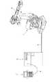
図1は、本発明の一実施形態における全体配置の概要を示している。同図において、符号1はロボット(機構部全体)を表わしており、ケーブル4を介して接続されたロボットコントローラ5によってその動作が制御される。また、ロボットコントローラ5にはケーブル6を介して教示操作盤7が接続され、教示操作盤7を操作することでロボット1の教示、手動操作等を行えるようになっている。これら基本的な構成と機能は、特に従来のロボットシシステムと変わるところはない。 FIG. 1 shows an overview of the overall arrangement in an embodiment of the present invention. In the figure, reference numeral 1 denotes a robot (entire mechanism unit), and its operation is controlled by a
本実施形態の構成が従来と異なっているのは、ロボット1のロボットアームの適所を搭載部2とし、そこに表示装置3が搭載されていることである。この表示装置3としては、有機EL表示素子を利用した表示部を持つものを採用する。有機EL表示素子は板状の柔軟な表示部(可撓性を有する表示部)を構成できるデバイスであり、ロボットアームの持つ多様な表面形状(平面、凸面、凹面など)への適合性に優れている。即ち、実質的に曲げを許さない(可撓性が無い)高剛性の表示部では搭載し難いような箇所にでも搭載が容易である(例は後述する)。 The configuration of the present embodiment is different from the conventional configuration in that an appropriate position of the robot arm of the robot 1 is used as the
表示装置3の搭載の態様については、電力供給及び信号授受の方式及び表示装置、特に表示部の固定乃至支持の方式に関連して、いくつかのバリエーションがとり得る。先ず、電力供給及び信号授受をロボット1に設けたコネクタを介して行なう一方、表示部を搭載部(ロボットアームの表面)に貼り付けて固定する方式が採用可能である。図2は(a)、(b)その例を示すもので、(a)は接続前の状態を見取図で表わし、(b)は接続後の状態を部分拡大断面図で表わしている。 Regarding the manner of mounting the
図示されているように、表示装置3は有機EL表示素子を用いた柔軟な表示部31と、表示装置3の各部を制御する制御部32と、プラグ33で構成されている。図2(b)に示したように、表示部31の背面側には貼付部36が設けられ、平面あるいは曲面への貼り付けに用いられる。貼付部36は、搭載部2の表面12の材質に合わせて、例えば粘着層、磁性層(例;磁性粉を混入したペイント層)とする。また、搭載部2の表面12への貼り付き力は、表示部31の脱落を起こさず、且つ、人手で容易に剥せる程度とすることが好ましい。 As illustrated, the
ここで注目すべきことは、表示部31が柔軟であるために、このような貼付による固定が、表面12の形状が曲面であっても無理なく行えるということである。図2(b)の例で言えば、表示部31を軽く凸状の曲面をなす表面12に押しつけるだけで、表示部31を安定させることができる。表面12が、凹状の曲面であっても同様である。もしも表示部31が柔軟でないものであったとしたら、このような貼り付けによる曲面への固定は困難である。 What should be noted here is that since the
さて、プラグ33の先端には所要数の接続ピン34、35(図2(b)ではその内の2個を例示)が設けられている。一方、ロボットアームの適所(搭載部2)には、プラグ33を受け入れる開口を有するコネクタ11が用意されている。開口の底部には、各接続ピン34、35等に対応して電力線または信号線44、45等につながるコネクタ接点が設けられている。 The
配線40は、ロボット1の各軸駆動サーボモータやエンコーダのための電力線、信号線等を含む多数の電力線と信号線を含むもので、各コネクタ接点は配線40のいくつかの分岐線のターミナルとなっている。コネクタ11の諸接点には、電力供給のためのものと信号授受のためのものが含まれ、いずれも配線40を介して、前者はロボットコントローラ5内の電源部(図示省略)へ接続され、後者はCPUのバスラインにつながる入出力インターフェイスに接続されている。表示装置3のオン/オフ操作は、例えばプラグ33のコネクタ11への脱着で行なうことができる。あるいは、教示操作盤7からオン/オフ指令をロボットコントローラ5に送り、それによって表示装置3への給電の開始/終了を制御しても良い。 The
表示装置3の制御部32自体の構成と機能については一般的なものであり、詳細な説明は省略するが、有機EL表示素子を制御するための表示駆動部、表示内容に関連するデータの授受をロボットコントローラ5との間で行なうための通信機能部などが内蔵されている。表示部32への表示内容は例えば定期点検の手順を説明する文章やイラストレーションであり、これら表示内容のデータはロボットコントローラ5内の不揮発性メモリに予め格納しておくことができる。作業者は、例えば定期点検開始にあたって次の操作を行なう。 The configuration and function of the
(1)表示装置3のプラグ33をコネクタ11に差し込む(矢印A参照)。
(2)表示部32を表面12に軽く押し付け、貼付・固定する。
(3)教示操作盤7から指令を送り、最初に表示したい情報を表示部31上に表示させる。
(4)表示画面を参照しながら、点検作業を進める。
(5)もし、別の情報を表示部31上に表示させる必要が生じたら、教示操作盤7から画面変更の指令を送り、新たに表示したい情報を表示部31上に表示させる。
(6)以後、必要に応じて(4)、(5)を繰り返し、作業が終了したら、表示部32を表面12から引き剥し、プラグ33をコネクタ11から引き抜く。(1) Insert the
(2) Lightly press the
(3) A command is sent from the teaching operation panel 7 and information to be displayed first is displayed on the
(4) Advance the inspection work while referring to the display screen.
(5) If another information needs to be displayed on the
(6) Thereafter, (4) and (5) are repeated as necessary, and when the operation is completed, the
なお、制御部32に余裕があれば、画面の頁送りボタン、頁戻しボタン等を設け、表示装置3を直接操作して、表示内容を選べるようにしても良い。更には、制御部32内に表示内容を記憶できるメモリを設けたり、表示内容を書き込んだROM(例えば定期点検用のデータを書き込んだROM)を装填できるようにしても良い。 If the
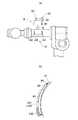
以上説明した実施形態では、電力供給及び信号授受をロボットに設けたコネクタを介して行なう一方、表示部をロボットアームの表面に貼り付けて固定する方式を採用したが、電力供給についてはバッテリを表示装置の制御部に装備することで代替が可能である。また、信号授受については、無線送受信装置を表示装置の制御部とロボットコントローラに装備することで代替が可能である。そして、表示部の固定については、表示部を受容して保持する保持部を設けることで代替が可能である。図3(a)、(b)は、これら代替手段を組み合わせた変形実施形態について説明する図で、(a)は表示装置保持前の状態を見取図で表わし、(b)は保持後の状態を部分拡大断面図で表わしている。 In the above-described embodiment, the power supply and signal exchange are performed through the connector provided on the robot, while the display unit is attached to the surface of the robot arm and fixed, but the battery is displayed for power supply. It can be replaced by installing in the control unit of the device. In addition, signal transmission / reception can be replaced by installing a wireless transmission / reception device in the control unit of the display device and the robot controller. The fixing of the display unit can be replaced by providing a holding unit that receives and holds the display unit. FIGS. 3A and 3B are diagrams for explaining a modified embodiment in which these alternative means are combined. FIG. 3A shows a state before holding the display device, and FIG. 3B shows a state after holding. It is represented by a partially enlarged sectional view.
図示されているように、表示装置8は有機EL表示素子を用いた柔軟な表示部81と、表示装置8の各部を制御する制御部82で構成されている。そして、制御部82には、表示装置3のための電力供給を行なうためのバッテリを収容するバッテリ収容部83と、無線送受信機能を持つロボットコントローラ5との間で信号授受を行なうための無線送受信部が設けられている。無線送受信部は、アンテナを収容した突起部を有し、図3(a)、(b)ではこの突起部を符号84で示した。この突起部84は把持部としても機能する。なお、無線通信のためのトランシーバ回路(図示省略)は制御部82に内蔵されている。 As illustrated, the
一方、ロボットアームの適所(搭載部)には、表示装置8の表示部81を受容して保持する保持部13が設けられている。保持部13は、例えば手紙差しのような簡単な構造を有するもので良く、ここでは前ガイド130及び左右ガイド131、132で浅い箱状の空間を作り、矢印Bで示したように、そこへ表示部81を差し込み、図3(b)に示したような状態で表示装置8を保持するものを例示した。ここで注目すべきことは、表示部81が柔軟である故に、保持部13を設ける部分のロボットアーム表面12が曲面であっても、前ガイド130、左右ガイド131、132等を同曲面に沿った形状(弓形状)にして、保持部13をコンパクトに構成できることである。もしも表示部81が柔軟でなければ、保持部13の構造を複雑になり、サイズ(厚み)も増大する。 On the other hand, a holding
表示装置8のオン/オフ操作は、例えば教示操作盤7からオン/オフ指令をロボットコントローラ5に送り、ロボットコントローラ5が無線通信で表示装置8のオン/オフすることによって行なわれる。また、有機EL表示素子を制御するための表示駆動部、表示内容に関連するデータの授受をロボットコントローラ5との間で無線通信により行なうために必要な回路が内蔵されている。既述の例と同じく、表示部81への表示内容は例えば定期点検の手順を説明する文章やイラストレーションであり、これら表示内容のデータはロボットコントローラ5内の不揮発性メモリに予め格納しておくことができる。作業者は、例えば定期点検開始にあたって次の操作を行なう。 The on / off operation of the
(1)表示装置8の突起部84を把持し、保持部13に保持させる(矢印B参照)。この時、表示部81が柔軟であるから、表示部81を保持部13に受容させる操作は円滑に行なうことができる。
(2)教示操作盤7から指令を送り、最初に表示したい情報を表示部81上に表示させる。
(3)表示画面を参照しながら、点検作業を進める。
(4)もし、別の情報を表示部81上に表示させる必要が生じたら、教示操作盤7から画面変更の指令を送り、新たに表示したい情報を表示部81上に表示させる。
(5)以後、必要に応じて(3)、(4)を繰り返し、作業が終了したら、教示操作盤7から電源オフ指令を送り、表示装置8を保持部13から取り出す。(1) The
(2) A command is sent from the teaching operation panel 7 and information to be displayed first is displayed on the
(3) Advance the inspection work while referring to the display screen.
(4) If it is necessary to display other information on the
(5) Thereafter, (3) and (4) are repeated as necessary, and when the operation is completed, a power-off command is sent from the teaching operation panel 7 and the
なお、前述の実施形態と同様、制御部82に余裕があれば、画面の頁送りボタン、頁戻しボタン、電源オン/オフボタン等を設け、表示装置8を直接操作して、電源をオン/オフし、表示内容を選べるようにしても良い。更には、制御部82内に表示内容を記憶できるメモリを設けたり、表示内容を書き込んだROM(例えば定期点検用のデータを書き込んだROM)を装填できるようにしても良い。 As in the above-described embodiment, if the
1 ロボット
2 搭載部
3、8 表示装置
4 ケーブル(ロボット−ロボットコントローラ間)
5 ロボットコントローラ
6 ケーブル(教示操作盤−ロボットコントローラ間)
7 教示操作盤
11 コネクタ
12 ロボットアーム上の搭載部の表面
13 保持部
31、81 表示部(有機EL表示素子)
32、82 表示装置の制御部
33 プラグ
34、35 接続ピン
36 貼付部(粘着層/磁性層)
40、41、44、45 配線(ロボット内)
83 バッテリ収容部
84 突起部
130 前ガイド部材
131、132 左右ガイド部材1
5 Robot controller 6 Cable (between teaching operation panel and robot controller)
7
32, 82 Control unit of
40, 41, 44, 45 Wiring (in the robot)
83
Claims (7)
Translated fromJapanese前記表示装置は、前記ロボットのロボットアーム上に貼り付けが可能な柔軟な表示部を備えていることを特徴とするロボット。A robot equipped with a display device,
The robot according to claim 1, wherein the display device includes a flexible display unit that can be attached to a robot arm of the robot.
前記表示装置は、前記ロボットのロボットアーム上に貼り付けが可能な柔軟な表示部を有するものであり、
前記搭載部に、前記表示部を受容して保持する保持部が設けられていることを特徴とするロボット。A robot having a mounting portion for mounting a display device;
The display device has a flexible display unit that can be pasted on a robot arm of the robot,
The robot according to claim 1, wherein the mounting portion is provided with a holding portion that receives and holds the display portion.
前記表示装置は、制御部と、前記ロボットのロボットアーム上に貼り付けが可能な柔軟な表示部とを有するものであり、
前記搭載部に、前記制御部との電気的接続のためのコネクタが設けられていることを特徴とするロボット。In a robot having a mounting portion for mounting a display device,
The display device includes a control unit and a flexible display unit that can be pasted on a robot arm of the robot.
A robot characterized in that a connector for electrical connection with the control unit is provided on the mounting unit.
Priority Applications (4)
| Application Number | Priority Date | Filing Date | Title |
|---|---|---|---|
| JP2004046448AJP2005231010A (en) | 2004-02-23 | 2004-02-23 | Display device |
| US11/062,467US20050187657A1 (en) | 2004-02-23 | 2005-02-22 | Robot with display device |
| EP05250982AEP1566246A1 (en) | 2004-02-23 | 2005-02-22 | Robot with flexible display screen attached on robot arm |
| CN200510008825.9ACN1660545A (en) | 2004-02-23 | 2005-02-23 | Robot with display device |
Applications Claiming Priority (1)
| Application Number | Priority Date | Filing Date | Title |
|---|---|---|---|
| JP2004046448AJP2005231010A (en) | 2004-02-23 | 2004-02-23 | Display device |
Publications (1)
| Publication Number | Publication Date |
|---|---|
| JP2005231010Atrue JP2005231010A (en) | 2005-09-02 |
Family
ID=34709179
Family Applications (1)
| Application Number | Title | Priority Date | Filing Date |
|---|---|---|---|
| JP2004046448APendingJP2005231010A (en) | 2004-02-23 | 2004-02-23 | Display device |
Country Status (4)
| Country | Link |
|---|---|
| US (1) | US20050187657A1 (en) |
| EP (1) | EP1566246A1 (en) |
| JP (1) | JP2005231010A (en) |
| CN (1) | CN1660545A (en) |
Cited By (9)
| Publication number | Priority date | Publication date | Assignee | Title |
|---|---|---|---|---|
| JP2012110995A (en)* | 2010-11-24 | 2012-06-14 | Kyokko Denki Kk | Operation teaching device which can teach operation by finger touch |
| WO2016093049A1 (en)* | 2014-12-10 | 2016-06-16 | オリンパス株式会社 | Manipulator system |
| JP2017007034A (en)* | 2015-06-22 | 2017-01-12 | ライフロボティクス株式会社 | Robot device |
| JP2017030058A (en)* | 2015-07-29 | 2017-02-09 | セイコーエプソン株式会社 | Robot, robot controller and robot system |
| CN106514713A (en)* | 2016-10-21 | 2017-03-22 | 国网山东省电力公司电力科学研究院 | Plug-and-play connector of detection device of substation patrol robot and control method |
| JP2019025623A (en)* | 2017-08-02 | 2019-02-21 | ファナック株式会社 | Robot system and robot control device |
| JP2019171528A (en)* | 2018-03-29 | 2019-10-10 | ファナック株式会社 | Robot system |
| JP2020082312A (en)* | 2018-11-29 | 2020-06-04 | ファナック株式会社 | Robot operation device |
| JP2021000724A (en)* | 2020-09-24 | 2021-01-07 | ファナック株式会社 | Robot system |
Families Citing this family (51)
| Publication number | Priority date | Publication date | Assignee | Title |
|---|---|---|---|---|
| DE112006000695T5 (en)* | 2005-03-25 | 2008-02-07 | Kabushiki Kaisha Yaskawa Denki, Kitakyushu | Automatic machine system and wireless communication method for the same |
| JP4097674B2 (en)* | 2006-02-28 | 2008-06-11 | ファナック株式会社 | Control panel with flexible display |
| EP2335337B1 (en) | 2008-10-02 | 2020-03-11 | ecoATM, LLC | Secondary market and vending system for devices |
| US11010841B2 (en) | 2008-10-02 | 2021-05-18 | Ecoatm, Llc | Kiosk for recycling electronic devices |
| US10853873B2 (en) | 2008-10-02 | 2020-12-01 | Ecoatm, Llc | Kiosks for evaluating and purchasing used electronic devices and related technology |
| US7881965B2 (en) | 2008-10-02 | 2011-02-01 | ecoATM, Inc. | Secondary market and vending system for devices |
| US9881284B2 (en) | 2008-10-02 | 2018-01-30 | ecoATM, Inc. | Mini-kiosk for recycling electronic devices |
| US20100182518A1 (en)* | 2009-01-16 | 2010-07-22 | Kirmse Noel J | System and method for a display system |
| DE202012013245U1 (en) | 2011-04-06 | 2015-09-14 | ecoATM, Inc. | Automat for recycling electronic devices |
| US9605952B2 (en) | 2012-03-08 | 2017-03-28 | Quality Manufacturing Inc. | Touch sensitive robotic gripper |
| CA2863197A1 (en)* | 2012-03-08 | 2013-09-12 | Quality Manufacturing Inc. | Touch sensitive robotic gripper |
| JP6440385B2 (en)* | 2014-06-10 | 2018-12-19 | キヤノン株式会社 | Robot arm, display device and robot system |
| US10401411B2 (en) | 2014-09-29 | 2019-09-03 | Ecoatm, Llc | Maintaining sets of cable components used for wired analysis, charging, or other interaction with portable electronic devices |
| EP4446968A3 (en) | 2014-10-02 | 2024-12-25 | ecoATM, LLC | Wireless-enabled kiosk for recycling consumer devices |
| ES2870629T3 (en) | 2014-10-02 | 2021-10-27 | Ecoatm Llc | App for device evaluation and other processes associated with device recycling |
| US10445708B2 (en) | 2014-10-03 | 2019-10-15 | Ecoatm, Llc | System for electrically testing mobile devices at a consumer-operated kiosk, and associated devices and methods |
| US11080672B2 (en) | 2014-12-12 | 2021-08-03 | Ecoatm, Llc | Systems and methods for recycling consumer electronic devices |
| US10572946B2 (en) | 2014-10-31 | 2020-02-25 | Ecoatm, Llc | Methods and systems for facilitating processes associated with insurance services and/or other services for electronic devices |
| CA3056457A1 (en) | 2014-10-31 | 2016-05-06 | Mark Vincent Bowles | Systems and methods for recycling consumer electronic devices |
| EP3215988A1 (en) | 2014-11-06 | 2017-09-13 | Ecoatm Inc. | Methods and systems for evaluating and recycling electronic devices |
| DE102015001575A1 (en) | 2015-02-07 | 2016-08-11 | Audi Ag | Method and device for visualizing the movement of a robot |
| US9358684B1 (en)* | 2015-02-18 | 2016-06-07 | Merry Electronics Co., Ltd. | Wireless transmission device and robot arm using the same |
| US10718359B2 (en) | 2015-08-21 | 2020-07-21 | Quality Manufacturing Inc. | Devices and systems for producing rotational actuation |
| EP3147752B1 (en)* | 2015-09-25 | 2018-12-26 | Technische Universität München | An arrangement for providing a user interface |
| CN205394602U (en)* | 2016-02-05 | 2016-07-27 | 深圳市大疆创新科技有限公司 | Display device , judge system and robot |
| DE102016104940A1 (en)* | 2016-03-17 | 2017-09-21 | Deutsches Zentrum für Luft- und Raumfahrt e.V. | Protective device for an effector of a manipulator, device for manipulating workpieces and method for actuating a device for manipulating workpieces |
| US10127647B2 (en) | 2016-04-15 | 2018-11-13 | Ecoatm, Llc | Methods and systems for detecting cracks in electronic devices |
| CN107303670A (en)* | 2016-04-19 | 2017-10-31 | 上海技美科技股份有限公司 | Common collaboration robot, robot system and common collaboration robot perform the control method of operation task |
| US9885672B2 (en) | 2016-06-08 | 2018-02-06 | ecoATM, Inc. | Methods and systems for detecting screen covers on electronic devices |
| CN105965481A (en)* | 2016-06-24 | 2016-09-28 | 苏州美丽澄电子技术有限公司 | Fixed home teaching robot with rotatable base |
| CN106097783A (en)* | 2016-06-24 | 2016-11-09 | 苏州美丽澄电子技术有限公司 | Private tutor robot with private tutor's teaching board |
| CN105869460A (en)* | 2016-06-24 | 2016-08-17 | 苏州美丽澄电子技术有限公司 | Family education robot |
| CN105869445A (en)* | 2016-06-24 | 2016-08-17 | 苏州美丽澄电子技术有限公司 | Tutor robot capable of automatically regulating display device |
| US10269110B2 (en) | 2016-06-28 | 2019-04-23 | Ecoatm, Llc | Methods and systems for detecting cracks in illuminated electronic device screens |
| CN106239524A (en)* | 2016-08-24 | 2016-12-21 | 珠海格力智能装备有限公司 | Robot and head assembly thereof |
| ES2760947T3 (en)* | 2017-06-23 | 2020-05-18 | Comau Spa | Functional set for an industrial machine, specifically for a robot, which includes a functional unit equipped with a safety cover |
| DE102018219268B3 (en) | 2018-11-12 | 2020-03-12 | Kuka Deutschland Gmbh | Robotic arm with a human-machine interface |
| EP3884475A1 (en) | 2018-12-19 | 2021-09-29 | ecoATM, LLC | Systems and methods for vending and/or purchasing mobile phones and other electronic devices |
| US12322259B2 (en) | 2018-12-19 | 2025-06-03 | Ecoatm, Llc | Systems and methods for vending and/or purchasing mobile phones and other electronic devices |
| EP3924918A1 (en) | 2019-02-12 | 2021-12-22 | ecoATM, LLC | Kiosk for evaluating and purchasing used electronic devices |
| KR20210125526A (en) | 2019-02-12 | 2021-10-18 | 에코에이티엠, 엘엘씨 | Connector Carrier for Electronic Device Kiosk |
| CN111738402A (en) | 2019-02-18 | 2020-10-02 | 埃科亚特姆公司 | Neural network-based physical condition assessment of electronic equipment and related systems and methods |
| WO2021127291A2 (en) | 2019-12-18 | 2021-06-24 | Ecoatm, Llc | Systems and methods for vending and/or purchasing mobile phones and other electronic devices |
| CN111360465A (en)* | 2020-04-22 | 2020-07-03 | 杭州国辰机器人科技有限公司 | Welding teaching gun based on intelligent teaching technology |
| US12271929B2 (en) | 2020-08-17 | 2025-04-08 | Ecoatm Llc | Evaluating an electronic device using a wireless charger |
| US11922467B2 (en) | 2020-08-17 | 2024-03-05 | ecoATM, Inc. | Evaluating an electronic device using optical character recognition |
| WO2022040668A1 (en) | 2020-08-17 | 2022-02-24 | Ecoatm, Llc | Evaluating an electronic device using optical character recognition |
| WO2022047473A1 (en) | 2020-08-25 | 2022-03-03 | Ecoatm, Llc | Evaluating and recycling electronic devices |
| DE102021125157A1 (en) | 2021-09-28 | 2023-03-30 | Deutsches Zentrum für Luft- und Raumfahrt e.V. | User interface device, end effector, robot and method for controlling a user interface device, an end effector and/or a robot |
| DE102023123838A1 (en)* | 2023-09-05 | 2025-03-06 | B. Braun New Ventures GmbH | Medical robot system with displayed activation button and activation procedure |
| FR3154305A1 (en)* | 2023-10-24 | 2025-04-25 | Quantum Surgical | Tool changing system for minimally invasive robotic medical interventions |
Family Cites Families (5)
| Publication number | Priority date | Publication date | Assignee | Title |
|---|---|---|---|---|
| US6131299A (en)* | 1998-07-01 | 2000-10-17 | Faro Technologies, Inc. | Display device for a coordinate measurement machine |
| JP2004503308A (en)* | 2000-06-16 | 2004-02-05 | ロボコースター・リミテッド | Vehicle equipment |
| US6645843B2 (en)* | 2001-01-19 | 2003-11-11 | The United States Of America As Represented By The Secretary Of The Navy | Pulsed laser deposition of transparent conducting thin films on flexible substrates |
| US6680724B2 (en)* | 2001-05-31 | 2004-01-20 | Hewlett-Packard Development Company, L.P. | Flexible electronic viewing device |
| JP2003080482A (en)* | 2001-09-07 | 2003-03-18 | Yaskawa Electric Corp | Robot teaching device |
- 2004
- 2004-02-23JPJP2004046448Apatent/JP2005231010A/enactivePending
- 2005
- 2005-02-22USUS11/062,467patent/US20050187657A1/ennot_activeAbandoned
- 2005-02-22EPEP05250982Apatent/EP1566246A1/ennot_activeWithdrawn
- 2005-02-23CNCN200510008825.9Apatent/CN1660545A/enactivePending
Cited By (16)
| Publication number | Priority date | Publication date | Assignee | Title |
|---|---|---|---|---|
| JP2012110995A (en)* | 2010-11-24 | 2012-06-14 | Kyokko Denki Kk | Operation teaching device which can teach operation by finger touch |
| WO2016093049A1 (en)* | 2014-12-10 | 2016-06-16 | オリンパス株式会社 | Manipulator system |
| JPWO2016093049A1 (en)* | 2014-12-10 | 2017-04-27 | オリンパス株式会社 | Manipulator system |
| JP2017007034A (en)* | 2015-06-22 | 2017-01-12 | ライフロボティクス株式会社 | Robot device |
| JP2017030058A (en)* | 2015-07-29 | 2017-02-09 | セイコーエプソン株式会社 | Robot, robot controller and robot system |
| CN106514713A (en)* | 2016-10-21 | 2017-03-22 | 国网山东省电力公司电力科学研究院 | Plug-and-play connector of detection device of substation patrol robot and control method |
| JP2019025623A (en)* | 2017-08-02 | 2019-02-21 | ファナック株式会社 | Robot system and robot control device |
| US10675767B2 (en) | 2017-08-02 | 2020-06-09 | Fanuc Corporation | Robot system and robot controller |
| US11590664B2 (en) | 2018-03-29 | 2023-02-28 | Fanuc Corporation | Robot system |
| JP2019171528A (en)* | 2018-03-29 | 2019-10-10 | ファナック株式会社 | Robot system |
| JP2020082312A (en)* | 2018-11-29 | 2020-06-04 | ファナック株式会社 | Robot operation device |
| JP2021104578A (en)* | 2018-11-29 | 2021-07-26 | ファナック株式会社 | Operating device for robot |
| US11292122B2 (en) | 2018-11-29 | 2022-04-05 | Fanuc Corporation | Robot operation apparatus |
| JP7104212B2 (en) | 2018-11-29 | 2022-07-20 | ファナック株式会社 | Operation device for robots |
| US11745333B2 (en) | 2018-11-29 | 2023-09-05 | Fanuc Corporation | Robot operation apparatus |
| JP2021000724A (en)* | 2020-09-24 | 2021-01-07 | ファナック株式会社 | Robot system |
Also Published As
| Publication number | Publication date |
|---|---|
| EP1566246A1 (en) | 2005-08-24 |
| US20050187657A1 (en) | 2005-08-25 |
| CN1660545A (en) | 2005-08-31 |
Similar Documents
| Publication | Publication Date | Title |
|---|---|---|
| JP2005231010A (en) | Display device | |
| US20080150919A1 (en) | Electronic paper display device and a system for interfacing an application | |
| US20090011793A1 (en) | Flash Memory Cell Phone With Integrated Male And Female Connectors | |
| JP2006117231A5 (en) | ||
| JP2008529108A (en) | Flash memory with integrated male and female connectors and wireless functionality | |
| US20090213332A1 (en) | Auxiliary Apparatus for Projection Apparatus and Projection System | |
| US9238363B2 (en) | Electronic component moving mechanism and printer | |
| CN108025562A (en) | Printing device | |
| TW201115257A (en) | Portable image projector and projection method | |
| JP2006004261A (en) | Portable information terminal, cradle device for portable information terminal, and information terminal system | |
| JP4576401B2 (en) | Portable printer device | |
| JP2008001256A (en) | Inside rear view mirror type drive monitoring device | |
| EP3860327B1 (en) | Tape-feeder setting work apparatus | |
| CN206686470U (en) | Remote control and electronic installation | |
| JPH11198482A (en) | Thermal printer | |
| JP2001344060A (en) | Pen for interactive board | |
| JP2009005087A (en) | Image data handling system | |
| JP2008244779A (en) | Expansion equipment | |
| CN210838280U (en) | Control device and electronic apparatus | |
| JP3110282U6 (en) | Attachment device that can be attached to and detached from the imaging lens | |
| JP2001330784A (en) | Display device for endoscope | |
| JP2002073206A (en) | Information communication system, information terminal and information terminal mounting table | |
| JP2001005595A5 (en) | Computer and computer remote control device | |
| JP2005128870A (en) | Vehicle controller | |
| KR20070071940A (en) | Removable Mobile Terminal |
Legal Events
| Date | Code | Title | Description |
|---|---|---|---|
| A977 | Report on retrieval | Free format text:JAPANESE INTERMEDIATE CODE: A971007 Effective date:20060807 | |
| A131 | Notification of reasons for refusal | Free format text:JAPANESE INTERMEDIATE CODE: A131 Effective date:20060815 | |
| A02 | Decision of refusal | Free format text:JAPANESE INTERMEDIATE CODE: A02 Effective date:20061219 |