JP2005224502A - Light irradiation apparatus - Google Patents
Light irradiation apparatusDownload PDFInfo
- Publication number
- JP2005224502A JP2005224502AJP2004038495AJP2004038495AJP2005224502AJP 2005224502 AJP2005224502 AJP 2005224502AJP 2004038495 AJP2004038495 AJP 2004038495AJP 2004038495 AJP2004038495 AJP 2004038495AJP 2005224502 AJP2005224502 AJP 2005224502A
- Authority
- JP
- Japan
- Prior art keywords
- pressure
- light irradiation
- light
- skin
- wavelength
- Prior art date
- Legal status (The legal status is an assumption and is not a legal conclusion. Google has not performed a legal analysis and makes no representation as to the accuracy of the status listed.)
- Pending
Links
- 230000000304vasodilatating effectEffects0.000claimsabstractdescription38
- 238000001816coolingMethods0.000claimsdescription24
- 238000009530blood pressure measurementMethods0.000claimsdescription13
- 239000002826coolantSubstances0.000claimsdescription11
- 238000005259measurementMethods0.000abstractdescription9
- 238000007920subcutaneous administrationMethods0.000abstractdescription9
- 230000001678irradiating effectEffects0.000abstractdescription7
- 206010033372Pain and discomfortDiseases0.000abstract1
- 238000002474experimental methodMethods0.000description19
- 210000001519tissueAnatomy0.000description19
- 230000017531blood circulationEffects0.000description18
- 210000004204blood vesselAnatomy0.000description18
- 230000008859changeEffects0.000description13
- 230000001965increasing effectEffects0.000description13
- 230000003287optical effectEffects0.000description11
- 230000006870functionEffects0.000description9
- 208000002193PainDiseases0.000description8
- 230000000694effectsEffects0.000description8
- 230000003902lesionEffects0.000description8
- 230000036407painEffects0.000description8
- 230000009471actionEffects0.000description7
- 238000001126phototherapyMethods0.000description7
- 239000000523sampleSubstances0.000description7
- 238000006243chemical reactionMethods0.000description5
- 238000010586diagramMethods0.000description5
- 230000035515penetrationEffects0.000description5
- 238000003825pressingMethods0.000description5
- 239000004065semiconductorSubstances0.000description5
- SFLSHLFXELFNJZ-QMMMGPOBSA-N(-)-norepinephrineChemical compoundNC[C@H](O)C1=CC=C(O)C(O)=C1SFLSHLFXELFNJZ-QMMMGPOBSA-N0.000description4
- MWUXSHHQAYIFBG-UHFFFAOYSA-NNitric oxideChemical compoundO=[N]MWUXSHHQAYIFBG-UHFFFAOYSA-N0.000description4
- 238000010521absorption reactionMethods0.000description4
- 239000008280bloodSubstances0.000description4
- 210000004369bloodAnatomy0.000description4
- 230000033001locomotionEffects0.000description4
- 210000003205muscleAnatomy0.000description4
- 229960002748norepinephrineDrugs0.000description4
- SFLSHLFXELFNJZ-UHFFFAOYSA-NnorepinephrineNatural productsNCC(O)C1=CC=C(O)C(O)=C1SFLSHLFXELFNJZ-UHFFFAOYSA-N0.000description4
- BVKZGUZCCUSVTD-UHFFFAOYSA-LCarbonateChemical compound[O-]C([O-])=OBVKZGUZCCUSVTD-UHFFFAOYSA-L0.000description3
- 102000001554HemoglobinsHuman genes0.000description3
- 108010054147HemoglobinsProteins0.000description3
- 241000700159RattusSpecies0.000description3
- 238000009529body temperature measurementMethods0.000description3
- BVKZGUZCCUSVTD-UHFFFAOYSA-Ncarbonic acidChemical compoundOC(O)=OBVKZGUZCCUSVTD-UHFFFAOYSA-N0.000description3
- 230000004087circulationEffects0.000description3
- 239000013078crystalSubstances0.000description3
- 201000010099diseaseDiseases0.000description3
- 208000037265diseases, disorders, signs and symptomsDiseases0.000description3
- 210000000624ear auricleAnatomy0.000description3
- 210000003195fasciaAnatomy0.000description3
- 230000006872improvementEffects0.000description3
- 230000007794irritationEffects0.000description3
- 238000000034methodMethods0.000description3
- 239000013307optical fiberSubstances0.000description3
- 238000012545processingMethods0.000description3
- 230000001225therapeutic effectEffects0.000description3
- 238000002834transmittanceMethods0.000description3
- 229940124549vasodilatorDrugs0.000description3
- 239000003071vasodilator agentSubstances0.000description3
- 206010003210ArteriosclerosisDiseases0.000description2
- 208000008035Back PainDiseases0.000description2
- CURLTUGMZLYLDI-UHFFFAOYSA-NCarbon dioxideChemical compoundO=C=OCURLTUGMZLYLDI-UHFFFAOYSA-N0.000description2
- NTYJJOPFIAHURM-UHFFFAOYSA-NHistamineChemical compoundNCCC1=CN=CN1NTYJJOPFIAHURM-UHFFFAOYSA-N0.000description2
- 208000025174PANDASDiseases0.000description2
- 208000021155Paediatric autoimmune neuropsychiatric disorders associated with streptococcal infectionDiseases0.000description2
- 240000004718PandaSpecies0.000description2
- 235000016496Panda oleosaNutrition0.000description2
- FAPWRFPIFSIZLT-UHFFFAOYSA-MSodium chlorideChemical compound[Na+].[Cl-]FAPWRFPIFSIZLT-UHFFFAOYSA-M0.000description2
- 206010052428WoundDiseases0.000description2
- 208000027418Wounds and injuryDiseases0.000description2
- NIXOWILDQLNWCW-UHFFFAOYSA-Nacrylic acid groupChemical groupC(C=C)(=O)ONIXOWILDQLNWCW-UHFFFAOYSA-N0.000description2
- 208000011775arteriosclerosis diseaseDiseases0.000description2
- 230000001427coherent effectEffects0.000description2
- 238000009429electrical wiringMethods0.000description2
- JVTAAEKCZFNVCJ-UHFFFAOYSA-Nlactic acidChemical compoundCC(O)C(O)=OJVTAAEKCZFNVCJ-UHFFFAOYSA-N0.000description2
- 230000000414obstructive effectEffects0.000description2
- WEXRUCMBJFQVBZ-UHFFFAOYSA-NpentobarbitalChemical compoundCCCC(C)C1(CC)C(=O)NC(=O)NC1=OWEXRUCMBJFQVBZ-UHFFFAOYSA-N0.000description2
- 230000008569processEffects0.000description2
- 230000002040relaxant effectEffects0.000description2
- 230000004936stimulating effectEffects0.000description2
- 210000004003subcutaneous fatAnatomy0.000description2
- 239000000126substanceSubstances0.000description2
- 230000024883vasodilationEffects0.000description2
- XLYOFNOQVPJJNP-UHFFFAOYSA-NwaterSubstancesOXLYOFNOQVPJJNP-UHFFFAOYSA-N0.000description2
- 229910018072Al 2 O 3Inorganic materials0.000description1
- 206010002091AnaesthesiaDiseases0.000description1
- 206010002383Angina PectorisDiseases0.000description1
- 101800004538BradykininProteins0.000description1
- 206010009192Circulatory collapseDiseases0.000description1
- WQZGKKKJIJFFOK-GASJEMHNSA-NGlucoseNatural productsOC[C@H]1OC(O)[C@H](O)[C@@H](O)[C@@H]1OWQZGKKKJIJFFOK-GASJEMHNSA-N0.000description1
- QXZGBUJJYSLZLT-UHFFFAOYSA-NH-Arg-Pro-Pro-Gly-Phe-Ser-Pro-Phe-Arg-OHNatural productsNC(N)=NCCCC(N)C(=O)N1CCCC1C(=O)N1C(C(=O)NCC(=O)NC(CC=2C=CC=CC=2)C(=O)NC(CO)C(=O)N2C(CCC2)C(=O)NC(CC=2C=CC=CC=2)C(=O)NC(CCCN=C(N)N)C(O)=O)CCC1QXZGBUJJYSLZLT-UHFFFAOYSA-N0.000description1
- 102100035792Kininogen-1Human genes0.000description1
- 208000008930Low Back PainDiseases0.000description1
- 241001465754MetazoaSpecies0.000description1
- 208000030858Myofascial Pain SyndromesDiseases0.000description1
- 238000007792additionMethods0.000description1
- 230000037005anaesthesiaEffects0.000description1
- 238000010171animal modelMethods0.000description1
- 210000002376aorta thoracicAnatomy0.000description1
- 206010003230arteritisDiseases0.000description1
- 210000001367arteryAnatomy0.000description1
- QVGXLLKOCUKJST-UHFFFAOYSA-Natomic oxygenChemical compound[O]QVGXLLKOCUKJST-UHFFFAOYSA-N0.000description1
- 230000005540biological transmissionEffects0.000description1
- 230000000903blocking effectEffects0.000description1
- QXZGBUJJYSLZLT-FDISYFBBSA-NbradykininChemical compoundNC(=N)NCCC[C@H](N)C(=O)N1CCC[C@H]1C(=O)N1[C@H](C(=O)NCC(=O)N[C@@H](CC=2C=CC=CC=2)C(=O)N[C@@H](CO)C(=O)N2[C@@H](CCC2)C(=O)N[C@@H](CC=2C=CC=CC=2)C(=O)N[C@@H](CCCNC(N)=N)C(O)=O)CCC1QXZGBUJJYSLZLT-FDISYFBBSA-N0.000description1
- 239000001569carbon dioxideSubstances0.000description1
- 229910002092carbon dioxideInorganic materials0.000description1
- 230000000052comparative effectEffects0.000description1
- 230000006835compressionEffects0.000description1
- 238000007906compressionMethods0.000description1
- 230000008602contractionEffects0.000description1
- 238000007796conventional methodMethods0.000description1
- 206010012601diabetes mellitusDiseases0.000description1
- 238000009792diffusion processMethods0.000description1
- 238000007599dischargingMethods0.000description1
- 239000003814drugSubstances0.000description1
- 239000007789gasSubstances0.000description1
- 230000003861general physiologyEffects0.000description1
- 239000011521glassSubstances0.000description1
- 239000008103glucoseSubstances0.000description1
- 235000015220hamburgersNutrition0.000description1
- 230000017525heat dissipationEffects0.000description1
- 229960001340histamineDrugs0.000description1
- 230000001771impaired effectEffects0.000description1
- 239000004310lactic acidSubstances0.000description1
- 235000014655lactic acidNutrition0.000description1
- 238000002647laser therapyMethods0.000description1
- 239000010410layerSubstances0.000description1
- 238000004519manufacturing processMethods0.000description1
- 239000000463materialSubstances0.000description1
- 230000007246mechanismEffects0.000description1
- 239000000203mixtureSubstances0.000description1
- 238000012986modificationMethods0.000description1
- 230000004048modificationEffects0.000description1
- 230000008345muscle blood flowEffects0.000description1
- 210000002464muscle smooth vascularAnatomy0.000description1
- 210000005036nerveAnatomy0.000description1
- 230000000399orthopedic effectEffects0.000description1
- 229910052760oxygenInorganic materials0.000description1
- 239000001301oxygenSubstances0.000description1
- 229940094443oxytocics prostaglandinsDrugs0.000description1
- 230000037368penetrate the skinEffects0.000description1
- 229960001412pentobarbitalDrugs0.000description1
- 230000003836peripheral circulationEffects0.000description1
- 230000035699permeabilityEffects0.000description1
- 229920003023plasticPolymers0.000description1
- 230000001737promoting effectEffects0.000description1
- 150000003180prostaglandinsChemical class0.000description1
- 230000009467reductionEffects0.000description1
- 230000033904relaxation of vascular smooth muscleEffects0.000description1
- 230000004044responseEffects0.000description1
- 229910052594sapphireInorganic materials0.000description1
- 239000010980sapphireSubstances0.000description1
- 206010040560shockDiseases0.000description1
- 238000003307slaughterMethods0.000description1
- 239000011780sodium chlorideSubstances0.000description1
- 239000002344surface layerSubstances0.000description1
- 238000002560therapeutic procedureMethods0.000description1
Images


Classifications
- A—HUMAN NECESSITIES
- A61—MEDICAL OR VETERINARY SCIENCE; HYGIENE
- A61B—DIAGNOSIS; SURGERY; IDENTIFICATION
- A61B18/00—Surgical instruments, devices or methods for transferring non-mechanical forms of energy to or from the body
- A61B18/18—Surgical instruments, devices or methods for transferring non-mechanical forms of energy to or from the body by applying electromagnetic radiation, e.g. microwaves
- A61B18/20—Surgical instruments, devices or methods for transferring non-mechanical forms of energy to or from the body by applying electromagnetic radiation, e.g. microwaves using laser
- A61B18/203—Surgical instruments, devices or methods for transferring non-mechanical forms of energy to or from the body by applying electromagnetic radiation, e.g. microwaves using laser applying laser energy to the outside of the body
- A—HUMAN NECESSITIES
- A61—MEDICAL OR VETERINARY SCIENCE; HYGIENE
- A61B—DIAGNOSIS; SURGERY; IDENTIFICATION
- A61B18/00—Surgical instruments, devices or methods for transferring non-mechanical forms of energy to or from the body
- A61B2018/00005—Cooling or heating of the probe or tissue immediately surrounding the probe
- A61B2018/00011—Cooling or heating of the probe or tissue immediately surrounding the probe with fluids
- A61B2018/00023—Cooling or heating of the probe or tissue immediately surrounding the probe with fluids closed, i.e. without wound contact by the fluid
- A—HUMAN NECESSITIES
- A61—MEDICAL OR VETERINARY SCIENCE; HYGIENE
- A61B—DIAGNOSIS; SURGERY; IDENTIFICATION
- A61B18/00—Surgical instruments, devices or methods for transferring non-mechanical forms of energy to or from the body
- A61B2018/00315—Surgical instruments, devices or methods for transferring non-mechanical forms of energy to or from the body for treatment of particular body parts
- A61B2018/00452—Skin
- A—HUMAN NECESSITIES
- A61—MEDICAL OR VETERINARY SCIENCE; HYGIENE
- A61B—DIAGNOSIS; SURGERY; IDENTIFICATION
- A61B90/00—Instruments, implements or accessories specially adapted for surgery or diagnosis and not covered by any of the groups A61B1/00 - A61B50/00, e.g. for luxation treatment or for protecting wound edges
- A61B90/06—Measuring instruments not otherwise provided for
- A61B2090/064—Measuring instruments not otherwise provided for for measuring force, pressure or mechanical tension
Landscapes
- Physics & Mathematics (AREA)
- Health & Medical Sciences (AREA)
- Surgery (AREA)
- Optics & Photonics (AREA)
- Life Sciences & Earth Sciences (AREA)
- Engineering & Computer Science (AREA)
- Otolaryngology (AREA)
- Nuclear Medicine, Radiotherapy & Molecular Imaging (AREA)
- Electromagnetism (AREA)
- Biomedical Technology (AREA)
- Heart & Thoracic Surgery (AREA)
- Medical Informatics (AREA)
- Molecular Biology (AREA)
- Animal Behavior & Ethology (AREA)
- General Health & Medical Sciences (AREA)
- Public Health (AREA)
- Veterinary Medicine (AREA)
- Radiation-Therapy Devices (AREA)
Abstract
Description
Translated fromJapanese本発明は、血管拡張作用を有する波長の光を生体の皮膚に照射する光照射装置に関する。 The present invention relates to a light irradiation apparatus that irradiates the skin of a living body with light having a wavelength having a vasodilating action.
従来から、ペインクリニックおよび整形外科の領域において低反応レベルレーザー治療器および直線偏光赤外線治療器などの光線療法機器が用いられている。たとえば、レーザー光を治療目的部位に照射する装置(特許文献1)、および単色光を治療目的部位に照射する装置(特許文献2)などの光線療法機器が提案されている。 Conventionally, phototherapy devices such as low response level laser therapy devices and linearly polarized infrared therapy devices have been used in the areas of pain clinics and orthopedics. For example, phototherapy devices such as a device that irradiates a treatment target site with laser light (Patent Document 1) and a device that irradiates a treatment target site with monochromatic light (Patent Document 2) have been proposed.
一般に、これらの光線療法機器は、皮膚上から光を照射することにより、「こり」および「痛み」を緩和するものである。このような光線療法機器を用いた光線治療の作用としては、一般的に神経伝達遮断作用が知られているが、さらに、近年では、循環改善による痛み関連物質(ブラジキニン、ヒスタミン、およびプロスタグランジンなど)および疲労関連物質(乳酸など)の拡散除去作用も重要視されている。特に、光の照射によって循環改善が生じる機構として、光に起因する血管平滑筋の直接的な弛緩効果が着目されている。また、光による血管平滑筋の弛緩に一酸化窒素(NO)の産生が関与していることも明らかにされてきている。 Generally, these phototherapy devices alleviate “stiffness” and “pain” by irradiating light on the skin. As an action of phototherapy using such a phototherapy device, a nerve transmission blocking action is generally known. However, in recent years, pain-related substances (bradykinin, histamine, and prostaglandins due to improvement of circulation are also known. And diffusion removal of fatigue-related substances (such as lactic acid). In particular, attention is focused on the direct relaxation effect of vascular smooth muscle caused by light as a mechanism for improving circulation by light irradiation. It has also been clarified that production of nitric oxide (NO) is involved in relaxation of vascular smooth muscle by light.
このような血管拡張による循環改善は、照射する光の波長帯に依存すると考えられている。一般の光線療法機器では、波長810〜830nmのレーザー光または波長600nm〜1600nm(ピーク波長1000nm)の直線偏光近赤外線が用いられてきた。しかしながら、いくつかの研究によれば、血管拡張による循環改善作用は、短波長側でより大きいことが報告されている。可視光領域の光による血管拡張作用の検討は不十分ではあるが、少なくとも波長300〜350nmの紫外線照射が血管を強く弛緩させることは明らかとされている(非特許文献1、非特許文献2、および非特許文献3)。 Circulation improvement by such vasodilation is considered to depend on the wavelength band of the irradiated light. In general phototherapy equipment, laser light having a wavelength of 810 to 830 nm or linearly polarized near infrared light having a wavelength of 600 nm to 1600 nm (peak wavelength of 1000 nm) has been used. However, some studies have reported that the circulatory improvement effect by vasodilation is greater on the short wavelength side. Although the examination of the vasodilatory effect by light in the visible light region is insufficient, it has been clarified that ultraviolet irradiation at least with a wavelength of 300 to 350 nm strongly relaxes the blood vessel (Non-patent
このように、血管拡張作用を有する光の照射は有望であるものの、波長帯によっては、血液中のヘモグロビンによる吸収が大きいため、組織深達性(生体組織内での光の透過性)が低いという問題がある。このような組織深達性が低い光を皮膚深部にある病巣(たとえば、筋・筋膜性の腰痛の場合、皮下脂肪組織の下にある筋膜および筋肉内の血管)まで十分に到達させようとすると、比較的高い出力エネルギーの光を照射せねばならず、皮膚表層部を損傷させてしまうおそれがある。 As described above, irradiation with light having a vasodilating action is promising, but depending on the wavelength band, absorption by hemoglobin in blood is large, so that tissue penetration (light permeability in living tissue) is low. There is a problem. Let this light with low tissue penetration reach the lesion deep in the skin (for example, in the case of myofascial low back pain, the fascia under the subcutaneous fat tissue and the blood vessels in the muscle) Then, it is necessary to irradiate light with relatively high output energy, which may damage the skin surface layer.
このように、従来の技術によれば、血管拡張作用の高い波長の光を皮膚深部の目的部位に安全かつ効率的に照射することが難しいという問題がある。また、臨床で広く使用するためには、光の照射の際に患者に苦痛や不快感を与えないことも重要である。したがって、患者に苦痛や不快感を与えることなく、血管拡張作用の高い波長の光を皮膚深部の目的部位に安全かつ効率的に照射する光照射装置が望まれている。
本発明は、以上の問題を解決するためになされたものであり、本発明の目的は、患者に苦痛や不快感を与えることなく、血管拡張作用の高い波長の光を皮下の目的部位に安全かつ効率的に照射することができる光照射装置を提供することである。 The present invention has been made to solve the above problems, and an object of the present invention is to safely apply light having a high vasodilatory effect to a subcutaneous target site without causing pain or discomfort to the patient. And it is providing the light irradiation apparatus which can irradiate efficiently.
本発明の目的は、下記する手段により達成される。 The object of the present invention is achieved by the following means.
(1)本発明の光照射装置は、生体の皮膚に当接される突出部と、前記突出部によって生体に加えられる圧力を測定する圧力測定手段と、前記突出部を進退移動させて、前記圧力測定手段で測定される圧力が予め設定された圧力範囲内となるように調整する圧力調整手段と、前記突出部によって圧力が加えられた皮膚部分に対して、血管拡張作用を有する波長の光を照射する光照射口と、を有することを特徴とする。 (1) The light irradiation device of the present invention includes a protrusion that is brought into contact with the skin of a living body, a pressure measuring unit that measures a pressure applied to the living body by the protrusion, and the protrusion is moved forward and backward. Pressure adjusting means for adjusting the pressure measured by the pressure measuring means to be within a preset pressure range, and light having a wavelength having a vasodilating action on the skin portion to which pressure is applied by the protrusion A light irradiation port for irradiating the light.
(2)上記の光照射口が前記突出部の端部に設けられている。 (2) The light irradiation port is provided at an end of the protruding portion.
(3)上記の光照射口の周辺には、皮膚を冷却するための冷却手段が設けられている。 (3) Cooling means for cooling the skin is provided around the light irradiation port.
(4)上記の冷却手段は、隙間を冷却媒体が循環するように所定の間隔を隔てて設けられた少なくとも2枚の透明体からなる二重壁構造を有する。 (4) The cooling means described above has a double wall structure made of at least two transparent bodies provided at a predetermined interval so that the cooling medium circulates in the gap.
(5)上記の冷却手段は、前記照射口の周辺に連結されたペルチェ素子を有する。 (5) The cooling means includes a Peltier element connected to the periphery of the irradiation port.
(6)上記の光照射装置は、さらに、前記突出部が進退移動可能に取り付けられている筐体と、当該筐体を保持するための保持手段と、を有し、前記保持手段は、複数のアームが関節部を介して連結した多関節アームを含んでいる。 (6) The light irradiation device further includes a housing to which the protruding portion is attached so as to be movable back and forth, and holding means for holding the housing, and the holding means includes a plurality of holding devices. The articulated arm includes an articulated arm connected through a joint.
(7)上記の圧力測定手段は、ロードセルを含んでおり、上記の圧力調整手段は、測定された圧力と設定圧力にそれぞれ対応する電圧信号間の差分をとる差動アンプと、当該差動アンプの出力に基づいて直線駆動するリニアアクチュエータとを含んでいる。 (7) The pressure measuring means includes a load cell, and the pressure adjusting means includes a differential amplifier that takes a difference between the voltage signals corresponding to the measured pressure and the set pressure, and the differential amplifier. And a linear actuator that linearly drives based on the output of.
(8)上記の圧力測定手段によって測定された圧力が予め設定された圧力範囲内にあるときにのみ、光照射されるように制御する制御手段を有する。 (8) It has a control means for controlling light irradiation only when the pressure measured by the pressure measuring means is within a preset pressure range.
(9)上記の血管拡張作用を有する波長の光は、波長が450nm〜650nmのレーザー光である。 (9) The light having a wavelength having the above vasodilatory action is laser light having a wavelength of 450 nm to 650 nm.
本発明の光照射装置によれば、突出部を進退移動させて圧力を調節しつつ、圧力が加えられた皮膚部分に対して、血管拡張作用を有する波長の光を照射するので、患者に苦痛や不快感を与えることなく、血管拡張作用の高い波長の光を皮下の目的部位に安全かつ効率的に照射することができる。 According to the light irradiation device of the present invention, the skin part to which pressure is applied is irradiated with light having a vasodilatory effect while adjusting the pressure by moving the protruding portion back and forth, so that it is painful for the patient. In addition, it is possible to safely and efficiently irradiate the subcutaneous target site with light having a high vasodilatory effect without causing discomfort.
特に、皮膚に圧力を加えて皮膚の厚さを実効的に薄くした上で、血管拡張作用を有する波長の光を照射することができるので、血管拡張作用を有する波長の光において組織深達性が低いことに起因して光を皮下にある病巣まで到達させることが難しい点を解決して、皮下の目的部位に十分な光を供給することができる。 In particular, it is possible to irradiate light with a wavelength having a vasodilating effect after effectively reducing the thickness of the skin by applying pressure to the skin. Therefore, it is possible to provide a sufficient amount of light to a target site under the skin by solving the problem that it is difficult to reach light to a lesion located under the skin due to the low level of light.
さらに、光の照射口の周辺に皮膚を冷却するための冷却手段を設けることによって、レーザー光の照射に伴う熱による皮膚表面の損傷を防止するとともに、冷却による血管拡張作用も奏することができる。 Furthermore, by providing a cooling means for cooling the skin around the light irradiation port, it is possible to prevent damage to the skin surface due to heat associated with laser light irradiation, and to exert a vasodilatory effect due to cooling.
以下、図面を参照して、本発明の実施の形態を説明する。まず、本実施の形態の光照射装置の具体的な構成を説明する前に、本実施の形態の光照射装置の前提として本発明者等によってなされた血管標本実験および血流測定実験について説明する。 Embodiments of the present invention will be described below with reference to the drawings. First, before describing the specific configuration of the light irradiation apparatus according to the present embodiment, blood vessel specimen experiments and blood flow measurement experiments performed by the present inventors as a premise of the light irradiation apparatus according to the present embodiment will be described. .
(血管標本実験)
上述したとおり、波長300〜350nmの紫外線が強い血管拡張作用を有することは知られている。しかしながら、波長300〜350nmの紫外線は、皮膚への有害な刺激作用の存在が懸念されるため、光線治療用途には不向きな面がある。したがって、ここでは、有害な刺激作用を持たない可視領域450〜650nmの波長を有するレーザー光にも十分な血管拡張作用があるか否かを以下の実験により調べた。(Blood vessel specimen experiment)
As described above, it is known that ultraviolet rays having a wavelength of 300 to 350 nm have a strong vasodilatory action. However, ultraviolet rays having a wavelength of 300 to 350 nm are unsuitable for phototherapy applications because of the concern of the presence of harmful stimulating effects on the skin. Therefore, here, whether or not laser light having a wavelength in the visible region of 450 to 650 nm having no harmful stimulating action has a sufficient vasodilating action was examined by the following experiment.
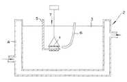
図1は、血管標本実験に用いた装置の概略構成を示す図である。 FIG. 1 is a diagram showing a schematic configuration of an apparatus used for a blood vessel specimen experiment.
まず、ラットから摘出した血管標本1を作製した。具体的には、撲殺潟血後、胸部大動脈を摘出し、血管の軸方向に対して垂直に切断することによって、長さ3mmのリング標本(径1.5mm)を作成した。 First, a
この血管標本1を、図1に示すように、容器2中のクレブス炭酸液(Krebs−bicarbonate溶液)3中にホルター5を用いて懸垂した。クレブス炭酸液3の組成は、NaCl 118mM、KCl 4.8mM、CaCl2 2.5mM、MgSO4 1.0mM、KH2PO4 1.2mM、NaHCO3 24mM、グルコース 11mMとした。また、容器2の外周に一定温度の水4を流すことによって、クレブス炭酸液3の温度が33℃となるように調整した。クレブス炭酸液3中には、95%酸素と5%二酸化炭素の混合ガスを通気させた。クレブス炭酸液3に0.03μMのノルアドレナリンを加えて、ノルアドレナリンの作用によって血管標本1を緩やかに収縮させた。ノルアドレナリンの作用による収縮が一定となった後、レーザー照射処理を開始した。As shown in FIG. 1, the
レーザー照射処理では、可視領域450〜650nmの波長を有するレーザー光として、波長532nmのレーザー光、および波長635nmのレーザー光を使用した。また、比較例として、波長810nmのレーザー光を使用した。波長532nmのレーザー光は、NdドープYVO4(Nd:YVO4)結晶を半導体レーザーで励起するタイプの固体レーザー装置(株式会社高知豊中技研製のKTGグリーンレーザー 出力を20mWまで可変可能)を用いて発生させた。波長635nmのレーザー光は、半導体レーザー装置(オーディオテクニカ社製 SU−31C 出力を30mWまで可変可能)を用いて発生させた。また、波長810nmのレーザーは、近赤外線半導体レーザー装置(歯科用の株式会社ユニタク製半導体レーザー装置 出力を100mWまで可変可能)を用いて発生させた。In the laser irradiation treatment, laser light having a wavelength of 532 nm and laser light having a wavelength of 635 nm were used as laser light having a wavelength in the visible region of 450 to 650 nm. As a comparative example, a laser beam having a wavelength of 810 nm was used. Laser light with a wavelength of 532 nm uses a solid-state laser device that excites an Nd-doped YVO4 (Nd: YVO4 ) crystal with a semiconductor laser (a KTG green laser output by Kochi Hoyonaka Giken Co., Ltd. can be varied up to 20 mW). Generated. Laser light having a wavelength of 635 nm was generated using a semiconductor laser device (SU-31C output available from Audio Technica Co., Ltd., variable up to 30 mW). The laser with a wavelength of 810 nm was generated using a near-infrared semiconductor laser device (a semiconductor laser device manufactured by Unitak Co., Ltd. for dental use whose output can be varied up to 100 mW).
なお、発生させたレーザー光は、直径1.0mmの光ファイバケーブル6によって血管標本1の近傍まで導いて照射した。光ファイバケーブル6の先端と血管標本1との間の距離は、1mmとし、各光の照射時間は、1回あたり1分間とした。光ファイバケーブル6の先端からのレーザー光の出力エネルギー(レーザー照射強度)は、レーザー照射強度測定装置(米国 COHERENT社のFieldMasterFM)を用いて測定した。 The generated laser light was guided and irradiated to the vicinity of the
血管標本1の弛緩の程度は、ノルアドレナリンの作用によって血管標本1の径方向に張力Tが加えられた状態で等寸法に保持し、光を照射する前後での張力Tの変化率(%)で評価した。すなわち、血管拡張作用が大きいほど弛緩して張力が弱くなるため、張力変化率(%)が大きくなる。 The degree of relaxation of the
表1は、血管標本実験の実験結果を示している。 Table 1 shows the experimental results of the blood vessel specimen experiment.

表1中の値は、張力変化率(%)、すなわち弛緩反応の程度を示している。なお、図中のnは実験を行ったサンプル数を意味し、張力変化率の値は、平均値±標準偏差(SD)として示した。 The values in Table 1 indicate the rate of change in tension (%), that is, the degree of relaxation reaction. In addition, n in a figure means the number of samples which experimented and the value of the tension change rate was shown as an average value +/- standard deviation (SD).
表1に示されるとおり、波長532nmのレーザー光は、出力エネルギーが1mWである場合に、約40(40.2)%の張力変化率を示し、比較的強い弛緩を発生させた。さらに、出力エネルギーが4mWである場合に、約56(56.0)%の張力変化率を示し、最大の弛緩反応を奏することがわかった。出力エネルギーが4mWの場合と出力エネルギー20mWの場合とを比較すると、出力エネルギーが4mWの場合の方が、出力エネルギーが低いにもかかわらず、むしろ強い血管拡張作用を奏する。このように、波長532nmのレーザー光を用いる場合には、出力エネルギーを比較的低くしても、強い血管拡張作用を生じさせることができることが明らかとなった。 As shown in Table 1, the laser beam having a wavelength of 532 nm exhibited a tension change rate of about 40 (40.2)% when the output energy was 1 mW, and caused relatively strong relaxation. Furthermore, it was found that when the output energy was 4 mW, the tension change rate was about 56 (56.0)%, and the maximum relaxation reaction was achieved. Comparing the case where the output energy is 4 mW and the case where the output energy is 20 mW, the case where the output energy is 4 mW exhibits rather strong vasodilatory action, although the output energy is low. Thus, it has been clarified that when a laser beam having a wavelength of 532 nm is used, a strong vasodilatory effect can be produced even if the output energy is relatively low.
また、波長635nmのレーザー光では、出力エネルギーを1mW、および4mWとした場合に、張力変化率が、約23(22.7)%、および約28(28.2)%にとどまった。しかしながら、出力エネルギーを10mWとした場合には、張力変化率は、約42(41.7)%に達し、比較的強い弛緩を発生させた。したがって、波長635nmのレーザー光は、波長532nmのレーザー光に比べて、若干、照射強度を上げなければならないものの、十分な血管拡張作用を有することが確認された。 Further, in the case of laser light having a wavelength of 635 nm, when the output energy was 1 mW and 4 mW, the tension change rate was only about 23 (22.7)% and about 28 (28.2)%. However, when the output energy was 10 mW, the rate of change in tension reached approximately 42 (41.7)%, which produced relatively strong relaxation. Therefore, it was confirmed that the laser beam having a wavelength of 635 nm has a sufficient vasodilatory effect although the irradiation intensity has to be slightly increased as compared with the laser beam having a wavelength of 532 nm.
一方、波長810nmのレーザー光では、出力エネルギーが4mW乃至10mWの範囲においては、ほとんど弛緩反応を奏することがなかった(張力変化率で4%、10.6%程度)。出力エネルギーを50mWとした場合に、張力変化率が約26(26.3)%程度となり、わずかな弛緩が認められたものの、さらに、出力エネルギーを100mWと高めても、逆に、ほとんど弛緩反応を示さなかった。 On the other hand, the laser beam having a wavelength of 810 nm hardly exhibited a relaxation reaction when the output energy was in the range of 4 mW to 10 mW (4% or 10.6% in terms of tension change rate). When the output energy is 50 mW, the rate of change in tension is about 26 (26.3)%, and a slight relaxation is observed. However, even if the output energy is increased to 100 mW, on the contrary, almost a relaxation reaction. Did not show.
レーザー光の波長は、レーザーの発光原理に起因して素子固有の離散的な値しかとれないため、波長を自由に変更して、血管拡張作用の波長依存性を検証することは難しいが、本実験によれば、波長650nm程度より短波長であれば、十分な弛緩作用、すなわち、血管拡張作用を奏することができ、波長650nm程度より長波長になると、わずかな弛緩作用しか発揮できないといえる。なお、波長が短くなると、血管拡張作用自体は徐々に高まるものの、血液中のヘモグロビンによる吸収が大きくて組織深達性があまりにも低くなるとともに、波長帯によっては皮膚への有害な刺激をおよぼすおそれがある。このため、使用する波長は、450nmより長波長であることが望ましい。したがって、結論としては、血管拡張作用を有する波長の光として、450nm乃至650nmの波長のレーザー光を用いることが望ましいといえる。 Since the wavelength of the laser beam can only be a discrete value unique to the device due to the laser emission principle, it is difficult to verify the wavelength dependence of the vasodilator action by changing the wavelength freely. According to experiments, it can be said that if the wavelength is shorter than about 650 nm, a sufficient relaxing action, that is, a vasodilating action can be achieved, and if the wavelength is longer than about 650 nm, only a slight relaxing action can be exhibited. When the wavelength is shortened, the vasodilator action itself increases gradually, but the absorption by the hemoglobin in the blood is large and the tissue depth is too low, and depending on the wavelength band, it may cause harmful irritation to the skin. There is. For this reason, it is desirable that the wavelength used be longer than 450 nm. Therefore, as a conclusion, it can be said that it is desirable to use a laser beam having a wavelength of 450 nm to 650 nm as the light having a vasodilatory effect.
また、クレブス炭酸液の温度を33℃から36℃に変えて、同様の実験を行ったところ、血管拡張作用は、36℃の場合よりも33℃の方が大きかった。したがって、血管拡張作用は、熱によって間接的に引き起こされるのではなく、特定の波長の光による直接的な弛緩効果によることが検証された。 Further, when the same experiment was conducted by changing the temperature of the Krebs carbonic acid solution from 33 ° C. to 36 ° C., the vasodilatory action was greater at 33 ° C. than at 36 ° C. Therefore, it was verified that the vasodilatory effect is not caused indirectly by heat, but by a direct relaxation effect by light of a specific wavelength.
(血流測定実験)
次に、丸ごと動物を用いて、レーザー光照射による血流量増加を測定する実験を行った。実験動物としてラットを用いた。ペントバルビタールで麻酔した後、ラットの耳介部(耳たぶ)の内側面には血流測定装置(アドバンスレーザーフローメーター)のプローブを密着させる一方、耳介部の外側面にはレーザー照射口を配置した。すなわち、血流測定装置のプローブとレーザー照射口とは、耳介部を挟んで対向する位置に配置された。血流測定装置によって測定された血流量は、ペンレコーダを用いて記録した。(Blood flow measurement experiment)
Next, using a whole animal, an experiment was conducted to measure the increase in blood flow due to laser light irradiation. Rats were used as experimental animals. After anesthesia with pentobarbital, the probe of the blood flow measurement device (advanced laser flow meter) is placed in close contact with the inner surface of the rat pinna (earlobe), while the laser irradiation port is placed on the outer surface of the pinna did. That is, the probe of the blood flow measurement device and the laser irradiation port are arranged at positions facing each other with the auricle portion interposed therebetween. The blood flow measured by the blood flow measuring device was recorded using a pen recorder.
実験には、波長が532nmのレーザー光(出力エネルギーが5mWおよび20mW)と、波長が810nmのレーザー光(出力エネルギーが20mW)を用いた。照射時間は、1分、および5分とした。 In the experiment, laser light with a wavelength of 532 nm (output energy of 5 mW and 20 mW) and laser light with a wavelength of 810 nm (output energy of 20 mW) were used. The irradiation time was 1 minute and 5 minutes.
表2に、血流測定実験の結果について示す。実験結果は、それぞれの波長のレーザー光を照射した直後の血流量の増加率(照射直前の血流量に対する照射直後の血流増加量の比率)で示している。 Table 2 shows the results of the blood flow measurement experiment. The experimental results are indicated by the rate of increase in blood flow immediately after irradiation with laser light of each wavelength (ratio of the increase in blood flow immediately after irradiation to the blood flow immediately before irradiation).
表2に示されるとおり、波長532nmで出力エネルギー5mWのレーザー光照射の場合、および波長810nmで出力エネルギー20mWのレーザー光照射の場合は、ほとんど血流に影響を及ぼさなかった。一方、波長532nmで出力エネルギー20mWのレーザー光照射の場合には、血流量が増大した。特に、照射時間が1分から5分へと長くなるにしたがって血流量が増加することがわかった。 As shown in Table 2, in the case of laser light irradiation with a wavelength of 532 nm and an output energy of 5 mW, and the case of laser light irradiation with a wavelength of 810 nm and an output energy of 20 mW, the blood flow was hardly affected. On the other hand, in the case of laser light irradiation with a wavelength of 532 nm and an output energy of 20 mW, the blood flow increased. In particular, it was found that the blood flow increased as the irradiation time increased from 1 minute to 5 minutes.
また、温度の影響を検討するために、血流測定装置のプローブの代わりに温度測定プローブを耳介の内側面に装着して、各波長のレーザー光を1分、5分、および10分にわたって照射した場合の耳介部の温度について測定した。実験では、波長532nmで出力エネルギー20mWのレーザー光を照射した場合と、波長810nmで出力エネルギー20mWのレーザー光を照射した場合とを比較した。 In addition, in order to examine the influence of temperature, a temperature measurement probe is attached to the inner surface of the auricle instead of the probe of the blood flow measurement device, and laser light of each wavelength is applied for 1 minute, 5 minutes, and 10 minutes. The temperature of the auricle portion when irradiated was measured. In the experiment, a case where a laser beam with an output energy of 20 mW was irradiated at a wavelength of 532 nm was compared with a case where a laser beam with an output energy of 20 mW was irradiated at a wavelength of 810 nm.
レーザー光の照射による温度変化の測定結果を表3に示す。 Table 3 shows the measurement results of temperature changes due to laser light irradiation.
表3に示されるとおり、波長532nmの場合と波長810nmの場合とで温度変化に差異はみられなかった。具体的には、波長532nmの場合および波長810nmの場合の双方とも、レーザー光の照射によって、1〜2℃程度の温度上昇が観察された。 As shown in Table 3, there was no difference in temperature change between the wavelength of 532 nm and the wavelength of 810 nm. Specifically, in both cases of the wavelength of 532 nm and the wavelength of 810 nm, a temperature increase of about 1 to 2 ° C. was observed by laser light irradiation.
このように波長532nmの場合と波長810nmの場合とで温度変化に差異がないにもかかわらず、表2に示されるような血流量の増加に差異が生じることから、表2に示されるようなレーザー照射による血流増加作用は、熱によって間接的に引き起こされるのではなく、特定の波長の光による直接的な弛緩効果によることが本実験によっても検証された。 Thus, although there is no difference in temperature change between the case of wavelength 532 nm and the case of wavelength 810 nm, there is a difference in the increase in blood flow as shown in Table 2. It was also verified in this experiment that the blood flow increasing effect by laser irradiation is not caused indirectly by heat, but by a direct relaxation effect by light of a specific wavelength.
以上、波長532nmおよび波長635nmの光を例として説明したように、可視光領域(波長450nm〜630nm)の光は、比較的低いエネルギーで血管を強く拡張する作用を有する。したがって、皮下深部の皮膚と筋肉との境界にある筋膜まで有効量の光を到達させることさえできれば、治療効果を期待できる。具体的には、筋・筋膜性の腰痛や肩こりなどのように、筋膜または筋肉の血流が障害されて起こる疾患を緩和することができる。 As described above, light having a wavelength of 532 nm and a wavelength of 635 nm is described as an example. Light in the visible light region (wavelength 450 nm to 630 nm) has a function of strongly expanding a blood vessel with relatively low energy. Therefore, a therapeutic effect can be expected as long as an effective amount of light can reach the fascia at the boundary between the skin and muscle in the deep skin. Specifically, it is possible to relieve diseases caused by impaired fascia or muscle blood flow, such as muscle / fascial back pain and stiff shoulders.
本発明は、このように血管拡張作用を有する波長の光、好ましくは、波長が450nm〜650nmのレーザー光を生体の皮膚へ照射するものである。以下、本発明の実施の形態を説明する。 The present invention irradiates the skin of a living body with light having a wavelength having a vasodilating action, preferably laser light with a wavelength of 450 nm to 650 nm. Embodiments of the present invention will be described below.
(第1の実施の形態)
本実施の形態の光照射装置は、血管拡張作用を有する波長の光の組織深達性が低いことに起因して光を皮膚深部にある病巣まで到達させることが難しい点を解決するものである。特に、本実施の形態の光照射装置は、患者に苦痛や不快感を与えないように自動的に圧力を調整して、突出部で皮膚を加圧しつつ、この加圧された皮膚部分に対して血管拡張作用を有する波長の光を照射するものである。本実施の形態の光照射装置は、皮膚に局所的な圧力を加えて皮膚部分の厚みを実効的に薄くすることによって、光の照射エネルギーを高めることなく、皮膚深部にある病巣まで有効量の光を届くように構成されている。(First embodiment)
The light irradiation apparatus according to the present embodiment solves the problem that it is difficult to make light reach a lesion in the deep part of the skin due to low tissue penetration of light having a wavelength having a vasodilatory effect. . In particular, the light irradiation apparatus of the present embodiment automatically adjusts the pressure so as not to cause pain or discomfort to the patient, pressurizes the skin with the protruding portion, and applies to the pressurized skin portion. Thus, light having a wavelength having a vasodilating action is irradiated. The light irradiation apparatus of the present embodiment effectively reduces the thickness of the skin portion by applying local pressure to the skin, thereby increasing the effective amount up to the lesion deep in the skin without increasing the light irradiation energy. It is configured to receive light.
図2は、本発明の一実施の形態における光照射装置の全体構成を示す図である。図2に示されるとおり、光照射装置10は、光照射部100と、制御部200と、多関節アーム300とを有している。 FIG. 2 is a diagram showing an overall configuration of a light irradiation apparatus according to an embodiment of the present invention. As illustrated in FIG. 2, the
光照射部100は、筐体102内に進退移動可能に設けられた突出部104を有している。突出部104は、皮膚に対して圧力を加えて皮膚の厚さを実効的に薄くするために生体の皮膚上に当接される部分である。突出部104の先端には、光を照射するための光照射口が設けられている。 The
制御部200は、光照射装置10の制御を行うものである。具体的には、制御部200は、突出部104によって皮膚に加えられる圧力を調整するために、突出部104を進退移動させるように制御する。また、制御部200には、圧力条件や照射条件を設定するための操作部202と、種々の表示を行う表示パネル204とが設けられている。 The
多関節アーム300は、複数のアーム301、302が関節部303を介して回動自在に取り付けられたものである。多関節アーム300は、光照射部100を患者の皮膚上の各点に移動し、その点上で保持するために役立つ。多関節アーム300の一端は、光照射部の筐体102に取り付けられており、その他端は、制御部200のスタンド206に取り付けられている。多関節アーム300とスタンド206は、光照射部100の筐体102を保持する保持手段として機能する。なお、多関節アーム300の内部には、光照射部100と制御部200との間を電気的に接続するための電気配線(不図示)が設けられており、この電気配線を通じて、光照射部100と制御部200との間で電気信号がやり取りされる。 The
次に、光照射部100の内部の構成を説明する。図3は、光照射部100内部の構成を模式的に示す図である。光照射部100は、筐体102と、筐体102の内部に移動可能に保持された突出部104と、突出部104に作用する圧力を測定する圧力測定部106と、突出部104を軸線に沿って進退移動させる駆動部108とが設けられている。 Next, the internal configuration of the
また、筐体102の内部には、光学部品が配置されている。光学部品は、血管拡張作用を有する波長帯のレーザー光を放出するレーザー発光素子110と、レーザー発光素子から放出されたレーザー光のビーム径を拡大する拡大手段であるビームエクスパンダー112と、ビームエクスパンダー112によってビーム径が拡大されたレーザー光を生体の皮下に焦点を結ぶように絞り込むための集光手段である凸レンズ114とを含む。 An optical component is disposed inside the
このうち凸レンズ114は、突出部104の端部に設けられており、血管拡張作用を有する波長の光を照射する光照射口として機能する。凸レンズ114は、この突出部104の端部が生体の皮膚20に当接した状態でレーザー光を生体の皮下に焦点を結ぶように絞り込むものである。レーザー発光素子110としては、上述した血管標本実験で説明したように、半導体レーザー素子およびNdドープYVO4結晶などの固体レーザー素子を用いることができる。Among these, the
また、突出部104は、光照射口である凸レンズ114を覆うように設けられた二重壁構造120を冷却手段として有していることが望ましい。二重壁構造120は、隙間を冷却媒体が循環するように所定の間隔を隔てて設けられて少なくとも2枚の透明体121a,121bを有する。また、二重壁構造120は、この隙間に冷却媒体を供給するための供給口122と、この隙間から冷却媒体を排出するための排出口123とを有する。本実施の形態では、冷却媒体は、水であるが、透明であるかぎり他の冷却媒体を用いることもできる。このように、二重壁構造120およびその隙間を循環する冷却媒体がともに透明であるため、光照射口である凸レンズ114から照射された光が遮られることが防止される。 Further, it is desirable that the
冷却媒体の温度は、0乃至30℃とすることが望ましい。皮膚20の温度を測定する温度測定手段である温度センサ109による温度測定結果に応じて冷却媒体の温度を調節して、皮膚20の温度を制御することができる。この結果、レーザー光の照射による皮膚20の温度上昇分を冷却により補償することができ、皮膚20に与える影響を抑制することができる。したがって、二重壁構造120を有する突出部104は、皮膚20に圧力を加える加圧機能とともに、皮膚20を冷却する冷却機能を有することとなる。 The temperature of the cooling medium is preferably 0 to 30 ° C. The temperature of the
なお、突出部104の内部は、レーザー発光素子110からビームエクスパンダー112を経て光照射口である凸レンズ114に至る光路(図中に点線で表示)を遮らないように中空構造となっている
光照射口である凸レンズ114から照射される光の波長は、好ましくは、波長450〜650nmである。これは、上述した血管標本実験からわかるように、波長650nmより長くなると、十分な血管拡張作用が得られないおそれがある一方、波長が450nmより短くなると、血液中のヘモグロビンによる吸収が大きくて組織深達性が低くなりすぎるとともに波長帯によっては皮膚20への有害な刺激をおよぼすおそれがあるためである。The
また、光照射口から照射される光の出力エネルギーは、5mW〜20Wであることが好ましい。これは、出力エネルギーが5mW以下であると、レーザーエネルギー自体があまりにも弱いので、レーザー光が皮膚組織を透過して皮下深部まで到達することができず、皮下深部における十分な治療効果が期待できないためである。一方、出力エネルギーを20W以下とすることが望ましいのは、20Wを越えると、光照射口の近傍を二重壁構造120を用いて冷却しても、皮膚組織への影響が心配されるためである。また、皮下深部においてレーザー光が焦点を結ぶことによって最もエネルギーが高くなる部分でのエネルギーが、50mW以下となるようにすることが望ましい。 Moreover, it is preferable that the output energy of the light irradiated from a light irradiation opening is 5 mW-20W. This is because if the output energy is 5 mW or less, the laser energy itself is too weak, so that the laser light cannot penetrate the skin tissue to reach the subcutaneous depth, and a sufficient therapeutic effect in the subcutaneous depth cannot be expected. Because. On the other hand, it is desirable to set the output energy to 20 W or less because if it exceeds 20 W, there is a concern about the influence on the skin tissue even if the vicinity of the light irradiation opening is cooled using the
筐体102内に設けられる圧力測定部106は、突出部104に作用する圧力(すなわち突出部104によって皮膚20に加えられる圧力に相当)を測定する圧力センサとして機能するロードセルを収容している。このロードセルには、突出部104の基部が接続されている。ここで、突出部104の基部とロードセルとは、種々の方法で接続することが可能である。たとえば、突出部104が皮膚20に当接されて圧力を受けた際に軸線に沿って内方へ微動してロードセルに力を伝達できるように突出部104を取り付けることができる。なお、ロードセルの構造は、従来のものと同様であるので詳しい説明を省略する。本実施の形態では、ロードセルなどの圧力測定部106は、レーザー発光素子110からビームエクスパンダー112を経て光照射口である凸レンズ114に至る光路を遮らないように、配置される必要がある。 The
駆動部108は、突出部104を軸線に沿って進退移動させるリニアアクチュエータである。リニアアクチュエータとしては、たとえば、中空軸モータ108aとボールネジ108bとを組み合わせて直線運動を得るタイプの構成を採用することができる。この場合、筐体102内に固定された中空軸モータ108bのロータ部分に設けられたボールナットと突出部104の基部側から伸延されたボールネジ108bとが螺合される。また、突出部104が回転しないようにリニアスライダ等(不図示)が設けられる。このように構成することによって、ロータが正方向に回転すると突出部104が軸に沿って外方に移動し、ロータが負方向に回転すると突出部104が軸に沿って内方に移動することとなる。 The
しかしながら、駆動部108の構成としては、この場合に限られず、ワイヤ、プーリ、ベルトを用いて直線運動を得るタイプ、ギア変換タイプ、およびリニアモータタイプなど種々のリニアアクチュエータを採用することができる。リニアアクチュエータの具体的な内部構成については、詳しい説明を省略する。 However, the configuration of the
なお、駆動部108は、レーザー発光素子110からビームエクスパンダー112を経て光照射口である凸レンズ114に至る光路を遮らないように配置される必要がある。たとえば、駆動部108として、中空軸モータ108aとボールネジ108bとを組み合わせて直線運動を得る構成を採用した場合には、突出部104の基部側から伸延されるボールネジ108bにおいて軸線にそって貫通孔を形成することができる。この場合、この貫通孔を通じてレーザー光を通過させることができる。 The
次に、圧力測定部106によって測定された圧力に応じて駆動部108を駆動して圧力を調整するための回路構成例について説明する。図4は、本実施の形態の光照射装置の回路構成例を模式的に示す図である。なお、図4に示される回路構成は、主として、上記の制御部200に実装されるが、その一部は光照射部100に実装されてもよい。 Next, an example of a circuit configuration for adjusting the pressure by driving the
図4に示される回路構成例では、制御部200は、フィードバック制御回路を構成しており、アンプ210、実測圧表示回路220、圧設定回路230、設定圧表示回路240、差動アンプ250、およびモータ駆動回路260を有する。なお、ここでは、圧力測定部106としてロードセル116を含み、駆動部108としてモータ108aを含む場合を例にとって説明する。 In the circuit configuration example shown in FIG. 4, the
アンプ210は、ロードセル116からの電圧信号を検出する。なお、ロードセル116は、ホイーストンブリッジ回路(不図示)を内蔵しており、このホイーストンブリッジ回路の出力が電圧信号として検出される。得られた電圧信号は、実測圧力に対応するものであり、この電圧信号が実測圧表示回路220へ入力されるとともに、差動アンプ250にも入力される。実測圧表示回路220は、実測圧力値を表示パネル204に表示する。 The
圧設定回路230は、目標とする圧力を設定するための回路である。設定される圧力(「設定圧力」と称する)は、取扱者(施術者)が操作部202を操作することによって適宜に変更することができる。設定圧力に対応する電圧信号は、設定圧表示回路240へ入力されるとともに、差動アンプ250にも入力される。設定圧表示回路240は、設定圧力値を表示パネル204に表示する。 The
差動アンプ250は、実測圧力と設定圧力にそれぞれ対応する電圧信号間の差分をとるものであり、必要に応じて所定の利得で増幅してモータ駆動回路260に伝える。この結果、モータ駆動回路260は、実測圧力と設定圧力の差分に応じてモータ108aに指令を出力する。指令を受けたモータ108aが回転すると、それに応じて突出部104が進退移動する。 The
このような回路によれば、突出部104を皮膚20に当接した場合に、突出部104を進退移動させて、圧力測定部106によって測定された圧力が設定圧力と同じになるように調整することができる。 According to such a circuit, when the
以上のように構成される本実施の形態の光照射装置10は、以下のように処理を行う。 The
まず、突出部104によって皮膚20に加える圧力条件が設定される。設定圧力の値は、適宜に定めることができる。 First, the pressure condition applied to the
次に、多関節アームが操作されて、光照射部100の突出部104が皮膚20に押し付けられる。突出部104が皮膚20に押し付けられた後、圧力測定部106は、突出部104によって生体に加えられる圧力を測定する。なお、圧力の測定は、取扱者がスイッチなどを操作することによって開始されてもよく、あるいは、突出部104が皮膚20に当接されたことによる圧力変化を圧力測定部106によって検知することによって自動的に開始されてもよい。 Next, the articulated arm is operated, and the
そして、実測圧力Pが設定圧力と同じであるか否かが判断される。設定圧力は、一つの圧力値として設定されてもよいが、誤差や制御の安定性を考慮して、ある程度の幅を持った設定圧力範囲を設定圧力としてもよい。実測圧力Pが設定圧力と同じでない場合には、圧力調整処理がなされる。まず、差動アンプ250によって、実測圧力Pと設定圧力にそれぞれ対応する電圧信号間の差分が出力されて、この出力に応じて、リニアアクチュエータである駆動部108が直線駆動される。この結果、突出部104が軸線に沿って移動して圧力が調整される。すなわち、差動アンプ250と駆動部108とは、実測圧力Pが設定圧力と同じになるように調整する圧力調整手段として機能する。 Then, it is determined whether or not the actually measured pressure P is the same as the set pressure. The set pressure may be set as a single pressure value, but a set pressure range having a certain range may be set as the set pressure in consideration of error and control stability. If the measured pressure P is not the same as the set pressure, a pressure adjustment process is performed. First, the
具体的には、実測圧力Pが設定圧力より小さい場合には、突出部104が外方(突き出し方向)へ移動する。この結果、圧力が強められる。一方、実測圧力Pが設定圧力より大きい場合には、突出部104が内方(引き戻し方向)へ移動する。この結果、圧力が弱められる。なお、これらの圧力の測定処理、設定圧力との比較処理、および圧力調整処理は、繰り返し実行されている。この結果、患者の身体が動いた場合には、それに応じて突出部104が内方または外方に移動する。したがって、常に、実測圧力が設定圧力と一致するように加圧強度が制御されることとなる。 Specifically, when the actually measured pressure P is smaller than the set pressure, the protruding
そして、実測圧力と設定圧力とが一致するのをまって、圧力が加えられた皮膚部分に対して、血管拡張作用を有する波長のレーザー光が照射される。すなわち、制御部200は、圧力測定部106によって測定された圧力が予め設定された圧力範囲内にあるときのみ、光照射されるように制御する。このように圧力を加えて皮膚部分の厚みを実効的に薄くすることによって、光の照射エネルギーを高めることなく、皮膚深部にある病巣まで有効量の光を届かせることができる。 Then, the measured pressure and the set pressure coincide with each other, and the skin portion to which the pressure is applied is irradiated with laser light having a wavelength having a vasodilating action. That is, the
ここで、皮膚20に圧力を加えつつ光を照射することの有効性を示すために、豚の皮膚組織を用いた加圧実験の結果を示す。ブタの皮下脂肪付きの皮膚組織(厚み10mm)を採取し、この皮膚組織を2枚のアクリル板に挟み込んで加圧した。そして、加圧した状態で皮膚組織に対して、波長532nmのレーザー光を照射し、皮膚組織を透過するレーザー照射強度をレーザー照射強度測定装置(米国 COHERENT社のFieldMasterFM)を用いて測定して、レーザー光の透過率を測定した。 Here, in order to show the effectiveness of irradiating light while applying pressure to the
この結果、皮膚組織の厚さを8mm、および6mmになるように加圧したときの透過率は、それぞれ、加圧していない場合(皮膚組織の厚さ10mm)の透過率の1.3倍、および1.4倍となった。この実験では、皮膚組織を2枚のアクリル板で挟み込むことによって圧力を加えたが、本実施の形態の構成においても、突出部104によって皮膚20に圧力を加えることによって、皮膚組織の厚みが実効的に薄くなる効果が期待できる。したがって、光の照射エネルギーを高めることなく、皮膚深部にある病巣まで有効量の光を届かせることができる。また、光の照射エネルギーを低くできるために、皮膚温度の調節も容易となる。 As a result, the transmittance when the thickness of the skin tissue is pressurized to 8 mm and 6 mm is 1.3 times the transmittance when the pressure is not applied (the thickness of the skin tissue is 10 mm), And 1.4 times. In this experiment, the pressure was applied by sandwiching the skin tissue between two acrylic plates. However, even in the configuration of the present embodiment, the thickness of the skin tissue is effectively increased by applying the pressure to the
なお、本実施の形態の光照射装置10は、皮下深部の病巣を目的部位とする場合に好適に用いられるが、比較的表層の抹消循環不全にも効果が期待できる。具体的には、皮下に存在する、筋・筋膜性の腰痛、肩こり、狭心症、裾創、閉塞性動脈硬化症(ASO)、閉塞性動脈炎(バージャー病TAO)、および糖尿病性動脈閉塞などの循環不全を伴う幅広い疾患に対して有用である。さらに、血流の改善により治療効果が期待でき、手術層の創傷治療の促進にも有用である。 The
以上のように、本実施の形態の光照射装置10は、以下のような効果を奏する。 As described above, the
(ア)患者に苦痛や不快感を与えることなく、血管拡張作用の高い波長の光を皮膚深部の目的部位に安全かつ効率的に照射することができる。 (A) It is possible to safely and efficiently irradiate the target site in the deep part of the skin with light having a high vasodilatory effect without causing pain or discomfort to the patient.
(イ)特に、常に設定範囲の圧力で患者の皮膚20を押し付けることが可能となるので、加える圧力が高すぎることによって患者に苦痛を与えることを防止しつつ、圧力が弱すぎることによる効果の低減を防止することができる。 (B) In particular, the patient's
(ウ)特に、波長450〜650nmのレーザー光を照射するので、十分な血管拡張作用を得ることができるとともに、組織深達性が低くなりすぎたり、皮膚20への有害な刺激をおよぼしたりすることが防止される。 (C) Particularly, since laser light with a wavelength of 450 to 650 nm is irradiated, a sufficient vasodilatory effect can be obtained, tissue deepness becomes too low, and harmful irritation to the
(エ)また、本実施の形態の光照射装置10は、光照射部1の照射口を皮膚20に押し付けることによって、実測圧力が所定の設定圧力範囲となった場合に限って、レーザー照射されるように構成されているので、本装置の取扱者および患者がレーザー光を直視することが防止でき、この点においても安全性を高めることができる。 (D) Moreover, the
(オ)患者が動いた場合などであっても、その動きに合わせて突出部104が移動するので、操作が容易となる。 (E) Even when the patient moves, the
(カ)突出部104の端部に照射口となる凸レンズ114が設けられており、この照射口を通じて光を照射することができるので、圧迫照射が容易である。 (F) A
(キ)光照射部100の筐体102は、多関節アーム300およびスタンド206からなる保持手段によって保持されるので、光照射部100を皮膚20上の各点に移動することができるとともに、光照射部100を各点上で保持することができる。したがって、操作性が高まる。 (G) Since the
(ク)ロードセルを用いた圧力測定部106を筐体102内に組み込んだので、リミットスイッチなどを用いる場合と比べて、高精度かつ連続的に圧力を実測することができる。また、装置を小型化することができる。 (C) Since the
(ケ)測定された圧力と設定された設定圧力との間の差分を増幅する差動アンプを用いて、差動アンプの出力に基づいてリニアアクチュエータが直線駆動されるので、リミットスイッチなどを用いる場合と異なり、患者間の状態の違いや個人差に柔軟に対応して設定値を変化させることもでき、適切に選択された一定圧力を加えることができる。 (G) Since the linear actuator is linearly driven based on the output of the differential amplifier using a differential amplifier that amplifies the difference between the measured pressure and the set set pressure, a limit switch or the like is used. Unlike the case, the set value can be changed in a flexible manner corresponding to the difference in state between patients and individual differences, and an appropriately selected constant pressure can be applied.
(コ)突出部104の外面には、光照射口である凸レンズ114を覆うように、冷却手段として二重壁構造120が設けられているので、皮膚20の温度に応じて、二重壁構造120の隙間に供給する冷却媒体の温度を調節することによって、皮膚温度を適切な温度に保つことができる。 (E) Since the
(第2の実施の形態)
第1の実施の形態では、冷却手段として、二重壁構造を設けた場合を説明したが、本実施の形態では、冷却手段として、ペルチェ素子を設ける。他の構成は、第1の実施の形態と同様であるので、詳しい説明は、省略する。なお、第1の実施の形態と同様の部材には、同じ符号を用いて説明する。(Second Embodiment)
In the first embodiment, the case where the double wall structure is provided as the cooling means has been described. However, in this embodiment, a Peltier element is provided as the cooling means. Since other configurations are the same as those of the first embodiment, detailed description thereof is omitted. In addition, the same code | symbol is demonstrated to the member similar to 1st Embodiment.
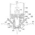
図5は、本実施の形態の光照射装置10における光照射部100内部の構成を模式的に示す図である。光照射部100は、筐体102と、筐体102の内部に移動可能に保持された突出部104と、突出部104に作用する圧力を測定する圧力測定部106と、突出部104を軸線に沿って進退移動させる駆動部108とが設けられている。 FIG. 5 is a diagram schematically illustrating an internal configuration of the
また、筐体102の内部には、光学部品が配置されている。光学部品は、血管拡張作用を有する波長帯のレーザー光を放出するレーザー発光素子110と、レーザー発光素子から放出されたレーザー光のビーム径を拡大する拡大手段であるビームエクスパンダー112と、ビームエクスパンダー112によってビーム径が拡大されたレーザー光を生体の皮下に焦点を結ぶように絞り込むための集光手段である凸レンズ114とを含む。凸レンズ114は、照射口の窓部材として機能する。なお、この照射口の窓部材は、ガラス、または透明なプラスチックなどの材料で形成することもできるが、皮膚20の冷却効率を高めて、レーザー照射による皮膚20の急激な温度上昇に素早く対応する観点からは、熱伝導性の優れたサファイア単結晶(Al2O3)を用いることが望ましい。An optical component is disposed inside the
本実施の形態の光照射部100は、照射口の周辺に連結されたペルチェ素子130を有する。具体的には、ペルチェ素子130の吸熱面が、照射口の窓部材(本実施の形態では、凸レンズ114)に熱的に連結されており、ペルチェ素子130の放熱面は、筐体102の内部に搭載された放熱板131に熱的に連結されている。なお、ペルチェ素子130および放熱板131は、レーザー発光素子110からビームエクスパンダー112を経て光照射口である凸レンズ114に至る光路を遮らないように配置される。 The
また、皮膚20の温度を測定する温度測定手段である温度センサ109が、突出部104の先端に取り付けられている。この温度センサ109による温度測定結果に応じて、ペルチェ素子130へ供給する電流を調整して、皮膚20の温度を制御することができる。 In addition, a
本実施の形態においても、第1の実施の形態で説明した(ア)〜(ケ)の効果を達成できるとともに、(サ)皮膚20を冷却するために光照射口の周辺に設けられる冷却手段として、照射口の周辺に連結されたペルチェ素子を用いるので、皮膚温度を適切な温度に保つことができるという効果を有する。 Also in the present embodiment, the effects (a) to (ke) described in the first embodiment can be achieved, and (C) cooling means provided around the light irradiation port for cooling the
以上のように、本発明の実施の形態について説明したが、本発明は、これらの場合に限られるものではなく、当業者によって種々の省略、追加、および改変が可能であることは明らかである。 As described above, the embodiments of the present invention have been described. However, the present invention is not limited to these cases, and it is obvious that various omissions, additions, and modifications can be made by those skilled in the art. .
上記の説明では、照射口の周辺に、皮膚20を冷却するための冷却手段を設けた場合を説明したが、冷却手段を有しない構成を採用することもできる。また、上記の説明では、光学部品として、レーザー発光素子110、ビームエクスパンダー112、および凸レンズ114を用いる場合を説明したが、本発明は、この場合に限られない。たとえば、凸レンズ114に代えて、透明体の平板を光照射口の窓部材として用いることもでき、ビームエクスパンダー112を省略することもできる。 In the above description, the case where the cooling means for cooling the
また、上記の説明では、生体の皮膚20に当接される突出部104の端部に照射口を設け、突出部104内の空間を光の光路とする場合を説明した。確かに、圧力を加えた皮膚部分に光を容易に照射するためには、このような構成が望ましいが、本発明は、この場合に限られるものではない。突出部を進退移動させて圧力を調整し、圧力が加えられた皮膚部分に対して、血管拡張作用を有する波長の光を照射する機能を持った光照射装置であればよく、たとえば、突出部104の端部に照射口を設けずに、突出部104と光路とを別々に設ける構成を採用することもできる。この場合には、突出部104、圧力測定部110、および駆動部112の配置の自由度が高くなり、本発明の構成が容易となる。このように、照射口を突出部104の端部以外の部分に設ける構成を採用する場合であっても、血管拡張作用を有する波長の光の組織深達性に起因して光を病巣まで到達させることが難しい点を解決し、血管拡張作用の高い波長の光を皮下に存在する目的部位に安全かつ効率的に照射することができるといった効果を奏することができる。 In the above description, the case has been described in which an irradiation port is provided at the end of the protruding
100 光照射部、
102 筐体、
104 突出部、
106 圧力測定部、
108 駆動部、
108a モータ、
109 温度センサ、
114 凸レンズ、
120 二重壁構造、
130 ペルチェ素子、
200 制御部、
206 スタンド、
210 アンプ、
250 差動アンプ、
300 多関節アーム。100 light irradiation part,
102 housing,
104 protrusion,
106 pressure measurement unit,
108 drive unit,
108a motor,
109 temperature sensor,
114 convex lens,
120 double wall structure,
130 Peltier element,
200 control unit,
206 stand,
210 amplifier,
250 differential amplifier,
300 Articulated arm.
Claims (9)
Translated fromJapanese前記突出部によって生体に加えられる圧力を測定する圧力測定手段と、
前記突出部を進退移動させて、前記圧力測定手段で測定される圧力が予め設定された圧力範囲内となるように調整する圧力調整手段と、
前記突出部によって圧力が加えられた皮膚部分に対して、血管拡張作用を有する波長の光を照射する光照射口と、を有することを特徴とする光照射装置。A protrusion that is in contact with the skin of the living body;
Pressure measuring means for measuring the pressure applied to the living body by the protrusion, and
Pressure adjusting means for adjusting the pressure measured by the pressure measuring means to be within a preset pressure range by moving the protruding portion forward and backward;
A light irradiation apparatus, comprising: a light irradiation port configured to irradiate light having a wavelength having a vasodilatory effect on a skin portion to which pressure is applied by the protruding portion.
当該筐体を保持するための保持手段と、を有し、
前記保持手段は、複数のアームが関節部を介して連結した多関節アームを含んでいることを特徴とする請求項1に記載の光照射装置。Further, a housing to which the protruding portion is attached so as to be movable forward and backward,
Holding means for holding the housing,
The light irradiation apparatus according to claim 1, wherein the holding unit includes a multi-joint arm in which a plurality of arms are connected via a joint portion.
前記圧力調整手段は、測定された圧力と設定圧力にそれぞれ対応する電圧信号間の差分をとる差動アンプと、当該差動アンプの出力に基づいて直線駆動するリニアアクチュエータとを含んでいることを特徴とする請求項1に記載の光照射装置。The pressure measuring means includes a load cell,
The pressure adjusting means includes a differential amplifier that takes a difference between voltage signals respectively corresponding to the measured pressure and a set pressure, and a linear actuator that linearly drives based on the output of the differential amplifier. The light irradiation apparatus according to claim 1, wherein
Priority Applications (2)
| Application Number | Priority Date | Filing Date | Title |
|---|---|---|---|
| JP2004038495AJP2005224502A (en) | 2004-02-16 | 2004-02-16 | Light irradiation apparatus |
| PCT/JP2005/002158WO2005077459A1 (en) | 2004-02-16 | 2005-02-14 | Light irradiator |
Applications Claiming Priority (1)
| Application Number | Priority Date | Filing Date | Title |
|---|---|---|---|
| JP2004038495AJP2005224502A (en) | 2004-02-16 | 2004-02-16 | Light irradiation apparatus |
Publications (2)
| Publication Number | Publication Date |
|---|---|
| JP2005224502Atrue JP2005224502A (en) | 2005-08-25 |
| JP2005224502A5 JP2005224502A5 (en) | 2007-03-15 |
Family
ID=34857808
Family Applications (1)
| Application Number | Title | Priority Date | Filing Date |
|---|---|---|---|
| JP2004038495APendingJP2005224502A (en) | 2004-02-16 | 2004-02-16 | Light irradiation apparatus |
Country Status (2)
| Country | Link |
|---|---|
| JP (1) | JP2005224502A (en) |
| WO (1) | WO2005077459A1 (en) |
Cited By (3)
| Publication number | Priority date | Publication date | Assignee | Title |
|---|---|---|---|---|
| KR101428026B1 (en) | 2012-06-13 | 2014-08-07 | (주)블루앤 | Device for Skin Care |
| JP2018512232A (en)* | 2015-04-02 | 2018-05-17 | ラメディテック カンパニー リミテッド | Laser irradiation device |
| KR101984931B1 (en)* | 2017-12-08 | 2019-06-03 | 주식회사 루트로닉 | Medical laser device |
Families Citing this family (2)
| Publication number | Priority date | Publication date | Assignee | Title |
|---|---|---|---|---|
| US11612514B2 (en)* | 2020-03-03 | 2023-03-28 | Eric Matthew Jaeger | Methods and devices for thermoregulation of core body temperature through application of near infrared radiation and localized thermal transfer on skin surfaces |
| IT202200010370A1 (en)* | 2022-05-19 | 2023-11-19 | El En Spa | HANDPIECE FOR SKIN TREATMENT USING LIGHT RADIATION |
Citations (4)
| Publication number | Priority date | Publication date | Assignee | Title |
|---|---|---|---|---|
| JPS5725864A (en)* | 1980-07-24 | 1982-02-10 | Tokyo Shibaura Electric Co | Laser device for medical treatment |
| JPS63230179A (en)* | 1987-03-20 | 1988-09-26 | 松下電器産業株式会社 | Laser treatment device |
| JPH11501231A (en)* | 1995-02-01 | 1999-02-02 | ザ・ゼネラル・ホスピタル・コーポレーション | Hair removal using light pulses |
| JP2001212250A (en)* | 2000-02-01 | 2001-08-07 | Japan Science & Technology Corp | Biological light irradiation device |
Family Cites Families (2)
| Publication number | Priority date | Publication date | Assignee | Title |
|---|---|---|---|---|
| JPH04322668A (en)* | 1991-01-11 | 1992-11-12 | Toshiba Corp | Treatment laser equipment |
| JP2878975B2 (en)* | 1994-10-25 | 1999-04-05 | 浜松ホトニクス株式会社 | Laser irradiation device |
- 2004
- 2004-02-16JPJP2004038495Apatent/JP2005224502A/enactivePending
- 2005
- 2005-02-14WOPCT/JP2005/002158patent/WO2005077459A1/enactiveApplication Filing
Patent Citations (4)
| Publication number | Priority date | Publication date | Assignee | Title |
|---|---|---|---|---|
| JPS5725864A (en)* | 1980-07-24 | 1982-02-10 | Tokyo Shibaura Electric Co | Laser device for medical treatment |
| JPS63230179A (en)* | 1987-03-20 | 1988-09-26 | 松下電器産業株式会社 | Laser treatment device |
| JPH11501231A (en)* | 1995-02-01 | 1999-02-02 | ザ・ゼネラル・ホスピタル・コーポレーション | Hair removal using light pulses |
| JP2001212250A (en)* | 2000-02-01 | 2001-08-07 | Japan Science & Technology Corp | Biological light irradiation device |
Cited By (6)
| Publication number | Priority date | Publication date | Assignee | Title |
|---|---|---|---|---|
| KR101428026B1 (en) | 2012-06-13 | 2014-08-07 | (주)블루앤 | Device for Skin Care |
| JP2018512232A (en)* | 2015-04-02 | 2018-05-17 | ラメディテック カンパニー リミテッド | Laser irradiation device |
| US10646273B2 (en) | 2015-04-02 | 2020-05-12 | Lameditech Co., Ltd. | Apparatus for irradiating laser |
| KR101984931B1 (en)* | 2017-12-08 | 2019-06-03 | 주식회사 루트로닉 | Medical laser device |
| WO2019112189A1 (en)* | 2017-12-08 | 2019-06-13 | 주식회사 루트로닉 | Medical laser device |
| US11376070B2 (en) | 2017-12-08 | 2022-07-05 | Lutronic Corporation | Medical laser device |
Also Published As
| Publication number | Publication date |
|---|---|
| WO2005077459A1 (en) | 2005-08-25 |
Similar Documents
| Publication | Publication Date | Title |
|---|---|---|
| Desiate et al. | 980 nm diode lasers in oral and facial practice: current state of the science and art | |
| Drnov ŝek‐Olup et al. | Use of Er: YAG laser for benign skin disorders | |
| HUP0001296A2 (en) | Method for stimulating biological tissue with optical energy | |
| KR20090034925A (en) | Handheld tailings device | |
| KR101722257B1 (en) | Device for generating high intensity focused ultrasound | |
| KR20230133840A (en) | A cosmetic laser device that performs treatment by irradiating a variable pulse laser beam onto the human skin being treated. | |
| Steiner | New laser technology and future applications | |
| US11717348B2 (en) | System and method for tissue treatment | |
| JP2005224505A (en) | Light irradiation apparatus | |
| JP2025004249A (en) | Systems and methods for tissue treatment - Patents.com | |
| Cadavid et al. | Efficacy of photocoagulation of vascular malformations in the oral mucosa using Nd: YAG laser | |
| JP2005224502A (en) | Light irradiation apparatus | |
| JP2005270125A (en) | Light irradiation device | |
| WO2004105876A1 (en) | Circulation promoting laser irradiation device | |
| KR101677848B1 (en) | Multi-wavelength laser treatment device and had-piece used to the same | |
| JP2004337296A (en) | Cooling device for alleviating pain on puncturing | |
| CN111001093A (en) | Low-frequency ultrafast laser color spot treatment device | |
| Song | Footprints in laser medicine and surgery: beginnings, present, and future | |
| JP2017012628A (en) | Blue led light radiation for softening subcutaneous fatty tissue and dissolving and atrophying or freezing and atrophying followed by atrophy of skin, and freezing treatment tool | |
| KR20170003488A (en) | Multi-wavelength laser treatment device and had-piece used to the same | |
| JP2023547262A (en) | A surgical laser device that performs treatment by irradiating the treated area with a variable pulse laser beam | |
| Minaev | Laser apparatus for surgery and force therapy based on high-power semiconductor and fibre lasers | |
| JP2007089834A (en) | Pressing and cooling apparatus | |
| Bencini et al. | Vascular Lasers: Tips and Protocols | |
| Abdulsamee | Soft and hard dental tissues laser Er: YAG laser: from fundamentals to clinical applications. Review Article |
Legal Events
| Date | Code | Title | Description |
|---|---|---|---|
| A521 | Written amendment | Free format text:JAPANESE INTERMEDIATE CODE: A523 Effective date:20070130 | |
| A621 | Written request for application examination | Free format text:JAPANESE INTERMEDIATE CODE: A621 Effective date:20070130 | |
| A131 | Notification of reasons for refusal | Free format text:JAPANESE INTERMEDIATE CODE: A131 Effective date:20091104 | |
| A02 | Decision of refusal | Free format text:JAPANESE INTERMEDIATE CODE: A02 Effective date:20100309 |