JP2005214406A - Check valve and check valve housing storing it - Google Patents
Check valve and check valve housing storing itDownload PDFInfo
- Publication number
- JP2005214406A JP2005214406AJP2004026125AJP2004026125AJP2005214406AJP 2005214406 AJP2005214406 AJP 2005214406AJP 2004026125 AJP2004026125 AJP 2004026125AJP 2004026125 AJP2004026125 AJP 2004026125AJP 2005214406 AJP2005214406 AJP 2005214406A
- Authority
- JP
- Japan
- Prior art keywords
- check valve
- valve housing
- downstream
- upstream
- housing
- Prior art date
- Legal status (The legal status is an assumption and is not a legal conclusion. Google has not performed a legal analysis and makes no representation as to the accuracy of the status listed.)
- Granted
Links
Images


Landscapes
- Valve Housings (AREA)
- Check Valves (AREA)
- Infusion, Injection, And Reservoir Apparatuses (AREA)
Abstract
Description
Translated fromJapanese本発明は、逆止弁に関し、更に詳しくは本発明は、血液回路、輸液セット等の医療用具又は機器に使用する逆止弁及びそれを収納した逆止弁ハウジングに関するものである。The present invention relates to a check valve, and more particularly, the present invention relates to a check valve used in a medical device or device such as a blood circuit or an infusion set, and a check valve housing that houses the check valve.
従来、逆止弁は、液流の逆流を防止するために管路間に介在させて使用するものであり、各種のものが開示されまた各種用途、例えば、血液回路、輸液セット等の医療用具又は機器等に使用されている。近年、このような逆止弁が開示されているが、具体的には、ダックビルタイプ、アンブレラタイプ、ボールとゴム板の併用、フート弁等が知られている。またこのような逆止弁を使用した例ではダックビル型逆止弁が主流である。このダックビル型逆止弁は、輸液セットや輸血セットに混注管を介して薬液を注入する際、シリンジの先端に接続した混注具で、前記混注口のゴム栓に穿刺することにより行う。この混注具には、除菌フィルターと逆止弁が内臓されているため、薬液注入後にシリンジを取り外しても液漏れや菌の侵入を防止することができる(特許文献1参照)。
しかしながら、従来のダックビルタイプを始めとしてアンブレラタイプ、ボールとゴム板の併用、フート弁等の逆止弁は、いずれも液の逆流を完全には防止することができない場合があるばかりか個々の製品におけるバラツキが出やすいという問題がある。特にダックビルタイプは、逆流しやすい傾向にある。更に従来の逆止弁のうち、ダックビルタイプ、アンブレラタイプ、フート弁等の逆止弁は圧力調整をすることができない場合が多く、構造が複雑かつ加工も複雑であるという更なる問題があった。そこで、本発明者等は、上記問題点について、種々検討した結果、構造が簡単でかつ製作し易く、量産が可能で、しかも完全に逆流防止ができると共に弾性体の厚さ方向及び外周方向から押圧するだけで簡単にかつ自由に圧力調整ができる逆止弁が得られることを見出し、しかも該逆止弁を逆止弁ハウジングに押圧下に配置することにより、いっそう優れた上記の効果を奏する逆止弁を収納した、逆止弁ハウジングが得られることを見出し、ここに本発明をなすに至った。 However, not only the conventional duckbill type but also the umbrella type, ball and rubber plate combination, and check valve such as a foot valve may not be able to completely prevent the back flow of the liquid. There is a problem that the variation is likely to occur. In particular, the duckbill type tends to flow backward. Further, among the conventional check valves, check valves such as duckbill type, umbrella type, and foot valve often cannot adjust the pressure, and there is a further problem that the structure is complicated and the processing is complicated. . Accordingly, as a result of various investigations on the above problems, the present inventors have a simple structure, are easy to manufacture, can be mass-produced, and can completely prevent backflow, and from the thickness direction and the outer circumferential direction of the elastic body. It has been found that a check valve that can be adjusted easily and freely simply by pressing can be obtained, and that the above-described effect can be further improved by arranging the check valve in the check valve housing under pressure. The inventors have found that a check valve housing in which a check valve is housed can be obtained, and have made the present invention here.
したがって、本発明が解決しようとする第1の課題は、構造が簡単でかつ製作し易く、量産が可能で、しかも完全に逆流防止ができると共に弾性体の厚さ方向及び外周方向から押圧するだけで簡単にかつ自由に圧力調整ができる逆止弁を提供することにある。本発明が解決しようとする第2の課題は、逆止弁を逆止弁ハウジングに押圧下に配置することによりいっそう優れた上記の効果を奏する逆止弁を収納した逆止弁ハウジングを提供することにある。 Therefore, the first problem to be solved by the present invention is that the structure is simple and easy to manufacture, mass production is possible, and the backflow can be completely prevented and the elastic body is only pressed from the thickness direction and the outer peripheral direction. It is another object of the present invention to provide a check valve that can easily and freely adjust the pressure. A second problem to be solved by the present invention is to provide a check valve housing that houses a check valve that exhibits the above-described effect by placing the check valve under pressure on the check valve housing. There is.
本発明の上記課題は、以下の各発明によってそれぞれ達成される。
(1)弾性部材からなる本体の上流側面と下流側面に環状気密用突部を有し、かつ中央部に貫通孔を有する逆止弁であって、該貫通孔は、下流側面には長方形スリットが形成され、上流側面には方形が形成され、かつ長方形スリットの長手方向の端部から上流側面に向かって傾斜していることを特徴とする逆止弁。
(2)前記弾性部材の反撥弾性率が30〜80%であることを特徴とする前記第1項に記載の逆止弁。
(3)前記逆止弁は圧縮下に収納され得ることを特徴とする前記第1項又は第2項に記載の逆止弁。
(4)下流側管状部を有する収納体と上流側管状部を有する固定用蓋体とからなる逆止弁を収納した逆止弁ハウジングにおいて、該逆止弁の収納は、前記収納部に逆止弁を下流側に下流側面が向くように配置され、上流側面を固定用蓋体を挿入した後、該蓋体の先端部で押圧して固定したことを特徴とする逆止弁ハウジング。
(5)前記固定用蓋体の先端部は、逆止弁の傾斜に対応した傾斜を有するテーパー状の先端部からなることを特徴とする前記第4項に記載の逆止弁ハウジング。
(6)前記固定用蓋体の側面周囲に環状突起を有することを特徴とする前記第4項又は第5項に記載の逆止弁ハウジング。
(7)逆止弁収納体には、貫通孔付近にスペースを有することを特徴とする前記第4項乃至第6項のいずれかに記載の逆止弁ハウジング。
(8)下流側管状部にはロックリングを係合し得る係合部を有することを特徴とする前記第4項乃至第7項のいずれかに記載の逆止弁ハウジング。
The above-described problems of the present invention are achieved by the following inventions.
(1) A check valve having annular airtight projections on the upstream side and downstream side of the main body made of an elastic member and having a through hole in the center, the through hole being a rectangular slit on the downstream side The check valve is characterized in that a square is formed on the upstream side surface and is inclined from the longitudinal end of the rectangular slit toward the upstream side surface.
(2) The check valve according to item 1 above, wherein the elastic member has a rebound resilience of 30 to 80%.
(3) The check valve according to (1) or (2), wherein the check valve can be stored under compression.
(4) In a check valve housing that houses a check valve composed of a housing body having a downstream tubular portion and a fixing lid body having an upstream tubular portion, the check valve is housed in reverse to the housing portion. A check valve housing, wherein the check valve is arranged so that the downstream side faces the downstream side, and the upstream side is inserted into the fixing lid and then pressed and fixed at the tip of the lid.
(5) The check valve housing according to (4), wherein the front end portion of the fixing lid includes a tapered front end portion having an inclination corresponding to the inclination of the check valve.
(6) The check valve housing according to (4) or (5), wherein an annular protrusion is provided around a side surface of the fixing lid.
(7) The check valve housing according to any one of the fourth to sixth aspects, wherein the check valve housing has a space near the through hole.
(8) The check valve housing according to any one of (4) to (7), wherein the downstream tubular portion has an engaging portion that can engage the lock ring.
本発明によれば、前記第1項において、弾性部材からなる本体の上流側面と下流側面に環状気密用突部を有し、かつ中央部に貫通孔を有する逆止弁であって、該貫通孔は、下流側面には長方形スリットが形成され、上流側面には方形が形成され、かつ長方形スリットの長手方向の端部から上流側面に向かって傾斜していることにより、逆止弁ハウジングに挿入配置した際、固定用蓋体の先端部の押圧部により上流側面の傾斜部を押圧保持されて固定されるので、上流側からの液流の流れには弾性体の弾性によりスリットが開口し抵抗なく該スリットを通過するが、下流側からの流れに対しては傾斜部は押圧保持されており、またスリット部は周囲から押圧保持されているので、スリットは閉口状態を維持し、液流は通過することができない。したがって、このような構成により完全な逆止弁としての作用、即ち完全に逆流防止ができると共に弾性体の厚さ方向及び外周方向から押圧するだけで簡単にかつ自由に圧力調整ができるという格別顕著な効果を奏するものである。前記第2項において、前記弾性部材の反撥弾性率が30〜80%であること及び前記第3項において、前記逆止弁は圧縮下に収納され得ることにより、弾性体の厚さ及び外周を押圧するだけで簡単にかつ自由に圧力調整ができるという優れた効果を奏するものである。According to the present invention, there is provided the check valve according to the first aspect, wherein the check valve has an annular airtight projection on the upstream side surface and the downstream side surface of the main body made of an elastic member, and has a through hole in the central portion. The hole is inserted into the check valve housing by forming a rectangular slit on the downstream side, a square on the upstream side, and inclining toward the upstream side from the longitudinal end of the rectangular slit. When placed, the inclined portion on the upstream side is pressed and fixed by the pressing portion at the tip of the fixing lid, so that a slit is opened due to the elasticity of the elastic body in the flow of the liquid flow from the upstream side. It passes through the slit, but the inclined part is pressed and held against the flow from the downstream side, and the slit part is pressed and held from the surroundings, so the slit is kept closed and the liquid flow is Can't pass. Therefore, this configuration makes it possible to completely act as a non-return valve, that is, to completely prevent backflow, and to easily and freely adjust the pressure simply by pressing from the thickness direction and the outer circumferential direction of the elastic body. It has a great effect. In the second item, the elastic member has a rebound resilience of 30 to 80%, and in the third item, the check valve can be stored under compression, thereby reducing the thickness and outer circumference of the elastic body. This provides an excellent effect that the pressure can be adjusted easily and freely simply by pressing.
前記第4項では、下流側管状部を有する収納体と上流側管状部を有する固定用蓋体とからなる逆止弁を収納した逆止弁ハウジングにおいて、該逆止弁の収納は、前記収納部に逆止弁を下流側に下流側面が向くように周囲から押圧されて配置され、更に上流側面を固定用蓋体を挿入した後、該蓋体の先端部で押圧して固定したことにより、いっそう完全に逆流防止ができると共に弾性体の厚さ方向及び外周方向から押圧するだけで簡単にかつ自由に圧力調整ができるという格別顕著な効果を奏するものである。前記第5項において、前記固定用蓋体の先端部は、逆止弁の傾斜に対応した傾斜を有するテーパー状の先端部からなることにより、弾性体の傾斜部で面接触しているため、下流側からの液流に対して反撥弾性抵抗が大きく、したがってスリットの押圧状態が維持されて液流を通過させることがない。前記第6項において、前記固定用蓋体の側面周囲に環状突起を有することにより、固定用蓋体所定位置で確実に固定することができる。
前記第7項において、逆止弁収納体には、貫通孔付近にスペースを有することにより、逆止弁の貫通孔がその付近で弾力時に変形して液流を通すが、その際の変形空間を保持することができるという効果を奏するものである。更に前記第8項において、下流側管状部にはロックリングを係合し得る係合部を有することにより、治療に際しセットした回路の離脱事故を防ぐことができる。In the fourth aspect, in the check valve housing storing a check valve including a storage body having a downstream tubular portion and a fixing lid body having an upstream tubular portion, the check valve is stored in the storage. The check valve is arranged to be pressed from the periphery so that the downstream side faces the downstream side, and further, the upstream side surface is inserted into the fixing lid and then fixed by pressing the tip of the lid. In addition, it is possible to prevent the backflow more completely and to produce a particularly remarkable effect that the pressure can be easily and freely adjusted only by pressing from the thickness direction and the outer peripheral direction of the elastic body. In the fifth aspect, the tip of the fixing lid is in surface contact with the inclined portion of the elastic body by being formed of a tapered tip having an inclination corresponding to the inclination of the check valve. The rebound resilience resistance is large with respect to the liquid flow from the downstream side, so that the pressed state of the slit is maintained and the liquid flow is not allowed to pass. In the sixth aspect, by having an annular protrusion around the side surface of the fixing lid, the fixing lid can be reliably fixed at a predetermined position.
In the seventh aspect, the check valve housing body has a space near the through hole, so that the through hole of the check valve is deformed in the vicinity when it is elastic and allows liquid flow to pass therethrough. The effect that it can hold | maintain is produced. Further, in the eighth aspect, the downstream tubular portion has an engaging portion that can engage the lock ring, so that it is possible to prevent a circuit set accident during the treatment.
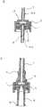
以下、本発明を図面を用いて具体的に説明するが、本発明は、以下に説明する具体的事例に限定されるものではない。また明細書において、気密とは、気体又は液体が漏れない意味に使用している。図1は、本発明の逆止弁を示す平面図及び断面図である。図1において、逆止弁Iは、環状のハウジングに収納するため、円形状の弾性体からなる逆止弁本体1の上流側及び下流側の各表面には中心に対して同芯円状に気密用環状突起41、42が形成されている。また中心には貫通孔3を有し、この貫通孔3は下流側の表面には長方形のスリットが形成されるが、この形状は船先形状であってもよい。また上流側の表面には、方形、例えば正方形31であって、該表面からスリット3に向かって傾斜する傾斜部2を有している(図1のa参照)。この傾斜部21、22はスリットの長手方向の辺に至る。したがって、図1のbの断面図でみると、傾斜部21、22は上流側から下流側へ向かってテーパーを形成している。ここで、弾性体としては、反撥弾性率が30〜80%の範囲のものが好ましい。使用される反撥弾性率の範囲は、反撥弾性率と圧縮配置するときの圧縮の度合いとによって個々に決められる。弾性体の好ましい材質としては、合成樹脂が挙げられ、特に好ましくはシリコーン、イソプロピレン、ポリウレタン、アクリロニトリル-ブタジエン系共重合体、フッ素樹脂等である。これらのうち、特に好ましいものは、シリコーン、イソプロピレンである。 Hereinafter, the present invention will be specifically described with reference to the drawings. However, the present invention is not limited to the specific examples described below. In the specification, airtight is used to mean that gas or liquid does not leak. FIG. 1 is a plan view and a sectional view showing a check valve of the present invention. In FIG. 1, since the check valve I is housed in an annular housing, the upstream and downstream surfaces of the check valve body 1 made of a circular elastic body are concentric with respect to the center. Airtight
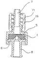
図2は、図1の逆止弁をハウジング内に収納した逆止弁ハウジングを示す断面図である。図3は、逆止弁を収納したハウジングの実施の形態の逆止弁ハウジングを示す断面図である。図4は、ロックリングを有する逆止弁ハウジングを示す断面図である。図2において、逆止弁を収納した逆止弁ハウジングIIは、逆止弁収納体5及び固定用蓋体6からなる逆止弁ハウジング中に逆止弁本体1が圧縮下に収納されている。即ち、逆止弁本体1の直径は、逆止弁収納体5の直径よりも僅かに大きく形成され、逆止弁収納体5には圧縮して挿入配置される。これによりスリット3は、後述するように、密着した状態で保持される。上流側から流入する気体又は液体の圧力により屈曲し開口され、流通するようになる。該収納体1は、具体的には上流側には傾斜部21、22を有する正方形の開口部31側が、また下流側には長方形のスリット3側がくるように配置収納される。また前記逆止弁収納体5は、下流側管状部を有すると共に、内部に逆止弁本体1を収納した際、下流側にスペース13が形成されるように空間部を有している。一方、固定用蓋体6は、該蓋体6の上流側には、上流側管状部8を有し、また蓋体6の前方、即ち下流側には先端部12を有しており、該先端部8は、逆止弁本体1の傾斜部21,22と実質的に平行な傾斜を有しており、傾斜部21、22の表面を押圧する押圧部9を有している。また蓋体6の周囲には環状突起11を有し、逆止弁収納体5の内壁に設けられた環状係合用凹部10に嵌合し固定される。本発明では、このような逆止弁ハウジングに収納された逆止弁1は、該ハウジング内で上流側表面及び下流側表面に有する気密用環状突起41、42により押圧されて気密が保持されると共に、逆止弁本体1の直径が逆止弁収納体の直径より僅かに大きく形成されているため圧縮された状態で収納されていることによりスリット3は密着又は押圧されて保持されている。このため気体又は液流が上流側から下流側へ流れるときは、逆止弁のスリット部分の弾性は、液圧に屈してひずみを生じ、開口して流通する。これに対して、下流側から上流側へ液流が流れようとするときは、スリット3は傾斜部分により厚みが増すと共に蓋体6の先端部12により押圧固定されているため、下流側から上流側へは屈曲しない。したがってスリット3は開口することができないので、液流は通過することができない。このように本発明は、逆止弁1の簡単な構造と逆止弁ハウジングにおける逆止弁収納体5と固定用蓋体6の簡単な構造の組み合わせにより従来のものに比して逆流防止に顕著な効果を奏するものである。 FIG. 2 is a sectional view showing a check valve housing in which the check valve of FIG. 1 is housed in the housing. FIG. 3 is a cross-sectional view showing a check valve housing according to an embodiment of a housing that houses a check valve. FIG. 4 is a cross-sectional view showing a check valve housing having a lock ring. In FIG. 2, the check valve housing II in which the check valve is accommodated has the check valve main body 1 housed under compression in a check valve housing comprising a
図3においては、逆止弁用ハウジングIIの、特に下流側環状部からなる回路接続部7と上流側環状部からなる回路接続部8の構造乃至形状を示したもので、図3のaは、回路接続部7、8は、平行環状突起(タケノコ)又は螺旋状ネジ溝14a、14bを有するものからなる。これにより所望の回路の樹脂管(又はパイプ)を確実に接続することができ、途中で管又はパイプが外れることがない。図3のbでは、回路接続部7、8において、下流側の回路接続部7は、係合部15を有し、また上流側の回路接続部8は、その端部にフランジ81を有しており、これらを設けることにより、接続管の接続を容易にし、また接続管が外れることを防止している。図4は、ロックリングを有する例であって、ロックリング16の内壁にはネジ山71を有しており、また内壁の端部には、回路接続部7に設けられた突起15と係合し、挿入固定される。このように設けられたロックリング16に回路やその他薬液用部材を接続する。 FIG. 3 shows the structure or shape of the check valve housing II, in particular, the
1 逆止弁本体
1a 蓋体上流側表面
1b 収納体下流側表面
2 開口部の傾斜部
21、22 傾斜部
3 スリット
31 方形(正方形)
41、42 気密用環状突起
5 逆止弁収納体
6 固定用蓋体
7 管状部(下流側)
8 管状部(上流側)
9 押圧部
10 環状係合凹部
11 環状突起
12 管先端部
13 スペース
14a、14b タケノコ
15 係合部
16 ロックリング
17 内壁突起
71 ネジ山
81 フランジ
I 逆止弁
II 逆止弁ハウジング
DESCRIPTION OF SYMBOLS 1 Check valve main body 1a Cover body upstream surface 1b Storage body
41, 42 Annular projections for
8 Tubular part (upstream side)
DESCRIPTION OF SYMBOLS 9
Claims (8)
Translated fromJapanesePriority Applications (1)
| Application Number | Priority Date | Filing Date | Title |
|---|---|---|---|
| JP2004026125AJP4494812B2 (en) | 2004-02-02 | 2004-02-02 | Check valve housing with flat check valve |
Applications Claiming Priority (1)
| Application Number | Priority Date | Filing Date | Title |
|---|---|---|---|
| JP2004026125AJP4494812B2 (en) | 2004-02-02 | 2004-02-02 | Check valve housing with flat check valve |
Publications (2)
| Publication Number | Publication Date |
|---|---|
| JP2005214406Atrue JP2005214406A (en) | 2005-08-11 |
| JP4494812B2 JP4494812B2 (en) | 2010-06-30 |
Family
ID=34908284
Family Applications (1)
| Application Number | Title | Priority Date | Filing Date |
|---|---|---|---|
| JP2004026125AExpired - Fee RelatedJP4494812B2 (en) | 2004-02-02 | 2004-02-02 | Check valve housing with flat check valve |
Country Status (1)
| Country | Link |
|---|---|
| JP (1) | JP4494812B2 (en) |
Cited By (5)
| Publication number | Priority date | Publication date | Assignee | Title |
|---|---|---|---|---|
| WO2008111356A1 (en)* | 2007-03-09 | 2008-09-18 | Asahi Rubber Inc. | Excessive pressure relief valve, and relief valve unit having the relief valve |
| JP2010144769A (en)* | 2008-12-17 | 2010-07-01 | Asahi Rubber Inc | Excessive pressure relief valve and excessive pressure relief unit including the same |
| JP2010181028A (en)* | 2009-01-08 | 2010-08-19 | Corona Giken Kogyo Kk | Check valve |
| KR101487897B1 (en)* | 2012-11-14 | 2015-01-30 | 엘케이메디칼(주) | Catheter for preventing regurgitation of blood |
| WO2015125987A1 (en)* | 2014-02-21 | 2015-08-27 | 엘케이메디칼(주) | Syringe integrated with filter needle, blood backflow prevention device and venous catheter having blood backflow prevention device |
Citations (6)
| Publication number | Priority date | Publication date | Assignee | Title |
|---|---|---|---|---|
| DE571874C (en)* | 1933-03-06 | Carlshuette Akt Ges Fuer Eisen | Rubber lip valve | |
| JPS4990554A (en)* | 1972-12-07 | 1974-08-29 | ||
| US4143853A (en)* | 1977-07-14 | 1979-03-13 | Metatech Corporation | Valve for use with a catheter or the like |
| JPS61228173A (en)* | 1985-02-21 | 1986-10-11 | ヴア−ネイ・ラボラトリ−ズ・インコ−ポレ−テツド | Valve assembly |
| JP2002000700A (en)* | 1999-10-05 | 2002-01-08 | Otsuka Pharmaceut Factory Inc | Cap and drug container using the same |
| JP2003339876A (en)* | 2002-05-28 | 2003-12-02 | Nipro Corp | Mixing injector |
- 2004
- 2004-02-02JPJP2004026125Apatent/JP4494812B2/ennot_activeExpired - Fee Related
Patent Citations (6)
| Publication number | Priority date | Publication date | Assignee | Title |
|---|---|---|---|---|
| DE571874C (en)* | 1933-03-06 | Carlshuette Akt Ges Fuer Eisen | Rubber lip valve | |
| JPS4990554A (en)* | 1972-12-07 | 1974-08-29 | ||
| US4143853A (en)* | 1977-07-14 | 1979-03-13 | Metatech Corporation | Valve for use with a catheter or the like |
| JPS61228173A (en)* | 1985-02-21 | 1986-10-11 | ヴア−ネイ・ラボラトリ−ズ・インコ−ポレ−テツド | Valve assembly |
| JP2002000700A (en)* | 1999-10-05 | 2002-01-08 | Otsuka Pharmaceut Factory Inc | Cap and drug container using the same |
| JP2003339876A (en)* | 2002-05-28 | 2003-12-02 | Nipro Corp | Mixing injector |
Cited By (8)
| Publication number | Priority date | Publication date | Assignee | Title |
|---|---|---|---|---|
| WO2008111356A1 (en)* | 2007-03-09 | 2008-09-18 | Asahi Rubber Inc. | Excessive pressure relief valve, and relief valve unit having the relief valve |
| JPWO2008111356A1 (en)* | 2007-03-09 | 2010-06-24 | 株式会社朝日ラバー | Overpressure release valve and release valve unit having the same |
| JP5111490B2 (en)* | 2007-03-09 | 2013-01-09 | 株式会社朝日ラバー | Overpressure release valve and release valve unit having the same |
| US8443840B2 (en) | 2007-03-09 | 2013-05-21 | Asahi Rubber Inc. | Excessive pressure release valve and release valve unit having the release valve |
| JP2010144769A (en)* | 2008-12-17 | 2010-07-01 | Asahi Rubber Inc | Excessive pressure relief valve and excessive pressure relief unit including the same |
| JP2010181028A (en)* | 2009-01-08 | 2010-08-19 | Corona Giken Kogyo Kk | Check valve |
| KR101487897B1 (en)* | 2012-11-14 | 2015-01-30 | 엘케이메디칼(주) | Catheter for preventing regurgitation of blood |
| WO2015125987A1 (en)* | 2014-02-21 | 2015-08-27 | 엘케이메디칼(주) | Syringe integrated with filter needle, blood backflow prevention device and venous catheter having blood backflow prevention device |
Also Published As
| Publication number | Publication date |
|---|---|
| JP4494812B2 (en) | 2010-06-30 |
Similar Documents
| Publication | Publication Date | Title |
|---|---|---|
| JP6273209B2 (en) | Piston for needleless valve system | |
| CN109562253B (en) | Needle assembly with valve and indwelling needle assembly | |
| US8298195B2 (en) | Needleless access port valve | |
| CA2275218C (en) | Positive flow valve | |
| JP6163198B2 (en) | cap | |
| US9855411B2 (en) | Connector and infusion set | |
| WO2013099261A1 (en) | Needleless connector | |
| CN108392730A (en) | Anury formula needless valve system | |
| US11458291B2 (en) | Connector and infusion set | |
| JP2016013359A (en) | Hub assembly with bulkhead member | |
| JP4494812B2 (en) | Check valve housing with flat check valve | |
| WO2005120630A1 (en) | Connector | |
| AU2016348087B2 (en) | Syringe | |
| JP3759735B2 (en) | Medical check valve | |
| JP6670437B2 (en) | Needleless connector | |
| US10413663B2 (en) | Automatic anti-free-flow valve for medical pumps | |
| JP4728809B2 (en) | Connector | |
| US20130204215A1 (en) | Valve for Regulating the Flow of A Liquid | |
| US20230256206A1 (en) | Outer needle assembly | |
| JP6154336B2 (en) | Check valve | |
| JP6924368B2 (en) | Male connector | |
| TWM488317U (en) | Male luer connector that prevents leakage of liquid medicine | |
| JP7356444B2 (en) | How to use capped connectors, caps, and capped connectors | |
| JP2006061673A (en) | Back-flow valve structure | |
| JP7286495B2 (en) | medical connector |
Legal Events
| Date | Code | Title | Description |
|---|---|---|---|
| A621 | Written request for application examination | Free format text:JAPANESE INTERMEDIATE CODE: A621 Effective date:20061225 | |
| A977 | Report on retrieval | Free format text:JAPANESE INTERMEDIATE CODE: A971007 Effective date:20090820 | |
| A131 | Notification of reasons for refusal | Free format text:JAPANESE INTERMEDIATE CODE: A131 Effective date:20090917 | |
| A521 | Written amendment | Free format text:JAPANESE INTERMEDIATE CODE: A523 Effective date:20091116 | |
| A131 | Notification of reasons for refusal | Free format text:JAPANESE INTERMEDIATE CODE: A131 Effective date:20100118 | |
| A521 | Written amendment | Free format text:JAPANESE INTERMEDIATE CODE: A523 Effective date:20100121 | |
| TRDD | Decision of grant or rejection written | ||
| A01 | Written decision to grant a patent or to grant a registration (utility model) | Free format text:JAPANESE INTERMEDIATE CODE: A01 Effective date:20100331 | |
| A01 | Written decision to grant a patent or to grant a registration (utility model) | Free format text:JAPANESE INTERMEDIATE CODE: A01 | |
| A61 | First payment of annual fees (during grant procedure) | Free format text:JAPANESE INTERMEDIATE CODE: A61 Effective date:20100408 | |
| R150 | Certificate of patent (=grant) or registration of utility model | Free format text:JAPANESE INTERMEDIATE CODE: R150 | |
| FPAY | Renewal fee payment (prs date is renewal date of database) | Free format text:PAYMENT UNTIL: 20130416 Year of fee payment:3 | |
| LAPS | Cancellation because of no payment of annual fees |