JP2005211819A - Porous element and air purification device - Google Patents
Porous element and air purification deviceDownload PDFInfo
- Publication number
- JP2005211819A JP2005211819AJP2004023127AJP2004023127AJP2005211819AJP 2005211819 AJP2005211819 AJP 2005211819AJP 2004023127 AJP2004023127 AJP 2004023127AJP 2004023127 AJP2004023127 AJP 2004023127AJP 2005211819 AJP2005211819 AJP 2005211819A
- Authority
- JP
- Japan
- Prior art keywords
- water
- air
- porous element
- porous
- communication port
- Prior art date
- Legal status (The legal status is an assumption and is not a legal conclusion. Google has not performed a legal analysis and makes no representation as to the accuracy of the status listed.)
- Pending
Links
Images


Landscapes
- Separation Using Semi-Permeable Membranes (AREA)
- Air Humidification (AREA)
Abstract
Translated fromJapaneseDescription
Translated fromJapanese本発明は、多孔質エレメント及びこれを備えて空気からの水溶性ガスの除去等を行う空気浄化装置に関する。 The present invention relates to a porous element and an air purification apparatus that includes the porous element and removes a water-soluble gas from air.
従来より、特許文献1に開示されているように、冷蔵庫の庫内を加湿する加湿装置が知られている。この加湿装置は、冷蔵庫の内壁に取り付けられている。加湿装置のケーシングには、多孔質エレメントである加湿エレメントが収納されている。加湿エレメントには、多孔質膜から成るチューブが多数設けられている。加湿エレメントでは、下部の入口ヘッダから上部の出口ヘッダに亘ってチューブが設けられており、このチューブ内を水が流れる。また、入口ヘッダと出口ヘッダとには、水配管を接続するための開口が形成されている。そして、加湿エレメントでは、チューブ内の水の一部が水蒸気となってチューブを通過し、チューブを通過した水蒸気が空気へ付与される。 Conventionally, as disclosed in Patent Document 1, a humidifier that humidifies the interior of a refrigerator is known. This humidifier is attached to the inner wall of the refrigerator. A humidifying element, which is a porous element, is accommodated in the casing of the humidifying device. The humidifying element is provided with a number of tubes made of a porous membrane. In the humidifying element, a tube is provided from the lower inlet header to the upper outlet header, and water flows through the tube. Moreover, the opening for connecting water piping is formed in the inlet header and the outlet header. And in a humidification element, a part of water in a tube turns into water vapor | steam, passes a tube, and the water vapor | steam which passed the tube is provided to air.
また、上記加湿エレメントにおいて、チューブ内に空気を、チューブ外に水を流すようにしてもよい。この場合、加湿エレメントには、中空の容器と、該容器を貫通するチューブとが設けられる。そして、容器に水の入口となる開口と水の出口となる開口とが1つずつ形成される。
上記特許文献1に記載されたような多孔質エレメントを備えた装置については、能力の異なる複数の機種を生産するケースが多い。そして、このような装置の能力を変更する方策としては、多孔質エレメント自体の大きさを変える方策と、多孔質エレメントの個数を変更する方策とが考えられる。 In many cases, a device having a porous element as described in Patent Document 1 produces a plurality of models having different capacities. And as a measure for changing the capability of such an apparatus, a measure for changing the size of the porous element itself and a measure for changing the number of the porous elements can be considered.
しかしながら、多孔質エレメントの大きさを変える方策では、多孔質エレメントの設計を能力ごとに行わなければならない。また、多孔質エレメントが機種ごとの専用品となるため、多孔質エレメントやこれを備える装置の製造コストが上昇してしまう。 However, in the strategy of changing the size of the porous element, the porous element must be designed for each capacity. In addition, since the porous element becomes a dedicated product for each model, the manufacturing cost of the porous element and the apparatus including the same increases.
一方、多孔質エレメントの個数を変更する方策では、個々の多孔質エレメントにおける水の入口と出口の位置が一通りに決まっており、入口から出口へ至るまでの水の流通経路も一通りに決まってしまう。このため、複数ある多孔質エレメントの並べ方が一通りとなり、多孔質エレメントの配置自由度が小さい。このように、多孔質エレメントの配置の制約が大きいためにその使い勝手が悪いという問題があった。 On the other hand, in the strategy of changing the number of porous elements, the positions of water inlets and outlets in each porous element are determined in a single way, and the water flow path from the inlet to the outlet is also determined in a single way. End up. For this reason, the plurality of porous elements are arranged in a single way, and the degree of freedom in arranging the porous elements is small. As described above, there is a problem in that the use of the porous elements is large and the usability thereof is poor.
本発明はかかる点に鑑みてなされたものであり、その目的とするところは、多孔質エレメントの部品を共通化してコスト削減を図ると共に、多孔質エレメントの配置自由度を確保してその使い勝手を向上させることにある。 The present invention has been made in view of the above points, and the object of the present invention is to reduce the cost by making the parts of the porous element common, and to ensure the degree of freedom of arrangement of the porous element and to improve its usability. There is to improve.
第1の発明は、多孔質膜で構成されたチューブ部材(72)と、中空の柱状に形成されて一方の端面から他方の端面へ該チューブ部材(72)が貫通する容器部材(71)とを備え、上記チューブ部材(72)の内側が空気通路(73)となって該チューブ部材(72)の外側が水通路(74)となる多孔質エレメントを対象としている。そして、上記容器部材(71)は、上記水通路(74)の入口又は出口となる開口が側面に形成されており、上記水通路(74)の入口から出口に至る水の流通経路が複数通り設定可能に構成されるものである。 The first invention comprises a tube member (72) made of a porous membrane, and a container member (71) formed in a hollow column shape through which the tube member (72) penetrates from one end surface to the other end surface. And a porous element in which the inside of the tube member (72) serves as an air passage (73) and the outside of the tube member (72) serves as a water passage (74). The container member (71) has an opening on the side surface that serves as an inlet or outlet of the water passage (74), and there are a plurality of water flow paths from the inlet to the outlet of the water passage (74). It is configured to be configurable.
第2の発明は、多孔質膜で構成されたチューブ部材(72)と、端面が多角形の柱状に形成されて一方の端面から他方の端面へ該チューブ部材(72)が貫通する容器部材(71)とを備え、上記チューブ部材(72)の内側が空気通路(73)となって該チューブ部材(72)の外側が水通路(74)となる多孔質エレメントを対象としている。そして、上記容器部材(71)の各側面には、上記水通路(74)に連通する連通口(93,94,…)が1つずつ設けられるものである。 According to a second aspect of the present invention, there is provided a tube member (72) formed of a porous membrane, and a container member (the end surface of which is formed in a polygonal column shape, and the tube member (72) penetrates from one end surface to the other end surface) 71), and a porous element in which the inside of the tube member (72) is an air passage (73) and the outside of the tube member (72) is a water passage (74). And each communication port (93, 94, ...) connected to the said water channel (74) is provided in each side surface of the said container member (71) 1 each.
第3の発明は、第2の発明において、容器部材(71)は、第1の側面(83)と第2の側面(84)が対向して第3の側面(85)と第4の側面(86)が対向する四角柱状に形成され、第1の側面(83)では第3の側面(85)と第1の端面(81)とに近接した隅角部に第1の連通口(93)が、第2の側面(84)では第4の側面(86)と第2の端面(82)とに近接した隅角部に第2の連通口(94)が、第3の側面(85)では第2の側面(84)と第1の端面(81)とに近接した隅角部に第3の連通口(95)が、第4の側面(86)では第1の側面(83)と第2の端面(82)とに近接した隅角部に第4の連通口(96)がそれぞれ設けられるものである。 According to a third aspect, in the second aspect, the container member (71) is configured such that the first side surface (83) and the second side surface (84) face each other, and the third side surface (85) and the fourth side surface. (86) is formed in an opposing quadrangular prism shape, and in the first side surface (83), a first communication port (93 is formed in a corner near the third side surface (85) and the first end surface (81). ) On the second side surface (84), the second communication port (94) is provided at the corner portion adjacent to the fourth side surface (86) and the second end surface (82), and the third side surface (85). ) Has a third communication port (95) at a corner close to the second side surface (84) and the first end surface (81), and the fourth side surface (86) has a first side surface (83). And a fourth communication port (96) is provided at each corner near the second end surface (82).
第4の発明は、空気浄化装置を対象としている。そして、規格化された第2又は第3の発明に記載の多孔質エレメント(70)を複数備え、各多孔質エレメント(70)では、2つの連通口(93,94,…)だけが開口して残りの連通口(93,94,…)が蓋部材(76)によって閉塞され、上記複数の多孔質エレメント(70)は、それぞれの端面が同じ向きとなるように配列されると共に、隣接する多孔質エレメント(70)の水通路(74)同士が開口した連通口(93,94,…)を介して連通され、上記各多孔質エレメント(70)では、チューブ部材(72)を通過した水溶性ガスを水通路(74)の水に溶解させて空気通路(73)の空気から除去し、上記チューブ部材(72)を通過した水蒸気によって上記空気通路(73)の空気を加湿すると共に、上記水通路(74)の水との熱交換によって上記空気通路(73)の空気を冷却する動作が行われるものである。 The fourth invention is directed to an air purification device. A plurality of standardized porous elements (70) according to the second or third invention are provided, and in each porous element (70), only two communication ports (93, 94,...) Are opened. The remaining communication ports (93, 94,...) Are closed by the lid member (76), and the plurality of porous elements (70) are arranged so that the end faces thereof are in the same direction and are adjacent to each other. The water passages (74) of the porous element (70) communicate with each other through open communication ports (93, 94,...), And each porous element (70) has a water solution that has passed through the tube member (72). The characteristic gas is dissolved in the water in the water passage (74) and removed from the air in the air passage (73), and the air in the air passage (73) is humidified by the water vapor that has passed through the tube member (72). The air in the air passage (73) is cooled by heat exchange with water in the water passage (74). The operation is performed.
−作用−
上記第1及び第2の発明では、多孔質エレメントにチューブ部材(72)と容器部材(71)とが設けられる。容器部材(71)は、中空の柱状に形成されている。チューブ部材(72)は、容器部材(71)の一方の端面から他方の端面に亘って設けられており、該容器部材(71)の各端面に開口している。そして、多孔質エレメントでは、チューブ部材(72)の内側が空気通路(73)となっており、チューブ部材(72)の外側、即ち該チューブ部材(72)の外周面と容器部材(71)の内面とに囲まれた部分が水通路(74)となっている。-Action-
In the first and second inventions, the porous element is provided with the tube member (72) and the container member (71). The container member (71) is formed in a hollow column shape. The tube member (72) is provided from one end surface of the container member (71) to the other end surface, and is open to each end surface of the container member (71). In the porous element, the inside of the tube member (72) is an air passage (73), and the outside of the tube member (72), that is, the outer peripheral surface of the tube member (72) and the container member (71). A portion surrounded by the inner surface is a water passage (74).
上記第1の発明において、容器部材(71)には、水通路(74)の入口又は出口となる開口が形成されている。この開口は、容器部材(71)の端面ではなく、その側面に形成されている。多孔質エレメントにおいて、水通路(74)の入口となる開口から水通路(74)へ流入した水は、水通路(74)の出口となる開口へ向かって流れる。多孔質エレメントの水通路(74)では、入口となる開口と出口となる開口とを選択することによって、入口から出口に至る水の流通経路が複数通り設定可能となっている。 In the first invention, the container member (71) is formed with an opening that serves as an inlet or an outlet of the water passage (74). This opening is formed not on the end face of the container member (71) but on its side face. In the porous element, the water flowing into the water passage (74) from the opening serving as the inlet of the water passage (74) flows toward the opening serving as the outlet of the water passage (74). In the water passage (74) of the porous element, a plurality of water flow paths from the inlet to the outlet can be set by selecting an opening serving as the inlet and an opening serving as the outlet.
上記第2の発明において、容器部材(71)は、端面が多角形となる柱状に形成されると共に、水通路(74)に連通する連通口(93,94,…)を備えている。この連通口(93,94,…)は、容器部材(71)の端面ではなく、その各側面に1つずつ設けられている。容器部材(71)の各側面に開口する連通口(93,94,…)は、そのうちの1つが水通路(74)の入口となって他の1つが水通路(74)の出口となり、残りが閉塞される。水通路(74)では、その入口から出口へ向かって水が流れる。多孔質エレメントにおいて、水通路(74)の入口となる連通口(93,94,…)と出口となる連通口(93,94,…)とを選択すれば、入口から出口に至る水の流通経路が複数通り設定可能となる。 In the second aspect of the invention, the container member (71) is formed in a columnar shape whose end surface is a polygon, and includes communication ports (93, 94,...) Communicating with the water passage (74). The communication ports (93, 94,...) Are not provided on the end surface of the container member (71), but one on each side thereof. The communication ports (93, 94,...) That open on the side surfaces of the container member (71), one of which is the inlet of the water passage (74) and the other is the outlet of the water passage (74), and the rest Is blocked. In the water passage (74), water flows from the inlet to the outlet. In the porous element, if the communication port (93,94, ...) that becomes the inlet of the water passage (74) and the communication port (93,94, ...) that becomes the outlet are selected, the flow of water from the inlet to the outlet Multiple routes can be set.
上記第3の発明では、容器部材(71)が四角柱状に形成され、4つの側面のそれぞれの隅角部に連通口(93,94,…)が設けられる。具体的に、第1及び第3の連通口(93,95)は、第1の端面(81)寄りに形成される。また、第3の連通口(95)は、第2の側面(84)寄り、即ち第3の側面(85)における第1の連通口(93)から離れた側の隅角部に形成される。第2及び第4の連通口(94,96)は、第2の端面(82)寄りに形成される。また、第4の連通口(96)は、第1の側面(83)寄り、即ち第4の側面(86)における第2の連通口(94)から離れた側の隅角部に形成される。 In the third invention, the container member (71) is formed in a quadrangular prism shape, and the communication ports (93, 94,...) Are provided at the corners of the four side surfaces. Specifically, the first and third communication ports (93, 95) are formed closer to the first end surface (81). The third communication port (95) is formed near the second side surface (84), that is, at the corner portion of the third side surface (85) on the side away from the first communication port (93). . The second and fourth communication ports (94, 96) are formed closer to the second end surface (82). The fourth communication port (96) is formed near the first side surface (83), that is, at the corner of the fourth side surface (86) on the side away from the second communication port (94). .
上記第4の発明では、空気浄化装置に複数の多孔質エレメント(70)が設けられる。各多孔質エレメント(70)は、それぞれが規格化されており、その大きさや形状が全て等しくなっている。各多孔質エレメント(70)では、水通路(74)へ水が流入する連通口(93,94,…)と水通路(74)から水が流出する連通口(93,94,…)以外の連通口(93,94,…)が、蓋部材(76)によって閉塞されている。また、各多孔質エレメント(70)は、それぞれの端面が同じ向きとなるように配列される一方、隣接する多孔質エレメント(70)の開口した連通口(93,94,…)が対向するように配置されている。そして、隣接する多孔質エレメント(70)の水通路(74)同士は、開口した連通口(93,94,…)を介して連通している。 In the fourth aspect of the invention, the air purification device is provided with a plurality of porous elements (70). Each porous element (70) is standardized, and the size and shape are all equal. Each porous element (70) has a communication port (93,94, ...) through which water flows into the water passage (74) and a communication port (93,94, ...) through which water flows out from the water passage (74). The communication port (93, 94,...) Is closed by the lid member (76). In addition, the porous elements (70) are arranged so that the end faces thereof are in the same direction, while the communication ports (93, 94,...) Opened by the adjacent porous elements (70) face each other. Is arranged. The water passages (74) of the adjacent porous elements (70) communicate with each other through open communication ports (93, 94, ...).
各多孔質エレメント(70)では、隣接する一方の多孔質エレメントの水通路(74)を流通する水が連通口(93,94,…)を通って隣接する他方の多孔質エレメント(70)の水通路(74)へと流れる。この際、各多孔質エレメント(70)において、空気通路(73)の空気に含まれる水溶性ガスは、チューブ部材(72)を通過して水通路(74)の水に溶解する。このようにして、空気通路(73)を流通する空気から水溶性ガスが除去される。 In each porous element (70), the water flowing through the water passage (74) of one adjacent porous element passes through the communication port (93, 94,...) Of the other adjacent porous element (70). It flows to the water passage (74). At this time, in each porous element (70), the water-soluble gas contained in the air in the air passage (73) passes through the tube member (72) and dissolves in the water in the water passage (74). In this way, the water-soluble gas is removed from the air flowing through the air passage (73).
一方、水通路(74)を流通する水は、その一部が水蒸気となってチューブ部材(72)を通過する。チューブ部材(72)を通過した水蒸気は、空気通路(73)の空気へ付与される。このようにして、空気通路(73)を流通する空気が加湿される。 On the other hand, the water flowing through the water passage (74) partially passes through the tube member (72) as water vapor. The water vapor that has passed through the tube member (72) is imparted to the air in the air passage (73). In this way, the air flowing through the air passage (73) is humidified.
空気通路(73)を流通する空気は、水通路(74)を流通する水とチューブ部材(72)を介して熱交換を行う。水通路(74)には、空気通路(73)を流通する空気よりも温度の低い水が供給される。このため、空気通路(73)を流通する空気は、水通路(74)を流通する水へ放熱し、冷却される。また、空気通路(73)を流通する空気は、水の蒸発による蒸発潜熱によっても冷却される。このように、上記空気浄化装置では、各多孔質エレメント(70)において空気からの水溶性ガスの除去と、空気の加湿と冷却とが行われる。 The air flowing through the air passage (73) exchanges heat with the water flowing through the water passage (74) through the tube member (72). Water having a temperature lower than that of the air flowing through the air passage (73) is supplied to the water passage (74). For this reason, the air flowing through the air passage (73) dissipates heat to the water flowing through the water passage (74) and is cooled. Further, the air flowing through the air passage (73) is also cooled by the latent heat of evaporation due to the evaporation of water. As described above, in the air purification device, the water-soluble gas is removed from the air, and the air is humidified and cooled in each porous element (70).
上記第1の発明では、水通路(74)の入口となる開口と出口となる開口とを選択することによって、水通路(74)の入口から出口に至る水の流通経路が複数通り設定可能となっている。一方、上記第2の発明において、水通路(74)の入口となる連通口(93,94,…)と出口となる連通口(93,94,…)とを選択すれば、水通路(74)の入口から出口に至る水の流通経路が複数通り設定可能となる。 In the first aspect of the invention, by selecting an opening that serves as an inlet and an outlet that serves as an outlet of the water passage (74), a plurality of water flow paths from the inlet to the outlet of the water passage (74) can be set. It has become. On the other hand, in the second aspect of the invention, if the communication port (93, 94,...) Serving as the inlet of the water channel (74) and the communication port (93, 94,...) Serving as the outlet are selected, the water channel (74 ) Can be set in multiple ways.
よって、例えば複数の多孔質エレメントを並べて配置する場合には、多孔質エレメントの配置に応じて水通路(74)における水の流通経路を選択することが可能となる。このため、複数の多孔質エレメントの水通路(74)を互いに接続する使い方をする場合でも、多孔質エレメントの配置を最適化することが可能となり、多孔質エレメントの使い勝手を向上させることができる。 Therefore, for example, when a plurality of porous elements are arranged side by side, it is possible to select a water flow path in the water passage (74) according to the arrangement of the porous elements. Therefore, even when the water passages (74) of a plurality of porous elements are connected to each other, the arrangement of the porous elements can be optimized, and the usability of the porous elements can be improved.
上記第4の発明では、空気浄化装置に規格化された多孔質エレメント(70)を複数設け、各多孔質エレメント(70)のチューブ部材(72)を介して空気からの水溶性ガスの除去と、空気の加湿及び冷却とを行っている。従って、この発明によれば、規格化された多孔質エレメント(70)の数を増減することで、能力の異なる空気浄化装置を容易に構成できる。また、複数ある多孔質エレメント(70)の部品を共通化することにより、多孔質エレメント(70)やこれを備える空気浄化装置の製造コストの削減を図ることができる。 In the fourth aspect of the invention, a plurality of standardized porous elements (70) are provided in the air purification device, and water-soluble gas is removed from the air via the tube member (72) of each porous element (70). The air is humidified and cooled. Therefore, according to the present invention, it is possible to easily construct an air purifier having different capabilities by increasing or decreasing the number of standardized porous elements (70). In addition, by sharing a plurality of parts of the porous element (70), it is possible to reduce the manufacturing cost of the porous element (70) and the air purification apparatus including the same.
以下、本発明の実施形態を図面に基づいて詳細に説明する。 Hereinafter, embodiments of the present invention will be described in detail with reference to the drawings.
《発明の実施形態》
図1に示すように、本実施形態の空気浄化装置(10,20)は、半導体デバイス等の精密機器を製造するクリーンルーム棟(50)に設置されている。このクリーンルーム棟(50)は、天井チャンバ(51)と、クリーンルーム(52)と、クリーンルーム(52)の床下であるリターンプレナム(53)と、天井チャンバ(51)とリターンプレナム(53)を接続するリターンシャフト(54)とに区画されている。また、天井チャンバ(51)には、空気中の塵埃を除去するためのファンフィルタユニット(61)が取り付けられている。そして、クリーンルーム棟(50)では、クリーンルーム(52)、リターンプレナム(53)、リターンシャフト(54)、天井チャンバ(51)、ファンフィルタユニット(61)、及びクリーンルーム(52)の順に空気が循環する。<< Embodiment of the Invention >>
As shown in FIG. 1, the air purification apparatus (10, 20) of this embodiment is installed in a clean room building (50) that manufactures precision equipment such as semiconductor devices. This clean room building (50) connects the ceiling chamber (51), the clean room (52), the return plenum (53) under the floor of the clean room (52), and the ceiling chamber (51) and the return plenum (53). It is partitioned into a return shaft (54). A fan filter unit (61) for removing dust in the air is attached to the ceiling chamber (51). In the clean room building (50), air circulates in the order of the clean room (52), the return plenum (53), the return shaft (54), the ceiling chamber (51), the fan filter unit (61), and the clean room (52). .
上記クリーンルーム(52)内には、移動可能な移動型空気浄化装置(10)が設置されている。また、上記リターンプレナム(53)には、その床面に横置き型空気浄化装置(20)が設置されている。これら空気浄化装置(10,20)について、順に説明する。 In the clean room (52), a movable mobile air purification device (10) is installed. The return plenum (53) is provided with a horizontal air purifier (20) on its floor. These air purifiers (10, 20) will be described in order.
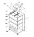
まず、図2に示すように、上記移動型空気浄化装置(10)は、縦長に形成された直方体状のケーシング(11)を備えている。ケーシング(11)の上面には、吹出口(12)が設けられている。ケーシング(11)の側面の下部には、メッシュ状に形成された吸込口(13)が設けられている。この吹出口(12)や吸込口(13)を介して、ケーシング(11)の内部とクリーンルーム(52)内とが連通する。この移動型空気浄化装置(10)は、ケーシング(11)の下面に車輪(14)を備えており、クリーンルーム(52)内を自由に移動できるようになっている。 First, as shown in FIG. 2, the mobile air purification device (10) includes a rectangular parallelepiped casing (11) formed in a vertically long shape. A blower outlet (12) is provided on the upper surface of the casing (11). A suction port (13) formed in a mesh shape is provided at the lower part of the side surface of the casing (11). The inside of the casing (11) and the inside of the clean room (52) communicate with each other through the air outlet (12) and the suction port (13). The mobile air purification device (10) includes a wheel (14) on the lower surface of the casing (11), and can freely move in the clean room (52).
上記ケーシング(11)の内部には、ファン(15)と、ヘッドタンク(16)と、浄化用ユニット(17)と、該浄化用ユニット(17)を支持するフレーム(18)とが設けられている。 Inside the casing (11), a fan (15), a head tank (16), a purification unit (17), and a frame (18) for supporting the purification unit (17) are provided. Yes.
具体的に、ケーシング(11)の内部では、その床面にヘッドタンク(16)が立設されている。ヘッドタンク(16)は、ケーシング(11)の側面に沿うように設置され、その高さがケーシング(11)の高さの概ね2/3程度となっている。ヘッドタンク(16)の側面のうちケーシング(11)に沿う側面と反対側の側面には、3つのフレーム(18)が異なる高さに取り付けられている。最も高い位置に取り付けられたフレーム(18)は、その高さがヘッドタンク(16)の高さと概ね等しくなっている。最も低い位置に取り付けられたフレーム(18)は、その高さが吸込口(13)の上端よりも高くなっている。 Specifically, a head tank (16) is erected on the floor surface inside the casing (11). The head tank (16) is installed along the side surface of the casing (11), and its height is about 2/3 of the height of the casing (11). Three frames (18) are attached to different heights on the side surface of the head tank (16) opposite to the side surface along the casing (11). The height of the frame (18) mounted at the highest position is approximately equal to the height of the head tank (16). The height of the frame (18) attached to the lowest position is higher than the upper end of the suction port (13).
各フレーム(18)には、浄化用ユニット(17)が1つずつ設置されている。この浄化用ユニット(17)は、4個の多孔質エレメント(70)によって構成されている。つまり、ケーシング(11)内には、12個の多孔質エレメント(70)が設置されている。これら多孔質エレメント(70)は、ヘッドタンク(16)の側面とフレーム(18)とに周りを囲まれており、このフレーム(18)によって支持されている。 Each frame (18) is provided with one purification unit (17). The purification unit (17) is composed of four porous elements (70). That is, twelve porous elements (70) are installed in the casing (11). These porous elements (70) are surrounded by the side surface of the head tank (16) and the frame (18), and are supported by the frame (18).
図3に示すように、各多孔質エレメント(70)は、容器部材(71)とチューブ部材(72)とを備えている。容器部材(71)は直方体状に形成されており、内部が中空となっている。尚、図3において、容器部材(71)では、その上面が第2の端面(82)となりその下面が第1の端面(81)となる一方、その手前右側の面が第1の側面(83)となり、その奥左側の面が第2の側面(84)となり、その手前左側の面が第3の側面(85)となり、その奥右側の面が第4の側面(86)となっている。そして、第1の端面(81)と第2の端面(82)とが対向し、第1の側面(83)と第2の側面(84)とが対向し、第3の側面(85)と第4の側面(86)とが対向している。 As shown in FIG. 3, each porous element (70) includes a container member (71) and a tube member (72). The container member (71) is formed in a rectangular parallelepiped shape and is hollow inside. In FIG. 3, the upper surface of the container member (71) is the second end surface (82) and the lower surface is the first end surface (81), while the right front surface is the first side surface (83). ), The back left side is the second side surface (84), the front left side surface is the third side surface (85), and the back right side surface is the fourth side surface (86). . The first end face (81) and the second end face (82) face each other, the first side face (83) and the second side face (84) face each other, and the third side face (85) The fourth side surface (86) is opposed.
上記チューブ部材(72)は円筒状に形成されている。チューブ部材(72)は、容器部材(71)の第1の端面(81)から第2の端面(82)に亘って設けられており、該容器部材(71)の各端面に開口している。このチューブ部材(72)は、疎水性多孔質膜で構成されている。疎水性多孔質膜は、ポリテトラフルオロエチレン(PTFE)等のフッ素樹脂製である。この疎水性多孔質膜には、多数の微小孔が形成されている。 The tube member (72) is formed in a cylindrical shape. The tube member (72) is provided from the first end surface (81) to the second end surface (82) of the container member (71), and is open to each end surface of the container member (71). . The tube member (72) is composed of a hydrophobic porous membrane. The hydrophobic porous membrane is made of a fluororesin such as polytetrafluoroethylene (PTFE). A large number of micropores are formed in this hydrophobic porous membrane.
上記チューブ部材(72)の内側は、空気が流通する空気通路(73)となっている。上記チューブ部材(72)の外側、即ち該チューブ部材(72)の外周面と容器部材(71)の内面とに囲まれた部分は、水が流通する水通路(74)となっている。そして、多孔質エレメント(70)は、空気通路(73)を流通する空気と水通路(74)を流通する水とがチューブ部材(72)を介して接触するように構成されている。 Inside the tube member (72) is an air passage (73) through which air flows. The outside of the tube member (72), that is, the portion surrounded by the outer peripheral surface of the tube member (72) and the inner surface of the container member (71) is a water passage (74) through which water flows. And the porous element (70) is comprised so that the air which distribute | circulates an air channel | path (73) and the water which distribute | circulates a water channel | path (74) may contact via a tube member (72).
本実施形態の多孔質エレメント(70)では、容器部材(71)の各側面に連通口(93,94,…)が設けられている。各連通口(93,94,…)は、水通路(74)と連通している。具体的に、第1の側面(83)では、第3の側面(85)と第1の端面(81)とに近接した隅角部に第1の連通口(93)が設けられている。第2の側面(84)では、第4の側面(86)と第2の端面(82)とに近接した隅角部に第2の連通口(94)が設けられている。第3の側面(85)では、第2の側面(84)と第1の端面(81)とに近接した隅角部に第3の連通口(95)が設けられている。第4の側面(86)では、第1の側面(83)と第2の端面(82)とに近接した隅角部に第4の連通口(96)が設けられている。 In the porous element (70) of the present embodiment, communication ports (93, 94,...) Are provided on each side surface of the container member (71). Each communication port (93, 94,...) Communicates with the water passage (74). Specifically, in the first side surface (83), a first communication port (93) is provided at a corner portion close to the third side surface (85) and the first end surface (81). In the second side surface (84), a second communication port (94) is provided at a corner near the fourth side surface (86) and the second end surface (82). In the third side surface (85), a third communication port (95) is provided at a corner near the second side surface (84) and the first end surface (81). In the fourth side surface (86), a fourth communication port (96) is provided at a corner near the first side surface (83) and the second end surface (82).
また、図4に示すように、容器部材(71)の各側面では、開口した2つの連通口(93,94,…)、即ち水通路(74)に水が流入する連通口(93,94,…)と水通路(74)から水が流出する連通口(93,94,…)とに環状の接続具(75)が嵌め込まれている。残りの2つの連通口(93,94,…)には、該連通口(93,94,…)を閉塞するための蓋部材(76)が嵌め込まれている。上記接続具(75)は、隣接する多孔質エレメント(70)の容器部材(71)同士を接続するためのものである。そして、この接続具(75)を互いに接続することによって隣接する多孔質エレメント(70)の容器部材(71)同士が接続され、互いの水通路(74)が連通口(93,94,…)を介して連通する。 Further, as shown in FIG. 4, on each side surface of the container member (71), two open communication ports (93, 94,...), That is, communication ports (93, 94) through which water flows into the water passage (74). ,...) And a communication port (93, 94,...) Through which water flows out from the water passage (74) is fitted with an annular connector (75). A lid member (76) for closing the communication port (93, 94,...) Is fitted into the remaining two communication ports (93, 94,...). The connector (75) is for connecting the container members (71) of the adjacent porous elements (70). And by connecting this connector (75) to each other, the container members (71) of the adjacent porous elements (70) are connected to each other, and the water passages (74) are connected to the communication ports (93, 94, ...). Communicate via
図4に示すように、浄化用ユニット(17)を構成する4個の多孔質エレメント(70)は、それぞれの端面が上下面となる姿勢で同じ高さに配置されている。また、同図において、前後に隣接する多孔質エレメント(70)は短辺側の面が向かい合う姿勢で配置され、左右に隣接する多孔質エレメント(70)は長辺側の面が向かい合う姿勢で配置されている。 As shown in FIG. 4, the four porous elements (70) constituting the purification unit (17) are arranged at the same height in such a posture that the respective end surfaces are upper and lower surfaces. In addition, in the figure, the porous elements (70) adjacent to the front and rear are arranged in a posture where the short side faces each other, and the porous elements (70) adjacent to the left and right are arranged in a posture where the long sides face each other. Has been.
具体的に、図4における手前右側の多孔質エレメント(70)は、第2の端面(82)が上を向き、第1の側面(83)と第3の側面(85)とが手前を向く姿勢となっている。また、第2の側面(84)が手前左側の多孔質エレメント(70)の第1の側面(83)と対向し、第4の側面(86)が奥右側の多孔質エレメント(70)の第3の側面(85)と対向している。この手前右側の多孔質エレメント(70)では、第1の連通口(93)が接続具(75)を介してヘッドタンク(16)に接続され、第2の連通口(94)が接続具(75)を介して手前左側の多孔質エレメント(70)の第1の連通口(93)と接続されている。第3の連通口(95)と第4の連通口(96)とは、蓋部材(76)によって閉塞されている。 Specifically, in the porous element (70) on the right side in FIG. 4, the second end face (82) faces upward, and the first side face (83) and the third side face (85) face forward. It is a posture. Further, the second side surface (84) faces the first side surface (83) of the porous element (70) on the left side of the near side, and the fourth side surface (86) is the first side surface of the porous element (70) on the far right side. It faces 3 side surfaces (85). In this right front porous element (70), the first communication port (93) is connected to the head tank (16) via the connector (75), and the second communication port (94) is connected to the connector ( 75) and is connected to the first communication port (93) of the porous element (70) on the front left side. The third communication port (95) and the fourth communication port (96) are closed by the lid member (76).
図4における手前左側の多孔質エレメント(70)は、第1の端面(81)が上を向き、第1の側面(83)と第4の側面(86)とが手前を向く姿勢となっている。また、第3の側面(85)が奥左側の多孔質エレメント(70)の第4の側面(86)と対向している。この手前左側の多孔質エレメント(70)では、第1の連通口(93)が開口すると共に、第3の連通口(95)が接続具(75)を介して奥左側の多孔質エレメント(70)の第4の連通口(96)と接続されている。第2の連通口(94)と第4の連通口(96)とは、蓋部材(76)によって閉塞されている。 The porous element (70) on the left side in FIG. 4 has a posture in which the first end face (81) faces upward and the first side face (83) and the fourth side face (86) face forward. Yes. Further, the third side surface (85) faces the fourth side surface (86) of the far left porous element (70). In this front left porous element (70), the first communication port (93) is opened, and the third communication port (95) is connected to the back left porous element (70) via the connector (75). ) And the fourth communication port (96). The second communication port (94) and the fourth communication port (96) are closed by the lid member (76).
図4における奥左側の多孔質エレメント(70)は、第2の端面(82)が上を向き、第2の側面(84)と第4の側面(86)とが手前を向く姿勢となっている。また、第2の側面(84)が奥右側の多孔質エレメント(70)の第1の側面(83)と対向している。この奥左側の多孔質エレメント(70)では、第4の連通口(96)が開口すると共に、第2の連通口(94)が接続具(75)を介して奥右側の多孔質エレメント(70)の第1の連通口(93)と接続されている。第1の連通口(93)と第3の連通口(95)とは、蓋部材(76)によって閉塞されている。 In the porous element (70) on the far left side in FIG. 4, the second end face (82) faces up, and the second side face (84) and the fourth side face (86) face forward. Yes. Further, the second side surface (84) faces the first side surface (83) of the porous element (70) on the far right side. In the inner left porous element (70), the fourth communication port (96) is opened, and the second communication port (94) is connected to the inner right porous element (70) via the connector (75). ) Of the first communication port (93). The first communication port (93) and the third communication port (95) are closed by the lid member (76).
図4における奥右側の多孔質エレメント(70)は、第1の端面(81)が上を向き、第2の側面(84)と第3の側面(85)とが手前を向く姿勢となっている。そして、第1の連通口(93)が開口すると共に、第2の連通口(94)が接続具(75)を介してヘッドタンク(16)に接続されている。第3の連通口(95)と第4の連通口(96)とは、蓋部材(76)によって閉塞されている。 The porous element (70) on the far right side in FIG. 4 has a posture in which the first end face (81) faces upward and the second side face (84) and the third side face (85) face forward. Yes. The first communication port (93) is opened, and the second communication port (94) is connected to the head tank (16) via the connector (75). The third communication port (95) and the fourth communication port (96) are closed by the lid member (76).
図5に示すように、ケーシング(11)内において、各フレーム(18)に設置される浄化用ユニット(17)は、手前右側の多孔質エレメント(70)の第1の側面(83)がヘッドタンク(16)の側面に対向し、奥右側の多孔質エレメント(70)の第2の側面(84)がヘッドタンク(16)の側面に対向するように配置されている。また、各浄化用ユニット(17)では、手前右側の多孔質エレメント(70)の第1の連通口(93)へヘッドタンク(16)の水が供給され、奥右側の多孔質エレメント(70)の第2の連通口(94)からヘッドタンク(16)へ水が戻されるようになっている。 As shown in FIG. 5, in the casing (11), the purifying unit (17) installed on each frame (18) has a first side surface (83) of the porous element (70) on the right side on the head. Opposing to the side surface of the tank (16), the second side surface (84) of the porous element (70) on the far right side is arranged to face the side surface of the head tank (16). In each purification unit (17), the water in the head tank (16) is supplied to the first communication port (93) of the porous element (70) on the right front side, and the porous element (70) on the back right side is supplied. Water is returned from the second communication port (94) to the head tank (16).
一方、ヘッドタンク(16)には、多孔質エレメント(70)とは反対側の側面に該ヘッドタンク(16)へ水を供給するための給水管(91)と該ヘッドタンク(16)から水を排出するための排水管(92)とがそれぞれ接続されている。このヘッドタンク(16)には、最も高い位置に設けられた多孔質エレメント(70)の水通路(74)の高さと概ね等しい高さにまで水が溜まるようになっている。 On the other hand, the head tank (16) has a water supply pipe (91) for supplying water to the head tank (16) on the side opposite to the porous element (70) and water from the head tank (16). And a drain pipe (92) for discharging water. In the head tank (16), water is accumulated to a height substantially equal to the height of the water passage (74) of the porous element (70) provided at the highest position.
次に、図6に示すように、横置き型空気浄化装置(20)は、高さの低い直方体状のケーシング(21)を備えている。ケーシング(21)のある側面には、吹出口(22)が2つ設けられている。ケーシング(21)の側面のうち吹出口(22)を有する側面と対向する側面には、吸込口(23)が設けられている。 Next, as shown in FIG. 6, the horizontal air purification device (20) includes a rectangular parallelepiped casing (21) having a low height. Two air outlets (22) are provided on a side surface of the casing (21). A suction port (23) is provided on the side surface of the casing (21) that faces the side surface having the air outlet (22).
上記ケーシング(21)の内部には、2個のファン(25)と、2個のヘッドタンク(26)と、浄化用ユニット(27)と、該浄化用ユニット(27)を支持するフレーム(28)とが設けられている。各ファン(25)は、吹出口(22)に接続されている。 Inside the casing (21) are two fans (25), two head tanks (26), a purification unit (27), and a frame (28 for supporting the purification unit (27). ) And are provided. Each fan (25) is connected to the blower outlet (22).
具体的に、ケーシング(21)の内部では、その床面にヘッドタンク(26)が立設されている。ヘッドタンク(26)は、ケーシング(21)の対向する側面に沿うように1つずつ設置されており、その高さがケーシング(21)の高さと概ね等しくなっている。ヘッドタンク(26)の側面のうちケーシング(21)に沿う側面と反対側の側面には、一方のヘッドタンク(26)から他方のヘッドタンク(26)へ向かって延びるフレーム(28)が取り付けられている。 Specifically, a head tank (26) is erected on the floor surface of the casing (21). The head tanks (26) are installed one by one along the opposing side surfaces of the casing (21), and the height thereof is approximately equal to the height of the casing (21). A frame (28) extending from one head tank (26) toward the other head tank (26) is attached to the side surface of the head tank (26) opposite to the side surface along the casing (21). ing.
上記フレーム(28)には、16個の浄化用ユニット(27)が設置されている。これら浄化用ユニット(27)は、図6の前後と左右に2つずつ設置され、上下に4つずつ配置されている。また、各浄化用ユニット(27)は、4個の多孔質エレメント(70)によって構成されている。つまり、ケーシング(21)内には、64個の多孔質エレメント(70)が設置され、これら多孔質エレメント(70)がフレーム(28)によって支持されている。 Sixteen purification units (27) are installed on the frame (28). Two of these purification units (27) are installed on the front and rear and on the left and right of FIG. Each purification unit (27) is composed of four porous elements (70). That is, 64 porous elements (70) are installed in the casing (21), and these porous elements (70) are supported by the frame (28).
図7に示すように、浄化用ユニット(27)を構成する4個の多孔質エレメント(70)は、それぞれの端面が手前側面と奥側面となる姿勢で1列に並べられている。また、同図において、前後に隣接する多孔質エレメント(70)は、長辺側の面が向かい合う姿勢で配置されている。 As shown in FIG. 7, the four porous elements (70) constituting the purification unit (27) are arranged in a row in such a posture that the respective end surfaces are the front side surface and the back side surface. Moreover, in the same figure, the porous elements (70) adjacent to the front and rear are arranged in a posture in which the surfaces on the long sides face each other.
具体的に、図7における最も手前側の多孔質エレメント(70)と手前側から3番目の多孔質エレメント(70)とは、第3の側面(85)が上を向き、第2の端面(82)と第2の側面(84)とが手前を向く姿勢となっている。手前側から2番目の多孔質エレメント(70)と最も奥側の多孔質エレメント(70)とは、第4の側面(86)が上を向き、第1の端面(81)と第2の側面(84)とが手前を向く姿勢となっている。また、各多孔質エレメント(70)では、第3の連通口(95)と第4の連通口(96)とが蓋部材(76)によって閉塞されている。 Specifically, the most porous element (70) and the third porous element (70) from the front side in FIG. 7 have a third side face (85) facing upward and a second end face ( 82) and the second side surface (84) are facing forward. The second porous element (70) from the front side and the deepest porous element (70) have the fourth side surface (86) facing upward, the first end surface (81) and the second side surface. (84) is facing forward. In each porous element (70), the third communication port (95) and the fourth communication port (96) are closed by the lid member (76).
そして、図7における最も手前側の多孔質エレメント(70)は、第1の側面(83)が手前側から2番目の多孔質エレメント(70)の第2の側面(84)と対向している。また、最も手前側の多孔質エレメント(70)では、第2の連通口(94)が接続具(75)を介してヘッドタンク(26)に接続され、第1の連通口(93)が接続具(75)を介して手前側から2番目の多孔質エレメント(70)の第2の連通口(94)と接続されている。 In the frontmost porous element (70) in FIG. 7, the first side surface (83) faces the second side surface (84) of the second porous element (70) from the front side. . In the foremost porous element (70), the second communication port (94) is connected to the head tank (26) via the connector (75), and the first communication port (93) is connected. It is connected to the second communication port (94) of the second porous element (70) from the front side through the tool (75).
図7における手前側から2番目の多孔質エレメント(70)は、第1の側面(83)が手前側から3番目の多孔質エレメント(70)の第2の側面(84)と対向している。また、手前側から2番目の多孔質エレメント(70)では、第2の連通口(94)が開口すると共に、第1の連通口(93)が接続具(75)を介して手前側から3番目の多孔質エレメント(70)の第2の連通口(94)と接続されている。 In the second porous element (70) from the front side in FIG. 7, the first side surface (83) faces the second side surface (84) of the third porous element (70) from the front side. . Further, in the second porous element (70) from the front side, the second communication port (94) is opened, and the first communication port (93) is connected from the front side through the connector (75). It is connected to the second communication port (94) of the second porous element (70).
図7における手前側から3番目の多孔質エレメント(70)は、第1の側面(83)が最も奥側の多孔質エレメント(70)の第2の側面(84)と対向している。また、手前側から3番目の多孔質エレメント(70)では、第2の連通口(94)が開口すると共に、第1の連通口(93)が接続具(75)を介して最も奥側の多孔質エレメント(70)の第2の連通口(94)と接続されている。 In the third porous element (70) from the front side in FIG. 7, the first side surface (83) faces the second side surface (84) of the deepest porous element (70). Further, in the third porous element (70) from the front side, the second communication port (94) is opened, and the first communication port (93) is connected to the innermost side through the connector (75). It is connected to the second communication port (94) of the porous element (70).
図7における最も奥側の多孔質エレメント(70)は、第2の連通口(94)が開口すると共に、第1の連通口(93)が排水ホース(77)を介してヘッドタンク(26)に接続されている。 In the innermost porous element (70) in FIG. 7, the second communication port (94) is opened, and the first communication port (93) is connected to the head tank (26) via the drainage hose (77). It is connected to the.
図8に示すように、上下に4列に設置される各浄化用ユニット(27)は、最も手前側の多孔質エレメント(70)の第2の側面(84)がヘッドタンク(26)の側面に対向するように配置されている。また、各浄化用ユニット(27)では、最も手前側の多孔質エレメント(70)の第2の連通口(94)にヘッドタンク(26)から水が供給され、最も奥側の多孔質エレメント(70)の第1の連通口(93)から排水ホース(77)を介してヘッドタンク(26)へ水が戻されるようになっている。 As shown in FIG. 8, in each of the purification units (27) installed vertically in four rows, the second side surface (84) of the foremost porous element (70) is the side surface of the head tank (26). It arrange | positions so that it may oppose. In each of the purification units (27), water is supplied from the head tank (26) to the second communication port (94) of the porous element (70) on the front side, and the porous element ( Water is returned from the first communication port (93) of 70) to the head tank (26) via the drain hose (77).
一方、ヘッドタンク(26)には、多孔質エレメント(70)とは反対側の側面に該ヘッドタンク(26)へ水を供給するための給水管(91)と該ヘッドタンク(26)から水を排出するための排水管(92)とがそれぞれ接続されている。このヘッドタンク(26)には、最も高い位置に設けられた多孔質エレメント(70)の水通路(74)の高さと概ね等しい高さまで水が溜まるようになっている。 On the other hand, the head tank (26) has a water supply pipe (91) for supplying water to the head tank (26) on the side surface opposite to the porous element (70) and water from the head tank (26). And a drain pipe (92) for discharging water. In the head tank (26), water is accumulated up to a height substantially equal to the height of the water passage (74) of the porous element (70) provided at the highest position.
−運転動作−
上記空気浄化装置(10,20)の運転動作について説明する。尚、クリーンルーム(52)内は一年を通して23℃/40RH%程度に保たれており、クリーンルーム棟(50)では空気浄化装置(10,20)が24時間稼動している。本実施形態では、空気浄化装置(10,20)の運転動作について、ヘッドタンク(16,26)内に既に最も高い場所に位置する多孔質エレメント(70)の水通路(74)と概ね等しい高さにまで冷水が貯留されている状態から説明を始める。-Driving action-
The operation of the air purification device (10, 20) will be described. The clean room (52) is maintained at about 23 ° C./40 RH% throughout the year, and the air purifier (10, 20) is in operation for 24 hours in the clean room building (50). In the present embodiment, the operation of the air purification device (10, 20) is approximately equal to the water passage (74) of the porous element (70) already located at the highest position in the head tank (16, 26). The description starts from the state where cold water is stored.
図1に示すように、クリーンルーム棟(50)において、クリーンルーム(52)内の空気は移動型空気浄化装置(10)へ流入する。また、クリーンルーム(52)からリターンプレナム(53)へと流出した空気は、横置き型空気浄化装置(20)へ流入する。横置き型空気浄化装置(20)から流出した空気は、リターンプレナム(53)からリターンシャフト(54)を通って天井チャンバ(51)へと流れ、ファンフィルタユニット(61)で塵埃を除去された後にクリーンルーム(52)内へ流出する。クリーンルーム棟(50)では、このように空気が循環する。 As shown in FIG. 1, in the clean room building (50), the air in the clean room (52) flows into the mobile air purification device (10). The air that has flowed out of the clean room (52) into the return plenum (53) flows into the horizontal air purifier (20). The air flowing out from the horizontal air purifier (20) flows from the return plenum (53) through the return shaft (54) to the ceiling chamber (51), and dust is removed by the fan filter unit (61). Later it flows into the clean room (52). In the clean room building (50), air circulates in this way.
具体的に、図2に示すように、上記移動型空気浄化装置(10)では、ファン(15)の回転によりクリーンルーム(52)内の空気が吸込口(12)からケーシング(11)の内部に取り込まれる。ケーシング(11)の内部に取り込まれた空気は、流れの方向を90°変えた後に多孔質エレメント(70)の空気通路(73)へ送り込まれる。一方、多孔質エレメント(70)の水通路(74)には、ヘッドタンク(16)内の冷水(7〜10℃程度)が供給される。 Specifically, as shown in FIG. 2, in the mobile air purification device (10), the air in the clean room (52) is moved from the suction port (12) into the casing (11) by the rotation of the fan (15). It is captured. The air taken into the casing (11) is sent to the air passage (73) of the porous element (70) after changing the flow direction by 90 °. On the other hand, cold water (about 7 to 10 ° C.) in the head tank (16) is supplied to the water passage (74) of the porous element (70).
図4及び図5に示すように、各浄化用ユニット(17)では、ヘッドタンク(16)内の冷水が手前右側の多孔質エレメント(70)の第1の連通口(93)を通ってこの多孔質エレメント(70)へ供給される。手前右側の多孔質エレメント(70)へ流入した冷水は、第2の連通口(94)を通って手前左側の多孔質エレメント(70)の第1の連通口(93)からこの多孔質エレメント(70)へ流入する。手前左側の多孔質エレメント(70)へ流入した冷水は、第3の連通口(95)を通って奥左側の多孔質エレメント(70)の第4の連通口(96)からこの多孔質エレメント(70)へ流入する。奥左側の多孔質エレメント(70)へ流入した冷水は、第2の連通口(94)を通って奥右側の多孔質エレメント(70)の第1の連通口(93)からこの多孔質エレメント(70)へ流入する。奥右側の多孔質エレメント(70)へ流入した冷水は、第2の連通口(94)を通ってヘッドタンク(16)内へ戻される。 As shown in FIGS. 4 and 5, in each purification unit (17), the cold water in the head tank (16) passes through the first communication port (93) of the porous element (70) on the right-hand side. Supplied to the porous element (70). The cold water flowing into the porous element (70) on the right side of the front side passes through the second communication port (94) and passes through the porous element (70) from the first communication port (93) of the porous element (70) on the left side of the front side. 70). The cold water flowing into the porous element (70) on the left side of the near side passes through the third communication port (95) and passes through the porous element (70) from the fourth communication port (96) of the porous element (70) on the far left side. 70). The cold water flowing into the porous element (70) on the far left side passes through the second communication port (94) and passes through the porous element (70) from the first communication port (93) of the porous element (70) on the far right side. 70). The cold water flowing into the porous element (70) on the far right side is returned to the head tank (16) through the second communication port (94).
各多孔質エレメント(70)では、空気通路(73)を流通する空気と水通路(74)を流通する冷水とが、チューブ部材(72)を介して接触する。上述のように、チューブ部材(72)は、疎水性多孔質膜によって構成されている。この疎水性多孔質膜は、水蒸気と空気中の水溶性ガスとを通過させ、水滴を通過させない性質を持つ。空気通路(73)の空気に含まれるアンモニア等の水溶性の汚染ガスは、疎水性多孔質膜の微小孔を通過して水通路(74)の冷水に溶解する。このようにして、空気通路(73)を流通する空気からアンモニア等の水溶性の汚染ガスが除去される。 In each porous element (70), the air flowing through the air passage (73) and the cold water flowing through the water passage (74) are in contact via the tube member (72). As described above, the tube member (72) is formed of a hydrophobic porous membrane. This hydrophobic porous membrane has the property of allowing water vapor and water-soluble gas in the air to pass therethrough and preventing water droplets from passing therethrough. Water-soluble contaminant gas such as ammonia contained in the air in the air passage (73) passes through the micropores of the hydrophobic porous membrane and dissolves in the cold water in the water passage (74). In this way, water-soluble pollutant gases such as ammonia are removed from the air flowing through the air passage (73).
水通路(74)を流通する冷水は、その一部が水蒸気となって疎水性多孔質膜の微小孔を通過する。疎水性多孔質膜を通過した水蒸気は、空気通路(73)を流通する空気へ付与される。このようにして、空気通路(73)を流通する空気が加湿される。 A part of the cold water flowing through the water passage (74) becomes water vapor and passes through the micropores of the hydrophobic porous membrane. The water vapor that has passed through the hydrophobic porous membrane is imparted to the air flowing through the air passage (73). In this way, the air flowing through the air passage (73) is humidified.
空気通路(73)を流通する空気は、水通路(74)を流通する冷水と疎水性多孔質膜を介して熱交換を行う。一方、水通路(74)には、空気通路(73)を流通する空気よりも温度の低い水が供給される。このため、空気通路(73)を流通する空気は、水通路(74)を流通する冷水へ放熱し、冷却される。また、空気通路(73)を流通する空気は、冷水の蒸発による蒸発潜熱によっても冷却される。 The air flowing through the air passage (73) exchanges heat with the cold water flowing through the water passage (74) through the hydrophobic porous membrane. On the other hand, the water passage (74) is supplied with water having a temperature lower than that of the air flowing through the air passage (73). For this reason, the air flowing through the air passage (73) dissipates heat to the cold water flowing through the water passage (74) and is cooled. The air flowing through the air passage (73) is also cooled by the latent heat of evaporation due to the evaporation of the cold water.
このように、各浄化用ユニット(17)の多孔質エレメント(70)では、空気通路(73)を流通する空気からの水溶性ガスの除去と、空気の加湿及び冷却とが行われる。そして、ケーシング(11)の内部を下から上へ高さ方向に通過した空気は、吹出口(13)からクリーンルーム(52)内へ供給される。 Thus, in the porous element (70) of each purification unit (17), removal of the water-soluble gas from the air flowing through the air passage (73), humidification and cooling of the air are performed. And the air which passed through the inside of the casing (11) in the height direction from the bottom to the top is supplied from the blower outlet (13) into the clean room (52).
また、上記移動型空気浄化装置(10)の運転中において、ヘッドタンク(16)には給水管(91)を通じて冷水が供給される。ヘッドタンク(16)からは、内部の冷水が排水管(92)を通じて排出される。つまり、ヘッドタンク(16)内の冷水が常に少しずつ入れ換わっている。このため、各多孔質エレメント(70)の水通路(74)を流通する冷水に水溶性の汚染ガスが溶け込んでも、この汚染ガス濃度の上昇は抑制され、空気通路(73)を流通する空気からの汚染ガスの除去率低下が回避される。 Further, during the operation of the mobile air purification device (10), cold water is supplied to the head tank (16) through the water supply pipe (91). Internal cold water is discharged from the head tank (16) through the drain pipe (92). That is, the cold water in the head tank (16) is constantly changing little by little. For this reason, even if water-soluble pollutant gas dissolves in the cold water flowing through the water passage (74) of each porous element (70), the increase in the concentration of the pollutant gas is suppressed, and the air flowing through the air passage (73) A reduction in the removal rate of pollutant gas is avoided.
図6に示すように、上記横置き型空気浄化装置(20)では、ファン(25)の回転によりリターンプレナム(53)の空気が吸込口(22)からケーシング(21)の内部に取り込まれる。ケーシング(21)の内部に取り込まれた空気は、多孔質エレメント(70)の空気通路(73)へ送り込まれる。一方、多孔質エレメント(70)の水通路(74)には、ヘッドタンク(26)内の冷水(7〜10℃程度)が供給される。 As shown in FIG. 6, in the horizontal air purification device (20), the air in the return plenum (53) is taken into the casing (21) from the suction port (22) by the rotation of the fan (25). The air taken into the casing (21) is sent into the air passage (73) of the porous element (70). On the other hand, cold water (about 7 to 10 ° C.) in the head tank (26) is supplied to the water passage (74) of the porous element (70).
図7及び図8に示すように、各浄化用ユニット(27)では、ヘッドタンク(26)内の冷水が最も手前側の多孔質エレメント(70)の第2の連通口(94)を通ってこの多孔質エレメント(70)へ供給される。最も手前側の多孔質エレメント(70)へ流入した冷水は、第1の連通口(93)を通って最も手前側から2番目の多孔質エレメント(70)の第2の連通口(94)からこの多孔質エレメント(70)へ流入する。最も手前側から2番目の多孔質エレメント(70)へ流入した冷水は、第1の連通口(93)を通って最も手前側から3番目の多孔質エレメント(70)の第2の連通口(94)からこの多孔質エレメント(70)へ流入する。最も手前側から3番目の多孔質エレメント(70)へ流入した冷水は、第1の連通口(93)を通って最も奥側の多孔質エレメント(70)の第2の連通口(94)からこの多孔質エレメント(70)へ流入する。最も奥側の多孔質エレメント(70)へ流入した冷水は、第1の連通口(93)から排水ホース(77)を通ってヘッドタンク(26)内へ戻される。 As shown in FIGS. 7 and 8, in each purification unit (27), the cold water in the head tank (26) passes through the second communication port (94) of the porous element (70) on the front side. The porous element (70) is supplied. The cold water flowing into the foremost porous element (70) passes through the first communication port (93) and from the second communication port (94) of the second porous element (70) from the front side. It flows into this porous element (70). The cold water flowing into the second porous element (70) from the foremost side passes through the first communication port (93) and passes through the second communication port of the third porous element (70) from the foremost side ( 94) flows into this porous element (70). The cold water flowing into the third porous element (70) from the foremost side passes through the first communication port (93) and from the second communication port (94) of the innermost porous element (70). It flows into this porous element (70). The cold water that has flowed into the innermost porous element (70) is returned to the head tank (26) from the first communication port (93) through the drain hose (77).
各浄化用ユニット(27)の多孔質エレメント(70)では、空気通路(73)を流通する空気と水通路(74)を流通する冷水とが、チューブ部材(72)を介して接触する。そして、各多孔質エレメント(70)では、その空気通路(73)を流通する空気からの水溶性ガスの除去と、空気の加湿及び冷却とが行われる。ケーシング(21)の内部を水平方向に通過した空気は、吹出口(23)からリターンプレナム(53)へ供給される。 In the porous element (70) of each purification unit (27), the air flowing through the air passage (73) and the cold water flowing through the water passage (74) are in contact via the tube member (72). In each porous element (70), removal of the water-soluble gas from the air flowing through the air passage (73), humidification and cooling of the air are performed. The air that has passed through the inside of the casing (21) in the horizontal direction is supplied from the outlet (23) to the return plenum (53).
−実施形態の効果−
本実施形態では、多孔質エレメント(70)における容器部材(71)の各側面に、水通路(74)に連通する連通口(93,94,…)が1つずつ設けられている。そして、水通路(74)の入口となる連通口(93,94,…)と出口となる連通口(93,94,…)とを選択すれば、水通路(74)の入口から出口に至る水の流通経路が複数通り設定可能となる。-Effect of the embodiment-
In this embodiment, one communication port (93, 94,...) Communicating with the water passage (74) is provided on each side surface of the container member (71) in the porous element (70). If the communication port (93, 94,...) Serving as the inlet of the water passage (74) and the communication port (93, 94,...) Serving as the outlet are selected, the water passage (74) reaches the outlet. Multiple water distribution channels can be set.
よって、複数の多孔質エレメント(70)を並べて配置する場合には、多孔質エレメント(70)の配置に応じて水通路(74)における水の流通経路を選択することが可能となる。このため、複数の多孔質エレメント(70)の水通路(74)を互いに接続する使い方をする場合でも、多孔質エレメント(70)の配置を最適化することが可能となり、多孔質エレメント(70)の使い勝手を向上させることができる。 Therefore, when arranging a plurality of porous elements (70) side by side, it is possible to select a water flow path in the water passage (74) according to the arrangement of the porous elements (70). Therefore, even when the water passages (74) of a plurality of porous elements (70) are connected to each other, the arrangement of the porous elements (70) can be optimized, and the porous elements (70) Usability can be improved.
また、本実施形態では、空気浄化装置(10,20)に規格化された多孔質エレメント(70)を複数設け、各多孔質エレメント(70)のチューブ部材(72)を介して空気からの水溶性ガスの除去と、空気の加湿及び冷却とを行っている。従って、本実施形態によれば、規格化された多孔質エレメント(70)の数を増減することで、能力の異なる空気浄化装置(10,20)を容易に構成できる。また、複数ある多孔質エレメント(70)の部品を共通化することにより、多孔質エレメント(70)やこれを備える空気浄化装置(10,20)の製造コストの削減を図ることができる。 In the present embodiment, the air purification device (10, 20) is provided with a plurality of standardized porous elements (70), and water is removed from the air through the tube member (72) of each porous element (70). Removal of sex gases and humidification and cooling of air are performed. Therefore, according to this embodiment, the air purifiers (10, 20) having different capacities can be easily configured by increasing or decreasing the number of standardized porous elements (70). In addition, by sharing a plurality of parts of the porous element (70), it is possible to reduce the manufacturing cost of the porous element (70) and the air purifier (10, 20) including the same.
ここで、従来の空気浄化装置では、ケーシング内を流れる被処理空気にノズル等から水を噴霧してこの被処理空気を過飽和状態にまで加湿し、被処理空気中のアンモニア等の水溶性ガスを水に溶解させていた。そして、水溶性ガスが溶解した水滴をエリミネータで被処理空気から分離することで、被処理空気から水溶性ガスを除去していた。このように、従来の空気浄化装置では、被処理空気と水とが直接に接触する構造であるため、被処理空気を汚染しないように純水を使用しなければならず、ランニングコストが嵩むという問題があった。 Here, in the conventional air purification device, water to be treated flows in the casing from the nozzle or the like, and water is sprayed from the nozzle or the like to humidify the treated air to a supersaturated state. It was dissolved in water. And the water-soluble gas was removed from the to-be-processed air by isolate | separating the water droplet which the water-soluble gas melt | dissolved from the to-be-processed air with an eliminator. Thus, in the conventional air purification apparatus, since the air to be treated and the water are in direct contact with each other, pure water must be used so as not to contaminate the air to be treated, which increases the running cost. There was a problem.
一方、本実施形態の空気浄化装置(10,20)では、浄化用エレメント(70)に水通路(74)及び空気通路(73)を設け、疎水性多孔質膜を構成するチューブ部材(72)を介して空気からの水溶性ガスの除去を行っている。つまり、水通路(74)を流通する水と空気通路(73)を流通する水とは、直接に接触することがない。このため、水通路(74)に純水ではなくて多少汚れた水を流通させても、この水に含まれる不純物等によって空気が汚染されることはない。従って、本実施形態によれば、水通路(74)に純水を流通させる必要がなくなり、空気浄化装置(10,20)のランニングコストを削減することができる。 On the other hand, in the air purification device (10, 20) of the present embodiment, the purification member (70) is provided with the water passage (74) and the air passage (73), and the tube member (72) constituting the hydrophobic porous membrane. The water-soluble gas is removed from the air through the air. That is, the water flowing through the water passage (74) and the water flowing through the air passage (73) are not in direct contact. For this reason, even if slightly dirty water is circulated in the water passage (74), air is not contaminated by impurities contained in the water. Therefore, according to the present embodiment, it is not necessary to circulate pure water through the water passage (74), and the running cost of the air purifier (10, 20) can be reduced.
《その他の実施形態》
多孔質エレメント(70)を備える空気浄化装置は、次のような構成のものであってもよい。<< Other Embodiments >>
The air purification device including the porous element (70) may have the following configuration.
図9に示すように、製造装置付属型空気浄化装置(30)は、クリーンルーム(52)内における製造装置の近傍に設置される。この製造装置付属型空気浄化装置(30)では、ケーシング(31)の上面に吹出口(32)が2個設けられ、それぞれの吹出口(32)にL字型の吹出管(39)が取り付けられている。ケーシング(31)内の空気は、この吹出管(39)を通って水平方向に吹き出すようになっている。ケーシング(31)の側面の下部には吸込口(33)が2個設けられ、それぞれの吹出口(33)に吸込管(34)が取り付けられている。 As shown in FIG. 9, the manufacturing apparatus-attached air purifier (30) is installed in the vicinity of the manufacturing apparatus in the clean room (52). In this manufacturing apparatus-attached air purification apparatus (30), two outlets (32) are provided on the upper surface of the casing (31), and an L-shaped outlet pipe (39) is attached to each outlet (32). It has been. The air in the casing (31) is blown out horizontally through the blowing pipe (39). Two suction ports (33) are provided in the lower part of the side surface of the casing (31), and a suction pipe (34) is attached to each outlet (33).
ケーシング(31)の内部には、ファン(35)が2個設けられている。各ファン(35)は、吹出口(32)に接続されている。ヘッドタンク(36)の側面に取り付けられた3つのフレーム(38)のそれぞれには、浄化用ユニット(37)が1つずつ設置されている。各浄化用ユニット(37)は、ヘッドタンク(36)側から見て前後と左右に4個ずつ、計16個の多孔質エレメント(70)によって構成されている。つまり、ケーシング(31)内には、48個の多孔質エレメント(70)が設置されている。 Two fans (35) are provided inside the casing (31). Each fan (35) is connected to the blower outlet (32). One purification unit (37) is installed on each of the three frames (38) attached to the side surface of the head tank (36). Each of the purification units (37) is composed of a total of 16 porous elements (70), four at the front and rear and left and right as viewed from the head tank (36) side. That is, 48 porous elements (70) are installed in the casing (31).
また、図10に示すように、縦置き型空気浄化装置(40)は、縦長に形成された直方体状のケーシング(41)を備えている。ケーシング(41)の上面には吹出口(42)が設けられ、ケーシング(41)内の空気はこの吹出口(42)から高さ方向へ吹き出すようになっている。ケーシング(41)の側面の下部には、吸込口(43)が設けられている。 As shown in FIG. 10, the vertical air purification device (40) includes a rectangular parallelepiped casing (41) formed in a vertically long shape. An air outlet (42) is provided on the upper surface of the casing (41), and the air in the casing (41) is blown out in the height direction from the air outlet (42). A suction port (43) is provided in the lower part of the side surface of the casing (41).
ケーシング(41)の内部には、ファン(45)が設けられている。このファン(45)は、吹出口(42)に接続されている。また、ケーシング(41)の内部には、多孔質エレメント(70)が複数設けられている。この多孔質エレメント(70)は、高さ方向に3列に設けられている。一方、吸込口(43)と吹出口(42)の角度が90°ずれるため、多孔質エレメント(70)の列は、ケーシング(41)内の空気の流れをガイドするように水平方向に対して45°程度傾斜している。 A fan (45) is provided inside the casing (41). The fan (45) is connected to the air outlet (42). A plurality of porous elements (70) are provided inside the casing (41). The porous elements (70) are provided in three rows in the height direction. On the other hand, since the angle between the suction port (43) and the air outlet (42) is shifted by 90 °, the row of the porous elements (70) is aligned with the horizontal direction so as to guide the air flow in the casing (41). It is inclined about 45 °.
−運転動作−
図9に示すように、上記製造装置付属型空気浄化装置(30)では、ファン(35)の回転により製造装置近傍の空気が吸込管(34)を通って吸込口(33)からケーシング(31)の内部に取り込まれる。ケーシング(31)の内部に取り込まれた空気は、流れの方向を90°変えた後、多孔質エレメント(70)の空気通路(73)へ送り込まれる。ケーシング(31)内を下から上へ高さ方向に通過した空気は、吹出口(32)から吹出管(39)を通って製造装置の近傍へ供給される。-Driving action-
As shown in FIG. 9, in the air purifier (30) attached to the manufacturing apparatus, the air in the vicinity of the manufacturing apparatus passes through the suction pipe (34) from the suction port (33) by the rotation of the fan (35). ). The air taken into the casing (31) changes the direction of flow by 90 ° and is then fed into the air passage (73) of the porous element (70). The air that has passed through the casing (31) from the bottom to the top in the height direction is supplied from the outlet (32) through the outlet pipe (39) to the vicinity of the manufacturing apparatus.
また、図10に示すように、上記縦置き型空気浄化装置(40)では、ファン(45)の回転により空気が吸込口(43)からケーシング(41)の内部に取り込まれる。ケーシング(41)の内部に取り込まれた空気は、多孔質エレメント(70)の空気通路(73)へ送り込まれる。ケーシング(41)内を下から上へ高さ方向に通過した空気は、吹出口(42)からケーシング(41)外へ送り出される。 As shown in FIG. 10, in the vertical air purification device (40), air is taken into the casing (41) from the suction port (43) by the rotation of the fan (45). The air taken into the casing (41) is sent into the air passage (73) of the porous element (70). The air that has passed through the inside of the casing (41) in the height direction from the bottom to the top is sent out of the casing (41) from the air outlet (42).
以上説明したように、本発明は、多孔質エレメント及びこれを備えて空気からの水溶性ガスの除去等を行う空気浄化装置について有用である。 As described above, the present invention is useful for a porous element and an air purifier that includes the porous element and removes a water-soluble gas from the air.
(70) 多孔質エレメント
(71) 容器部材
(72) チューブ部材
(73) 空気通路
(74) 水通路
(76) 蓋部材
(81) 第1の端面
(82) 第2の端面
(83) 第1の側面
(84) 第2の側面
(85) 第3の側面
(86) 第4の側面
(93,94,…) 連通口
(93) 第1の連通口
(94) 第2の連通口
(95) 第3の連通口
(96) 第4の連通口(70) Porous element (71) Container member (72) Tube member (73) Air passage (74) Water passage (76) Lid member (81) First end face (82) Second end face (83) First Side surface (84) Second side surface (85) Third side surface (86) Fourth side surface (93, 94, ...) Communication port (93) First communication port (94) Second communication port (95 ) Third communication port (96) Fourth communication port
Claims (4)
Translated fromJapanese上記チューブ部材(72)の内側が空気通路(73)となって該チューブ部材(72)の外側が水通路(74)となる多孔質エレメントであって、
上記容器部材(71)は、上記水通路(74)の入口又は出口となる開口が側面に形成されており、上記水通路(74)の入口から出口に至る水の流通経路が複数通り設定可能に構成されている多孔質エレメント。A tube member (72) composed of a porous membrane, and a container member (71) formed in a hollow column shape through which the tube member (72) penetrates from one end surface to the other end surface,
A porous element in which the inside of the tube member (72) is an air passage (73) and the outside of the tube member (72) is a water passage (74),
The container member (71) has an opening on the side surface that serves as an inlet or outlet of the water passage (74), and a plurality of water flow paths from the inlet to the outlet of the water passage (74) can be set. Porous element composed of
上記チューブ部材(72)の内側が空気通路(73)となって該チューブ部材(72)の外側が水通路(74)となる多孔質エレメントであって、
上記容器部材(71)の各側面には、上記水通路(74)に連通する連通口(93,94,…)が1つずつ設けられている多孔質エレメント。A tube member (72) composed of a porous membrane, and a container member (71) in which the end surface is formed in a polygonal column shape and the tube member (72) penetrates from one end surface to the other end surface,
A porous element in which the inside of the tube member (72) is an air passage (73) and the outside of the tube member (72) is a water passage (74),
A porous element provided with one communication port (93, 94,...) Communicating with the water passage (74) on each side surface of the container member (71).
容器部材(71)は、第1の側面(83)と第2の側面(84)が対向して第3の側面(85)と第4の側面(86)が対向する四角柱状に形成され、
第1の側面(83)では第3の側面(85)と第1の端面(81)とに近接した隅角部に第1の連通口(93)が、第2の側面(84)では第4の側面(86)と第2の端面(82)とに近接した隅角部に第2の連通口(94)が、第3の側面(85)では第2の側面(84)と第1の端面(81)とに近接した隅角部に第3の連通口(95)が、第4の側面(86)では第1の側面(83)と第2の端面(82)とに近接した隅角部に第4の連通口(96)がそれぞれ設けられている多孔質エレメント。The porous element according to claim 2, wherein
The container member (71) is formed in a quadrangular prism shape in which the first side surface (83) and the second side surface (84) face each other, and the third side surface (85) and the fourth side surface (86) face each other.
In the first side surface (83), the first communication port (93) is provided in the corner portion adjacent to the third side surface (85) and the first end surface (81), and in the second side surface (84), The second communication port (94) is provided at a corner portion adjacent to the side surface (86) of the fourth side and the second end surface (82), and the second side surface (84) and the first side of the third side surface (85). The third communication port (95) is adjacent to the first side surface (83) and the second end surface (82) on the fourth side surface (86) at the corner portion close to the end surface (81) of the fourth side surface. Porous elements each having a fourth communication port (96) at each corner.
各多孔質エレメント(70)では、2つの連通口(93,94,…)だけが開口して残りの連通口(93,94,…)が蓋部材(76)によって閉塞され、
上記複数の多孔質エレメント(70)は、それぞれの端面が同じ向きとなるように配列されると共に、隣接する多孔質エレメント(70)の水通路(74)同士が開口した連通口(93,94,…)を介して連通され、
上記各多孔質エレメント(70)では、チューブ部材(72)を通過した水溶性ガスを水通路(74)の水に溶解させて空気通路(73)の空気から除去し、上記チューブ部材(72)を通過した水蒸気によって上記空気通路(73)の空気を加湿すると共に、上記水通路(74)の水との熱交換によって上記空気通路(73)の空気を冷却する動作が行われる空気浄化装置。A plurality of standardized porous elements (70) according to claim 2 or 3,
In each porous element (70), only two communication ports (93, 94, ...) are opened, and the remaining communication ports (93, 94, ...) are closed by the lid member (76),
The plurality of porous elements (70) are arranged so that the end faces thereof are in the same direction, and the communication ports (93, 94) in which the water passages (74) of the adjacent porous elements (70) are opened. , ...)
In each of the porous elements (70), the water-soluble gas that has passed through the tube member (72) is dissolved in water in the water passage (74) and removed from the air in the air passage (73). An air purifying apparatus in which the air in the air passage (73) is humidified by water vapor passing through the air and the air passage (73) is cooled by heat exchange with water in the water passage (74).
Priority Applications (1)
| Application Number | Priority Date | Filing Date | Title |
|---|---|---|---|
| JP2004023127AJP2005211819A (en) | 2004-01-30 | 2004-01-30 | Porous element and air purification device |
Applications Claiming Priority (1)
| Application Number | Priority Date | Filing Date | Title |
|---|---|---|---|
| JP2004023127AJP2005211819A (en) | 2004-01-30 | 2004-01-30 | Porous element and air purification device |
Publications (1)
| Publication Number | Publication Date |
|---|---|
| JP2005211819Atrue JP2005211819A (en) | 2005-08-11 |
Family
ID=34906253
Family Applications (1)
| Application Number | Title | Priority Date | Filing Date |
|---|---|---|---|
| JP2004023127APendingJP2005211819A (en) | 2004-01-30 | 2004-01-30 | Porous element and air purification device |
Country Status (1)
| Country | Link |
|---|---|
| JP (1) | JP2005211819A (en) |
Cited By (3)
| Publication number | Priority date | Publication date | Assignee | Title |
|---|---|---|---|---|
| US9873088B2 (en) | 2011-05-17 | 2018-01-23 | Natrix Separations Inc. | Layered tubular membranes for chromatography, and methods of use thereof |
| US10800808B2 (en) | 2008-09-02 | 2020-10-13 | Merck Millipore Ltd. | Chromatography membranes, devices containing them, and methods of use thereof |
| CN112361490A (en)* | 2020-11-30 | 2021-02-12 | 南通得力净化器材厂有限公司 | Array film tube type moisture-permeable humidifier and humidifying method |
- 2004
- 2004-01-30JPJP2004023127Apatent/JP2005211819A/enactivePending
Cited By (7)
| Publication number | Priority date | Publication date | Assignee | Title |
|---|---|---|---|---|
| US10800808B2 (en) | 2008-09-02 | 2020-10-13 | Merck Millipore Ltd. | Chromatography membranes, devices containing them, and methods of use thereof |
| US10981949B2 (en) | 2008-09-02 | 2021-04-20 | Merck Millipore Ltd. | Chromatography membranes, devices containing them, and methods of use thereof |
| US11884701B2 (en) | 2008-09-02 | 2024-01-30 | Merck Millipore Ltd. | Chromatography membranes, devices containing them, and methods of use thereof |
| US9873088B2 (en) | 2011-05-17 | 2018-01-23 | Natrix Separations Inc. | Layered tubular membranes for chromatography, and methods of use thereof |
| US10195567B2 (en) | 2011-05-17 | 2019-02-05 | Natrix Separations Inc. | Layered tubular membranes for chromatography, and methods of use thereof |
| US10874990B2 (en) | 2011-05-17 | 2020-12-29 | Merck Millipore Ltd. | Layered tubular membranes for chromatography, and methods of use thereof |
| CN112361490A (en)* | 2020-11-30 | 2021-02-12 | 南通得力净化器材厂有限公司 | Array film tube type moisture-permeable humidifier and humidifying method |
Similar Documents
| Publication | Publication Date | Title |
|---|---|---|
| KR101082792B1 (en) | High efficiency cooling tower | |
| JP2015507171A (en) | Cooling and / or heat recovery device | |
| CN101749802B (en) | Air conditioner | |
| US12222129B2 (en) | Air conditioner | |
| US20240125490A1 (en) | Ventilation apparatus and ventilation system having the same | |
| US20230055517A1 (en) | Ventilation apparatus and ventilation system including the same | |
| KR101170599B1 (en) | Apparatus for air purifying and humidifying | |
| JP2007255749A (en) | Air conditioner | |
| JP2022515584A (en) | Atmospheric water generator | |
| JP2005211819A (en) | Porous element and air purification device | |
| JP3315037B2 (en) | Air conditioner | |
| KR20190007772A (en) | Air purifier | |
| KR101563696B1 (en) | Humidifying and Ventilating Apparatus | |
| JP3798993B2 (en) | Air conditioner | |
| JP3183899B2 (en) | Blow-up type air purifier | |
| JP2005230796A (en) | Air purification device | |
| US12345441B2 (en) | Membrane-contactor-based air conditioner | |
| KR20230026824A (en) | Ventilation apparatus and ventilation system having the same | |
| JP2005279483A (en) | Air purification device | |
| JP2025150994A (en) | air conditioner | |
| WO2025204391A1 (en) | Air conditioner | |
| WO2025187466A1 (en) | Air conditioner | |
| WO2025187327A1 (en) | Air conditioner | |
| WO2025187468A1 (en) | Air conditioner | |
| JP2025136076A (en) | air conditioner |
Legal Events
| Date | Code | Title | Description |
|---|---|---|---|
| A621 | Written request for application examination | Effective date:20061225 Free format text:JAPANESE INTERMEDIATE CODE: A621 | |
| A977 | Report on retrieval | Free format text:JAPANESE INTERMEDIATE CODE: A971007 Effective date:20090115 | |
| A131 | Notification of reasons for refusal | Free format text:JAPANESE INTERMEDIATE CODE: A131 Effective date:20090120 | |
| A02 | Decision of refusal | Effective date:20090616 Free format text:JAPANESE INTERMEDIATE CODE: A02 |