JP2005211190A - Catheter for artificial insemination for livestock - Google Patents
Catheter for artificial insemination for livestockDownload PDFInfo
- Publication number
- JP2005211190A JP2005211190AJP2004019430AJP2004019430AJP2005211190AJP 2005211190 AJP2005211190 AJP 2005211190AJP 2004019430 AJP2004019430 AJP 2004019430AJP 2004019430 AJP2004019430 AJP 2004019430AJP 2005211190 AJP2005211190 AJP 2005211190A
- Authority
- JP
- Japan
- Prior art keywords
- livestock
- tip
- outer pipe
- tube
- artificial insemination
- Prior art date
- Legal status (The legal status is an assumption and is not a legal conclusion. Google has not performed a legal analysis and makes no representation as to the accuracy of the status listed.)
- Pending
Links
- 244000144972livestockSpecies0.000titleclaimsabstractdescription41
- 230000009027inseminationEffects0.000titleclaimsabstractdescription34
- 230000037431insertionEffects0.000claimsdescription7
- 238000003780insertionMethods0.000claimsdescription7
- 235000013601eggsNutrition0.000claims1
- 210000004291uterusAnatomy0.000abstractdescription10
- 210000001215vaginaAnatomy0.000abstractdescription6
- 102000002322Egg ProteinsHuman genes0.000abstractdescription3
- 108010000912Egg ProteinsProteins0.000abstractdescription3
- 210000004681ovumAnatomy0.000abstractdescription3
- 210000000582semenAnatomy0.000description10
- 210000004392genitaliaAnatomy0.000description6
- 241000282887SuidaeSpecies0.000description5
- 230000002093peripheral effectEffects0.000description4
- 241000283690Bos taurusSpecies0.000description2
- 241000283086EquidaeSpecies0.000description2
- 239000004809TeflonSubstances0.000description2
- 229920006362Teflon®Polymers0.000description2
- 241001465754MetazoaSpecies0.000description1
- 239000004743PolypropyleneSubstances0.000description1
- 229920006311Urethane elastomerPolymers0.000description1
- 150000001336alkenesChemical class0.000description1
- 244000052616bacterial pathogenSpecies0.000description1
- 230000035558fertilityEffects0.000description1
- 230000004720fertilizationEffects0.000description1
- 239000011796hollow space materialSubstances0.000description1
- 238000002347injectionMethods0.000description1
- 239000007924injectionSubstances0.000description1
- 230000009545invasionEffects0.000description1
- JRZJOMJEPLMPRA-UHFFFAOYSA-NolefinNatural productsCCCCCCCC=CJRZJOMJEPLMPRA-UHFFFAOYSA-N0.000description1
- -1polypropylenePolymers0.000description1
- 229920001155polypropylenePolymers0.000description1
- 239000011347resinSubstances0.000description1
- 229920005989resinPolymers0.000description1
- 229920002379silicone rubberPolymers0.000description1
- 239000004945silicone rubberSubstances0.000description1
- 239000000126substanceSubstances0.000description1
Images


Classifications
- A—HUMAN NECESSITIES
- A61—MEDICAL OR VETERINARY SCIENCE; HYGIENE
- A61D—VETERINARY INSTRUMENTS, IMPLEMENTS, TOOLS, OR METHODS
- A61D19/00—Instruments or methods for reproduction or fertilisation
- A61D19/02—Instruments or methods for reproduction or fertilisation for artificial insemination
- A61D19/027—Devices for injecting semen into animals, e.g. syringes, guns, probes
Landscapes
- Life Sciences & Earth Sciences (AREA)
- Health & Medical Sciences (AREA)
- Veterinary Medicine (AREA)
- Animal Husbandry (AREA)
- Reproductive Health (AREA)
- Engineering & Computer Science (AREA)
- Wood Science & Technology (AREA)
- Zoology (AREA)
- Animal Behavior & Ethology (AREA)
- General Health & Medical Sciences (AREA)
- Public Health (AREA)
- Media Introduction/Drainage Providing Device (AREA)
Abstract
Description
Translated fromJapaneseこの発明は、豚等の家畜(豚、牛、馬等)の人工受精用カテーテルに関するものである。 The present invention relates to a catheter for artificial fertilization of livestock such as pigs (pigs, cows, horses, etc.).
従来より牧畜の分野においては、豚、牛、馬等を効率良く繁殖せしめるため、人工授精が広く採用されている。ところで、牧畜、特に豚への人工授精は、精液中の精子数が少なく、よって授精に際し精液の多量の注入が必要となることなどから受胎率が低いという問題があり、この問題を解決するため種々の人工授精用カテーテルが提案されている(例えば、特許文献1。)。 Conventionally, in the pastoral field, artificial insemination has been widely adopted in order to efficiently breed pigs, cows, horses and the like. By the way, artificial insemination to livestock, especially pigs, has a problem that the fertility rate is low because the number of sperm in semen is small, and therefore a large amount of semen is required for insemination. Various artificial insemination catheters have been proposed (for example, Patent Document 1).
上記人工授精用カテーテルは、家畜の子宮体内挿入用の外側パイプの内部に、先端側にノズル部を有する可撓性のチューブを押出し自在に挿入して成り、ノズル部を有するチューブの先端側を外側パイプの先端から押し出した状態で、押送手段を介してチューブの後端部側からノズル部に向かって精子又は卵子を送り出すようにして構成されている。 The artificial insemination catheter is formed by extruding a flexible tube having a nozzle portion on the distal end side into an outer pipe for insertion into the uterus of livestock, and the distal end side of the tube having the nozzle portion is inserted. In a state of being pushed out from the tip of the outer pipe, the sperm or egg is sent out from the rear end side of the tube toward the nozzle part through the pushing means.
ところで、従来の外側パイプは先端部を閉塞したものとしてあり、先端から少し離れた内周面に周溝を形成してその部分を薄肉としている。そして、チューブを外側パイプ内に挿入した状態において、前記チューブを外側パイプの先端に向かって押し込むと、薄肉部の一部が破れて、チューブが外側パイプの先端から送り出されるようにしてある。 By the way, the conventional outer pipe has a closed end, and a circumferential groove is formed on the inner peripheral surface slightly away from the end to make the portion thin. When the tube is inserted into the outer pipe and the tube is pushed toward the tip of the outer pipe, a part of the thin portion is broken and the tube is fed out from the tip of the outer pipe.
しかしながら、上記のような形態でチューブが外側パイプの先端から送り出されるようなものであれば、場合によっては薄肉部全周で破れて外側パイプの先端部が完全に分離し、膣内や子宮内に先端部が残留するという極めて好ましくない事態が生じてしまう可能性がある。また、場合によっては薄肉部が全く破れず、チューブを送り出せないという問題が生じることもある。
そこで、この発明では、家畜の子宮体内挿入用の外側パイプに対してチューブの送り出しが確実にでき且つ家畜の膣内や子宮内に外側パイプの先端部が残留することがない家畜の人工授精用カテーテルを提供することを課題とする。 Therefore, in the present invention, for the artificial insemination of livestock, the tube can be surely delivered to the outer pipe for insertion of the livestock into the uterus, and the tip of the outer pipe does not remain in the vagina or uterus of the livestock. It is an object to provide a catheter.
(請求項1記載の発明)
この発明は、家畜の子宮体内挿入用の外側パイプの内部に、先端部にノズル部を有する可撓性のチューブを押出し自在に挿入して成り、ノズル部を有するチューブの先端側を外側パイプの先端から押し出した状態で、チューブの後端部側からノズル部に向かって精子又は卵子を送り出す形式の家畜用人工授精カテーテルにおいて、外側パイプの少なくとも先端部を弾性部材で構成し、前記弾性部材で構成された先端部に、通常閉で且つノズル部からの押圧力が作用したときに押し広げられる口部を予め形成してある。(Invention of Claim 1)
The present invention is formed by extruding a flexible tube having a nozzle portion at the distal end thereof into an outer pipe for inserting a uterine body of livestock, and the distal end side of the tube having the nozzle portion is connected to the outer pipe. In the artificial insemination catheter for livestock in the form of feeding sperm or ovum from the rear end side of the tube toward the nozzle part while being pushed out from the tip, at least the tip of the outer pipe is made of an elastic member, and the elastic member A mouth portion that is normally closed and is spread when a pressing force from the nozzle portion is applied is formed in advance at the configured tip portion.
(請求項2記載の発明)
この発明の家畜用人工授精カテーテルは、上記請求項1記載の発明に関し、口部は切り込みにより形成されている。(Invention of Claim 2)
The artificial insemination catheter for livestock according to the present invention relates to the invention described in
(請求項3記載の発明)
この発明の家畜用人工授精カテーテルは、上記請求項1又は2記載の発明に関し、口部は外側パイプの先端に形成されている。(Invention of Claim 3)
The artificial insemination catheter for livestock according to the present invention relates to the invention according to
この家畜用人工授精カテーテルでは、家畜の子宮体内挿入用の外側パイプに対してチューブの送り出しが確実にでき且つ家畜の膣内や子宮内に外側パイプの先端部が残留することがない。 In this livestock artificial insemination catheter, the tube can be surely delivered to the outer pipe for inserting the livestock into the uterus, and the tip of the outer pipe does not remain in the vagina or uterus of the livestock.
以下、この発明の実施例の家畜用人工授精カテーテルを実施するための最良の形態としての実施例について詳細に説明する。 Hereinafter, an embodiment as the best mode for carrying out an artificial insemination catheter for livestock according to an embodiment of the present invention will be described in detail.
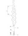
図1はこの発明の実施例1の家畜用人工授精カテーテルの正面図、図2は前記家畜用人工授精カテーテルを構成する子宮体内挿入用の外側パイプ1と先端部にノズル部2を有する可撓性のチューブ3の正面図、図3は前記外側パイプ1にチューブ3を挿入し、ノズル部2を有するチューブ3の先端側を外側パイプ1の先端から押し出した状態を示す正面図を示している。 FIG. 1 is a front view of a livestock artificial insemination catheter according to
(この家畜用人工授精カテーテルの構成について)
この家畜用人工授精カテーテルは豚用のものであり、図1に示すように、雌豚の子宮体内挿入用の外側パイプ1の内部に、先端部にノズル部2を有するチューブ3を押出し自在に挿入して成り、ノズル部2を有するチューブ3の先端側を外側パイプ1の先端から押し出した状態で、精液注入器4内の精液をチューブ3の後端部側からノズル部2に向かって送り出すようにするものである。(About the structure of this artificial insemination catheter for livestock)
This livestock artificial insemination catheter is for pigs, and, as shown in FIG. 1, a
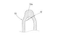
外側パイプ1は、図1〜図3に示すように、雄豚の性器を形どったウレタンゴム製(その他、シリコンゴム、軟質PVC製等)の疑似性器部10をパイプ部11に連通接続して構成してあり、前記疑似性器部10の先端部にパイプ長手方向に延びる切込12aを入れて予めチューブ3が押し出される口部12を形成してある。 As shown in FIGS. 1 to 3, the
疑似性器部10は、図1や図2に示すように先端先細の捩じれ形状となっており、上記口部12が開いたときには、図3に示す如く外側パイプ1と連通する両端開放のパイプ状となるようにしてある。なお、この疑似性器部10の口部12は、ノズル部2からの押圧力が作用していないときには図2に示す如く密閉した状態となり、ノズル部2からの押圧力が作用した場合にのみ図3に示す如く開口するようになっている。したがって、子宮体内挿入時において疑似性器部10の口部12からのカテーテル内への雑菌や異物の侵入を防止でき、且つ精液注入時には押圧力で確実に開口でき安全である。 As shown in FIGS. 1 and 2, the
パイプ部11は、テフロン(登録商標)やポリプロピレン等の半透明の樹脂により構成されており、先端に繋がれた疑似性器部10が子宮内の所定深さにまで至る長さに設定してある。 The
ノズル部2は、図2や図3に示すように、先端部が球面となった先端閉塞の筒形状のものであり、その周面には180°間隔で小孔20,20を形成してある。なお、このノズル部2は、図2や図3に示すように、後端部側の筒孔21と上記小孔20,20とが連通するようになっている。 As shown in FIG. 2 and FIG. 3, the
チューブ3は、上記パイプ部11の内径よりも小径に形成されて成る実質的に精液が通るところであり、その径はパイプ部11内における押し込み及び引き出しがスムーズで行い得るように設定してある。なお、このチューブ3はテフロン(登録商標)、PVC、オレフィン等の可撓性を有する半透明の中空ものとしてある。 The
精液注入器4は、図1に示すように、シリンダー40と押し棒41とから構成された所謂注射器形状のものであり、前記シリンダー40の先端側をチューブ3の後端部と連通接続してある。 As shown in FIG. 1, the semen injector 4 has a so-called syringe shape composed of a
この家畜用人工授精カテーテルは上記のように構成されているから、シリンダー40内に精液を貯留した状態において、押し棒41を押し込むと、精液は上記したチューブ3内を通ってノズル部2の小孔20,20から排出されることになる。なお、この家畜用人工授精カテーテルはこの種のものと同様の態様で使用されるので、その説明は省略する。 Since this livestock artificial insemination catheter is configured as described above, when the
(この家畜用人工授精カテーテルの優れた点について)
この家畜用人工授精カテーテルでは、雌豚の膣内に疑似性器部10が奥になるように挿入し、外側パイプ1に挿入されているノズル部2を有するチューブ3が疑似性器部10の先端から押し出されることとなるが、この際、予め形成されている口部12がノズル部2により押圧されて開かれる態様で送り出されることになるので、従来のもののように雌豚の膣内や子宮内に外側パイプ1の疑似性器部10から離脱した先端部分が残留することがない。(About the excellent point of this artificial insemination catheter for livestock)
In this livestock artificial insemination catheter, the pseudo
また、上記したように、ノズル部2を有するチューブ3は予め形成されている口部12がノズル部2により押圧されて開かれる態様で送り出されるようになっているから、家畜の子宮体内挿入用の外側パイプ1に対してチューブ3の送り出しが確実にできる。 Further, as described above, the
この実施例2の家畜用人工授精カテーテルは、上記した実施例1とほぼ同様の構成であるが、疑似性器部10の口部12を形成するための切込み位置及び方向が相違している。 The artificial insemination catheter for livestock of Example 2 has substantially the same configuration as that of Example 1 described above, but the cutting position and direction for forming the
つまり、この実施例2の家畜用人工授精カテーテルでは、図4に示すように口部12は周面から長さ方向と直交する方向に切込み12aを入れるようにして形成している。 That is, in the livestock artificial insemination catheter of Example 2, as shown in FIG. 4, the
この実施例3の家畜用人工授精カテーテルは、上記した実施例1とほぼ同様の構成であるが、疑似性器部10の口部12を形成するための切込み位置及び方向が相違している。 The artificial insemination catheter for livestock of Example 3 has substantially the same configuration as that of Example 1 described above, but the cutting position and direction for forming the
つまり、この実施例3の家畜用人工授精カテーテルでは、図5に示すように、口部12は周面から長さ方向に対して角度を付けて斜めに切込み12aを入れるようにして形成している。 That is, in the livestock artificial insemination catheter of Example 3, as shown in FIG. 5, the
(その他)
上記実施例のノズル部の形態に変えて、ノズル部2に設けた小孔20を先端に1つのみ設けるようにしてもよいし、更には、図6に示すように、ノズル部2とチューブ3とを一体成形する形態を採ることもできる。(Other)
Instead of the form of the nozzle part of the above embodiment, only one
上記実施例では、家畜の子宮内に雄豚の精子を送り出すようにしているが、これに変えて卵子(授精卵)を送り出すようにしてもよい。 In the above embodiment, boar sperm is sent out into the womb of livestock, but instead of this, an ovum (fertilized egg) may be sent out.
1 外側パイプ
2 ノズル部
3 チューブ
4 精液注入器
10 疑似性器部
11 パイプ部
12 口部
12a 切込み
20 小孔DESCRIPTION OF
Claims (3)
Translated fromJapanesePriority Applications (1)
| Application Number | Priority Date | Filing Date | Title |
|---|---|---|---|
| JP2004019430AJP2005211190A (en) | 2004-01-28 | 2004-01-28 | Catheter for artificial insemination for livestock |
Applications Claiming Priority (1)
| Application Number | Priority Date | Filing Date | Title |
|---|---|---|---|
| JP2004019430AJP2005211190A (en) | 2004-01-28 | 2004-01-28 | Catheter for artificial insemination for livestock |
Publications (1)
| Publication Number | Publication Date |
|---|---|
| JP2005211190Atrue JP2005211190A (en) | 2005-08-11 |
Family
ID=34903644
Family Applications (1)
| Application Number | Title | Priority Date | Filing Date |
|---|---|---|---|
| JP2004019430APendingJP2005211190A (en) | 2004-01-28 | 2004-01-28 | Catheter for artificial insemination for livestock |
Country Status (1)
| Country | Link |
|---|---|
| JP (1) | JP2005211190A (en) |
Cited By (4)
| Publication number | Priority date | Publication date | Assignee | Title |
|---|---|---|---|---|
| JP2008206881A (en)* | 2007-02-28 | 2008-09-11 | National Agriculture & Food Research Organization | Equipment for deep uterine injection of livestock |
| JP2010012247A (en)* | 2008-06-30 | 2010-01-21 | Imv Technologies | Instrument for intra-uterine transfer by natural vagino-uterine route |
| WO2018225886A1 (en)* | 2017-06-09 | 2018-12-13 | 이순용 | Sperm injector for artificial insemination of pig |
| JP2020185399A (en)* | 2014-10-28 | 2020-11-19 | アイエムブイ テクノロジーズ | Working assembly with observation system in particular for specifying cervix |
- 2004
- 2004-01-28JPJP2004019430Apatent/JP2005211190A/enactivePending
Cited By (4)
| Publication number | Priority date | Publication date | Assignee | Title |
|---|---|---|---|---|
| JP2008206881A (en)* | 2007-02-28 | 2008-09-11 | National Agriculture & Food Research Organization | Equipment for deep uterine injection of livestock |
| JP2010012247A (en)* | 2008-06-30 | 2010-01-21 | Imv Technologies | Instrument for intra-uterine transfer by natural vagino-uterine route |
| JP2020185399A (en)* | 2014-10-28 | 2020-11-19 | アイエムブイ テクノロジーズ | Working assembly with observation system in particular for specifying cervix |
| WO2018225886A1 (en)* | 2017-06-09 | 2018-12-13 | 이순용 | Sperm injector for artificial insemination of pig |
Similar Documents
| Publication | Publication Date | Title |
|---|---|---|
| US5674178A (en) | Artificial insemination tool | |
| US6527703B2 (en) | Device for sow-intra-uterine insemination and embryo transfer | |
| US6860235B2 (en) | Apparatus for creating a pathway in an animal and methods therefor | |
| US6526917B1 (en) | Method and apparatus for creating a pathway in an animal | |
| EP0957797A1 (en) | A system for introducing a fluid into the uterus of an animal | |
| ES2222034T3 (en) | DEVICE FOR THE INSEMINATION OF ANIMALS, IN PARTICULAR, PIGS. | |
| CA2490727C (en) | Apparatus for creating a pathway in an animal and methods therefor | |
| US5656010A (en) | System for effecting embryo transplant | |
| US7971553B2 (en) | Method and apparatus for creating a pathway in an animal | |
| JP2005211190A (en) | Catheter for artificial insemination for livestock | |
| JP2008206881A (en) | Equipment for deep uterine injection of livestock | |
| US20120136204A1 (en) | Enhanced device for the artificial insemination of sheep, goats, deer and/or domestic and wild animals | |
| JP2001120581A (en) | Instrument and method for transplant of animal embryo | |
| JP4769913B2 (en) | Deep injector for transplantation of livestock embryos | |
| JP3115795U (en) | Vaginal artificial insemination equipment for canines | |
| JP2884060B2 (en) | Livestock conception syringe cover | |
| BR112021003722A2 (en) | devices and methods for artificial insemination. | |
| US11103336B2 (en) | Animal insemination and in-vitro fertilization sheath, cap and methods of use | |
| HK1078738B (en) | Apparatus for creating a pathway in an animal and methods therefor |