JP2005203549A - Optical fiber and its manufacturing method - Google Patents
Optical fiber and its manufacturing methodDownload PDFInfo
- Publication number
- JP2005203549A JP2005203549AJP2004008032AJP2004008032AJP2005203549AJP 2005203549 AJP2005203549 AJP 2005203549AJP 2004008032 AJP2004008032 AJP 2004008032AJP 2004008032 AJP2004008032 AJP 2004008032AJP 2005203549 AJP2005203549 AJP 2005203549A
- Authority
- JP
- Japan
- Prior art keywords
- optical fiber
- longitudinal direction
- core
- refractive index
- core member
- Prior art date
- Legal status (The legal status is an assumption and is not a legal conclusion. Google has not performed a legal analysis and makes no representation as to the accuracy of the status listed.)
- Granted
Links
- 239000013307optical fiberSubstances0.000titleclaimsabstractdescription138
- 238000004519manufacturing processMethods0.000titleclaimsdescription26
- 230000005284excitationEffects0.000claimsdescription88
- 238000005253claddingMethods0.000claimsdescription53
- 239000012700ceramic precursorSubstances0.000claimsdescription19
- 238000005086pumpingMethods0.000claimsdescription16
- 239000013543active substanceSubstances0.000claimsdescription6
- 230000009969flowable effectEffects0.000claimsdescription2
- 239000000835fiberSubstances0.000abstractdescription25
- 230000010355oscillationEffects0.000abstractdescription14
- 239000011149active materialSubstances0.000abstractdescription3
- 238000000034methodMethods0.000description10
- 230000002093peripheral effectEffects0.000description6
- 239000011248coating agentSubstances0.000description5
- 238000000576coating methodMethods0.000description3
- 229910052761rare earth metalInorganic materials0.000description3
- 229910052691ErbiumInorganic materials0.000description2
- 229910052779NeodymiumInorganic materials0.000description2
- 238000010304firingMethods0.000description2
- 239000011521glassSubstances0.000description2
- 230000003287optical effectEffects0.000description2
- 229920001709polysilazanePolymers0.000description2
- 239000004065semiconductorSubstances0.000description2
- 238000007792additionMethods0.000description1
- 230000005540biological transmissionEffects0.000description1
- 238000012217deletionMethods0.000description1
- 230000037430deletionEffects0.000description1
- 230000000694effectsEffects0.000description1
- 238000000605extractionMethods0.000description1
- 229910052751metalInorganic materials0.000description1
- 239000002184metalSubstances0.000description1
- 238000012986modificationMethods0.000description1
- 230000004048modificationEffects0.000description1
- 238000003466weldingMethods0.000description1
Images


Classifications
- C—CHEMISTRY; METALLURGY
- C03—GLASS; MINERAL OR SLAG WOOL
- C03B—MANUFACTURE, SHAPING, OR SUPPLEMENTARY PROCESSES
- C03B37/00—Manufacture or treatment of flakes, fibres, or filaments from softened glass, minerals, or slags
- C03B37/01—Manufacture of glass fibres or filaments
- C03B37/012—Manufacture of preforms for drawing fibres or filaments
- C03B37/01205—Manufacture of preforms for drawing fibres or filaments starting from tubes, rods, fibres or filaments
- C03B37/01211—Manufacture of preforms for drawing fibres or filaments starting from tubes, rods, fibres or filaments by inserting one or more rods or tubes into a tube
- C03B37/01222—Manufacture of preforms for drawing fibres or filaments starting from tubes, rods, fibres or filaments by inserting one or more rods or tubes into a tube for making preforms of multiple core optical fibres
- C—CHEMISTRY; METALLURGY
- C03—GLASS; MINERAL OR SLAG WOOL
- C03B—MANUFACTURE, SHAPING, OR SUPPLEMENTARY PROCESSES
- C03B37/00—Manufacture or treatment of flakes, fibres, or filaments from softened glass, minerals, or slags
- C03B37/01—Manufacture of glass fibres or filaments
- C03B37/012—Manufacture of preforms for drawing fibres or filaments
- C03B37/01205—Manufacture of preforms for drawing fibres or filaments starting from tubes, rods, fibres or filaments
- G—PHYSICS
- G02—OPTICS
- G02B—OPTICAL ELEMENTS, SYSTEMS OR APPARATUS
- G02B6/00—Light guides; Structural details of arrangements comprising light guides and other optical elements, e.g. couplings
- G02B6/02—Optical fibres with cladding with or without a coating
- G02B6/02042—Multicore optical fibres
- G—PHYSICS
- G02—OPTICS
- G02B—OPTICAL ELEMENTS, SYSTEMS OR APPARATUS
- G02B6/00—Light guides; Structural details of arrangements comprising light guides and other optical elements, e.g. couplings
- G02B6/24—Coupling light guides
- G02B6/42—Coupling light guides with opto-electronic elements
- G02B6/4201—Packages, e.g. shape, construction, internal or external details
- G02B6/4202—Packages, e.g. shape, construction, internal or external details for coupling an active element with fibres without intermediate optical elements, e.g. fibres with plane ends, fibres with shaped ends, bundles
- G02B6/4203—Optical features
- C—CHEMISTRY; METALLURGY
- C03—GLASS; MINERAL OR SLAG WOOL
- C03B—MANUFACTURE, SHAPING, OR SUPPLEMENTARY PROCESSES
- C03B2203/00—Fibre product details, e.g. structure, shape
- C03B2203/10—Internal structure or shape details
- C—CHEMISTRY; METALLURGY
- C03—GLASS; MINERAL OR SLAG WOOL
- C03B—MANUFACTURE, SHAPING, OR SUPPLEMENTARY PROCESSES
- C03B2203/00—Fibre product details, e.g. structure, shape
- C03B2203/10—Internal structure or shape details
- C03B2203/12—Non-circular or non-elliptical cross-section, e.g. planar core
- C—CHEMISTRY; METALLURGY
- C03—GLASS; MINERAL OR SLAG WOOL
- C03B—MANUFACTURE, SHAPING, OR SUPPLEMENTARY PROCESSES
- C03B2203/00—Fibre product details, e.g. structure, shape
- C03B2203/34—Plural core other than bundles, e.g. double core
Landscapes
- Chemical & Material Sciences (AREA)
- Engineering & Computer Science (AREA)
- Physics & Mathematics (AREA)
- Materials Engineering (AREA)
- Manufacturing & Machinery (AREA)
- Geochemistry & Mineralogy (AREA)
- Life Sciences & Earth Sciences (AREA)
- Organic Chemistry (AREA)
- General Life Sciences & Earth Sciences (AREA)
- General Physics & Mathematics (AREA)
- Optics & Photonics (AREA)
- Lasers (AREA)
- Optical Fibers, Optical Fiber Cores, And Optical Fiber Bundles (AREA)
Abstract
Description
Translated fromJapanese本発明は、レーザ活性物質を含むコア部材と、励起光を透過させるクラッド部材とを有するファイバレーザ発振に用いる光ファイバに関する。 The present invention relates to an optical fiber used for fiber laser oscillation having a core member containing a laser active substance and a cladding member that transmits excitation light.
従来より、比較的ビーム品質の劣る励起光を用いて非常に高品質のレーザ光を高効率で得ることができるファイバレーザ発振装置や、高速・大容量・長距離伝送が可能な光増幅器等に用いる種々の光ファイバが提案されている。
ファイバレーザに用いられる光ファイバは通常、断面の中心にコア部材(シングルモードのレーザ光を透過させ、希土類元素(Nd、Er)等がドープされた直径2〜12[μm]程度のファイバ形状)を有している。そして、コア部材の周囲に、コア部材よりも低い屈折率を持つクラッド部材(第1クラッド部材であり、励起光を透過させる)を有することで、レーザ光をコア部材内に閉じ込めている。更に第1クラッド部材の周囲に、第1クラッド部材の屈折率よりも低い屈折率を持つ第2クラッド部材を有することで、励起光を第1クラッド部材内に閉じ込めている。
そして、この光ファイバに入射された励起光がコア部材を通ると(コア部材に衝突すると)コア部材内の希土類元素が励起されてレーザ光が発生し、コア部材内にはシングルモードのレーザ光が残る。このレーザ光は、小径(コア部材の径に依存する)であり、かつ広がり角が小さい(発生したレーザ光の波長、コア部材及び第1クラッド部材の屈折率等に依存する)ため、ビーム品質が非常によい(レーザ光のビーム品質は、出射光の半径と、出射光の広がり角の半角との積で表され、この積が小さい程ビーム品質が高い)。Conventionally, for fiber laser oscillators that can obtain very high-quality laser light with high efficiency using pump light with relatively poor beam quality, optical amplifiers that can perform high-speed, large-capacity, and long-distance transmission Various optical fibers to be used have been proposed.
An optical fiber used for a fiber laser is usually a core member at the center of a cross section (a fiber shape with a diameter of about 2 to 12 [μm] doped with rare earth elements (Nd, Er) and the like that transmits single mode laser light). have. The laser beam is confined in the core member by having a clad member having a lower refractive index than the core member (a first clad member that transmits the excitation light) around the core member. Further, the second cladding member having a refractive index lower than that of the first cladding member is provided around the first cladding member, so that the excitation light is confined in the first cladding member.
When the excitation light incident on the optical fiber passes through the core member (when it collides with the core member), the rare earth element in the core member is excited to generate laser light, and single-mode laser light is generated in the core member. Remains. Since this laser beam has a small diameter (depending on the diameter of the core member) and a small divergence angle (depends on the wavelength of the generated laser beam, the refractive index of the core member and the first cladding member, etc.), the beam quality (The beam quality of the laser light is expressed by the product of the radius of the emitted light and the half angle of the spread angle of the emitted light, and the smaller the product, the higher the beam quality).
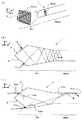
従来の一般的な光ファイバ1a(ファイバレーザ発振に用いる光ファイバ)は、図8(A)に示すように、円柱形状の第1クラッド部材10の長手方向(図8(A)のZ軸方向)に、レーザ活性物質を含むコア部材30が配置されている。また、図8(B)は、光ファイバ1aの長手方向に垂直な断面(図8(A)の断面BB)を示している。図8(B)に示すように、従来の一般的な光ファイバ1aは、長手方向に垂直な断面において、第1クラッド部材10の中心部分にコア部材30が配置されている。
この光ファイバ1aの長手方向に垂直な端面から励起光Linを入射すると、入射した励起光Linが第1クラッド部材10内を全反射しながら進行する。そして、第1クラッド部材10内を全反射しながら進行する励起光Linが(偶然的に)コア部材30に衝突すると、コア部材30内でレーザ光が励起される。A conventional general optical fiber 1a (an optical fiber used for fiber laser oscillation) is, as shown in FIG. 8A, the longitudinal direction of a cylindrical first cladding member 10 (Z-axis direction in FIG. 8A). ), The
When the excitation light Lin is incident from the end face perpendicular to the longitudinal direction of the optical fiber 1a, the incident excitation light Lin proceeds while being totally reflected in the
なお、一般的な光ファイバ1aでは、より高品質なレーザ光を得るためにコア部材30の径を約2〜12[μm]としており、より高出力のレーザ光を得る目的でより多くの励起光を入射するために第1クラッド部材10の径を約100[μm]としている。従って、第1クラッド部材10の断面積に対するコア部材30の断面積が非常に小さい。このため、図8(B)に示すように、励起光Linがコア部材30に衝突することなく、第1クラッド部材10内で全反射しながら第1クラッド部材10の外周に沿って周回してしまう場合がある。また、図8(C)に示すように、周回してしまう励起光Linをより低減するために第1クラッド部材10の断面形状を矩形にした光ファイバも提案されているが、それでも周回してしまう励起光Linが発生する場合がある。
また、励起光Linは、比較的ビーム品質が劣るので、コア部材30に衝突するように狙って入射することは非常に困難である。In the general optical fiber 1a, the diameter of the
Further, since the excitation light Lin has a relatively poor beam quality, it is very difficult to aim the light so as to collide with the
そこで、例えばファイバレーザ発振装置の分野では、円筒形のガラス円柱体の外周面にコア部材を巻回し、円柱体の端面の外周端部近傍からプリズムを用いて励起光を入射し、励起光を円柱体の内部で全反射させながら螺旋状に周回させ、レーザ出力をより向上させるファイバレーザ発振装置が提案されている(例えば特許文献1参照)。
また、例えば光増幅器の分野では、図8(D)〜(G)に示すように、光ファイバの第1クラッド部材10内にコア部材30を少なくとも3本有し、長手方向に少なくとも2個所のモードフィールド径の変化した領域23を設け、利得が低いときだけでなく、利得が高いときであっても、利得波長特性を平坦にすることができる、マルチコアファイバ1bが提案されている(例えば特許文献2参照)。
Further, for example, in the field of optical amplifiers, as shown in FIGS. 8D to 8G, the first
特許文献1に記載のファイバレーザ発振装置では、円柱体の外周面に剥き出しのコア部材を巻きつけるため、コア部材が折れ易いと推定される。
また、特許文献1に記載のファイバレーザ発振装置では、プリズムを用いて励起光を入射し、円柱体の外周面を周回するように励起光を入射する必要があるため、より多くの励起光を入射しようとした場合、入射した励起光を全て周回させることは非常に困難である(例えば励起光の径を大きくすると、円柱体の外周面への入射角が円柱体の内部で全反射するための角度を満足しない励起光が多くなる可能性がある)。
また、特許文献2に記載のマルチコアファイバ1bでは、コア部材30を複数有しているが、図8(E)〜(G)に示すように、当該コア部材30が断面のほぼ中心に配置されているため、第1クラッド部材10の外周に沿って周回するような励起光が衝突する確率は低いと推定される。
本発明は、このような点に鑑みて創案されたものであり、ファイバレーザ発振において、より多くの励起光がコア部材を励起することができ、より効率よくレーザ光を得ることができる光ファイバを提供することを課題とする。In the fiber laser oscillation device described in
Further, in the fiber laser oscillation device described in
Moreover, although the multi-core fiber 1b described in
The present invention was devised in view of such points, and in fiber laser oscillation, an optical fiber that can excite a core member with more pumping light and can obtain laser light more efficiently. It is an issue to provide.
上記課題を解決するための手段として、本発明の第1発明は、請求項1に記載されたとおりの光ファイバである。
請求項1に記載の光ファイバは、レーザ活性物質を含むコア部材を長手方向に有するとともに当該コア部材の少なくとも一部をクラッド部材で覆った光ファイバであって、複数のコア部材が光ファイバの長手方向に配置されているとともに、当該複数のコア部材が、光ファイバの長手方向に垂直な断面において、クラッド部材の縁部に配置されている。As means for solving the above-mentioned problems, a first invention of the present invention is an optical fiber as defined in
The optical fiber according to
また、本発明の第2発明は、請求項2に記載されたとおりの光ファイバである。
請求項2に記載の光ファイバは、請求項1に記載の光ファイバであって、コア部材は1本であり、当該コア部材が光ファイバの長手方向に複数回往復するように配置されている。The second invention of the present invention is an optical fiber as defined in
An optical fiber according to a second aspect is the optical fiber according to the first aspect, wherein the number of the core member is one, and the core member is arranged to reciprocate a plurality of times in the longitudinal direction of the optical fiber. .
また、本発明の第3発明は、請求項3に記載されたとおりの光ファイバの製造方法である。
請求項3に記載の光ファイバの製造方法は、光ファイバの長手方向に垂直な断面において、クラッド部材の縁部に複数のコア部材が配置されている光ファイバの製造方法であって、クラッド部材の外周上に、且つ長手方向にコア部材を並べ、クラッド部材が流動可能状態になるまで加熱して、コア部材をクラッド部材に押し付ける方法である。The third invention of the present invention is a method for manufacturing an optical fiber as defined in
The optical fiber manufacturing method according to
また、本発明の第4発明は、請求項4に記載されたとおりの光ファイバの製造方法である。
請求項4に記載の光ファイバの製造方法は、光ファイバの長手方向に垂直な断面において、クラッド部材の縁部に複数のコア部材が配置されている光ファイバの製造方法であって、クラッド部材の外周上に、且つ長手方向にコア部材を並べ、クラッド部材と同等の屈折率を有するセラミックス前駆体あるいは、クラッド部材の屈折率以上且つコア部材の屈折率未満の屈折率を有するセラミックス前駆体にて、前記外周上にコア部材を並べたクラッド部材の外周を覆う方法である。According to a fourth aspect of the present invention, there is provided an optical fiber manufacturing method as set forth in the fourth aspect.
The optical fiber manufacturing method according to
また、本発明の第5発明は、請求項5に記載されたとおりの光ファイバの製造方法である。
請求項5に記載の光ファイバの製造方法は、請求項3または4に記載した光ファイバの製造方法にて製造した光ファイバを、クラッド部材よりも低い屈折率を有する中空部材に挿入し、光ファイバ及び中空部材との間隙を、クラッド部材と同等の屈折率を有するセラミックス前駆体あるいは、クラッド部材の屈折率以上且つコア部材の屈折率未満の屈折率を有するセラミックス前駆体で充填する方法である。The fifth invention of the present invention is a method for manufacturing an optical fiber as described in
According to a fifth aspect of the present invention, there is provided an optical fiber manufacturing method in which an optical fiber manufactured by the optical fiber manufacturing method according to the third or fourth aspect is inserted into a hollow member having a refractive index lower than that of a cladding member. In this method, the gap between the fiber and the hollow member is filled with a ceramic precursor having a refractive index equivalent to that of the clad member or a ceramic precursor having a refractive index greater than that of the clad member and less than that of the core member. .
また、本発明の第6発明は、請求項6に記載されたとおりの光ファイバである。
請求項6に記載の光ファイバは、レーザ活性物質を含むコア部材を長手方向に有するとともに当該コア部材の少なくとも一部をクラッド部材で覆った光ファイバであって、励起光を入射する少なくとも1つの端面が、長手方向に垂直な断面に対して所定の角度を有する斜めの面(平面または曲面)に形成されている。According to a sixth aspect of the present invention, there is provided an optical fiber as set forth in the sixth aspect.
The optical fiber according to
また、本発明の第7発明は、請求項7に記載されたとおりの光ファイバである。
請求項7に記載の光ファイバは、請求項6に記載の光ファイバであって、更に、励起光を入射する少なくとも1つの端面において、長手方向に垂直な断面に対して所定の角度を有する斜めの面(平面または曲面)を複数形成し、当該端面が多角錐状に形成されている。The seventh invention of the present invention is an optical fiber as set forth in
An optical fiber according to a seventh aspect is the optical fiber according to the sixth aspect, wherein at least one end face on which the excitation light is incident has an oblique angle with a predetermined angle with respect to a cross section perpendicular to the longitudinal direction. A plurality of surfaces (plane or curved surface) are formed, and the end surfaces are formed in a polygonal pyramid shape.
また、本発明の第8発明は、請求項8に記載されたとおりの光ファイバである。
請求項8に記載の光ファイバは、請求項6または7に記載の光ファイバであって、光ファイバは、励起光を入射する励起光入射部と、入射された励起光が全反射しながらコア部材を励起する励起部とで構成され、励起部における長手方向に垂直な断面の断面積よりも、励起光入射部の一部における長手方向に垂直な断面の断面積の方が大きくなるように構成されている。An eighth invention of the present invention is an optical fiber as set forth in the eighth aspect.
An optical fiber according to an eighth aspect is the optical fiber according to the sixth or seventh aspect, wherein the optical fiber includes a pumping light incident part for entering the pumping light and a core while the incident pumping light is totally reflected. The excitation section that excites the member, and the sectional area of the section perpendicular to the longitudinal direction in the excitation section is larger than the sectional area of the excitation light incident section in the section perpendicular to the longitudinal direction. It is configured.
請求項1に記載の光ファイバでは、複数のコア部材がクラッド部材の縁部に配置されているので、クラッド部材の外周部で全反射する励起光が周回するように全反射しても、より高い確率で励起光をコア部材に衝突させることができる。
このため、より多くの励起光がコア部材を励起することができ、より効率よくレーザ光を得ることができる。In the optical fiber according to
For this reason, more excitation light can excite the core member, and laser light can be obtained more efficiently.
また、請求項2に記載の光ファイバでは、1本のコア部材を長手方向に往復させて配置することで、複数のコア部材がクラッド部材の縁部に配置されるように構成する。
このため、励起されたレーザ光は、1本のコア部材の内部で発生する。そして、当該1本のコア部材の出力端からレーザ光を取り出す際、取り出し口が1本であるので、より小径の、より高品質のレーザ光を得ることができる。The optical fiber according to
For this reason, the excited laser light is generated inside one core member. And when taking out a laser beam from the output end of the said one core member, since there is one taking-out port, a smaller diameter and a higher quality laser beam can be obtained.
また、請求項3〜5のいずれかに記載の光ファイバの製造方法によれば、請求項1または2に記載の光ファイバを、より容易に製造することが可能である。 Moreover, according to the manufacturing method of the optical fiber in any one of Claims 3-5, it is possible to manufacture the optical fiber of
また、請求項6に記載の光ファイバでは、励起光を入射する端面を、長手方向に垂直でなく、所定の角度を有するように斜めの面(平面または曲面)に形成することで、励起光の入射面の面積を、より大きくすることができる。
これにより、より大きな入射面からより多くの励起光を入射することができ、より多くの励起光がコア部材を励起することができる。In the optical fiber according to
Thereby, more excitation light can be incident from a larger incident surface, and more excitation light can excite the core member.
また、請求項7に記載の光ファイバでは、励起光を入射する端面を多角錐状に形成することで、励起光の入射面の面積をより大きくするとともに、当該多角錐の各面の方向に励起光の入射装置を配置することができる。
これにより、複数の方向からより多くの励起光を入射することができ、より多くの励起光がコア部材を励起することができる。In the optical fiber according to
Thereby, more excitation light can be incident from a plurality of directions, and more excitation light can excite the core member.
また、請求項8に記載の光ファイバは、励起光入射部の面積(長手方向に垂直な断面積)が最も大きくなる部分が、光ファイバの励起部(励起光入射部を除いた部分)の面積(長手方向に垂直な断面積)よりも大きくなるように設定し、更に励起光を入射する面を更に大きくする。
これにより、更に多くの励起光がコア部材を励起することができる。Further, in the optical fiber according to the eighth aspect, the portion where the area (cross-sectional area perpendicular to the longitudinal direction) of the pumping light incident portion is the largest is the pumping portion (portion excluding the pumping light incident portion) of the optical fiber. It is set to be larger than the area (cross-sectional area perpendicular to the longitudinal direction), and the surface on which the excitation light is incident is further increased.
Thereby, more excitation light can excite the core member.
以下に本発明を実施するための最良の形態を図面を用いて説明する。図1は本発明の光ファイバ1の概略図を示している。
●[光ファイバの構造(図1)]
図1(A)は、本実施の形態の光ファイバ1における、長手方向(図1におけるZ軸方向)に垂直な断面図の例を示している。光ファイバ1は、コア部材30を長手方向に有しており、コア部材30にはレーザ活性物質(希土類元素であるNd、Er等)がドープされている。また、コア部材30の少なくとも一部はクラッド部材10(以下、クラッド部材10を「第1クラッド部材10」と記載する)で覆われている。また、図1に示す例では、第1クラッド部材10の外周を更に第2クラッド部材20で覆っている。
また、各部材の屈折率の関係は、コア部材30の屈折率(n30)>第1クラッド部材10の屈折率(n10)>第2クラッド部材20の屈折率(n20)>空気の屈折率となるように設定されている。なお、第2クラッド部材20は省略してもよい。The best mode for carrying out the present invention will be described below with reference to the drawings. FIG. 1 shows a schematic view of an
● [Optical fiber structure (Figure 1)]
FIG. 1A shows an example of a cross-sectional view perpendicular to the longitudinal direction (Z-axis direction in FIG. 1) in the
Further, the refractive index relationship of each member is as follows: the refractive index of the core member 30 (n30)> the refractive index of the first cladding member 10 (n10)> the refractive index of the second cladding member 20 (n20)> the refractive index of air. It is set to be. Note that the
また、コア部材30が「少なくとも一部が第1クラッド部材10に覆われている」という概念は、図1(B)に示すように、長手方向に垂直な断面において、コア部材30が第1クラッド部材10の内部に配置されている場合を含むとともに、図1(C)に示すように、長手方向に垂直な断面において、コア部材30が第1クラッド部材10と第2クラッド部材20の境界に配置されている場合も含み、図1(D)に示すように、コア部材30が第1クラッド部材10の外周に接するように配置されている場合も含む。
そして、複数のコア部材30を光ファイバ1の長手方向に配置し、当該複数のコア部材30が、長手方向に垂直な断面において、第1クラッド部材10の縁部に配置されている(図1(A)〜(D)参照)。Further, the concept that the
Then, the plurality of
これにより、光ファイバ1の端面から入射された励起光(例えば半導体レーザ光)が第1クラッド部材10の外周部で全反射しながら進行しても、より確実に励起光をコア部材30に衝突させて、コア部材30のレーザ活性物質を励起して出力レーザ光を発生させることができる。
なお、光ファイバ1に配置する複数のコア部材30は、図1(E)に示すように複数本のコア部材30を配置して構成してもよいし、図1(F)及び(G)に示すように1本または複数のコア部材を、光ファイバ1の長手方向に複数回往復するように配置して構成するようにしてもよい。Thereby, even if the excitation light (for example, semiconductor laser light) incident from the end face of the
The plurality of
●[光ファイバを用いたファイバレーザ発振装置(図2)]
次に図2を用いて、上記に説明した光ファイバ1を用いたファイバレーザ発振装置の例を説明する。図2(B)は図2(A)における長手方向に垂直な断面BBを示しており、図2(C)は図2(A)における長手方向に垂直な断面CCを示している。
図2(A)の例では、光ファイバ1の左端面から励起光Linを入射し、右端面から出力レーザ光Loutを取り出している。なお、図2(A)の例では、光ファイバ1の右端面(出力レーザ光の取り出し側の端面)では、テーパ部Mtpにて光ファイバ1をテーパ形状に絞り、複数のコア部材30を束ねている。束ねることで、複数のコア部材30による径(長手方向に垂直な径であり、図2(C)のφbundleに相当する)を小さくすることができ、出力レーザ光Loutのビーム品質を、より向上させることができる。なお、図1(F)の例に示す光ファイバ1の場合は、出力レーザ光Loutが1個所から出力されるため、束ねる必要はない。また、図1(G)の例に示す光ファイバ1の場合は束ねることが好ましい。
なお、励起光Linがコア部材30を励起させる励起部Mfiberの長さは、励起光Linが全て励起に使用されるのに充分な長さを有する。また、図2(C)に示す断面では、第1クラッド部材10及び第2クラッド部材20を残した状態の図を示したが、断面CC部分では第1クラッド部材10が残らないようにしてもよいし、第2クラッド部材20が残らないようにしてもよい。テーパ部Mtpでは、第1クラッド部材10も第2クラッド部材20も特になくてもよい。● [Fiber laser oscillator using optical fiber (Fig. 2)]
Next, an example of a fiber laser oscillation device using the
In the example of FIG. 2A, the excitation light Lin is incident from the left end surface of the
The length of the excitation part Mfiber that excites the
光ファイバ1における励起光Linの入射側端面には、励起光Linを透過して出力レーザ光Loutを反射する(透過させない)ダイクロイックミラー46を配置している(この例では、入射端面(光ファイバ1の左端面)に当接させている)。なお、ダイクロイックミラー46の代わりに、励起光Linを透過して出力レーザ光Loutを反射するコーティングを施してもよい。また、ダイクロイックミラーの配置、コーティングの実施は、コア部材30の端面(この場合、光ファイバ1の左端面のコア部材30の部分)のみに行ってもよい。
また、光ファイバ1における出力レーザ光Loutを取り出す側の端面(図2(A)の例では、光ファイバ1の右端面)には、出力レーザ光Loutを平行光に変換するコリメートレンズ42と、平行光に変換した出力レーザ光Loutをより小さな径に集光する集光レンズ44とを配置している。このように集光した出力レーザ光Loutは、より高いビーム品質にて高い出力と精度を有しており、レーザ加工、レーザ溶接等、種々の用途に用いることが可能である。A
Further, a collimating
以上に説明したファイバレーザ発振装置に用いた光ファイバ1は、励起光Linを入射する端面の径(図2(B)中のφcladに相当する)を約3〜10[mm]と大きくできるので、励起光Linを入射し易く、より多くの励起光Linを入射することができる。
また、テーパ部Mtpにてコア部材30を束ねることで、従来のファイバレーザ用光ファイバ(図8(B)及び(C)に示すファイバレーザ用光ファイバ)を複数本束ねるよりも小径の出力レーザ光Loutを得ることができるので、ビーム品質をより高くすることができる。Since the
Further, by bundling the
●[光ファイバの製造方法1(図3)]
次に図3(A)〜(E)を用いて、図1に説明した光ファイバ1の製造方法の例を説明する。
まず、図3(A)に示すように、第1クラッド部材10を形成する。なお、図3の例では便宜上、第1クラッド部材10を矩形に形成したが、円柱形状または多角柱形状等に形成してもよい。
次に図3(B)に示すように、第1クラッド部材10の側面に複数のコア部材30を長手方向に平行に並べて乗せる。更に第1クラッド部材10が流動可能な状態になるまで加熱する。
そして図3(C)に示すように、コア部材30を第1クラッド部材10の方向に押し付ける(ホットプレスHP等で第1クラッド部材10内にコア部材30を押し込む)。● [Optical fiber manufacturing method 1 (Fig. 3)]
Next, an example of a method for manufacturing the
First, as shown in FIG. 3A, the first clad
Next, as shown in FIG. 3B, a plurality of
Then, as shown in FIG. 3C, the
上記の図3(B)〜(C)の工程を、第1クラッド部材10の外周に渡って行うことで、図3(D)に示す構造を得ることができる。
第2クラッド部材20を省略する場合は、図3(D)に示す状態の光ファイバ1を用いればよい。また、第2クラッド部材20を省略しない場合は、図3(D)に示す状態において、外周を更に溶液状のセラミックス前駆体(ポリシラザン等のコーティング剤)で覆い、焼成して第2クラッド部材20を形成する。このときに用いるセラミックス前駆体は、第1クラッド部材10の屈折率よりも小さな屈折率を有するものを用いる。
以上に説明した工程にて、複数のコア部材30が第1クラッド部材10の縁部に配置された光ファイバ1を実現することが可能である。By performing the steps of FIGS. 3B to 3C over the outer periphery of the first clad
When the second clad
Through the steps described above, it is possible to realize the
●[光ファイバの製造方法2(図4)]
次に図4(A)〜(D)を用いて、図1に説明した光ファイバ1の製造方法とは別の製造方法の例を説明する。
まず、図4(A)に示すように、第1クラッド部材10を形成する。なお、図4の例では便宜上、第1クラッド部材10を円柱形状に形成したが、矩形または多角柱形状等に形成してもよい。
次に図4(B)に示すように、第1クラッド部材10の側面に複数のコア部材30を長手方向に平行に並べる。
そして図4(C)に示すように、外周を更に溶液状のセラミックス前駆体(ポリシラザン等のコーティング剤)で覆い、焼成する。このときに用いるセラミックス前駆体は、第1クラッド部材10と同等の屈折率を有するセラミックス前駆体あるいは、第1クラッド部材10の屈折率以上且つコア部材30の屈折率未満の屈折率を有するものを用いる。これにより、焼成したセラミックス前駆体を図4(A)で用意した第1クラッド部材10と熱結合させ、図4(A)で用意した第1クラッド部材10と焼成したセラミックス前駆体とで、新たな第1クラッド部材10を構成するとともに、コア部材30を固着する。● [Optical fiber manufacturing method 2 (Fig. 4)]
Next, an example of a manufacturing method different from the manufacturing method of the
First, as shown in FIG. 4A, the
Next, as shown in FIG. 4B, a plurality of
Then, as shown in FIG. 4C, the outer periphery is further covered with a solution-like ceramic precursor (a coating agent such as polysilazane) and fired. The ceramic precursor used at this time is a ceramic precursor having a refractive index equivalent to that of the
第2クラッド部材20を省略する場合は、図4(C)に示す状態から焼成した光ファイバ1を用いればよい。また、第2クラッド部材20を省略しない場合は、図4(C)から焼成した光ファイバ1において、更に外周を溶液状のセラミックス前駆体(第1クラッド部材10の屈折率よりも小さな屈折率を有するセラミック前駆体)で覆い、焼成して第2クラッド部材20を形成する。
もしくは、第1クラッド部材10よりも低い屈折率の第2クラッド部材20(中空のガラス棒等の中空部材)を形成し、当該第2クラッド部材20の中空部に、図3(D)または図4(B)または図4(C)の状態の光ファイバを挿入する。そして、光ファイバと第2クラッド部材20との間隙を、第1クラッド部材10と同等の屈折率を有する溶液状のセラミックス前駆体あるいは、第1クラッド部材10の屈折率以上且つコア部材30の屈折率未満の屈折率を有する溶液状のセラミックス前駆体で充填し、焼成して光ファイバ1を形成する。
以上に説明した工程にて、複数のコア部材30が第1クラッド部材10の縁部に配置された光ファイバ1を実現することが可能である。When the second clad
Alternatively, a second clad member 20 (hollow member such as a hollow glass rod) having a lower refractive index than that of the first clad
Through the steps described above, it is possible to realize the
●[その他の例(図5〜図7)]
図1に示す光ファイバ1は、入射した励起光Linがより高い確率でコア部材30に衝突及び励起する構造の例を示しているが、図5〜図6に示す光ファイバ1は、より多くの励起光Linを入射することができる光ファイバ1の構造の例を示している。この場合、コア部材30は従来の光ファイバのように、中心に1本配置してもよいし、図1に示すように第1クラッド部材10の外周に複数本配置するようにすれば更に高い効率で出力レーザ光Loutを得ることができる。
なお、図5及び図6では説明のため、コア部材30の記載を省略している。● [Other examples (Figs. 5-7)]
The
In FIG. 5 and FIG. 6, the description of the
[励起光の入射面を斜めに形成した光ファイバの例(図5(A)及び(B))]
図5(A)及び(B)に示すように、励起光Linを入射する端面S(以下、「励起光入射端面S」と記載する)を、長手方向に垂直な断面に対して所定の角度(図5(B)中の角度θ)を有するように斜めの面に形成する。なお、本実施の形態では、励起光入射端面Sの形状を平面としているが、励起光入射端面Sの形状を曲面に形成してレンズ効果を持たせるようにしてもよい。
なお、この場合、入射する励起光Linの入射角(励起光入射端面Sの垂線と励起光Linとが成す角度)が大きくなると第1クラッド部材10内に入射されずに励起光入射端面Sの表面で反射してしまう励起光Linが増加し易いので、励起光Linの入射角は、できるだけ小さいほうが好ましい(図5(B)の例では入射角が0°の例を示している)。
また、この場合、第1クラッド部材10内を進行する励起光Linと、第1クラッド部材10の側面との成す角θhが大きくなり易いので、第1クラッド部材10の外周を、励起光Linを全反射する部材(ミラー等)で覆うようにしてもよい。[Example of optical fiber in which incident surface of excitation light is formed obliquely (FIGS. 5A and 5B)]
As shown in FIGS. 5A and 5B, an end surface S on which the excitation light Lin is incident (hereinafter referred to as “excitation light incident end surface S”) has a predetermined angle with respect to a cross section perpendicular to the longitudinal direction. (An angle θ in FIG. 5B) is formed on an oblique surface. In the present embodiment, the shape of the excitation light incident end surface S is a flat surface, but the shape of the excitation light incident end surface S may be formed as a curved surface to have a lens effect.
In this case, if the incident angle of the incident excitation light Lin (the angle formed by the perpendicular of the excitation light incident end surface S and the excitation light Lin) is increased, the incident light is not incident on the
In this case, since the angle θh formed between the excitation light Lin traveling in the
[励起光の入射面を多角錐状に形成した光ファイバの例(図5(C)及び(D))]
他の実施例として、図5(C)及び(D)に示すように、励起光入射端面Sを、多角錐状(図5(C)及び(D)の例では四角錐)に形成する。以下、図5(A)及び(B)との相違点について説明する。
この場合、励起光入射端面Sの面積が増大するだけでなく、励起光入射端面Sの各平面の法線の方向にそれぞれ励起光Linの入射手段(励起光Linの発生装置等)を配置することができるので、より多くの励起光Linを、より容易に入射することができる。[Example of optical fiber in which incident surface of excitation light is formed in polygonal pyramid shape (FIGS. 5C and 5D)]
As another embodiment, as shown in FIGS. 5C and 5D, the excitation light incident end face S is formed in a polygonal pyramid shape (a quadrangular pyramid in the examples of FIGS. 5C and 5D). Hereinafter, differences from FIGS. 5A and 5B will be described.
In this case, not only the area of the excitation light incident end face S increases, but also the excitation light Lin incident means (excitation apparatus for the excitation light Lin, etc.) are arranged in the normal direction of each plane of the excitation light incident end face S. Therefore, more excitation light Lin can be incident more easily.
[励起光の入射面の径をより大きくした光ファイバの例(図6(A)〜(C))]
更に他の実施例として、図6(A)〜(C)に示すように、光ファイバ1を励起光Linを入射する励起光入射部Minと、入射された励起光Linが全反射しながらコア部材30を励起する励起部Mfiberとに分けた場合、励起部Mfiberの長手方向に垂直な断面の面積Sfiberよりも、励起光入射部Minの一部における、長手方向に垂直な断面の面積Smaxの方が大きくなるように励起光入射部Minを構成する。
なお、励起光Linは、励起光入射端面Sに対して垂直(入射角は0°)に入射(図6(B)参照)してもよいし、励起部Mfiber内での反射角(図6(C)におけるθ7a、θ7c)が小さくなるような入射角(図6(C)におけるθ6a、θ6c)で入射するようにしてもよい。
以下、図5(A)〜(D)と同様であるので説明を省略する。[Example of optical fiber having larger diameter of incident surface of excitation light (FIGS. 6A to 6C)]
As still another embodiment, as shown in FIGS. 6A to 6C, an
The excitation light Lin may be incident on the excitation light incident end surface S perpendicularly (incident angle is 0 °) (see FIG. 6B), or the reflection angle in the excitation part Mfiber (FIG. 6). The light may be incident at an incident angle (θ6a, θ6c in FIG. 6C) such that θ7a, θ7c) in (C) becomes small.
The description below is omitted because it is the same as FIGS.
[その他の例におけるファイバレーザ発振装置(図7)]
次に、図5(A)及び(B)に示す光ファイバ1を用いたファイバレーザ発振装置について説明する。
図7(A)に示すファイバレーザ発振装置の例は、コア部材30が複数本の場合の例であり、図7(B)に示すファイバレーザ発振装置の例は、コア部材30が1本の場合の例である。図2(A)に示すファイバレーザ発振装置とはダイクロイックミラー46の取り付け方法が異なっている。以下、この相違点について説明する。[Fiber Laser Oscillator in Other Example (FIG. 7)]
Next, a fiber laser oscillation device using the
The example of the fiber laser oscillation device illustrated in FIG. 7A is an example in the case where there are a plurality of
図7(A)及び(B)に示す例では、1本のコア部材30の端面に1個のダイクロイックミラー46を設けており、励起光入射端面Sにはダイクロイックミラー46を設けていない。なお、ダイクロイックミラー46の代わりにコーティングを施してもよい。この場合、コア部材30の端面毎(励起光入射端面S側の端面毎)に、出力レーザ光Loutを反射する部材(ダイクロイックミラー46等)を、コア部材30の端面に、当該コア部材の長手方向と垂直になるように当接させて設ければよい。
なお、図7(A)の一点鎖線部分に示すように、励起光入射端面S側のコア部材30の端面を、連結するようにしてもよい(図7(A)中のC部分)。連結したコア部材30は端面を持たないので、出力レーザ光Loutを反射する部材を設ける必要がない。In the example shown in FIGS. 7A and 7B, one
7A, the end surface of the
本発明の光ファイバ1及びその製造方法は、本実施の形態で説明した形状、構成、構造、方法等に限定されず、本発明の要旨を変更しない範囲で種々の変更、追加、削除が可能である。
本実施の形態の説明に用いた数値は一例であり、この数値に限定されるものではない。
本実施の形態では、励起光Linに半導体レーザを用いたが、励起光には種々のものを用いることができる。The
The numerical values used in the description of the present embodiment are examples, and are not limited to these numerical values.
In this embodiment, a semiconductor laser is used as the excitation light Lin, but various types of excitation light can be used.
本発明の光ファイバ1は、レーザ加工装置等、レーザ光を用いた種々の装置に適用できる。 The
1 光ファイバ
10 第1クラッド部材
20 第2クラッド部材
30 コア部材
42 コリメートレンズ
44 集光レンズ
46 ダイクロイックミラー
Lin 励起光
Lout (出力)レーザ光
DESCRIPTION OF
Claims (8)
Translated fromJapanese複数のコア部材が光ファイバの長手方向に配置されているとともに、当該複数のコア部材が、光ファイバの長手方向に垂直な断面において、クラッド部材の縁部に配置されている、
ことを特徴とする光ファイバ。An optical fiber having a core member containing a laser active substance in the longitudinal direction and at least a part of the core member covered with a cladding member,
The plurality of core members are disposed in the longitudinal direction of the optical fiber, and the plurality of core members are disposed at the edge of the cladding member in a cross section perpendicular to the longitudinal direction of the optical fiber.
An optical fiber characterized by that.
コア部材は1本であり、当該コア部材が光ファイバの長手方向に複数回往復するように配置されている、
ことを特徴とする光ファイバ。The optical fiber according to claim 1,
The core member is one, and the core member is arranged so as to reciprocate a plurality of times in the longitudinal direction of the optical fiber.
An optical fiber characterized by that.
クラッド部材の外周上に、且つ長手方向にコア部材を並べ、
クラッド部材が流動可能状態になるまで加熱して、コア部材をクラッド部材に押し付ける、
ことを特徴とする光ファイバの製造方法。In the cross section perpendicular to the longitudinal direction of the optical fiber, a method for producing an optical fiber in which a plurality of core members are arranged at the edge of the cladding member,
Arrange the core members on the outer periphery of the cladding member in the longitudinal direction,
Heat until the clad member is in a flowable state, and press the core member against the clad member.
An optical fiber manufacturing method characterized by the above.
クラッド部材の外周上に、且つ長手方向にコア部材を並べ、
クラッド部材と同等の屈折率を有するセラミックス前駆体あるいは、クラッド部材の屈折率以上且つコア部材の屈折率未満の屈折率を有するセラミックス前駆体にて、前記外周上にコア部材を並べたクラッド部材の外周を覆う、
ことを特徴とする光ファイバの製造方法。In the cross section perpendicular to the longitudinal direction of the optical fiber, a method for producing an optical fiber in which a plurality of core members are arranged at the edge of the cladding member,
Arrange the core members on the outer periphery of the cladding member in the longitudinal direction,
A ceramic precursor having a refractive index equivalent to that of the clad member or a ceramic precursor having a refractive index greater than or equal to the refractive index of the clad member and less than the refractive index of the core member, Covering the outer periphery,
An optical fiber manufacturing method characterized by the above.
前記光ファイバ及び中空部材との間隙を、クラッド部材と同等の屈折率を有するセラミックス前駆体あるいは、クラッド部材の屈折率以上且つコア部材の屈折率未満の屈折率を有するセラミックス前駆体で充填する、
ことを特徴とする光ファイバの製造方法。Inserting the optical fiber manufactured by the optical fiber manufacturing method according to claim 3 or 4 into a hollow member having a refractive index lower than that of the cladding member,
The gap between the optical fiber and the hollow member is filled with a ceramic precursor having a refractive index equivalent to that of the cladding member, or a ceramic precursor having a refractive index that is greater than or equal to the refractive index of the cladding member and less than the refractive index of the core member.
An optical fiber manufacturing method characterized by the above.
励起光を入射する少なくとも1つの端面が、長手方向に垂直な断面に対して所定の角度を有する斜めの面に形成されている、
ことを特徴とする光ファイバ。An optical fiber having a core member containing a laser active substance in the longitudinal direction and at least a part of the core member covered with a cladding member,
At least one end surface on which the excitation light is incident is formed on an oblique surface having a predetermined angle with respect to a cross section perpendicular to the longitudinal direction;
An optical fiber characterized by that.
更に、励起光を入射する少なくとも1つの端面において、長手方向に垂直な断面に対して所定の角度を有する斜めの面を複数形成し、当該端面が多角錐状に形成されている、
ことを特徴とする光ファイバ。The optical fiber according to claim 6,
Furthermore, at least one end surface on which the excitation light is incident is formed with a plurality of oblique surfaces having a predetermined angle with respect to a cross section perpendicular to the longitudinal direction, and the end surfaces are formed in a polygonal pyramid shape.
An optical fiber characterized by that.
光ファイバは、励起光を入射する励起光入射部と、入射された励起光が全反射しながらコア部材を励起する励起部とで構成され、
励起部における長手方向に垂直な断面の断面積よりも、励起光入射部の一部における長手方向に垂直な断面の断面積の方が大きくなるように構成されている、
ことを特徴とする光ファイバ。
The optical fiber according to claim 6 or 7,
The optical fiber is composed of a pumping light incident part that enters the pumping light and a pumping part that pumps the core member while totally reflecting the incident pumping light,
It is configured such that the cross-sectional area of the cross section perpendicular to the longitudinal direction in a part of the excitation light incident part is larger than the cross-sectional area of the cross section perpendicular to the longitudinal direction in the excitation part.
An optical fiber characterized by that.
Priority Applications (2)
| Application Number | Priority Date | Filing Date | Title |
|---|---|---|---|
| JP2004008032AJP3889746B2 (en) | 2004-01-15 | 2004-01-15 | Optical fiber manufacturing method |
| PCT/JP2004/018856WO2005069453A1 (en) | 2004-01-15 | 2004-12-10 | Optical fiber and method for manufacturing same |
Applications Claiming Priority (1)
| Application Number | Priority Date | Filing Date | Title |
|---|---|---|---|
| JP2004008032AJP3889746B2 (en) | 2004-01-15 | 2004-01-15 | Optical fiber manufacturing method |
Publications (2)
| Publication Number | Publication Date |
|---|---|
| JP2005203549Atrue JP2005203549A (en) | 2005-07-28 |
| JP3889746B2 JP3889746B2 (en) | 2007-03-07 |
Family
ID=34792207
Family Applications (1)
| Application Number | Title | Priority Date | Filing Date |
|---|---|---|---|
| JP2004008032AExpired - Fee RelatedJP3889746B2 (en) | 2004-01-15 | 2004-01-15 | Optical fiber manufacturing method |
Country Status (2)
| Country | Link |
|---|---|
| JP (1) | JP3889746B2 (en) |
| WO (1) | WO2005069453A1 (en) |
Cited By (9)
| Publication number | Priority date | Publication date | Assignee | Title |
|---|---|---|---|---|
| CN101840022A (en)* | 2010-04-02 | 2010-09-22 | 哈尔滨工程大学 | Ring-shaped distributed multi-core fiber and preparation method thereof |
| JP2010286534A (en)* | 2009-06-09 | 2010-12-24 | Mitsubishi Cable Ind Ltd | Optical fiber coupling structure and method of manufacturing the same |
| JP2014099453A (en)* | 2012-11-13 | 2014-05-29 | Sumitomo Electric Ind Ltd | Amplifying multi-core optical fiber and multi-core optical fiber amplifier |
| JP2014135508A (en)* | 2010-03-16 | 2014-07-24 | Ofs Fitel Llc | Multi-core fiber for transmission and amplification, and mechanism for emitting pump light to amplifier core |
| WO2014132990A1 (en)* | 2013-02-26 | 2014-09-04 | 古河電気工業株式会社 | Optical-fiber-bundle structure, rare-earth-doped multi-core fiber, connection structure therefor, method for exciting rare-earth-doped multi-core fibers, and multi-core-optical-fiber amplifier |
| JP2014197193A (en)* | 2013-03-15 | 2014-10-16 | オーエフエス ファイテル,エルエルシー | Ring combiner |
| JP2014236210A (en)* | 2013-06-05 | 2014-12-15 | 日本電信電話株式会社 | Multi-core optical transmission system, optical amplifier and component for optical amplification |
| EP2919334A4 (en)* | 2012-11-07 | 2016-07-27 | Fujikura Ltd | OPTICAL FIBER AMPLIFIER AND OPTICAL AMPLIFIER |
| EP2919335B1 (en)* | 2012-11-07 | 2018-03-07 | Fujikura Ltd. | Amplifying optical fiber and optical amplifier |
Families Citing this family (2)
| Publication number | Priority date | Publication date | Assignee | Title |
|---|---|---|---|---|
| JP2006261194A (en)* | 2005-03-15 | 2006-09-28 | Jtekt Corp | Fiber laser oscillator |
| JP6734100B2 (en)* | 2016-03-31 | 2020-08-05 | 古河電気工業株式会社 | Optical fiber amplifier and multistage optical amplification fiber structure |
Citations (15)
| Publication number | Priority date | Publication date | Assignee | Title |
|---|---|---|---|---|
| JPS509442A (en)* | 1973-05-23 | 1975-01-30 | ||
| JPS5683704U (en)* | 1979-11-30 | 1981-07-06 | ||
| JPS58115403A (en)* | 1981-12-28 | 1983-07-09 | Fujikura Ltd | Multicore constant polarization optical fiber and its manufacture |
| JPS58120205A (en)* | 1982-01-09 | 1983-07-18 | Hitachi Cable Ltd | Image guide manufacturing method |
| JPS60115274A (en)* | 1983-09-30 | 1985-06-21 | ザ・ボ−ド・オブ・トラステイ−ズ・オブ・ザ・レランド・スタンフオ−ド・ジユニア・ユニバ−シテイ | Fiber optical device |
| JPS62137413U (en)* | 1986-02-24 | 1987-08-29 | ||
| JPH03289605A (en)* | 1989-09-27 | 1991-12-19 | Dainippon Ink & Chem Inc | Light transmision body, production of light transmission body and resin composition for forming clad of light transmission body |
| JPH05341162A (en)* | 1992-03-06 | 1993-12-24 | Alcatel Nv | Multiple waveguide type cylindrical photoconductor for communication cable |
| JPH05345632A (en)* | 1992-06-17 | 1993-12-27 | Hitachi Cable Ltd | Rare earth element-doped multi-core fiber and method for manufacturing the same |
| US5566196A (en)* | 1994-10-27 | 1996-10-15 | Sdl, Inc. | Multiple core fiber laser and optical amplifier |
| JPH09269426A (en)* | 1996-04-01 | 1997-10-14 | Asahi Chem Ind Co Ltd | Optical parts |
| JPH10242548A (en)* | 1997-02-24 | 1998-09-11 | Hitachi Cable Ltd | Er-doped multi-core fiber and optical amplifier using the same |
| JPH11284255A (en)* | 1998-01-30 | 1999-10-15 | Hoya Corp | Fiber laser device and laser machining device |
| JPH11312833A (en)* | 1998-04-30 | 1999-11-09 | Ando Electric Co Ltd | Optical waveguide and optical direct amplifier |
| JP2000269572A (en)* | 1999-03-17 | 2000-09-29 | Hoya Corp | Fiber laser and optical amplifier |
Family Cites Families (2)
| Publication number | Priority date | Publication date | Assignee | Title |
|---|---|---|---|---|
| US5048026A (en)* | 1983-09-30 | 1991-09-10 | The Board Of Trustees Of The Leland Stanford Junior University | Fiber optic amplifier |
| DE60003736T2 (en)* | 1999-03-17 | 2004-06-03 | Hamamatsu Photonics K.K., Hamamatsu | Laser device and associated amplifier for optical signals |
- 2004
- 2004-01-15JPJP2004008032Apatent/JP3889746B2/ennot_activeExpired - Fee Related
- 2004-12-10WOPCT/JP2004/018856patent/WO2005069453A1/enactiveApplication Filing
Patent Citations (15)
| Publication number | Priority date | Publication date | Assignee | Title |
|---|---|---|---|---|
| JPS509442A (en)* | 1973-05-23 | 1975-01-30 | ||
| JPS5683704U (en)* | 1979-11-30 | 1981-07-06 | ||
| JPS58115403A (en)* | 1981-12-28 | 1983-07-09 | Fujikura Ltd | Multicore constant polarization optical fiber and its manufacture |
| JPS58120205A (en)* | 1982-01-09 | 1983-07-18 | Hitachi Cable Ltd | Image guide manufacturing method |
| JPS60115274A (en)* | 1983-09-30 | 1985-06-21 | ザ・ボ−ド・オブ・トラステイ−ズ・オブ・ザ・レランド・スタンフオ−ド・ジユニア・ユニバ−シテイ | Fiber optical device |
| JPS62137413U (en)* | 1986-02-24 | 1987-08-29 | ||
| JPH03289605A (en)* | 1989-09-27 | 1991-12-19 | Dainippon Ink & Chem Inc | Light transmision body, production of light transmission body and resin composition for forming clad of light transmission body |
| JPH05341162A (en)* | 1992-03-06 | 1993-12-24 | Alcatel Nv | Multiple waveguide type cylindrical photoconductor for communication cable |
| JPH05345632A (en)* | 1992-06-17 | 1993-12-27 | Hitachi Cable Ltd | Rare earth element-doped multi-core fiber and method for manufacturing the same |
| US5566196A (en)* | 1994-10-27 | 1996-10-15 | Sdl, Inc. | Multiple core fiber laser and optical amplifier |
| JPH09269426A (en)* | 1996-04-01 | 1997-10-14 | Asahi Chem Ind Co Ltd | Optical parts |
| JPH10242548A (en)* | 1997-02-24 | 1998-09-11 | Hitachi Cable Ltd | Er-doped multi-core fiber and optical amplifier using the same |
| JPH11284255A (en)* | 1998-01-30 | 1999-10-15 | Hoya Corp | Fiber laser device and laser machining device |
| JPH11312833A (en)* | 1998-04-30 | 1999-11-09 | Ando Electric Co Ltd | Optical waveguide and optical direct amplifier |
| JP2000269572A (en)* | 1999-03-17 | 2000-09-29 | Hoya Corp | Fiber laser and optical amplifier |
Cited By (11)
| Publication number | Priority date | Publication date | Assignee | Title |
|---|---|---|---|---|
| JP2010286534A (en)* | 2009-06-09 | 2010-12-24 | Mitsubishi Cable Ind Ltd | Optical fiber coupling structure and method of manufacturing the same |
| JP2014135508A (en)* | 2010-03-16 | 2014-07-24 | Ofs Fitel Llc | Multi-core fiber for transmission and amplification, and mechanism for emitting pump light to amplifier core |
| JP2017055130A (en)* | 2010-03-16 | 2017-03-16 | オーエフエス ファイテル,エルエルシー | Multicore fibers for transmission and amplification, and schemes for launching pump light to amplifier cores |
| CN101840022A (en)* | 2010-04-02 | 2010-09-22 | 哈尔滨工程大学 | Ring-shaped distributed multi-core fiber and preparation method thereof |
| EP2919334A4 (en)* | 2012-11-07 | 2016-07-27 | Fujikura Ltd | OPTICAL FIBER AMPLIFIER AND OPTICAL AMPLIFIER |
| EP2919335B1 (en)* | 2012-11-07 | 2018-03-07 | Fujikura Ltd. | Amplifying optical fiber and optical amplifier |
| JP2014099453A (en)* | 2012-11-13 | 2014-05-29 | Sumitomo Electric Ind Ltd | Amplifying multi-core optical fiber and multi-core optical fiber amplifier |
| WO2014132990A1 (en)* | 2013-02-26 | 2014-09-04 | 古河電気工業株式会社 | Optical-fiber-bundle structure, rare-earth-doped multi-core fiber, connection structure therefor, method for exciting rare-earth-doped multi-core fibers, and multi-core-optical-fiber amplifier |
| US9692201B2 (en) | 2013-02-26 | 2017-06-27 | Furukawa Electric Co., Ltd. | Optical-fiber-bundle structure, rare-earth-doped multi-core fiber, connection structure therefor, method for exciting rare-earth-doped multi-core fibers, and multi-core-optical-fiber amplifier |
| JP2014197193A (en)* | 2013-03-15 | 2014-10-16 | オーエフエス ファイテル,エルエルシー | Ring combiner |
| JP2014236210A (en)* | 2013-06-05 | 2014-12-15 | 日本電信電話株式会社 | Multi-core optical transmission system, optical amplifier and component for optical amplification |
Also Published As
| Publication number | Publication date |
|---|---|
| JP3889746B2 (en) | 2007-03-07 |
| WO2005069453A1 (en) | 2005-07-28 |
Similar Documents
| Publication | Publication Date | Title |
|---|---|---|
| JP3578970B2 (en) | High power fiber ribbon laser and amplifier | |
| US8768117B2 (en) | Optical fiber coupler, method of manufacturing the optical fiber coupler, and active optical module | |
| KR20100048689A (en) | Optical coupler and fiber laser system including the same | |
| US20050117860A1 (en) | Microstructured optical fibre with cladding recess, a method of its production, and apparatus comprising same | |
| JP3889746B2 (en) | Optical fiber manufacturing method | |
| EP1703601A1 (en) | Fiber laser oscillator | |
| JP2005070608A (en) | Splicing structure of double clad fiber, and multimode fiber and method for splicing the same | |
| JP2005019539A (en) | Rare earth doped fiber and optical fiber laser using the same | |
| JP2007250951A (en) | Double-clad fiber and fiber laser provided therewith | |
| JP4138979B2 (en) | Fiber laser equipment and laser processing equipment | |
| JP2010003896A (en) | Optical fiber for fiber laser, and fiber laser using the same | |
| JP2002111101A (en) | Laser light source device | |
| JP4142495B2 (en) | Optical device using double clad fiber | |
| JP2007214431A (en) | Optical fiber laser | |
| WO2010149163A1 (en) | Optical coupler device | |
| JP2005200277A (en) | Method for manufacturing optical fiber | |
| JP2010258323A (en) | Laser equipment | |
| KR101889293B1 (en) | Laser resonator | |
| JP2015179761A (en) | Fiber laser equipment | |
| JP2005251992A (en) | Optical fiber laser | |
| JP4850591B2 (en) | Optical coupling device, solid-state laser device, and fiber laser device | |
| JP2001133651A (en) | Mode conversion optical fiber | |
| JP2004273581A (en) | Optical device and method for exciting double clad fiber | |
| JP4287007B2 (en) | LASER DEVICE, LASER PROCESSING DEVICE USING THE SAME, AND OPTICAL SIGNAL AMPLIFICATION DEVICE | |
| JP2007173649A (en) | Fiber laser apparatus, optical mechanism and incident method |
Legal Events
| Date | Code | Title | Description |
|---|---|---|---|
| A621 | Written request for application examination | Free format text:JAPANESE INTERMEDIATE CODE: A621 Effective date:20051228 | |
| A711 | Notification of change in applicant | Free format text:JAPANESE INTERMEDIATE CODE: A712 Effective date:20060301 | |
| A131 | Notification of reasons for refusal | Free format text:JAPANESE INTERMEDIATE CODE: A131 Effective date:20060627 | |
| A521 | Request for written amendment filed | Free format text:JAPANESE INTERMEDIATE CODE: A523 Effective date:20060824 | |
| TRDD | Decision of grant or rejection written | ||
| A01 | Written decision to grant a patent or to grant a registration (utility model) | Free format text:JAPANESE INTERMEDIATE CODE: A01 Effective date:20061128 | |
| A61 | First payment of annual fees (during grant procedure) | Free format text:JAPANESE INTERMEDIATE CODE: A61 Effective date:20061130 | |
| R150 | Certificate of patent or registration of utility model | Free format text:JAPANESE INTERMEDIATE CODE: R150 | |
| LAPS | Cancellation because of no payment of annual fees |