JP2005196731A - Coin hopper - Google Patents
Coin hopperDownload PDFInfo
- Publication number
- JP2005196731A JP2005196731AJP2004247722AJP2004247722AJP2005196731AJP 2005196731 AJP2005196731 AJP 2005196731AJP 2004247722 AJP2004247722 AJP 2004247722AJP 2004247722 AJP2004247722 AJP 2004247722AJP 2005196731 AJP2005196731 AJP 2005196731A
- Authority
- JP
- Japan
- Prior art keywords
- coin
- hopper
- rotating disk
- coins
- guide
- Prior art date
- Legal status (The legal status is an assumption and is not a legal conclusion. Google has not performed a legal analysis and makes no representation as to the accuracy of the status listed.)
- Granted
Links
- 230000005540biological transmissionEffects0.000claimsdescription73
- 230000002093peripheral effectEffects0.000claimsdescription23
- 238000012546transferMethods0.000claimsdescription11
- 230000008859changeEffects0.000claimsdescription10
- 230000001154acute effectEffects0.000claimsdescription4
- 230000007246mechanismEffects0.000claimsdescription4
- 238000013019agitationMethods0.000abstract1
- 238000003756stirringMethods0.000description15
- NJPPVKZQTLUDBO-UHFFFAOYSA-NnovaluronChemical groupC1=C(Cl)C(OC(F)(F)C(OC(F)(F)F)F)=CC=C1NC(=O)NC(=O)C1=C(F)C=CC=C1FNJPPVKZQTLUDBO-UHFFFAOYSA-N0.000description13
- 238000001514detection methodMethods0.000description7
- 230000002441reversible effectEffects0.000description7
- 229920006324polyoxymethylenePolymers0.000description6
- 230000001846repelling effectEffects0.000description6
- 229930182556PolyacetalNatural products0.000description5
- 239000002184metalSubstances0.000description5
- 229910000831SteelInorganic materials0.000description4
- 229920005989resinPolymers0.000description4
- 239000011347resinSubstances0.000description4
- 239000010959steelSubstances0.000description4
- 210000000078clawAnatomy0.000description3
- 230000008602contractionEffects0.000description3
- 238000010586diagramMethods0.000description2
- 238000012545processingMethods0.000description2
- 238000005096rolling processMethods0.000description2
- 125000006850spacer groupChemical group0.000description2
- DHKHKXVYLBGOIT-UHFFFAOYSA-N1,1-DiethoxyethaneChemical compoundCCOC(C)OCCDHKHKXVYLBGOIT-UHFFFAOYSA-N0.000description1
- OKTJSMMVPCPJKN-UHFFFAOYSA-NCarbonChemical compound[C]OKTJSMMVPCPJKN-UHFFFAOYSA-N0.000description1
- 229920006311Urethane elastomerPolymers0.000description1
- 238000010521absorption reactionMethods0.000description1
- 239000011354acetal resinSubstances0.000description1
- 230000009471actionEffects0.000description1
- 230000002411adverseEffects0.000description1
- 230000032683agingEffects0.000description1
- 238000013459approachMethods0.000description1
- 150000001875compoundsChemical class0.000description1
- 238000007796conventional methodMethods0.000description1
- 230000006378damageEffects0.000description1
- 230000003247decreasing effectEffects0.000description1
- 230000000694effectsEffects0.000description1
- 230000007613environmental effectEffects0.000description1
- 239000000835fiberSubstances0.000description1
- 229910002804graphiteInorganic materials0.000description1
- 239000010439graphiteSubstances0.000description1
- 230000005484gravityEffects0.000description1
- 238000003780insertionMethods0.000description1
- 230000037431insertionEffects0.000description1
- 230000007257malfunctionEffects0.000description1
- 239000000463materialSubstances0.000description1
- 238000012986modificationMethods0.000description1
- 230000004048modificationEffects0.000description1
- 230000003287optical effectEffects0.000description1
- 239000002245particleSubstances0.000description1
- 239000004033plasticSubstances0.000description1
- 230000002265preventionEffects0.000description1
- 238000000926separation methodMethods0.000description1
- 229910001220stainless steelInorganic materials0.000description1
- 239000010935stainless steelSubstances0.000description1
- 230000002195synergetic effectEffects0.000description1
- 229920003051synthetic elastomerPolymers0.000description1
- 229920001059synthetic polymerPolymers0.000description1
- 239000005061synthetic rubberSubstances0.000description1
- 229920005992thermoplastic resinPolymers0.000description1
- 238000011144upstream manufacturingMethods0.000description1
Images


Classifications
- G—PHYSICS
- G07—CHECKING-DEVICES
- G07D—HANDLING OF COINS OR VALUABLE PAPERS, e.g. TESTING, SORTING BY DENOMINATIONS, COUNTING, DISPENSING, CHANGING OR DEPOSITING
- G07D1/00—Coin dispensers
- G—PHYSICS
- G07—CHECKING-DEVICES
- G07D—HANDLING OF COINS OR VALUABLE PAPERS, e.g. TESTING, SORTING BY DENOMINATIONS, COUNTING, DISPENSING, CHANGING OR DEPOSITING
- G07D9/00—Counting coins; Handling of coins not provided for in the other groups of this subclass
- G07D9/008—Feeding coins from bulk
- G—PHYSICS
- G07—CHECKING-DEVICES
- G07D—HANDLING OF COINS OR VALUABLE PAPERS, e.g. TESTING, SORTING BY DENOMINATIONS, COUNTING, DISPENSING, CHANGING OR DEPOSITING
- G07D2201/00—Coin dispensers
Landscapes
- Physics & Mathematics (AREA)
- General Physics & Mathematics (AREA)
- Slot Machines And Peripheral Devices (AREA)
- Filling Or Emptying Of Bunkers, Hoppers, And Tanks (AREA)
- Testing Of Coins (AREA)
- Control Of Vending Devices And Auxiliary Devices For Vending Devices (AREA)
Abstract
Description
Translated fromJapanese 本発明は、コインボウル内にばら積み状態で保留されたコインを払い出すために用いられるコインホッパーに関するものである。
なお、コインには、通貨であるコイン、ゲーム機のメダルやトークンなどの代用硬貨または類似のものも含まれる。The present invention relates to a coin hopper used for paying out coins held in a bulk state in a coin bowl.
The coin includes a coin as a currency, a substitute coin such as a medal or token of a game machine, or a similar coin.
従来、円板状コインを払い出す装置として種々のものが知られている。
例えば、特許文献1は、棚ホイールがピンホイールの頂部前方に設けられ、複数個のピンがピンホイールの周縁部と棚ホイールの周縁部との間でピンホイールの周縁上に放射状に設けられ、さらに三本の脚を有するように図示された撹拌機が、棚ホイールの中央部に装架され、ホッパー内のコインを撹拌するものである。Conventionally, various devices are known as a device for paying out disc-shaped coins.
For example, in
この装置は、ピンホイールと、棚ホイールと、撹拌機とが、円錐体によって互いに一体的に回転するように構成されているので、ホッパーにおいて同一方向に同一回転数で回転する。In this device, the pin wheel, the shelf wheel, and the stirrer are configured to rotate integrally with each other by the cone, so that the hopper rotates at the same rotational speed in the same direction.
コインは、はじめにホッパーから溝に至る。ピンホイールとこれに関連する要素とが或る角度をなして位置づけられているため、コインは重力によって溝中に偏倚される。コインはその後攪拌機によって攪拌され、ピンホイールの外部のピンによって係合される。コインは、時計の2時に相当する位置に接近するまでは相互に重なった姿勢をとることができる。 Coins first go from the hopper to the groove. Because the pinwheel and its associated elements are positioned at an angle, the coin is biased into the groove by gravity. The coin is then agitated by a stirrer and engaged by a pin outside the pinwheel. The coins can take a superposed posture until they approach a position corresponding to 2 o'clock on the watch.
ワイパーが重なっているコインに係合し、これをホッパーの中に掃きおとす。棚ホイールの頂部上を通過したコインは、ナイフに係合する。コインはその後ナイフを横切って進む。そして排出シュートの中に加速放出される。シュートは、コイン偏向器を有し、コインに係合してコインを中央に向けて偏向する。コインはその後自由に外部に放出される。 Engage the coins with which the wipers overlap, and sweep them into the hopper. Coins that pass over the top of the shelf wheel engage the knife. The coin then proceeds across the knife. Then, it is accelerated and released into the discharge chute. The chute has a coin deflector and engages the coin to deflect the coin toward the center. The coin is then freely released to the outside.
ナイフは、取り付け装置によって、とりつけ位置を自由に調整し得るような態様で枢着されている。従って、異なるサイズのコインを収容するように各種の径の棚プレートおよび攪拌機がピンホール上に位置づけられる(特許文献1参照、第1従来技術という)。 The knife is pivotally mounted in such a manner that the mounting position can be freely adjusted by an attachment device. Therefore, shelf plates and stirrers of various diameters are positioned on the pinhole so as to accommodate coins of different sizes (refer to
また、特許文献2は、硬貨がホッパー内にばら状で収容されている状態で、駆動モータを始動することにより、送出リングと撹拌装置とが互いに反対方向に回転し、これによりホッパー内の硬貨を攪拌しながら送出リングの内周面に密着した硬貨を硬貨送り爪と固定の直立支持板の表面とによって拾い上げ、表面に対し押し力を作用しながら上方に位置する硬貨送出開口にまで送られる。 Further,
特に、この装置は、送出リングによるホッパー内の硬貨の拾いを良くするためのもので、攪拌装置は円板上に押さえ板及びねじによって固定された合成ゴム製の複数個の放射状腕を有する板状撹拌部材を具え、円板を送出リングの内側の下半部に対応する位置で直立支持板に形成された円形孔内に位置させることによって板状撹拌部材を支持板の前側面から突出させている。In particular, this device is intended to improve the pick-up of coins in the hopper by the delivery ring, and the stirring device is a plate having a plurality of synthetic rubber-made radial arms fixed on a circular plate by a pressing plate and screws. The plate-like stirring member is protruded from the front side of the support plate by positioning the disc in a circular hole formed in the upright support plate at a position corresponding to the lower half of the inside of the delivery ring. ing.
そのために、撹拌装置によって撹拌されるコインは、ホッパー内で送り出しリングに対して逆回転する撹拌装置により撹拌され、送り出しリングの送り爪に効率的に拾われる(特許文献2参照、第2従来技術という)。Therefore, the coin stirred by the stirring device is stirred by the stirring device that rotates in the reverse direction with respect to the feeding ring in the hopper, and is efficiently picked up by the feeding claw of the feeding ring (see
第1従来技術においては、コインが撹拌機によって撹拌される中でピンホイールの回転方向側に移動するにしたがって、時計の文字盤で例えると、ホッパーの正面視6時から5時、4時方向の個所でそのコインの移動が緩慢になり、多くのコインが集結する傾向がある。In the first prior art, as the coin moves to the rotation direction side of the pin wheel while being stirred by the stirrer, the clock face can be compared with the hopper from 6 o'clock to 5 o'clock, 4 o'clock. There is a tendency that the movement of the coin becomes slow at this point, and many coins gather.
このコイン移動が緩慢になる個所では、コイン同士の対流が始り、互いに相反する動きをするコインによって、ピンホイールと棚ホイールとでなすコイン送給通路Paには、コインが導入されず、空回り状態が生じる。At the place where the coin movement becomes slow, convection between the coins starts and coins that move in opposite directions are not introduced into the coin feeding passage Pa formed by the pin wheel and the shelf wheel, and the coins are idle. A state arises.
その結果、コイン送給通路Paでは、コインの送給むらを生じたり、空送給したりして送給効率が悪く、所要コインの的確な払い出しができなかった。As a result, in the coin feeding path Pa, coin feeding unevenness or empty feeding occurred, and the feeding efficiency was poor, and the required coins could not be paid out accurately.
しかも、撹拌機は、その出力軸の軸芯が、ホッパーの中心に回転可能に支持されているので、ホッパーの底部近くのコインを撹拌するまで至らず、コインの撹拌効率の低下を一層招いていた。Moreover, since the shaft of the output shaft of the stirrer is rotatably supported at the center of the hopper, the stirrer does not reach the stirrer of the coin near the bottom of the hopper, further reducing the efficiency of stirring the coin. It was.
また、この装置は、コインの送給軌道におけるコインの分離やコインの安定した送給姿勢を維持するための対策、或いは払出口におけるコイン詰り対策としてワイパーやナイフなどの調整部品を配設する必要があり、その分、どうしても部品点数が多くなってコスト高になるとともに、棚ホイールの交換の度にワイパーやナイフの調整を必要とし、組立製作などに手間がかっかたりして面倒であった。Also, this device needs to be equipped with adjustment parts such as wipers and knives as a measure to keep the coin separation and coin stable feeding posture in the coin feeding trajectory, or as a measure against coin clogging at the payout exit As a result, the number of parts is inevitably increased and the cost is increased, and it is necessary to adjust wipers and knives every time the shelf wheel is replaced.
さらに、この装置の棚ホイールは、ピンホイールの頂部に回転可能且つ交換可能に設けられ、適用するべきコインのサイズに応じてピンホイールの直径と所定の関係の直径寸法を有している。Furthermore, the shelf wheel of this device is rotatably and replaceably provided on the top of the pin wheel, and has a diameter dimension that has a predetermined relationship with the pin wheel diameter depending on the size of the coin to be applied.
しかしながら、この交換可能な棚ホイールに対してピンホイールは、固定されており、そこに植設されたピンは一定間隔に配置されている。However, the pin wheel is fixed to the replaceable shelf wheel, and the pins implanted therein are arranged at a constant interval.
したがって、コインサイズに対応して棚ホイールを交換した場合、棚ホイールとピンとの間で送給されるコインのピンに対する位置関係にずれが生じ、その結果、コインの送給むらなどコインの送給が不安定になる恐れがあった。Therefore, when the shelf wheel is exchanged according to the coin size, the positional relationship of the coins fed to the pins between the shelf wheels and the pins is deviated, and as a result, coin feeding such as uneven coin feeding is caused. Could become unstable.
第2従来技術においては、コインは送り出しリングの送り爪による押し力と、逆回転する撹拌装置の板状撹拌部材による押し力との間で揉まれながら撹拌されるので、送り出しリングより回転数が多く逆回転する撹拌装置に対して大きな摩擦抵抗因子となり、そのために撹拌部材を磨耗させ、部材自体の寿命を短命なものにし、ややもすると劣化損傷した撹拌部材によってコイン自体が損傷を被る恐れがあった。In the second prior art, the coin is stirred while being pinched between the pushing force of the feeding claw of the feeding ring and the pushing force of the plate-like stirring member of the agitating device that rotates in the reverse direction. It becomes a large frictional resistance factor for the agitating device that rotates in many reverse directions, so that the agitating member is worn, the life of the member itself is shortened, and there is a possibility that the coin itself may be damaged by the agitating member that is deteriorated or damaged. there were.
更に、攪拌部材を短時間で交換せねばならない問題があった。Furthermore, there was a problem that the stirring member had to be replaced in a short time.
本発明は、上述した課題を解決するためになされたもので、その目的は、第1に、コインを効率的に拾い、送給することが可能なコインホッパーを提供することにある。The present invention has been made to solve the above-described problems, and a first object thereof is to provide a coin hopper capable of efficiently picking up and feeding coins.
また、第2に、コイン詰まりを生じないコインホッパーを提供することにある。A second object is to provide a coin hopper that does not cause coin jamming.
さらに、第3に、コインサイズの適用範囲を広げたコインホッパーを提供することにある。A third object of the present invention is to provide a coin hopper having an expanded coin size application range.
本発明によるコインホッパは、ばら積み状態でコインを保留するホッパーボウルと、所定角度で上向きに傾斜し、所定間隔に配置された複数のコイン係止体間に、前記ホッパーボウル内のコインを1枚ずつ受け入れて送り出す回転ディスクと、前記回転ディスクの前記ホッパーボウル側に前記回転ディスクよりも小径、かつ同心円状であって、所定量突出する固定ガイドと、前記固定ガイドよりも前記ホッパーボウル側に所定量突出し、且つ前記回転ディスクの回転軸に対して下側に位置する撹拌器とから構成されることを特徴とする。The coin hopper according to the present invention has a coin hopper bowl placed between the hopper bowl and a plurality of coin locking bodies that are inclined upward at a predetermined angle and arranged at predetermined intervals. A rotating disk that receives and feeds out, a fixed guide that is smaller in diameter and concentrically than the rotating disk on the hopper bowl side of the rotating disk, and protrudes by a predetermined amount, and a predetermined amount on the hopper bowl side than the fixed guide And a stirrer that protrudes and is located below the rotation axis of the rotating disk.
本発明によれば、撹拌器を、回転ディスクがなす回転中心に対して下方向に偏倚した位置にすることで、回転ディスクの回転と協働して、コインを撹拌し、よって、ホッパーボール底部のコインを効率良く撹拌できる。また、撹拌器と回転ディスクとの同一回転に相俟って、多くのコインが集結した個所で撹拌器によりコインを撹拌でき、よって、コインを効率的に拾い、回転ディスクと固定ガイドとでなすコイン移動通路に効率的に導入し搬送できる。According to the present invention, the agitator is placed in a position biased downward with respect to the rotation center formed by the rotating disk, thereby agitating the coin in cooperation with the rotation of the rotating disk, and thus the bottom of the hopper ball. Can be efficiently stirred. Also, coupled with the same rotation of the stirrer and the rotating disk, the coin can be stirred by the stirrer at the place where many coins are gathered, so that the coin can be efficiently picked up and formed by the rotating disk and the fixed guide. It can be efficiently introduced and transported into the coin movement path.
回転ディスクの係止体に係止されたコインは、固定ガイドの周縁に案内されつつ、払い出し口へ移動される。従って、従来のようにナイフを使用しないので、コイン径変更時の調整が不要であると共に部品点数が減少しコストカットができる。The coin locked to the locking body of the rotating disk is moved to the payout port while being guided by the periphery of the fixed guide. Accordingly, since a knife is not used as in the prior art, adjustment at the time of changing the coin diameter is unnecessary, and the number of parts is reduced, thereby reducing cost.
更に、従来装置に見られるような、コイン移送通路に対するコインの導入搬入の空回りや、コインの送給むらなどによる空送給が生じる恐れがなく、送給効率を飛躍的に向上し得る。Furthermore, there is no possibility of idle feeding due to coin introduction / carrying into the coin transfer passage or uneven feeding of coins as seen in the conventional apparatus, and the feeding efficiency can be dramatically improved.
更には、コインセンサの設定位置をコイン径に合わせるため可変としてあること、及びコイン径に対し適応した回転ディスク及び固定ガイドに変更可能なため処理するコインの適用範囲を広げることができる。Furthermore, since the setting position of the coin sensor can be changed to match the coin diameter, and the rotating disk and the fixed guide adapted to the coin diameter can be changed, the applicable range of coins to be processed can be expanded.
更には、撹拌器は、回転ディスクの回転中心の下方位置で回転ディスクとは別の回転中心軸をなす枢軸上で回転できる。よって、回転ディスクとは異なる回転数、または回転方向で撹拌器を回転でき、コインの撹拌効率や送給効率を向上し得る。Furthermore, the stirrer can rotate on a pivot that forms a rotation center axis different from the rotation disk at a position below the rotation center of the rotation disk. Therefore, the stirrer can be rotated at a rotation speed or a rotation direction different from that of the rotating disk, and the stirring efficiency and feeding efficiency of coins can be improved.
更には、複数の腕との間でコイン同士に押し力を与えてコインの動きを活発にし移動させ、よって、多くのコインが集結した個所で、コインを撹拌して、コインの姿勢や位置をランダムに転回させることによって、多くのコインをコイン移送通路に位置させることができる。Further, the coins are pushed and moved between a plurality of arms by vigorously moving the coins, so that the coins are stirred at the place where many coins are gathered to change the posture and position of the coins. Many coins can be positioned in the coin transfer path by randomly turning.
更には、コインとの接触時の摩擦抵抗を軽減し、撹拌器が回転ディスクと同方向に回転することにより、撹拌器の摩耗を抑制し、耐用寿命を延ばすことができ得る。Furthermore, the frictional resistance at the time of contact with the coin is reduced, and the stirrer rotates in the same direction as the rotating disk, so that the wear of the stirrer can be suppressed and the service life can be extended.
更には、コイン移送通路に送給されたコインを1枚ごと安定した姿勢を保持しながら、整列し、コイン払出口側に案内でき、よって、コイン1枚ごとの払い出しを円滑に行うことができる。Furthermore, the coins fed to the coin transfer path can be aligned and guided to the coin payout exit side while maintaining a stable posture, so that each coin can be paid out smoothly. .
更には、コインの送給姿勢を安定にできるとともに、特に金属製コインの接触などによる経年摩擦に耐え得る。Furthermore, the coin feeding posture can be stabilized, and in particular, it can withstand aging friction caused by contact of metal coins.
更には、コインに対応したピースに交換できるとともに、磨耗したピースを新規なピースに交換できる。Furthermore, it can be exchanged for a piece corresponding to a coin, and a worn piece can be exchanged for a new piece.
更には、水平なコイン送給ガイドに進入するコインを、弾きローラによって一枚ごとにコインセンサに向かって弾き出すことができ、よって、シュートにおけるコイン詰まりを防止できるとともに、コインの計数及び払い出しを迅速且つ正確にできる。Furthermore, coins entering the horizontal coin feeding guide can be ejected one by one by the flip roller toward the coin sensor, thereby preventing coin clogging on the chute and quick counting and dispensing of coins. And accurate.
更には、コインセンサがコイン払い出し通路に突出せず、よって、コイン払い出し通路内に発生する虞れのあるコイン詰まりによる物理的な影響は直接なく、コインセンサの破壊を防止しし得る。
また、コインセンサと弾きローラ間に適宜間隔を設けたことにより、コインセンサと弾きローラ間においてコインがコインセンサに干渉することがない。したがって、コインによるコインセンサの誤動作を回避することができ、コインを正確に計数し得る。Furthermore, the coin sensor does not protrude into the coin payout passage, and therefore, there is no direct physical influence due to a coin jam that may occur in the coin payout passage, and destruction of the coin sensor can be prevented.
In addition, since an appropriate interval is provided between the coin sensor and the flip roller, the coin does not interfere with the coin sensor between the coin sensor and the flip roller. Therefore, the malfunction of the coin sensor due to coins can be avoided, and coins can be accurately counted.
更には、許容外コイン回避駒をコイン移送通路に配置したので、許容外の大径コインは回避駒によって移送通路からそらされるので、許容外のコインを排斥して許容外コインがシュート内に進入することがない。従って、シュート内におけるコイン詰まりを未然に防止できる。Furthermore, since the non-permissible coin avoidance piece is arranged in the coin transfer passage, the large-diameter coin that is not allowable is deflected from the transfer passage by the avoidance piece, so that the non-permissible coin is rejected and the non-permissible coin enters the chute. There is nothing to do. Therefore, coin clogging in the chute can be prevented beforehand.
更には、許容外コイン回避駒と共にコインセンサをコインの直径に対応してコイン払い出し通路に対し直交方向に移動調整でき、よって、コインに対応した正確な計数ができるとともに、シュート内においてコインセンサとコインが干渉することがない。Furthermore, the coin sensor can be moved and adjusted in a direction orthogonal to the coin payout path corresponding to the coin diameter along with the coin avoidance piece that is not allowed, so that accurate counting corresponding to the coin can be performed, and Coins do not interfere.
更には、駆動ギヤに噛合する第1伝動ギヤによって撹拌器を回転し、第1伝動ギヤに一体形成された第2伝動ギヤに噛合する伝動内歯ギヤによって回転ディスクを同一方向に回転する動力伝達系を構成することができ、よって、コンパクトな構造で、コインの撹拌効率の向上及びコインの送給効率の向上を成し得る。Furthermore, the agitator is rotated by the first transmission gear meshed with the drive gear, and the power transmission is performed by rotating the rotating disk in the same direction by the transmission internal gear meshed with the second transmission gear formed integrally with the first transmission gear. The system can be configured, and therefore, the coin stirring efficiency and the coin feeding efficiency can be improved with a compact structure.
更には、回転ディスクと固定ガイドとを、コインに対応した交換用の回転ディスクと固定ガイドとに適宜交換し組み合わせることで、適用範囲の広い異なるコインに対応して円滑且つ効率的なコイン送給ができ、従来装置のように、コインサイズの変化によりコインとピン同士との位置関係のずれによるコインの送給むらなどコインの送給に不具合をもたらすことがない。In addition, the rotating disk and the fixed guide can be exchanged and combined with a replacement rotating disk and a fixed guide corresponding to the coins as appropriate, so that coins can be fed smoothly and efficiently for a wide range of coins. Thus, unlike the conventional apparatus, there is no problem in coin feeding such as uneven feeding of coins due to a shift in the positional relationship between coins and pins due to a change in coin size.
ばら済み状態でコインを保留するホッパーボウルを台座部前方に有し、所定間隔に配置された複数の係止体を有する回転ディスクと、回転ディスクに載置され、回転ディスクよりも小径で、かつ、同心円状で適宜な厚み分突出する固定ガイドと、固定ガイドよりもホッパーボウル側に所定量突出した攪拌器とを設け、ホッパーボウル内のばら済み状態に保留されたコインを攪拌し、効率的にコインを払い出すようにした。 A hopper bowl that holds coins in a separated state is provided in front of the pedestal part, a rotating disk having a plurality of locking bodies arranged at a predetermined interval, and mounted on the rotating disk, having a smaller diameter than the rotating disk, and A fixed guide that is concentric and protrudes by an appropriate thickness and a stirrer that protrudes a predetermined amount from the fixed guide to the hopper bowl side are provided to agitate the coins held in the separated state in the hopper bowl and efficiently To pay out coins.
以下、本発明に係るコインホッパーの実施の形態を実施例に基づき図面を用いて詳細に説明する。
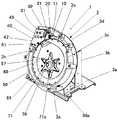
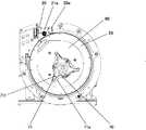
図1は、本発明の第1実施例であるコインホッパー全体を示す斜視図である。
図1に示すように、本発明に係る第1実施例のコインホッパー1は、ばら積み状態に複数のコインを保留するホッパーボウル2と、そのホッパーボウル2を上向きに傾斜して支持し固定するホッパー本体3を有している。
また、ホッパーボウル2は、ホッパー本体3より前方に突き出し、攪拌器70に向かうに従って深さが増し傾斜した形状であるホッパーヘッド部2aと、上部にコインが投入されるためのコイン投入口2bと、ホッパー本体3に取付け固定する取付け脚部2cと、ホッパー本体3に嵌合する嵌合胴部2dを有している。DESCRIPTION OF EMBODIMENTS Hereinafter, embodiments of a coin hopper according to the present invention will be described in detail with reference to the drawings based on examples.
FIG. 1 is a perspective view showing the entire coin hopper according to the first embodiment of the present invention.
As shown in FIG. 1, a
Further, the
更に、ホッパー本体3は、水平な載置台部3aと、載置台部3aに対して略直角に立設された支持側壁部3bと、嵌合胴部2dを受け入れる環状嵌合部3cと、環状嵌合部3cに一体的に形成された台座部3dと、環状嵌合部3cに一体的に形成されたホッパーボウル取付け部3eとを有し、台座部3dを介して支持側壁部3bにホッパー本体3が上向きに傾斜して固設されている。Further, the
ホッパー本体3には、図面視左上に位置して弾きローラ取付部10と、許容外コイン回避駒取付部20と、コインセンサ取付部30と、シュート40と、コインカバー45とが配設され、図面視中央に位置してホッパーボウル2の底部から前方にかけて、回転ディスク50と、固定ガイド60と、そして撹拌器70とがそれぞれ装着されている。The
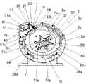
図2から図10を用いて、コインホッパー1について詳述すると、ホッパー本体3には、
図面視中央付近において、環状嵌合部3cを形成する内周側壁3fの下部に環状鍔部3gが一体形成されている。The
In the vicinity of the center in the drawing, an
この環状鍔部3gは、台座部3dとの間に介装された図7に図示する回転体51の上面外周縁を支持するためのものである。The
また、図7に示すように環状鍔部3gの表面には、ホッパー越えコイン防止駒3hが配設されている。このホッパー越えコイン防止駒3hは、回転ディスク50の回転中心Pのわずかに上方に位置している。駒3hの上面は載置台部3aに対してほぼ垂直をなしている。シュート40に向かって環状鍔部3g表面から上方に仰ぐような角度で延びている。コインを回転ディスク50から浮かして下方のホッパーボウル2内に落下させるようにしているが、内周側壁3fに沿ってシュート側へ移動した場合、この上面によってコインを起立させて、ボウル2内に落下させてシュート40とコイン係止ピン57との間にコインが挟まれないようにするためである。
なお、コイン係止ピン57は、ピンのみでなく板状等の係止材を使用しても差し支えない。よって、コイン係止ピン57は、係止体57と表現しても差し支えない。Further, as shown in FIG. 7, a hopper crossing
The
さらに、回転ディスク50からシュート40へのコイン通路には、ディスク50側から弾きローラ取付部10、許容外コイン回避駒取付部20、コインセンサ取付部30が順に配置されている。弾きローラ取付部10に弾きローラ11が装着され、許容外コイン回避駒取付部20に許容外コイン回避駒21が装着され、コインセンサ取付部30にコインセンサ31が移動可能に装着されており、中でも許容外コイン回避駒21とコインセンサ31とは互いに連動して移動可能なように装着されている。Further, in the coin path from the
同様に図面視左上のシュート40は断面チャンネル形に形成され、シュート40の内面41とホッパー本体3の台座部3d上面とで断面矩形であり、図3に示すように下方に傾斜するコイン払出し通路Pbを形成している。Similarly, the
許容外コイン回避駒21は、回転ディスク50の上面からシュート40側斜め上方に向かって仰ぐような角度で突出するような斜面が形成されている。換言すれば、駒21はほぼ直角三角形であり、その斜面は台座部3dの上面からシュート40に向かって上向きを呈している。駒21は、許容コインの通路のわずかに外側に固定される。上流のコイン移送通路Pmから移送される、シュート40に進入できないような外径を有する許容外のコインを、回転ディスク50から浮かしてホッパーボウル2内に落下させるようにしている。The non-permissible
図中、シュート40に、許容外コイン回避駒21と一体的に連結されたコインセンサ31が配置されている。シュート内面41と台座部3d上面とによってコイン払出し通路Pbを形成する。シュート40は、板金加工などで折曲された鋼板などからなる金属製の蓋体形状をなすとともに、コインセンサ31と許容外コイン回避駒21とが移動する部位にかけて切欠部43を有している。通路Pbの左端が払出し口42である。In the figure, a
コインセンサ31は、コインセンサ31がコイン払出し通路Pb内に突出しないように、シュート内面41及び台座部3d上面より後退した位置に設けられ、弾きローラ11に対して適宜間隔を有するように配設されている。
また、コインセンサ31は、弾きローラ11とシュート40との間にあって、許容外コイン回避駒21とともに、コイン移送通路Pmに対して直交方向に移動可能に設けられている。The
The
図3及び図7を用いて、上述した許容外コイン回避駒21は、許容外コイン回避駒取付部20に許容外コイン回避駒21が装着されているが、他の許容外コイン回避駒として、図15及び図16に示すように、コイン通路には、ディスク50側から許容外コイン回避駒取付部20a、弾きローラ取付部10、許容外コイン回避駒取付部20を有し、弾きローラ取付部10を挟んで、許容外コイン回避駒取付部20と許容外コイン回避駒取付部20aの2箇所の許容外コイン回避駒取付部を有しており、両許容外コイン回避駒取付部20、20a上に許容外コイン回避駒21aが設けられている。3 and 7, the non-permissible
許容外コイン回避駒21aは、長方形の細長い板状であり、ディスク50側の先端部を斜面状に形成している。また、弾きローラ11に駒21aが当たらないようにブリッジ状をなし、駒21aの両側に一体成形された図示せぬ支柱でコイン通路より上側に突出させている。The non-permissible
許容外コイン回避駒20では、弾きローラ11でコインをはじき出した後に勢いのついた許容外コインをホッパヘッド部2aに戻していたが、許容外コイン回避駒21aでは、弾きローラ11でコインをはじき出す前にディスク50から来た許容外コインは、許容外コイン回避駒21aの斜面状先端部により許容外コインをホッパヘッド部2aに戻すように構成されている。図3、図7の例では、コインの勢いによりコインがシュート40と回避駒21との間に挟まってしまう恐れがあったが、図15、図16の例においては許容外コインに勢いがついていないので、コインボウル2内へ確実に落下される。
よって、許容外コイン回避駒20に変わり許容外コイン回避駒21aを用いてもかまわない。In the non-permissible
Therefore, instead of the non-permissible
前述のコインセンサ31は、例えばU字形電磁センサが使用され、被検出体であるコインの検知部31aが埋め込まれたそのU字形部を通路Pbの両サイドに位置するよう配置してある。また、コインセンサ31は、コイン払出し通路Pbと直交する方向に切欠部43を移動するとともに、シュート40の幅方向をその内面41とホッパー本体3上面とに沿ってコイン払出し通路Pbを跨ぐようにシュート40に備えられている。For example, a U-shaped electromagnetic sensor is used as the
すなわち、コインセンサ31の検知部31aは、シュート内面41及び台座部3d上面からコイン払い出し通路Pb内に突出しないように、シュート40に位置付けられている。換言すれば、コインが検知部31aに衝突しないのである。That is, the
なお、コインセンサ31は、倒立U字形電磁センサに限らず倒立U字形の光学セン
サも使用可能であり、非U字形の電磁センサなども使用可能である。また、非U字形電磁センサの場合は、検知部が、シュート内面41側か或いは台座部3d側の何れかの面から後退してシュート40に位置付けられる。換言すれば、コイルが検知部に衝突しないためである。The
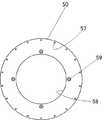
図3において、固定ガイド60はそのほぼ4分の3の外周が、回転ディスク50と同心円状かつ小径であり、4分の1が接線方向に延び、全体としてティアドロップ形状である。所要のコインの厚みの、少なくとも2/3の板厚の板状体たとえばステンレス板材など比較的硬く剛性のある金属で形成され、回転ディスク50の上面に対してその板厚分突出して台座部3dに固定されている。
固定ガイド60の厚みは、多くともコインの厚みと同一である。なぜなら、送給ガイド63a、63bにおいて、コインが2枚重なって案内されないためである。In FIG. 3, the outer periphery of the fixed
The thickness of the fixed
また、固定ガイド60は、回転ディスク50上にあって、その外周側面と回転ディスク50の表面とでコイン移動経路Pmを形成している。
すなわち、固定ガイド60は、外周側面をなすその板厚面が回転ディスク50表面に対して直角な面を有し、その直角な面と回転ディスク50の表面とでコインをコイン払出し方向にガイドしながら移動させるコイン移送通路Pmを形成している。The fixed
That is, the fixed
この固定ガイド60には、円形なコイン送給ガイド63aと円形なコイン送給ガイド63aの上部外周に、接線方向に延びる水平なコイン送給ガイド63bが形成されている。The fixed
また、水平なコイン送給ガイド63bは、厚みの異なるコインに対応するべく他の円形なコイン送給ガイド63aより肉厚形状にするため、その水平なコイン送給ガイド63bの先端部側面に別ピース61を取り外し可能に固定している。この別ピースを取り付けることにより、ガイド63bの厚みは、コイン厚さを超える。また、別ピース61のガイド面は回転ディスク上面と鋭角をなすよう傾斜している。この傾斜により弾きローラ11によりコインが別ピース61のガイド面に押された場合、コイン分力作用のため回転ディスク上面に押し付けられ、コインがガイド63bから落下することなく押し出される。
なお、この別ピース61、送給ガイド部自体を肉厚に一体形成してもよい。Further, the horizontal
In addition, you may integrally form this another
また、別ピース61は、平面視台形状をなして、固定ガイド60に取着固定するねじ用穴61cと、固定ガイド60に位置決めする図示しない位置決めピンが裏面に植設されている。
なお、別ピース61は、回転ディスク50と同様に鋼材からなり、特に金属製のコインの接触による経年磨耗に耐え得るように焼入れされた鋼鉄が好ましい。Further, the
The
さらに、固定ガイド60は、図7、8及び図10に示すように第2伝動ギヤ83bの凸面83cが位置可能な円形孔62と、別ピース61を、取着固定するための取着孔61bと位置決めピンが挿入される位置決め孔61aとが穿設され、スペーサ65を介して台座部3dに取着固定する取着孔64とが穿設されているものである。Further, as shown in FIGS. 7, 8 and 10, the fixing
固定ガイド60の円孔58は、第2伝動ギヤ83bの凸面83cに嵌合されることから、その中心が、回転ディスク50と同軸をなす図7に示す中心位置Pに対して下方向に僅かに偏倚するとともに、回転ディスク50の反時計回り寄りに僅かに偏倚して位置付けられて形成されている。
なお、この固定ガイド60は、回転ディスク50に対しては、スペーサ65によって接触しないように僅かな間隙を有してホッパー本体3に取着固定されている。Since the
The fixed
回転ディスク50のコイン係止ピン57の間に位置したコインに中心Pよりも上方に位置する場合、送給ガイド63a及び回転ディスク50の上面によって支えられ、かつ、係止ピン57によって押されて円形な送給ガイド63aを転動しながら、コイン移送通路Pmを下流方向に送給される。When the coin positioned between the coin locking pins 57 of the
さらに、コインは、固定ガイド60の接線方向にほぼ水平に延びる送給ガイド63bと、コイン係止ピン57によって押されながら、1枚ごとのコインが整列された状態で、弾きローラ11と相対する別ピース61を取着した水平な送給ガイド63bに移動する。Further, the coin is opposed to the
この時、コインは弾きローラ11によって、送給ガイド63b側に押される。しかし、別ピース61によってガイド63bの厚みが厚いため弾きローラ11によって押し付けられた場合であってもコインとガイドとの間の摩擦力が増加し落下することがない。異なる厚みのものであっても、或いはその厚み方向の両隅角がだれた形状であっても、別ピース61によって水平な送給ガイド63b上に保持される。At this time, the coin is pushed to the
さらに、コインは、コイン係止ピン57の押出力によって、弾きローラ11の付勢力に抗して突き進む。弾きローラ11の接触位置がコインの直径部を過ぎた直後、コインは、弾きローラ11の復帰力によって通路Pb内に向かって弾き出される。Further, the coin advances against the urging force of the
この時、シュート40のコイン払出し通路Pbを通過できない外径をもったコインは、弾きローラ11とシュート40との間に設けられた許容外コイン回避駒21の斜面に衝突し、その上端部が上方に跳ね上げるため通路Pbから外され、よって排斥されホッパーボウル2内に落下する。
もしくは、弾きローラ11でコインを叩く前にディスク50から来た許容外コインは、許容外コイン回避駒21aの斜面状先端部により許容外コインをホッパーボウル2内に戻すように落下させる。At this time, the coin having an outer diameter that cannot pass through the coin payout passage Pb of the
Alternatively, the non-permissible coin that has come from the
また、この許容外コイン回避駒21もしくは21aは、コイン払出し通路Pbに対してコインセンサ31を連動して上下移動できるので、コインの外径に応じて予め上下調整ができる。Further, since the
弾きローラ11によって弾き出され、許容外コイン回避駒21もしくは21aの下方を通過したコインは、シュート40内に進入する。Coins that have been ejected by the repelling
シュート40内に進行したコインは、弾きローラ11と適宜間隔を有してシュート40のコイン払出し通路Pbに直交方向に跨って設けられたコインセンサ31によって検知される。計数され、この検知信号を図示しない計数器によってカウントし、コインの払い出し数とする。そしてシュート40のコイン払出口42を経て払い出される。Coins that have advanced into the
このシュート40内に弾き出されたコインは、弾きローラ11とシュート40内のコインセンサ31とが適宜間隔を有して離れているので、弾きローラ11によって弾き切ってからコインセンサ31によって検知されることになる。The coin flipped into the
また、コインセンサ31は、許容外コイン回避駒21もしくは21aの上下移動に伴って、その検知部31aが、コイン払出し通路Pbを直交するように切欠部43を上下移動するとともに、シュート内面41と台座部3d上面とからコイン払出し通路Pb内に突出しないように、許容外コイン回避駒取付部20もしくは20と20aに備え付けたので、仮に、シュート40内に弾き出されたコインが、重なり合ってシュート40のコイン払出し通路Pb内に滞留し、コイン詰まりが発生したとしても、コイン詰まりの内圧によるコインセンサ31の破損を防止することができる。Further, the
シュート40のコイン払出し通路Pb内に滞留したコイン詰まりによる内圧は、シュート内面41とホッパー本体3上面とに加わり、シュート40とホッパー本体3がコインセンサ31を保護する。The internal pressure due to the coin clogging staying in the coin payout passage Pb of the
コインセンサ31の検出信号をカウントした払い出し数が所定数に達した場合、コイン払出し終了信号が出力されてギヤードモータ80は停止し、コインホッパー1は停止する。When the number of payouts counted by the detection signal of the
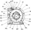
図4及び図4の一部拡大図である図5に示すように、台座部3dの背面には、モータ例えばギヤードモータ80と、弾きローラ取付部10と、許容外コイン回避駒取付部20と、コインセンサ取付部30とが配設されている。As shown in FIG. 5 which is a partially enlarged view of FIG. 4 and FIG. 4, a motor, for example, a geared
弾きローラ取付部10は、弾きローラ11と、弾きローラ11を回転自在に軸着した回動アーム12と、回動アーム12に、常時、図示しないばね手段などによって下向きの弾性力を印加するばね軸13と、弾きローラ11が移動する弾きローラ用長孔14とから構成され、弾きローラ11は、ホッパー本体3に形成された弾きローラ用長孔14からコイン移送通路Pm側に露出するようになっている。The repelling
図5、図6及び図15に示すように、許容外コイン回避駒取付部20は、許容外コイン回避駒21を、もしくは許容外コイン回避駒取付部20と20aに設けられた許容外コイン回避駒21aを上下移動するスライダー23と、そのスライダー23の下部にあって回動することによってスライダー23を上下移動するカム22と、そのカム22を回動可能に取着し、支持側壁部3bに穿設された複数のノッチ孔25を選択して回動することで、カム22の回動位置を調整するためのカム22に回動自在に固定されたハンドル26とから構成されている。As shown in FIGS. 5, 6, and 15, the non-permissible coin avoidance
支持側壁部3bには、カム22の回転中心からの半径に沿ってノッチ孔25が複数個形成されている。 A plurality of notch holes 25 are formed in the
なお、カム22は、カムの円板中心より変心させてカム軸27を設けている。これにより、カム軸27に固定されているハンドル26を回転することにより、カムは、変心して回転するのでカムに接触しているスライダー23の最下位部でアングル状に曲がり、カム22方向へ延びたスライダー下板29を上下動させることができる。よって、スライダー下板29と一体であるスライダー23が上下移動することとなる。スライダー下板29がカム22と接触し、ハンドル26の突起部24がノッチ孔25に挿入されカム22が固定される。すなわち、スライダー23が位置決めされ固定される。カムの外周部分において、カム22が固定されるノッチ孔25に相対した複数個の個所は、円形状のカム22の外周部を平面状に加工したカム平面部28を有し、スライダー下板29がカム22に密着するようになされている。 The
許容外コイン回避駒21もしくは許容外コイン回避駒21aを上下調整するには、スライダー23を上下移動するべくハンドル26を回して適宜ノッチ孔25を選んでハンドル26先端の突起部24をノッチ孔25に挿入して調整位置を決める。これにより、カム22が所定角度で停止するため、その位相におけるカムの半径に応じた位置にスライダー23が位置する。換言すれば、駒21もしくは駒21a及びコインセンサ31が選択ノッチ孔25に対した位置に保持される。In order to vertically adjust the non-permissible
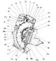
図7に示すように、コインホッパー1の中央縦断面斜視図において、図面視中央より右上に位置してギヤードモータ80の出力軸81と、回転ディスク50を回転させる回転体51と、その回転体51の中央に一体に形成された伝動内歯ギヤ52とが示されている。As shown in FIG. 7, in the central longitudinal sectional perspective view of the
上述したコインホッパー1によれば、所要枚数のコイン払い出し信号を受けて始動するギヤードモータ80は、回転ディスク50と撹拌器70を回転する。According to the above-described
攪拌器70の動力伝達等は、ホッパー本体3に配設された出力軸81に軸着された駆動ギヤ82と、駆動ギヤ82に噛合する第1伝動ギヤ83aとともに一体形成された第2伝動ギヤ83bを有する伝動ギヤ83と、伝動ギヤ83を回転可能に支持し回転ディスク50の回転中心Pよりも下方にあって、かつ、回転方向の下流側に駆動ギヤ82を配置して枢軸84、伝動ギヤ83とを含む、攪拌器70は第2伝動ギヤに形成されている。第2伝動ギヤ83bは伝動内歯ギヤ52に噛み合っており、回転体51に固定された回転ディスク50を回転するように構成されている。The power transmission and the like of the
すなわち、出力軸81は、ギヤードモータ80によって時計回りに回転し、第1伝動ギヤ83aは反時計回りに回転し、反時計回りに回転する第2伝動ギヤ83bは伝動内歯ギヤ52に噛合して回転体51を反時計回りに回転し、回転体51に取着固定された回転ディスク50を反時計回りに回転するようにしている。
また、第1伝動ギヤ83aによって反時計回りに回転する第2伝動ギヤ83bは枢軸84を中心に撹拌器70を反時計回りに回転するようにしている。That is, the
The
このように、撹拌器70は、第1、第2伝動ギヤ83a、83bを介して回転され、さらに回転ディスク50は伝動内歯ギヤ52を介在して回転するので、互いに反時計回りに回転する。In this way, the
したがって、回転ディスク50は伝動ギヤ52を介してギヤ83から動力伝達を受けて回転するので、攪拌器とは回転数が異なる。回転ディスク50と攪拌器70との回転比は5:6の範囲が好ましい。Therefore, the
したがって、回転ディスク50と撹拌器70とが互いに同一の反時計回りに回転しても、コインに与える撹拌能力が異なってくる。Therefore, even if the
したがって、撹拌器70は、その回転軸をなす枢軸84を、回転ディスク50と固定ディスク60との同軸中心Pに対して下方向に偏倚するとともに、回転ディスク50の反時計回り寄りに偏倚した位置をなす。Therefore, the
この撹拌器70の偏倚位置は、コインが、撹拌器70によって撹拌される中で回転ディスク50の回転方向側に移動するにしたがって、そのコインの移動が緩慢になる個所、すなわち時計の文字盤で例えると、ホッパー本体3の正面視6時から5時、4時方向の個所と略一致する。The biased position of the
比較的多くのコインが密集する個所ではこのコイン移動が緩慢になるので、なぜなら、回転ディスク50の回転によってコインも同方向に送られる。しかし、係止体によって1つずつコインが送り出されるので送り出されないコインが滞留するのである。この個所に、撹拌器70を位置付けて撹拌することによって、多くのコインを撹拌することができる。Since the coin movement is slow at a place where a relatively large number of coins are concentrated, the coins are also sent in the same direction by the rotation of the
しかも、回転ディスク50は、撹拌器70とは回転数が異なり、撹拌器70に比べて回転数が少ないと同時に回転速度が遅いので、この回転ディスク50に、回転数が多く、回転速度が速い撹拌器70を同一方向に回転することによって、撹拌器70は、コインを攪拌しコインの姿勢を積極的に変える。そのためコインは、係止体によってフックされ易くなり歯抜けすることなく係止体に係止される。In addition, the
撹拌器70は、半径方向に放射状に形成された6本の腕71を有し星形をしているので、コインの撹拌、移動及び解しに相乗効果をもたらして撹拌効率を向上しており、さらに腕71は、先端に向かって鋭角をなす尖形部71aと、回転方向側面を俯角に形成してなるコイン逃がし面71bとによってコインとの衝接摩擦を緩和して撹拌器70にかかる負荷を軽減している。The
撹拌器70は、固定ガイド60の上面にあって、耐磨耗性の優れた合成ゴム、たとえばウレタンゴムよりなる適宜厚みを有する。The
また、撹拌器70の中心部は、上面側がホッパーボウル2側に突出するようにコーン状に膨出した形状を有するとともに、下面側が枢軸84の頭部に遊嵌する嵌合孔72を形成している。Further, the central portion of the
この撹拌器70は、腕71の基部周辺に撹拌器70を第2伝動ギヤ83bをネジにより固定するべく取着孔83fが穿設されている。The
上述の半径方向に放射状に形成された6本の腕71を有し星形をした撹拌器70は、図15及び図16に示すように、撹拌器70の腕71を3本にすることができる。先端に向かって鋭角をなす尖形部71fと、回転方向側面を俯角に形成してなるコイン逃がし面71eは、6本の腕71を有した撹拌器70の尖形部71aより尖形部71fは滑らかな湾曲状に傾斜した形状となっている。また、コイン逃がし面71eもコイン逃がし面71bよりも逃がし角を多少大きくしてある。換言すれば、コイン逃がしのための傾斜角を多少大きくしてある。As shown in FIGS. 15 and 16, the
6本の腕71の撹拌器70の場合、攪拌性がよい反面、コインが腕71の逃がし面71bへ食い込むことがある。しかし、尖形部71fを滑らかな湾曲状にし、コイン逃がし面71eも逃がし角を多少大きくしたことによって、コインが攪拌器70の上面側へスムーズに案内され腕71の逃がし面71eへ食い込むことが起こらなくなった。In the case of the
なお、撹拌器70の形状を星形やほぼ三角形の形状としたが、これに限らず、枢軸84を中心に半径方向に延びる単一の腕によっても実施できることは勿論である。また、攪拌器70は、回転ディスク50と逆方向に回転させることができる。The shape of the
さらに、図中、回転体51は、その上面に、回転ディスク50を面一致に嵌合するように同心円状に突出した突状内周縁51aを形成するとともに、その突状内周縁51aに伝動内歯ギヤ52が形成された円形の中空部58を有する。回転体51は、たとえばポリアセタール、アセタール樹脂などからなるドーナツ状の薄い円板形状をなしている。
また、回転体51は、その下面に、図示しない環状のスラスト軸受けが嵌装される環状溝54が形成され、図3に示したホッパー本体3の環状鍔部3gと台座部3dとの間にあって回転可能に支持されている。スラスト軸受は、例えばリング状の支持帯に適宜間隔をおいて複数の円錐台状コロが嵌め込まれたものである。Further, in the drawing, the rotating
Further, the rotating
さらに、回転体51の上面には、回転ディスク50を一体的に取着固定する取着孔55が穿設されている。Further, an
また、図8に示すように、回転体51には、その中心軸より下位置で回転体51の外周側面に接し、回転体51の中心を通る垂線に対し線対象に2個の外周面の縁で回転する外側ガイドローラ56a,56aが設けられている。更に、伝動内歯ギヤ52の下部に有する内周側面には、中心軸より上方向位置に回転体51の内周側面に接し、回転体51の中心を通る垂線に対し線対象に2個及び図7に示すように回転体51の中心を通る垂線上で、かつ、伝動内歯ギヤ52の真下部の位置に1個、合わせて3個が内周面の縁で回転する内側ガイドローラ56b、56b、56bが設けられている。In addition, as shown in FIG. 8, the rotating
回転ディスク50は、ホッパー本体3の環状鍔部3gの内径に遊嵌する外径を有するとともに、回転体51の突状内周縁51aに嵌合する内径の円孔58を有する、たとえば鋼材からなるドーナツ状の薄い円板形状をなしている。The
また、この回転ディスク50は、その上面に、所定間隔で配置された複数のコイン係止ピン57が植設され、さらに回転体51に一体的に固定するための取着孔59が穿設されているIn addition, a plurality of coin locking pins 57 arranged at predetermined intervals are planted on the upper surface of the
この伝動ギヤ83の第2伝動ギヤ83bは、その上面部に、固定ガイド60を嵌合する凸面部83cが形成されるとともに、枢軸84に嵌入する貫通孔83dと、撹拌器位置決め兼回り止め用孔83eとが穿設され、さらに撹拌器取着孔83fが螺設されている。
なお、伝動ギヤ83の第1伝動ギヤ83aは、その下面が直接ホッパー本体3の表面に接触しないように、ホッパー本体3上面との間に図示しないスラストワッシャーが介装され、枢軸84を中心にホッパー本体3上で円滑に回転するようになっている。The
The
このスラストワッシャーは、例えば合成高分子化合物よりなる繊維と黒鉛粒子とからなるもので、面圧による塑性変形がなく、摩擦係数の小さいものである。This thrust washer is made of, for example, a fiber made of a synthetic polymer compound and graphite particles, has no plastic deformation due to surface pressure, and has a small friction coefficient.
ここで、本発明のコインホッパーにおけるコインの適応範囲について記載すると、前述したように各種コイン径に対応するようにコインセンサ31を取り付け一体化したスライダー23を上下可動してコインセンサ31の位置をコイン径に合わせるように適宜コインセンサ31の位置調整を行なうことで、広範囲にコイン径に対応させることができる。Here, the applicable range of coins in the coin hopper of the present invention will be described. As described above, the
例えばユーロコインを例に説明する。10セントユーロの直径は、19.7φであり2ユーロの直径は、25.7φである。本発明のコインホッパー1においては、コインセンサ31のコイン径に対応した位置調整のみで他に部品の交換をせずとも10セントユーロの直径から2ユーロの直径まではコインの払い出しが行なえる。For example, a euro coin will be described as an example. The diameter of 10 cents euro is 19.7φ and the diameter of 2 euros is 25.7φ. In the
更に、25.7φ以上のコインに適応させるには、図9および図10に示した回転ディスク50および固定ガイド60を大径のコイン径に対応するように交換することで、26φから38φまでの大径のコインに対応することが可能となる。具体的には、63aを更に小径な固定ディスクに変更し、係止体57の間隔がより大きい回転ディスク50に交換する。Furthermore, in order to adapt to coins of 25.7φ or more, the
さらに、これら交換用回転ディスクと交換用固定ガイドをコインサイズに対応して複
数組み合わせることによって、一台のコインホッパーで多種のコインの払い出しに対応処理できる。Further, by combining a plurality of these replacement rotating disks and replacement fixed guides corresponding to the coin size, it is possible to handle various coins with a single coin hopper.
このように、コインサイズに対応した交換用回転ディスクと交換用固定ガイドとに交換しても、回転ディスクのコイン係止ピン57と、固定ガイドの送給ガイドとによって転動支持しながら安定した姿勢でコインを送給し、計数し、払い出すことができ、従来装置のように、棚ホイールとピンホイールの組み合わせを替えるたびにコインとピン同士との位置関係のずれを起因とするコインの不安定送給による送給むらなどが生じる、というようなことはなく、効率的且つ安定したコイン送給ができる。As described above, even when the replacement rotating disk corresponding to the coin size is replaced with the replacement fixing guide, the rotating disk is stably supported by rolling by the
また、図10に示すように、固定ガイド60には、別ピース61を取着した水平なコイン送給ガイド63bの下方を鉤状に切欠したコイン逃げガイド66が形成されており、撹拌器70と回転ディスク50とに対して逆行移動するコインの逃げ場を形成することが好ましい。As shown in FIG. 10, the fixed
次に本発明の第2実施例を図11〜図14を用いて説明する。第1実施例と同一の構成は、同一符号で示す。尚、本実施例の基本的構成は第1実施例の図1〜図10を用いて説明した構成と同一である。よって第1実施例で詳細に説明した基本構成については説明が重複するので第2実施例においては基本構成についての説明は省略する。Next, a second embodiment of the present invention will be described with reference to FIGS. The same components as those in the first embodiment are denoted by the same reference numerals. The basic configuration of this embodiment is the same as that described with reference to FIGS. 1 to 10 of the first embodiment. Accordingly, since the description of the basic configuration described in detail in the first embodiment is duplicated, the description of the basic configuration in the second embodiment is omitted.
図11にコインホッパ1における第2実施例の伝達機構図を示す。
図11に示す第2実施例は、所定間隔に配置された複数のコイン係止ピン57によりコインを1枚ずつ送り出す回転ディスク50と、伝動内歯ギヤ52と、駆動ギヤ82と、伝動ギヤ83と、枢軸84と伝導ギヤの逆転防止の機能を有するワンウェイクラッチ100を具備する構成となっている。FIG. 11 shows a transmission mechanism diagram of the second embodiment of the
In the second embodiment shown in FIG. 11, a
図12は、伝動ギヤ83の軸孔に伝動ギヤ83の逆転防止の機能を有するワンウェイクラッチを伝動ギヤ83に圧入し固定する前のワンウェイクラッチ100を伝動ギヤ83から取外した分解図である。
また、図13は、伝動ギヤ83の軸孔に伝動ギヤ83の逆転防止の機能を有するワンウェイクラッチ100を圧入した伝動ギヤ83の正面図である。FIG. 12 is an exploded view in which the one-
FIG. 13 is a front view of the
伝動ギヤ83の中心軸にワンウェイクラッチ100を圧入し固定して用いることにより、回転ディスクのバックラッシュを軽減することができる。従って、伝動ギヤ83がワンウェイクラッチ100を有しない構成の場合においては、駆動ギヤのバックラッシュ及び伝導ギヤ83のバックラッシュが伝動内歯ギヤ52に伝達されるために伝動内歯ギヤ52でのバックラッシュが増大化される。When the one-
すなわち、ギヤードモータ80によって駆動ギヤ82は、時計回りに回転し、第1伝動ギヤ83aと第2伝動ギヤ83bとが一体構成された伝動ギヤ83は、反時計回りに回転する。そこで、伝動ギヤ83と共にワンウェイクラッチ100も反時計回りに回転する。
ワンウェイクラッチ100を伝動ギヤ83と枢軸84との間に介在させた伝動ギヤ83は、逆回転が抑制され伝動ギヤ83は反時計方向へのみ回転可能となる。駆動ギヤ82及び伝動ギヤ83が停止状態の時には、駆動ギヤ82のギヤ歯と伝動ギヤ83を構成する第2伝動ギヤ83bとのギヤ歯の噛み合いにおいて、各ギヤの歯は、反時計回転方向のみの歯側方向が接触する。よって、ギヤ全体のバックラッシュが無くなり、それぞれのギヤへの負荷及びギヤの摩耗を軽減することができる。That is, the
In the
次に図14において、回転体51の温度及び又は湿度における微少寸法変化への対応のための構成について説明する。
回転体51は、熱可塑性樹脂(ポリアセタール)によって成形されている。特にポリアセタール樹脂は、温度及び又は湿度の環境変化を受けやすく、水分の吸収性が高いことや温度の影響を受けやすい樹脂である。Next, referring to FIG. 14, a configuration for dealing with a minute dimension change in the temperature and / or humidity of the
The rotating
回転体51は、上記したポリアセタール樹脂を材質として製作されているため温度及び又は湿度の変化の影響を受け微妙に膨張・収縮する。数値で示すと100μ〜200μ程度であるが、回転体51及び回転ディスク50のスムースな回転に影響を与える。Since the rotating
よって、回転体51が温度及び又は湿度の変化を大きく受けても、回転体51の膨張・収縮に対し、回転体51への回転駆動に影響を受けないような許容できる位置に図14に示すように、回転体51には、その中心線Xより下位置で回転体51の外周側面に接し、回転体51の中心線Yに対し線対象に2個の外周面の縁で回転する外側ガイドローラ56a,56aが設けられており、回転体51の中心点C1からの角度b1で示すと片側37.5°が好ましい。また、回転体51の内周側面には、その中心線Xより下方向位置で回転体51の内周側面に接し、回転体51の中心線Yに対し線対象に2個の内周面の縁で回転する内側ガイドローラ56b、56bが設けられており、回転体51の中心点C1からの角度a1で示すと片側62°が好ましい。
ここでは、外側ガイドローラ56a,56aを回転体51の中心点C1からの角度b1で片側37.5°、内側ガイドローラ56b、56bを回転体51の中心点C1からの角度a1で片側62°として示したが、適宜よい角度に調整することでよく、上記設定角度に拘ったものではない。Accordingly, even if the
Here, the
従って、外側ガイドローラ56a,56aと内側ガイドローラ56b、56bを回転体51に設け、上記したポリアセタール樹脂の特性の影響を軽減している。
つまり、温度もしくは湿度が高いときは、回転体51が僅かに膨張するので、各2個の外側ガイドローラ56a,56aと内側ガイドローラ56b、56bよって、回転体51が膨張して高さや内径の変化分の影響を最小限にするために各2個の外側ガイドローラ56a,56aと内側ガイドローラ56b、56bを位置決めし取り付けてある。換言すれば、回転体51の外周側面に接した外側ガイドローラ56a,56aの位置から回転体51の高さが膨張のため微妙に高くなり持ち上がる、また、内径も微妙に大きくなるが、外側ガイドローラ56a,56aの最適な取付位置において、回転体51の高さの変化分が最小限になる。同時に、回転体51の内周側面に接した内側ガイドローラ56b,56bの影響も最小限になる。
また、温度や湿度が低いときは、回転体51が僅かに収縮するので、各2個の内側ガイドローラ56b、56bと外側ガイドローラ56a,56aによって、回転体51が収縮したときの高さや内径の変化分の影響を最小限にするように各2個の内側ガイドローラ56b、56bと外側ガイドローラ56a,56aを位置決めし取り付けてある。換言すれば、回転体51の内周側面に接した内側ガイドローラ56b,56bの位置から回転体51の内径が収縮のため微妙に小さくなり、また、高さも微妙に小さくなるため回転体51が全体的に下がるが、内側ガイドローラ56b,56bの最適な取付位置において、回転体51の内径の変化分が最小限になる。同時に、回転体51の外周側面に接した外側ガイドローラ56a,56aの影響も最小限になる。Therefore, the
That is, when the temperature or humidity is high, the rotating
Further, when the temperature and humidity are low, the rotating
よって、温度及び又は湿度の変化における回転体51の膨張・収縮に対する回転駆動への悪影響が軽減され、温度及び又は湿度の変化に対しても回転体51はその影響を受けることなくスムースな回転駆動が可能である。Therefore, the adverse effect on the rotational drive due to the expansion and contraction of the
なお、上述の実施例では本発明のコインホッパーの第1実施例及び第2実施例について説明したが、本発明は上記実施例に限定されるものではなく、その要旨を逸脱しない範囲で種々変更、改良が可能である。In the above-described embodiment, the first and second embodiments of the coin hopper of the present invention have been described. However, the present invention is not limited to the above-described embodiment, and various modifications can be made without departing from the scope of the present invention. Improvements are possible.
ホッパー本体に回転可能且つ着脱可能に設けてなるディスク上にコイン係止ピンを複数設けた回転ディスクと、回転ディスクを介在してホッパー本体に取着固定した固定ガイドと、固定ガイドを介在して回転ディスクと固定ガイドとの同軸中心に対してその回転中心が偏倚した撹拌器とを備えることによって、ホッパーボウル内にばら積みされたコインを効率よく撹拌して移動し、この撹拌によってコインの効率的な送給を可能にしている。 A rotating disk provided with a plurality of coin locking pins on a disk that is rotatable and detachable on the hopper body, a fixed guide that is fixedly attached to the hopper body via the rotating disk, and a fixed guide By providing a stirrer whose rotational center is deviated with respect to the coaxial center of the rotating disk and the fixed guide, the coins stacked in the hopper bowl are efficiently stirred and moved. Is possible.
1 コインホッパー
2 ホッパーボウル
3 ホッパー本体
11 弾きローラ
20 許容外コイン回避駒取付部
20a 許容外コイン回避駒取付部
21 許容外コイン回避駒
21a 許容外コイン回避駒
22 カム
23 スライダー
24 突起部
25 ノッチ孔
26 ハンドル
30 コインセンサ取付部
31 コインセンサ
40 シュート
41 シュート内面
42 コイン払出し口
50 回転ディスク
52 伝動内歯ギヤ
57 コイン係止体
60 固定ガイド
61 別ピース
63a 円形なコイン送給ガイド
63b 水平なコイン送給ガイド
70 撹拌器
71 腕
71a 尖形部
71f 尖形部
71b コイン逃がし面
71e コイン逃がし面
80 モータ
82 駆動ギヤ
83 伝動ギヤ
83a 第1伝動ギヤ
83b 第2伝動ギヤ
84 枢軸
P 同軸中心
Pb コイン払い出し通路
Pm コイン移送通路
100 ワンウェイクラッチ
DESCRIPTION OF
Claims (18)
Translated fromJapanese前記撹拌器(70)は、前記ホッパー本体(3)に配設されたモータ(80)の出力軸(81)に設けられた駆動ギヤ(82)と、該駆動ギヤ(82)に噛合する第1伝動ギヤ(83a)と一体形成された第2伝動ギヤ(83b)で構成される伝動ギヤ(83)と、前記伝動ギヤ(83)を回転可能に支持する前記枢軸(84)とによって回転するように成され、前記回転ディスク(50)は、前記第2伝動ギヤ(83b)に噛合する伝動内歯ギヤ(52)を介在して前記撹拌器(70)と同一方向に回転するように設けられてなることを特徴とする請求項1に記載のコインホッパー。
The stirrer (70) meshes with a drive gear (82) provided on an output shaft (81) of a motor (80) disposed on the hopper body (3) and the drive gear (82). A transmission gear (83) constituted by a second transmission gear (83b) integrally formed with one transmission gear (83a) and the pivot (84) rotatably supporting the transmission gear (83) The rotating disk (50) is provided to rotate in the same direction as the agitator (70) with a transmission internal gear (52) meshing with the second transmission gear (83b). The coin hopper according to claim 1, wherein the coin hopper is formed.
ホッパー本体(3)の背面部に有するスライダー(23)と、前記スライダー(23)に設けられたコインセンサ取付部(30)に装着されたコイン計数用コインセンサ(31)とを有し、前記コインセンサ(31)と一体となった前記スライダ(23)の下部位置に設けられた前記スライダ(23)を上下動するためのカム(22)と、支持側壁部(3b)を挟んで前記カム(22)に回動自在に固定されたハンドル(26)を有することを特徴とする請求項1に記載のコインホッパー。A coin sensor (31) position adjustment mechanism for different coin sizes,
A slider (23) on the back surface of the hopper body (3), and a coin counting coin sensor (31) mounted on a coin sensor mounting portion (30) provided on the slider (23), A cam (22) for vertically moving the slider (23) provided at a lower position of the slider (23) integrated with a coin sensor (31), and the cam sandwiching a support side wall (3b) The coin hopper according to claim 1, further comprising a handle (26) rotatably fixed to (22).
Since the rotating body (51) assembled with the rotating disk (50) expands and contracts depending on temperature and humidity, an inner guide roller (56b) and an outer guide roller (56a) are provided to absorb the change. A plurality of inner guide rollers (56b) are provided in close contact with the inner peripheral side surface of the rotating body (51), and a plurality of outer guide rollers (56a) are provided in close contact with the outer peripheral side surface of the rotating body (51). The coin hopper according to claim 1, wherein the coin hopper is provided.
Priority Applications (6)
| Application Number | Priority Date | Filing Date | Title |
|---|---|---|---|
| JP2004247722AJP4810691B2 (en) | 2003-12-12 | 2004-08-27 | Coin hopper |
| TW093137775ATWI263173B (en) | 2003-12-12 | 2004-12-07 | Coin hopper |
| EP04029363AEP1544805B1 (en) | 2003-12-12 | 2004-12-10 | Coin hopper |
| US11/008,866US7497769B2 (en) | 2003-12-12 | 2004-12-10 | Coin hopper |
| DE602004009520TDE602004009520T2 (en) | 2003-12-12 | 2004-12-10 | The coin hopper |
| KR1020040104237AKR100668255B1 (en) | 2003-12-12 | 2004-12-10 | Coin hopper |
Applications Claiming Priority (3)
| Application Number | Priority Date | Filing Date | Title |
|---|---|---|---|
| JP2003414354 | 2003-12-12 | ||
| JP2003414354 | 2003-12-12 | ||
| JP2004247722AJP4810691B2 (en) | 2003-12-12 | 2004-08-27 | Coin hopper |
Publications (2)
| Publication Number | Publication Date |
|---|---|
| JP2005196731Atrue JP2005196731A (en) | 2005-07-21 |
| JP4810691B2 JP4810691B2 (en) | 2011-11-09 |
Family
ID=34525511
Family Applications (1)
| Application Number | Title | Priority Date | Filing Date |
|---|---|---|---|
| JP2004247722AExpired - Fee RelatedJP4810691B2 (en) | 2003-12-12 | 2004-08-27 | Coin hopper |
Country Status (6)
| Country | Link |
|---|---|
| US (1) | US7497769B2 (en) |
| EP (1) | EP1544805B1 (en) |
| JP (1) | JP4810691B2 (en) |
| KR (1) | KR100668255B1 (en) |
| DE (1) | DE602004009520T2 (en) |
| TW (1) | TWI263173B (en) |
Cited By (3)
| Publication number | Priority date | Publication date | Assignee | Title |
|---|---|---|---|---|
| JP2008067754A (en)* | 2006-09-12 | 2008-03-27 | Samii Kk | Game medium put-out device |
| JP2010176362A (en)* | 2009-01-29 | 2010-08-12 | Kyoraku Sangyo Kk | Medal conveyance device for game machine |
| WO2011081183A1 (en)* | 2009-12-28 | 2011-07-07 | グローリー株式会社 | Coin dispenser and coin handling apparatus |
Families Citing this family (4)
| Publication number | Priority date | Publication date | Assignee | Title |
|---|---|---|---|---|
| JP4997410B2 (en)* | 2005-07-01 | 2012-08-08 | 旭精工株式会社 | Coin hopper |
| TWM329217U (en)* | 2007-09-19 | 2008-03-21 | Shang Yang Ind Co Ltd | Guided knife of a coin counting device |
| LT3235360T (en)* | 2011-03-22 | 2019-11-11 | Prec Planting Llc | SEED DOSER |
| JP6402332B2 (en)* | 2015-09-09 | 2018-10-10 | 旭精工株式会社 | Coin hopper |
Citations (12)
| Publication number | Priority date | Publication date | Assignee | Title |
|---|---|---|---|---|
| JPS5063997A (en)* | 1973-08-01 | 1975-05-30 | ||
| JPS57123572U (en)* | 1981-01-27 | 1982-08-02 | ||
| JPS5941094A (en)* | 1982-08-31 | 1984-03-07 | 角野 博光 | Hopper type coins dispensor |
| JPS6024689A (en)* | 1983-07-20 | 1985-02-07 | 旭精工株式会社 | Coin feeder |
| JPS6267690A (en)* | 1985-09-20 | 1987-03-27 | グローリー工業株式会社 | Coin feeder |
| JPH0194495A (en)* | 1987-10-06 | 1989-04-13 | Laurel Bank Mach Co Ltd | Selector for coin processing apparatus |
| JPH0447491A (en)* | 1990-06-13 | 1992-02-17 | Asahi Seiko Kk | Coin sending device |
| JPH0528340A (en)* | 1991-07-19 | 1993-02-05 | Asahi Seiko Kk | Coin sending device |
| JPH0651959U (en)* | 1992-12-18 | 1994-07-15 | 株式会社オーイズミ | One-sheet restricting device in a coin sending device |
| JPH087142A (en)* | 1994-06-17 | 1996-01-12 | Nippon Signal Co Ltd:The | Coin storage discharging mechanism |
| JP2001134800A (en)* | 1999-11-04 | 2001-05-18 | Sanyo Electric Co Ltd | Coin dispenser |
| JP2003216996A (en)* | 2002-01-18 | 2003-07-31 | Nissetsu Sangyo Kiki Co Ltd | Medal paying-out device |
Family Cites Families (18)
| Publication number | Priority date | Publication date | Assignee | Title |
|---|---|---|---|---|
| US2848158A (en)* | 1958-08-19 | Power driven fare collecting and registering apparatus | ||
| US4036242A (en) | 1973-08-01 | 1977-07-19 | Spiral Step Tool Company | Hopper payout for various coin denominations |
| US4148331A (en)* | 1977-06-10 | 1979-04-10 | Bally Manufacturing Corporation | Coin-agitating method and means for coin-counting and dispensing machines |
| US4574824A (en)* | 1984-07-10 | 1986-03-11 | Igt | Agitator for coin hopper |
| GB8625531D0 (en)* | 1986-10-24 | 1986-11-26 | Coin Controls | Coin dispensing apparatus |
| JPS63314868A (en)* | 1987-10-03 | 1988-12-22 | Nec Corp | Manufacture of mos semiconductor device |
| US4923430A (en)* | 1987-10-14 | 1990-05-08 | Kabushiki Kaisha Sigma | Coin payout apparatus in gaming device |
| JP2946468B2 (en)* | 1990-03-13 | 1999-09-06 | 旭精工株式会社 | Coin sending device |
| US5098339A (en)* | 1991-01-23 | 1992-03-24 | 7's Unlimited, Inc. | Coin feeding device |
| US5190495A (en)* | 1991-02-14 | 1993-03-02 | Bally Manufacturing Corporation | High capacity coin hopper for a gaming machine |
| US5163868A (en)* | 1991-06-12 | 1992-11-17 | Adams Thomas P | Powered rail coin sorter |
| US5295899A (en)* | 1992-03-03 | 1994-03-22 | Adams Thomas P | Two disc coin handling apparatus |
| TW382111B (en)* | 1998-05-21 | 2000-02-11 | Asahi Seiko Co Ltd | Coin accommodation funnel device |
| AU761666B2 (en)* | 1999-02-24 | 2003-06-05 | Asahi Seiko Kabushiki Kaisha | A coin dispensing apparatus |
| JP3821983B2 (en)* | 1999-04-28 | 2006-09-13 | グローリー工業株式会社 | Coin handling passage device for coin handling machine |
| JP4235743B2 (en)* | 1999-06-25 | 2009-03-11 | 旭精工株式会社 | High speed coin payout device |
| US6350193B1 (en)* | 2000-07-17 | 2002-02-26 | International Game Technology | Coin hopper coin feeder mechanism |
| NL1019509C2 (en)* | 2001-12-06 | 2003-06-10 | Suzo Internat Nl B V | Device for dispensing disc-shaped objects such as coins. |
- 2004
- 2004-08-27JPJP2004247722Apatent/JP4810691B2/ennot_activeExpired - Fee Related
- 2004-12-07TWTW093137775Apatent/TWI263173B/ennot_activeIP Right Cessation
- 2004-12-10KRKR1020040104237Apatent/KR100668255B1/ennot_activeExpired - Fee Related
- 2004-12-10EPEP04029363Apatent/EP1544805B1/ennot_activeExpired - Lifetime
- 2004-12-10DEDE602004009520Tpatent/DE602004009520T2/ennot_activeExpired - Lifetime
- 2004-12-10USUS11/008,866patent/US7497769B2/enactiveActive
Patent Citations (12)
| Publication number | Priority date | Publication date | Assignee | Title |
|---|---|---|---|---|
| JPS5063997A (en)* | 1973-08-01 | 1975-05-30 | ||
| JPS57123572U (en)* | 1981-01-27 | 1982-08-02 | ||
| JPS5941094A (en)* | 1982-08-31 | 1984-03-07 | 角野 博光 | Hopper type coins dispensor |
| JPS6024689A (en)* | 1983-07-20 | 1985-02-07 | 旭精工株式会社 | Coin feeder |
| JPS6267690A (en)* | 1985-09-20 | 1987-03-27 | グローリー工業株式会社 | Coin feeder |
| JPH0194495A (en)* | 1987-10-06 | 1989-04-13 | Laurel Bank Mach Co Ltd | Selector for coin processing apparatus |
| JPH0447491A (en)* | 1990-06-13 | 1992-02-17 | Asahi Seiko Kk | Coin sending device |
| JPH0528340A (en)* | 1991-07-19 | 1993-02-05 | Asahi Seiko Kk | Coin sending device |
| JPH0651959U (en)* | 1992-12-18 | 1994-07-15 | 株式会社オーイズミ | One-sheet restricting device in a coin sending device |
| JPH087142A (en)* | 1994-06-17 | 1996-01-12 | Nippon Signal Co Ltd:The | Coin storage discharging mechanism |
| JP2001134800A (en)* | 1999-11-04 | 2001-05-18 | Sanyo Electric Co Ltd | Coin dispenser |
| JP2003216996A (en)* | 2002-01-18 | 2003-07-31 | Nissetsu Sangyo Kiki Co Ltd | Medal paying-out device |
Cited By (5)
| Publication number | Priority date | Publication date | Assignee | Title |
|---|---|---|---|---|
| JP2008067754A (en)* | 2006-09-12 | 2008-03-27 | Samii Kk | Game medium put-out device |
| JP2010176362A (en)* | 2009-01-29 | 2010-08-12 | Kyoraku Sangyo Kk | Medal conveyance device for game machine |
| WO2011081183A1 (en)* | 2009-12-28 | 2011-07-07 | グローリー株式会社 | Coin dispenser and coin handling apparatus |
| JP2011138259A (en)* | 2009-12-28 | 2011-07-14 | Glory Ltd | Coin dispenser and coin handling apparatus |
| US8720665B2 (en) | 2009-12-28 | 2014-05-13 | Glory Ltd. | Coin feeding machine and coin handling machine |
Also Published As
| Publication number | Publication date |
|---|---|
| KR20050058970A (en) | 2005-06-17 |
| DE602004009520D1 (en) | 2007-11-29 |
| EP1544805B1 (en) | 2007-10-17 |
| JP4810691B2 (en) | 2011-11-09 |
| US20050153646A1 (en) | 2005-07-14 |
| EP1544805A1 (en) | 2005-06-22 |
| DE602004009520T2 (en) | 2008-07-31 |
| KR100668255B1 (en) | 2007-01-12 |
| US7497769B2 (en) | 2009-03-03 |
| TWI263173B (en) | 2006-10-01 |
| TW200523821A (en) | 2005-07-16 |
Similar Documents
| Publication | Publication Date | Title |
|---|---|---|
| EP2830025B1 (en) | Coin dispensing apparatus | |
| JP2008097322A5 (en) | ||
| JP4810691B2 (en) | Coin hopper | |
| JP2014146134A (en) | Coin dispensing device | |
| JPH03158991A (en) | Hopper type medal discharging device | |
| JP2014146134A5 (en) | ||
| GB2369476A (en) | A rotary disk for a coin hopper | |
| CN101315713B (en) | coin hopper | |
| JP3139697B2 (en) | Hopper equipment | |
| EP1612744B1 (en) | Coin dispensing apparatus for large coins | |
| JP5382510B2 (en) | Coin hopper | |
| JP2010262520A5 (en) | ||
| JP3049198U (en) | Hopper equipment | |
| JP2847402B2 (en) | Hopper type medal payout device | |
| JP7752895B2 (en) | Coin hopper and coin processing device | |
| JP3026806B1 (en) | Disc rotor for transferring coins in hopper type coin dispenser | |
| JP5604705B2 (en) | Coin exit device for coin hopper | |
| JP5370737B2 (en) | Coin hopper | |
| JP2003123112A (en) | Coin paying-out device | |
| JPH10277257A (en) | Hopper equipment | |
| JP2004086528A (en) | Hopper type coin delivery device | |
| JP2001236545A (en) | Reinforced structure for disk rotor for coin conveyance in hopper type coin dispenser | |
| JPH0330931Y2 (en) | ||
| JP2006251925A (en) | Coin hopper | |
| JP4635134B2 (en) | Sphere counting device |
Legal Events
| Date | Code | Title | Description |
|---|---|---|---|
| A621 | Written request for application examination | Free format text:JAPANESE INTERMEDIATE CODE: A621 Effective date:20070820 | |
| A977 | Report on retrieval | Free format text:JAPANESE INTERMEDIATE CODE: A971007 Effective date:20100517 | |
| A131 | Notification of reasons for refusal | Free format text:JAPANESE INTERMEDIATE CODE: A131 Effective date:20100702 | |
| A521 | Request for written amendment filed | Free format text:JAPANESE INTERMEDIATE CODE: A523 Effective date:20100806 | |
| A131 | Notification of reasons for refusal | Free format text:JAPANESE INTERMEDIATE CODE: A131 Effective date:20110324 | |
| A521 | Request for written amendment filed | Free format text:JAPANESE INTERMEDIATE CODE: A523 Effective date:20110328 | |
| TRDD | Decision of grant or rejection written | ||
| A01 | Written decision to grant a patent or to grant a registration (utility model) | Free format text:JAPANESE INTERMEDIATE CODE: A01 Effective date:20110802 | |
| A01 | Written decision to grant a patent or to grant a registration (utility model) | Free format text:JAPANESE INTERMEDIATE CODE: A01 | |
| A61 | First payment of annual fees (during grant procedure) | Free format text:JAPANESE INTERMEDIATE CODE: A61 Effective date:20110802 | |
| R150 | Certificate of patent or registration of utility model | Ref document number:4810691 Country of ref document:JP Free format text:JAPANESE INTERMEDIATE CODE: R150 Free format text:JAPANESE INTERMEDIATE CODE: R150 | |
| FPAY | Renewal fee payment (event date is renewal date of database) | Free format text:PAYMENT UNTIL: 20140902 Year of fee payment:3 | |
| R250 | Receipt of annual fees | Free format text:JAPANESE INTERMEDIATE CODE: R250 | |
| R250 | Receipt of annual fees | Free format text:JAPANESE INTERMEDIATE CODE: R250 | |
| R250 | Receipt of annual fees | Free format text:JAPANESE INTERMEDIATE CODE: R250 | |
| R250 | Receipt of annual fees | Free format text:JAPANESE INTERMEDIATE CODE: R250 | |
| R250 | Receipt of annual fees | Free format text:JAPANESE INTERMEDIATE CODE: R250 | |
| R250 | Receipt of annual fees | Free format text:JAPANESE INTERMEDIATE CODE: R250 | |
| R250 | Receipt of annual fees | Free format text:JAPANESE INTERMEDIATE CODE: R250 | |
| LAPS | Cancellation because of no payment of annual fees |