JP2005193590A - Printing device - Google Patents
Printing deviceDownload PDFInfo
- Publication number
- JP2005193590A JP2005193590AJP2004004115AJP2004004115AJP2005193590AJP 2005193590 AJP2005193590 AJP 2005193590AJP 2004004115 AJP2004004115 AJP 2004004115AJP 2004004115 AJP2004004115 AJP 2004004115AJP 2005193590 AJP2005193590 AJP 2005193590A
- Authority
- JP
- Japan
- Prior art keywords
- network
- packet
- attack
- address
- printing apparatus
- Prior art date
- Legal status (The legal status is an assumption and is not a legal conclusion. Google has not performed a legal analysis and makes no representation as to the accuracy of the status listed.)
- Withdrawn
Links
Images


Landscapes
- Computer And Data Communications (AREA)
- Data Exchanges In Wide-Area Networks (AREA)
- Accessory Devices And Overall Control Thereof (AREA)
Abstract
Translated fromJapaneseDescription
Translated fromJapanese本発明はネットワークに接続した印刷装置のセキュリティ機構に関わり、特に他の端末からの攻撃を防御し、攻撃者の情報をネットワーク上に通知する印刷装置のセキュリティ機構に関する。 The present invention relates to a security mechanism of a printing apparatus connected to a network, and more particularly, to a security mechanism of a printing apparatus that prevents attacks from other terminals and notifies attacker information on the network.
現在まで、攻撃者を防ぐために用意されている手段としては、暗号またはファイアウォールが標準的かつ普通である。前者は、通信の途中でのデータの改暫や盗聴を防ぐ事ができる事に特徴がある。また、後者は、ネットワークの一定の範囲をその外部から保護する事に特徴がある。ここでは特に後者の場合について考察する。まずファイアウォールとは、保護されたネットワーク(ローカルネットワーク)と、インターネットまたは他のネットワーク群との間に設置され、その間のアクセスを制限するための、コンポーネントあるいはコンポーネント群のことである。それを設置すると、すべての内外からのデータは、ファイアウォールを通過するため、セキュリティの方針によって決められたデータのみ、通過させるという制御が可能となる(例えば、特許文献1参照)。 To date, cryptography or firewalls are standard and common as a means to prevent attackers. The former is characterized in that it is possible to prevent data alteration or wiretapping during communication. The latter is characterized by protecting a certain range of the network from the outside. Here, the latter case will be considered in particular. First, a firewall is a component or a component group that is installed between a protected network (local network) and the Internet or another network group and restricts access therebetween. When it is installed, all the data from inside and outside pass through the firewall, so that only the data determined by the security policy can be controlled (see, for example, Patent Document 1).
また、ファイアウォール内の個々の端末で、起動しているプロセスの個数、ネットワークインターフェイスのトラフィック、特定ファイルのアクセス状況等の内部状態を監視することにより、侵入検出を行い、異常と判断した場合に、自計算機のリソースアクセスの制御および、ファイアウォールを含む他計算機への侵入の通知を行うものである。
前述のファイアウォールを使用したネットワークセキュリティシステムにおいては、ネットワーク管理者はファイアウォールを使用することにより、監視する範囲を限定することができる反面、クラッカーがファイアウォールをすり抜けてローカルネットワーク内に侵入した場合に、ローカルネットワーク内の端末に攻撃を仕掛けられる可能性がある。この場合には、ローカルネットワーク内の端末には攻撃の防御機能や検知機能が入っていないために、容易に侵入される場合が存在する。 In the network security system using the firewall described above, the network administrator can limit the range to be monitored by using the firewall. There is a possibility of attacking terminals in the network. In this case, a terminal in the local network does not have an attack defense function or a detection function, and thus may be easily invaded.
また、ローカルネットワーク内に存在する各端末がネットワークアクセスを監視することにより、侵入検出を行い、異常と判断した場合に、自計算機のリソースアクセスの制御及び、ファイアウォールを含む他計算機への侵入の通知を行うシステムも提案されているが、各端末内での通知情報の管理のし易さなどに問題がある場合があった。 In addition, each terminal in the local network monitors network access to detect intrusions, and when it is determined to be abnormal, it controls resource access of its own computer and notifies intrusions to other computers including firewalls. However, there are cases where there is a problem in the ease of management of notification information in each terminal.
本発明はこのような事情を考慮してなされたものであり、その目的とするところは、ネットワーク経由での攻撃を受けた場合にその攻撃を検知し、攻撃元との通信を遮断することが可能な印刷装置を提供することにより印刷装置の管理者への負担の軽減を図る。また、印刷装置が攻撃を検知した際に、攻撃者の情報を他の印刷装置や端末に通知することにより、攻撃による事態の悪化を未然に防止して、管理者の負担の軽減を図ることにある。 The present invention has been made in consideration of such circumstances, and the purpose of the present invention is to detect an attack when an attack is made via a network and to block communication with the attack source. By providing a possible printing apparatus, the burden on the administrator of the printing apparatus is reduced. In addition, when the printing device detects an attack, the attacker's information is notified to other printing devices and terminals, so that the situation caused by the attack is prevented from worsening and the burden on the administrator is reduced. It is in.
この発明は下記の構成を備えることにより上記課題を解決できるものである。 The present invention can solve the above problems by providing the following configuration.
(1)ネットワークに接続するためのネットワークインターフェイス部(NIC部)を備え、特定の端末からのネットワーク経由での通信の許可/禁止を行うことが可能な印刷装置であって、前記印刷装置は、ネットワーク経由で取得したパケットを監視するためのパケット監視手段と、前記パケット監視手段を使用することによって受信したパケットが前記印刷装置へのネットワーク攻撃であるか否かを判断するための攻撃検知手段と、ネットワーク経由での通信の許可/禁止の対象となる特定の端末のネットワーク識別子をアドレスブックとして保持するアドレスブック管理手段とを備え、前記印刷装置は前記攻撃検知手段によって、前記印刷装置自身がネットワーク経由での攻撃を受けていると検知した場合、前記パケット監視手段は攻撃パケットの送信元端末のネットワーク識別子を認識し、前記アドレスブック管理手段は前記ネットワーク識別子を通信禁止端末として前記アドレスブックに対して書き込み、また前記攻撃パケットの送信元端末からの通信を遮断することを特徴としたネットワークセキュリティ機構を備えることを特徴とした印刷装置。 (1) A printing apparatus including a network interface unit (NIC unit) for connecting to a network and capable of permitting / prohibiting communication via a network from a specific terminal, wherein the printing apparatus includes: Packet monitoring means for monitoring packets acquired via the network, and attack detection means for determining whether or not a packet received by using the packet monitoring means is a network attack on the printing apparatus; Address book management means for holding a network identifier of a specific terminal that is permitted / prohibited for communication via a network as an address book, and the printing apparatus itself is a network by the attack detection means. If it is detected that the attack is via, the packet monitoring means Recognizing the network identifier of the sender terminal of the attack packet, the address book management means writing the network identifier to the address book as a communication-prohibited terminal, and blocking communication from the sender terminal of the attack packet A printing apparatus comprising a network security mechanism characterized by the above.
(2)前記(1)に於いて、前記端末のネットワーク識別子とはIPアドレスであることを特徴としたネットワークセキュリティ機構を備えることを特徴とした印刷装置。 (2) A printing apparatus according to (1), further comprising a network security mechanism characterized in that the network identifier of the terminal is an IP address.
(3)前記(1)に於いて、前記アドレスブック及びアドレスブック管理手段は、通信の許可及び禁止をそれぞれ複数個ずつ独立して保持することが可能であることを特徴とするネットワークセキュリティ機構を備えることを特徴とした印刷装置。 (3) The network security mechanism according to (1), wherein the address book and the address book management means can independently hold a plurality of communication permissions and prohibitions. A printing apparatus comprising:
(4)ネットワークに接続するためのネットワークインターフェイス部(NIC部)を備え、特定の端末からのネットワーク経由での通信の許可/禁止を行うことが可能な印刷装置であって、前記印刷装置は、ネットワーク経由で取得したパケットを監視するためのパケット監視手段と、前記パケット監視手段を使用することによって受信したパケットが前記印刷装置へのネットワーク攻撃であるか否かを判断するための攻撃検知手段と、前記印刷装置が接続されるネットワーク上に存在する他のデバイスのネットワーク識別子をリストとして保持する印刷装置アドレス保持手段と、前記印刷装置が接続されるネットワーク上の特定の装置に対してネットワーク経由で情報を通知する情報通知手段とを備え、前記印刷装置は前記攻撃検知手段によって、前記印刷装置自身がネットワーク経由での攻撃を受けていると検知した場合、前記パケット監視手段は攻撃パケットの送信元端末のネットワーク識別子を認識し、前記印刷装置アドレス保持手段に保持されているネットワーク識別子の宛て先に対して、前記情報通知手段は攻撃パケットの送信元端末のネットワーク識別子の情報を通知することを特徴としたネットワークセキュリティ機構を備えることを特徴とした印刷装置。 (4) A printing apparatus including a network interface unit (NIC unit) for connecting to a network and capable of permitting / prohibiting communication via a network from a specific terminal, wherein the printing apparatus includes: Packet monitoring means for monitoring packets acquired via the network, and attack detection means for determining whether or not a packet received by using the packet monitoring means is a network attack on the printing apparatus; A printing apparatus address holding means for holding a list of network identifiers of other devices existing on the network to which the printing apparatus is connected, and a specific apparatus on the network to which the printing apparatus is connected via the network Information notifying means for notifying information, and the printing apparatus has the attack detecting means Therefore, when it is detected that the printing apparatus itself has been attacked via the network, the packet monitoring unit recognizes the network identifier of the transmission source terminal of the attack packet and is held in the printing apparatus address holding unit. A printing apparatus comprising a network security mechanism characterized in that the information notification means notifies the network identifier of the attack packet transmission source terminal to the destination of the network identifier.
(5)前記(4)に於いて、前記他のデバイスのネットワーク識別子とはIPアドレスであることを特徴としたネットワークセキュリティ機構を備えることを特徴とした印刷装置。 (5) The printing apparatus according to (4), further comprising a network security mechanism in which the network identifier of the other device is an IP address.
(6)ネットワークに接続するためのネットワークインターフェイス部(NIC部)を備え、特定の端末からのネットワーク経由での通信の許可/禁止を行うことが可能な印刷装置であって、前記印刷装置は、ネットワーク経由で取得したパケットを監視するためのパケット監視手段と、ネットワーク経由で取得したパケットが、ネットワークの攻撃者(クラッカー)の通知情報であるか否かを認識し、クラッカーのネットワーク識別子を認識するための情報認識手段と、ネットワーク経由での通信の許可/禁止の対象となる特定の端末のネットワーク識別子をアドレスブックとして保持するアドレスブック管理手段とを備え、前記NIC部が受信したパケットが、他のデバイスから送られてきたクラッカーの通知情報であった場合、前記アドレスブック管理手段は前記クラッカーのネットワーク識別子を通信禁止端末として前記アドレスブックに対して書き込み、また前記クラッカーのネットワーク識別子からの通信を遮断することを特徴としたネットワークセキュリティ機構を備えることを特徴とした印刷装置。 (6) A printing apparatus including a network interface unit (NIC unit) for connecting to a network and capable of permitting / prohibiting communication via a network from a specific terminal, wherein the printing apparatus includes: Packet monitoring means for monitoring packets acquired via the network, whether the packets acquired via the network are notification information of network attackers (crackers), and recognize the network identifier of the cracker Information recognition means, and address book management means for holding a network identifier of a specific terminal that is permitted / prohibited for communication via a network as an address book, and the packet received by the NIC unit is other than If it is the notification information of the cracker sent from the device of The less book management means comprises a network security mechanism characterized in that the network identifier of the cracker is written to the address book as a communication-prohibited terminal, and communication from the network identifier of the cracker is blocked. apparatus.
(7)前記(6)に於いて、前記ネットワーク識別子とはIPアドレスであることを特徴としたネットワークセキュリティ機構を備えることを特徴とした印刷装置。 (7) The printing apparatus according to (6), further comprising a network security mechanism in which the network identifier is an IP address.
(8)前記(6)に於いて、前記アドレスブック及びアドレスブック管理手段は、通信の許可及び禁止をそれぞれ複数個ずつ独立して保持することが可能であることを特徴とするネットワークセキュリティ機構を備えることを特徴とした印刷装置。 (8) The network security mechanism according to (6), wherein the address book and the address book management means can independently hold a plurality of communication permits and prohibitions. A printing apparatus comprising:
本発明によれば印刷装置自身がネットワーク攻撃を検知することが可能であるため、攻撃を検知した場合には攻撃元から送信されるIPパケットの受信を禁止して、同時に通信禁止アドレス帳に攻撃元のIPアドレスを追記するため、印刷装置の管理者の負担を軽減させ、且つ安全な印刷装置を提供することが可能になる。また、検知した攻撃元IPアドレスを他の装置に通知する機能を備えることにより、それぞれの装置の管理者の負担を軽減させることが可能になる。また、攻撃元IPアドレス情報の通知を受信した印刷装置は、攻撃元から送信されるIPパケットの受信を禁止して、同時に通信禁止アドレス帳に攻撃元のIPアドレスを追記するため、印刷装置の管理者の負担を軽減させ、且つ安全な印刷装置を提供することが可能になる。 According to the present invention, since the printing apparatus itself can detect a network attack, when an attack is detected, reception of an IP packet transmitted from the attack source is prohibited, and at the same time, an attack is made on the communication prohibited address book. Since the original IP address is additionally written, it is possible to reduce the burden on the administrator of the printing apparatus and provide a safe printing apparatus. Also, by providing a function for notifying other devices of the detected attack source IP address, it is possible to reduce the burden on the administrator of each device. Further, the printing apparatus that has received the notification of the attack source IP address information prohibits the reception of the IP packet transmitted from the attack source and simultaneously adds the attack source IP address to the communication prohibited address book. It is possible to reduce the burden on the administrator and provide a safe printing apparatus.
このように、本発明によれば印刷装置単体としてのセキュリティ機能の確保と、ネットワーク全体としてのセキュリティの確保を両立することが可能になる。 As described above, according to the present invention, it is possible to ensure both the security function of the printing apparatus alone and the security of the entire network.
以下本発明を実施するための最良の形態を、実施例により詳しく説明する。 Hereinafter, the best mode for carrying out the present invention will be described in detail with reference to examples.
本発明の第一の実施例について説明する。 A first embodiment of the present invention will be described.
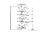
図1は本実施例のシステム構成を示すブロック図である。印刷装置101はネットワークインターフェイスを供えたMFP(Multi Function Peripheral)であり、ネットワーク経由で印刷ジョブを受信したり、使用者が端末装置上で動作するアプリケーションソフトを使用することによって印刷装置101の情報の参照や設定が可能である。また印刷装置102及び103も、ネットワーク印刷装置としての基本的な能力は印刷装置101同様であり、MFPであるものとする。印刷装置101及び102、103の構成に関しては、図2を用いて後述する。LAN104は一般的にいわれるところのLAN(Local Area Network)であり、イーサネット(R)(Ethernet(R))であるものとする。印刷装置101及び102、103や後述のファイアウォール106や端末107は全てネットワークインターフェイスカード(NIC)によってLAN104に接続される。LAN104に接続される各端末や各印刷装置はイーサネット(R)ケーブルやハブ(HUB)などを介して接続される。なお、ここでのLANの種別はイーサネット(R)であるが、これは限定されるものではなく、一般的にLANを形成するものであればよい。例えばトークンリング(Token Ring)などであってもよい。インターネット105は一般的にいわれるところのインターネット(Internet)そのものであり、TCP/IPによるパケット通信をベースとするネットワークプロトコルによって、世界中のコンピュータを相互接続したネットワークの総称。 FIG. 1 is a block diagram showing the system configuration of this embodiment. The
ローカルなLANを相互接続した形態をとっており、インターネットに参加する世界のユーザ同士が相互に通信できるようにしているため、インターネットはネットワークのネットワークと呼ばれる。ファイアウォール106は外部(インターネット105)からの不正なパケットをLAN104内に送るのを防ぐために設けられている。一般的なファイアウォールとは、組織内部のローカルなネットワークとその外部に広がるInternetとの間に、外部からの不正なアクセスを防ぐ目的で設置されるルータやホストコンピュータ、またはその機能的役割のことである。その名前の由来は火の手を防いで延焼を食い止める「防火壁(firewall)」に因んでいる。機能的には、組織内外からの通信要求を全て捕捉し、恣意的に通過させたり禁止したりすることによって、必要なサービスだけをユーザに提供しつつ、セキュリティを確保する。ただし、ファイアウォールの構築方法には特に決まった形式があるわけではなく、その組織のセキュリティに対するポリシー(方針)によって大きく異なる。一般的には、セキュリティを強化するとユーザに提供できるサービスが限定されたり制限を受けたりする。逆に、インターネットのサービスを比較的自由に使えるようにすると、その分安全性は低下する。必要なサービスだけを恣意的に通過させる方法として、アプリケーションゲートウェイ(Proxy)、サーキットレベルゲートウェイ、パケットフィルタの3種類があるが、実際のシステムではこれらを柔軟に組み合わせて安全性の高いファイアウォールシステムを構築している。本実施例でのファイアウォール106の役割は、どのような種類のIPパケットをLAN104への進入を禁止するかを規定するデータが書き込まれるファイル(フィルタ設定ファイル)を有しており、このフィルタ設定ファイルで、LAN104への進入が禁止された種類のIPパケットがインターネット105側から送信されてきたときに、そのIPパケットを廃棄してLAN104への進入を阻止する。そして、フィルタ設定ファイルで、LAN104への進入が禁止されていないIPパケットが送信されてきたときには、それをLAN104に転送する。端末装置107はパーソナルコンピュータであり、印刷装置101に印刷データを送出したり、各プロトコルを使用してLAN104に接続される各装置と通信を行うことが可能である。 The Internet is called a network of networks because it takes a form in which local LANs are interconnected and users in the world participating in the Internet can communicate with each other. The
次に、印刷装置101の構成について説明する。上述のような印刷装置101の主なる構成は、例えば図2に示すように、デバイス全体の動作制御を司るCPU201と、CPU201での動作制御のための各種プログラムやデータ等が格納されるROM202と、CPU201の主メモリや作業用エリア等を含むRAM203と、デバイス機能(プリンタ機能やコピー機能等)のエンジン204と、エンジン204の駆動を制御するエンジンコントローラ205と、ユーザから各種操作指示を受け付けたり種々の情報を表示するパネル206と、パネル206での入出力をコントロールしたりパネル206を管理するパネルコントローラ207と、各種プログラムやデータを記憶するためのハードディスクドライブ208とを備える。ハードディスクドライブ208に保持されるデータやプログラムに関しての詳細な説明は後述とする。また印刷装置104は、ハードディスクドライブ208とのアクセスを制御するディスクコントローラ209と、不揮発性RAM210と、LAN104を介して他の端末や印刷装置と双方向にデータをやりとりするためのネットワークインターフェイスカード211とを備えている。前述のハードディスクドライブ208はCPU201によって実行されるプログラムや各プログラムによって使用されるデータが格納されている。本実施例において、ハードディスクドライブ208に格納されている主なプログラムやデータには以下のものが挙げられる。パケット解析ソフトウェア212はネットワークインターフェイスカード211が受信したIPパケットを解析し、必要に応じて他のモジュールにデータを渡したり、データを廃棄するものである。受信したIPパケットの受信ポート番号やアプリケーション層プロトコルを解析し、そのパケットが渡されるべきモジュールやアプリケーションに渡す。またパケット解析ソフトウェア212は、受信IPパケットのフィルタリング機能も備えている。これは、特定の送信元IPアドレスからのパケット受信の許可や禁止を行うものである。例として、172.22.0.1というIPアドレスからのパケット受信が禁止に設定されていた場合、送信元IPアドレスが172.22.0.1であるIPパケットを受信した場合には、それがどのような種類(プロトコル)のパケットであった場合でも、パケット解析ソフトウェア212はそのパケットの破棄処理を実行し、データは他のモジュールやアプリケーションに渡されることはない。また、172.22.0.2というIPアドレスからのパケット受信が許可に設定されていた場合、送信元IPアドレスが172.22.0.2であるIPパケットを受信した場合には、その受信データは適切なモジュールやアプリケーションに渡されるが、他の送信元IPアドレスからのIPパケットは全て破棄される。ここで、通信禁止IPアドレスと通信許可IPアドレスは印刷装置101の利用者や管理者が印刷装置101の操作パネルなどを使用することによって設定することが可能であり、通信禁止IPアドレスと通信許可IPアドレスは一つではなくそれぞれに対して複数の登録が可能である。つまり、通信禁止IPアドレスを172.22.0.1, 192.168.16.1, 172.31.2.1と設定し、且つ通信禁止IPアドレスを172.22.0.2, 192.168.4.1などと設定することが可能になる。さらに、利用者や管理者が登録する通信禁止IPアドレスと通信許可IPアドレスには、IPアドレスの値に幅を持たせて設定することが可能である。例えば、通信を禁止したいIPアドレスとして172.31.0.1−172.31.0.4と設定することにより、送信元IPアドレスが172.31.0.1から172.31.0.4の間であるIPパケットは破棄される。ハードディスクドライブ208は通信許可IPアドレスのリストを格納している通信許可アドレス帳214と、通信禁止IPアドレスのリストを格納している通信禁止アドレス帳215とを持つ。印刷装置101の利用者や管理者が設定した通信許可及び禁止IPアドレスの情報はそれぞれ通信許可アドレス帳214と通信禁止アドレス帳215に保存される。通信解析ソフトウェア212は印刷装置101の電源が投入された場合などに起動されるが、起動時に通信許可アドレス帳214と通信禁止アドレス帳215にアクセスを行い、それぞれのIPアドレスをリードする。また、通信許可アドレス帳214と通信禁止アドレス帳215は他のアプリケーションによってその内容が変更される場合もあるので、通信解析ソフトウェア212は電源投入時のみならず一定の間隔でこれら2つのアドレス帳を読み出し、そのデータ内容をフィルタリングに反映する。図3は通信許可アドレス帳及び通信禁止アドレス帳215の内容のイメージである。列301はインデックスであり、本実施例に於いては最大で32個のIPアドレス(IPアドレス群)の登録が可能であることを表している。列302と列303はフィルタリングする開始IPアドレスと終了IPアドレスである。IPアドレスを単一指定したい場合には、開始IPアドレスと終了IPアドレスには同一の値が入る。図2の攻撃検知ソフトウェアとは、受信したIPパケットの内容を解析して、それがクラッカーによって送出された印刷装置101への攻撃を行うためのパケットであるか否かを判断するためのソフトウェアである。攻撃検知ソフトウェア213には、ネットワーク上で使用される代表的な攻撃パターンを元に作成された攻撃検知アルゴリズムが実装されており、攻撃を検知する。ここで、ネットワーク上で使用される代表的な攻撃について説明する。クラッカーによる攻撃と、その検知方法に関しては、特開2001−057554号公報にて説明されているので、その記載を以下に引用する。 Next, the configuration of the
まず、クラッカーによる第1の種類の攻撃として、一般にポートスキャン(Port Scan)と言われる種類の攻撃がある。この攻撃は、ネットワークに直接的な損害を及ぼすものではないが、その前段階の攻撃として用いられることが多い。この攻撃では、クラッカーは、自身の管理下にあるホストから、攻撃対象のネットワークに対して、パケット内の宛先IPアドレスや宛先ポート番号を適宜変更しながらIPパケットを繰り返し送信する。そして、それらのIPパケットに対する応答を上記ホストを介して観測することで、攻撃対象のネットワークにおいて、ファイアウォール等による制限を受けずに外部との通信に利用されているIPアドレスやポート番号を探索する。なお、ここで、前記ポート番号は、TCPあるいはUDP上で動作するアプリケーションソフトウェアのサービス種類(例えばtelnet,ftp、smtp,tftp等)を表すもので、IPパケット内のTCPヘッダあるいはUDPヘッダに付与されるデータである。この種の攻撃では、上記のようなIPパケットの送信は、通常、専用的なツールソフトウェアを用いて行われ、攻撃対象のネットワークには、宛先IPアドレスやポート番号が互いに異なり、且つ送信元IPアドレスが同一であるようなIPパケットが比較的短時間内に多数、送信される。 First, as a first type of attack by a cracker, there is a type of attack generally referred to as a port scan. Although this attack does not cause direct damage to the network, it is often used as an attack in the previous stage. In this attack, the cracker repeatedly transmits an IP packet from a host under its control to the attack target network while appropriately changing the destination IP address and the destination port number in the packet. Then, by observing the responses to those IP packets via the host, search for IP addresses and port numbers used for communication with the outside without being restricted by a firewall or the like in the attack target network. . Here, the port number represents the service type (for example, telnet, ftp, smtp, tftp, etc.) of application software that operates on TCP or UDP, and is assigned to the TCP header or UDP header in the IP packet. Data. In this type of attack, the transmission of the IP packet as described above is usually performed using dedicated tool software, and the destination IP address and the port number are different from each other in the attack target network, and the source IP Many IP packets having the same address are transmitted within a relatively short time.
そこで、本発明では、前記攻撃検知手段は、前記ネットワークにその外部から送信されてきた複数のIPパケットであって、少なくともその送信元IPアドレスが互いに同一で且つ宛先IPアドレス又は宛先ポート番号が互いに異なるものが所定時間内に所定数以上取得されたとき、第1の種類の前記攻撃がなされたことを検知する。これにより、ポートスキャンと言われる第1の種類の攻撃を確実に検知することができる。次に、クラッカーによる第2の種類の攻撃として、一般にSYN FLOODと称される種類の攻撃がある。この攻撃は、TCPの特性を利用してネットワーク内の特定のホストをダウンさせるものである。 Therefore, in the present invention, the attack detection means is a plurality of IP packets transmitted from the outside to the network, and at least the source IP address is the same and the destination IP address or the destination port number is the same. When a predetermined number of different items are acquired within a predetermined time, it is detected that the first type of attack has been made. As a result, the first type of attack called port scan can be reliably detected. Next, as a second type of attack by a cracker, there is a type of attack generally referred to as SYN FLOOD. This attack uses a characteristic of TCP to bring down a specific host in the network.
すなわち、TCPでは二つのホスト間で通信を行う場合、まず、両ホスト間で論理的なコネクションの開設処理が行われる。このコネクション開設処理では、一方のホストから他方のホストに対してSYN用IPパケットを送信する。 That is, when communication is performed between two hosts in TCP, first, a logical connection establishment process is performed between the two hosts. In this connection establishment process, a SYN IP packet is transmitted from one host to the other host.
ここで、該SYN用IPパケットは、それを詳しく言えば、上記一方のホストのIPアドレスと他方のホストのIPアドレスとをそれぞれ送信元IPアドレス、宛先IPアドレスとしたIPパケットで、そのパケット内のTCPヘッダのSYNビット及びACKビットのうちのSYNビットのみを「1」としたものである。そして、コネクション開設処理では、このSYN用IPパケットを受けた他方のホストは、前記一方のホストに対してSYN/ACK用IPパケットを送信する。ここで、該SYN/ACK用IPパケットは、詳しくは、上記他方のホストのIPアドレスと一方のホストのIPアドレスとをそれぞれ送信元IPアドレス、宛先IPアドレスとしたIPパケットで、そのパケット内のTCPヘッダのSYNビット及びACKビットを共に「1」としたものである。 More specifically, the SYN IP packet is an IP packet having the IP address of one host and the IP address of the other host as the source IP address and the destination IP address, respectively. Only the SYN bit among the SYN bit and the ACK bit of the TCP header is set to “1”. In the connection opening process, the other host that has received the SYN IP packet transmits the SYN / ACK IP packet to the one host. Here, the SYN / ACK IP packet is specifically an IP packet having the IP address of the other host and the IP address of the other host as the source IP address and the destination IP address, respectively. Both the SYN bit and the ACK bit of the TCP header are set to “1”.
さらに、コネクション開設処理では、このSYN/ACK用IPパケットを受けた前記一方のホストは、前記他方のホストに対してACK用IPパケットを送信し、このACK用IPパケットを前記他方のホストが受けることで、両ホスト間の論理的なコネクションの開設がなされる。なお、上記ACK用IPパケットは、詳しくは、前記SYN用IPパケットと同一の送信元IPアドレス及び宛先IPアドレスを有するIPパケットで、そのパケット内のTCPヘッダのSYNビット及びACKビットのうちのACKビットのみを「1」としたものである。 Further, in the connection establishment process, the one host that has received the SYN / ACK IP packet transmits an ACK IP packet to the other host, and the other host receives the ACK IP packet. Thus, a logical connection between both hosts is established. More specifically, the ACK IP packet is an IP packet having the same source IP address and destination IP address as the SYN IP packet, and the ACK of the SYN bit and ACK bit of the TCP header in the packet. Only the bit is set to “1”.
前記SYN FLOODは、このようなTCPの特性を利用する攻撃であり、この攻撃では、クラッカーは、攻撃対象のネットワークの特定のホストに対して、比較的短い時間内に多数のSYN用IPパケットを送信する。そして、それらの各SYN用IPパケットに対して上記特定ホストからSYN/ACK用IPパケットが送信されてきても、ACK用IPパケットをその特定ホストに送信しない。このような攻撃がなされたとき、上記特定ホストは、最初に送信されてきたSYN用IPパケットに対するSYN/ACK用IPパケットを送信した後、所定時間(一般に2分)は、その時間内にACK用パケットが送信されてこない限り、そのACK用パケットの受信待ち状態となる。 The SYN FLOOD is an attack that uses such characteristics of TCP. In this attack, a cracker sends a large number of IP packets for SYN to a specific host in the attack target network within a relatively short time. Send. Even if a SYN / ACK IP packet is transmitted from the specific host for each of these SYN IP packets, the ACK IP packet is not transmitted to the specific host. When such an attack is made, the specific host sends a SYN / ACK IP packet for the SYN packet that was sent first, and then ACKs within that time for a predetermined time (generally 2 minutes). Unless an ACK packet is transmitted, the ACK packet reception wait state is entered.
そして、この状態で新たなSYN用パケットが送信されてくる毎に、上記特定ホストは、新たなSYN用パケットに応じたコネクション開設処理を順番に完結すべくその新たなSYN用パケットの情報を通信処理用のバッファ領域に蓄積していく。 Each time a new SYN packet is transmitted in this state, the specific host communicates information on the new SYN packet in order to complete the connection establishment process corresponding to the new SYN packet in order. It accumulates in the buffer area for processing.
ところが、バッファ領域の大きさには限界があり、該バッファ領域が満杯になり、このようになると、前記特定ホストは、TCPの通信処理やTCP上のサービス処理を行うことができなくなり、これにより、特定ホストがダウンすることとなる。この種の攻撃(SYN FLOOD)では、前述のように、比較的短い時間内に、比較的多くのSYN用IPパケットが攻撃対象のネットワーク内の特定のホスト(特定のIPアドレスを有するホスト)に対して送信されてくる。また、これに応じて、当該特定のホストからネットワークの外部に向かって、比較的短い時間内に、多くのSYN/ACK用IPパケットが送信される。 However, the size of the buffer area is limited, and the buffer area becomes full. When this happens, the specific host cannot perform TCP communication processing or TCP service processing. The specific host will go down. In this type of attack (SYN FLOOD), as described above, a relatively large number of SYN IP packets are sent to a specific host (a host having a specific IP address) in the attack target network within a relatively short time. It is sent to. In response to this, many SYN / ACK IP packets are transmitted from the specific host to the outside of the network within a relatively short time.
さらに、それらのSYN用IPパケットあるいはSYN/ACK用IPパケットに対応して最終的に前記特定ホストに送信されてくるべきACK用パケットがその特定ホストに送信されてこない。そこで、本発明では、前記攻撃検知手段は、前記ネットワークにその外部から送信されてきたTCPに基づく複数のSYN用IPパケットであって、少なくともその宛先IPアドレスが互いに同一であるものが所定時間内に所定数以上取得され、且つ、その各SYN用IPパケットと同一の送信元IPアドレス及び宛先IPアドレスを有すると共に前記TCPに基づくACK用IPパケットが前記所定時間内に取得されなかったとき、第2の種類の前記攻撃がなされたことを検知する。 Further, the ACK packet that is to be finally transmitted to the specific host in response to the SYN IP packet or SYN / ACK IP packet is not transmitted to the specific host. Therefore, in the present invention, the attack detection means includes a plurality of SYN IP packets based on TCP transmitted from the outside to the network, and at least those whose destination IP addresses are the same within a predetermined time. And the ACK IP packet based on the TCP having the same source IP address and destination IP address as each of the SYN IP packets is not acquired within the predetermined time. Detecting that two types of attacks have been made.
あるいは、前記攻撃検知手段は、前記ネットワークからその外部に送信されたTCPに基づく複数のSYN/ACK用IPパケットであって、少なくともその送信元IPアドレスがそれぞれ互いに同一であるものが所定時間内に所定数以上取得され、且つ、前記TCPに基づくACK用IPパケットであって、前記各SYN/ACK用IPパケットの送信元IPアドレス及び宛先IPアドレスとそれぞれ同一の宛先IPアドレス及び送信元IPアドレスを有するものが前記所定時間内に取得されなかったとき、第2の種類の前記攻撃がなされたことを検知する。 Alternatively, the attack detection means may include a plurality of SYN / ACK IP packets based on TCP transmitted from the network to the outside, at least those having the same source IP address within a predetermined time. A predetermined number or more of ACK IP packets based on the TCP, and the same destination IP address and source IP address as the source IP address and destination IP address of each SYN / ACK IP packet, respectively. When what is possessed is not acquired within the predetermined time, it is detected that the second type of attack has been made.
これにより、SYN FLOODといわれる第2の種類の攻撃を確実に検知することができる。次に、クラッカーによる第3の種類の攻撃として、一般にTeardropと称される種類の攻撃がある。この攻撃は、IPパケットの分轄(所謂IPフラグメント)に係る処理の特性を利用してネットワーク内の特定のホストをダウンさせるものである。すなわち、IPパケットは、インターネット上をルータを介して転送される過程で、各ルータのデータ処理容量の関係上、分轄されることがある。 This makes it possible to reliably detect the second type of attack called SYN FLOOD. Next, as a third type of attack by a cracker, there is a type of attack generally referred to as Teadrop. This attack is to bring down a specific host in the network by using the processing characteristics relating to the division of IP packets (so-called IP fragment). In other words, IP packets may be divided due to the data processing capacity of each router in the process of being transferred over the Internet via a router.
また、各ルータにおいてIPパケットが転送される際にエラーが生じることもあり、このような場合には、ルータは、IPパケットの再送信を行う。このため、IPパケットの宛先IPアドレスのホストでは、分轄された一部の同じIPパケットが、複数受信されるということもある。 In addition, an error may occur when an IP packet is transferred in each router. In such a case, the router retransmits the IP packet. For this reason, the host having the destination IP address of the IP packet may receive a plurality of the same part of the divided IP packets.
このようなことから、IPに基づく通信では、最終的にIPパケットを受け取るホスト(宛先IPアドレスのホスト)は、受け取ったIPパケットが分轄されたものであるとき、残りの全ての分轄部分のIPパケットを受信するまで、各分割部分のIPパケットを蓄積保持し、全ての分轄部分のIPパケットを受信してから、それらを整理して元のIPパケットのデータを復元する処理を行う。 For this reason, in communication based on IP, the host that finally receives the IP packet (the host at the destination IP address), when the received IP packet is a demarcation, has the IP of all remaining demarcation parts. Until the packet is received, the IP packets of each divided part are accumulated and held, and after receiving the IP packets of all the demarcation parts, the data of the original IP packet is restored by arranging them.
前記Teardropは、このようなIPパケットの分轄に係る処理の特性を利用する攻撃であり、この攻撃では、クラッカーは、比較的短い時間内に、多数の同じ分轄部分のIPパケットを攻撃対象のネットワークの特定のホストに送信した上で、残りの分轄部分のIPパケットをその特定ホストに送信する。このような攻撃がなされたとき、上記特定ホストは、最終的に残りの分轄部分のIPパケットを受信したときに、そのIPパケットと、先に送信されてきた多量の分割部分のIPパケットとから元のIPパケットのデータを復元しようとする処理を行うため、その処理に長時間を要するものとなる。このため、該特定ホストは、事実上、ダウンしてしまうこととなる。この種の攻撃(Teardrop)では、前述の如く、比較的短い時間内に、多数の同じ分轄部分のIPパケットがネットワーク内の特定のホストに送信されてくる。 The teardrop is an attack that uses the characteristics of the processing related to the division of IP packets. In this attack, the cracker sends a large number of IP packets of the same division within a relatively short time to the attack target network. Then, the IP packet of the remaining demarcation part is transmitted to the specific host. When such an attack is made, the specific host finally receives the IP packet of the remaining demarcation part from the IP packet and a large number of divided part IP packets transmitted previously. Since a process for restoring the data of the original IP packet is performed, the process takes a long time. For this reason, the specific host will actually go down. In this type of attack (Teardrop), as described above, a large number of IP packets of the same demarcation portion are transmitted to a specific host in the network within a relatively short time.
そこで、本発明では、前記攻撃検知手段は、前記ネットワークにその外部から送信されてきた複数の分割されたIPパケットであって、同一の分割部分が所定時間内に所定数個以上取得されたとき、第3の種類の前記攻撃がなされていることを検知する。これにより、Teardropといわれる第3の種類の攻撃を確実に検知することができる。次に、クラッカーによる第4の種類の攻撃として、一般にLandと称される種類の攻撃がある。この攻撃は、送信元IPアドレス及び宛先IPアドレスが同一であるような、正規にはあり得ないIPパケットを、攻撃対象のネットワークの特定のホストに送信する攻撃である。 Therefore, in the present invention, the attack detection means is a plurality of divided IP packets transmitted from the outside to the network, and when a predetermined number or more of the same divided portions are acquired within a predetermined time. The third type of attack is detected. This makes it possible to reliably detect the third type of attack called Teadrop. Next, as a fourth type of attack by a cracker, there is a type of attack generally referred to as Land. This attack is an attack in which an IP packet that is not possible in a normal manner in which the source IP address and the destination IP address are the same is transmitted to a specific host in the attack target network.
このようなIPパケットを送信された特定ホストは、そのIPパケットの処理に手間取ることが多く、ダウンしてしまうことがしばしばある。この種の攻撃では、上記の如く、送信元IPアドレス及び宛先IPアドレスが同一であるIPパケットが、ネットワーク内の特定のホストに送信され、しかも、一般には、そのようなIPパケットが比較的短い時間内に、複数、上記特定ホストに送信される。 A specific host to which such an IP packet is transmitted often takes time to process the IP packet and often goes down. In this type of attack, as described above, an IP packet having the same source IP address and destination IP address is transmitted to a specific host in the network, and such an IP packet is generally relatively short. A plurality of messages are transmitted to the specific host within a time period.
そこで、本発明では、前記攻撃検知手段は、前記ネットワークにその外部から送信されてきた複数のIPパケットであって、その送信元IPアドレスが宛先IPアドレスと同一のアドレスとなっているものが所定時間内に所定数個以上取得されたとき、第4の種類の前記攻撃がなされていることを検知する。これにより、Landとわれる第4の種類の攻撃を確実に検知することができる。 Therefore, in the present invention, the attack detection means is a plurality of IP packets transmitted from the outside to the network, the source IP address of which is the same as the destination IP address. When a predetermined number or more are acquired within the time, it is detected that the fourth type of attack is being performed. Thereby, the 4th type attack called Land can be detected reliably.
次に、クラッカーによる第5の種類の攻撃として、ネットワーク内の特定のホストのユーザのパスワードを獲得する攻撃がある。この攻撃では、クラッカーは、攻撃対象のネットワーク内の特定のホストのユーザ名を使って、telnet等により上記特定ホストにログインし、さらに所定の辞書ファイルなどから選択した多数のパスワードを使って、その特定ホストの操作を試みる。 Next, as a fifth type of attack by the cracker, there is an attack for acquiring a password of a user of a specific host in the network. In this attack, the cracker logs in to the specific host using telnet, etc., using the user name of the specific host in the attack target network, and uses a number of passwords selected from a predetermined dictionary file, etc. Attempt to operate a specific host.
そして、このとき、その特定ホストの操作ができるか否かにより、パスワードが判明することとなる。この種の攻撃では、同一のユーザ名データを含み、しかも互いに異なるパスワードを有する多数のIPパケットが、攻撃対象のネットワークの特定ホストに送信される。 At this time, the password is determined depending on whether or not the specific host can be operated. In this type of attack, a large number of IP packets including the same user name data and having different passwords are transmitted to a specific host in the attack target network.
そこで、本発明では、前記攻撃検知手段は、前記ネットワーク内の特定のホストを操作すべく該ネットワークにその外部から送信されてきた複数のIPパケットであって、前記特定のホストに係るユーザ名データが互いに同一で、且つパスワードが互いに異なるものが所定時間内に所定数以上取得したとき、第5の種類の前記攻撃がなされていることを検知する。これにより、上記のようにパスワードを獲得する攻撃を確実に検知することができる。 Therefore, in the present invention, the attack detection means is a plurality of IP packets transmitted from the outside to the network to operate a specific host in the network, and user name data relating to the specific host When the same number and passwords different from each other are obtained within a predetermined time, it is detected that the fifth type of attack has been made. This makes it possible to reliably detect an attack for acquiring a password as described above.
次に、クラッカーによる第6の種類の攻撃として、ネットワーク内の特定のホストに、ネットワーク管理者など、ごく限られた者が、専用のパスワードを入力した状態でしか実行させることができないような処理(所謂、ルートコマンド)を行わせる攻撃がある。この攻撃は、攻撃対象のホストが搭載しているOS(Operation System)のセキュリティホールといわれるバグを利用するものである。すなわち、例えばUNIX(R)マシン(ホスト)は、バッファオーバフローといわれるセキュリティホールを有しており、このセキュリティホールは、例えばプリンタの論理名を表す「lpr」というコマンドを含む比較的大きなデータ(128文字以上のデータ)が一度に送られてきたとき、バッファがオーバフローし、そのオーバフローしたデータ内に、ルートコマンドがあると、ネットワーク管理者などのパスワードが入力されていなくても、そのルートコマンドを実行してしまうというものである。前記第6の種類の攻撃は、このようなバッファオーバフローといわれるセキュリティホールを攻撃するもので、前述の「lpr」というコマンドを含む所定サイズ以上のデータ列というような、所定のパターンのデータを含むデータ列を有するIPパケットがネットワークの特定のホストに送信される。そこで、本発明では、前記攻撃検知手段は、バッファオーバフローと言われるセキュリティホールを攻撃する所定のパターンのデータを有するデータ列を有するIPパケットを取得したとき、第6の種類の前記攻撃がなされていることを検知する。これにより、上記のような第6の種類の攻撃を検知することができる。 Next, as a sixth type of attack by a cracker, a process in which a very limited person such as a network administrator can execute a specific host in the network only with a dedicated password entered There is an attack that causes a so-called route command. This attack uses a bug called an OS (Operation System) security hole installed in the attack target host. That is, for example, a UNIX (R) machine (host) has a security hole called a buffer overflow, and this security hole includes, for example, relatively large data (128 including a command “lpr” representing a logical name of a printer). When data (more than characters) is sent at a time, the buffer overflows. If there is a route command in the overflowed data, the route command will be displayed even if a password such as a network administrator is not entered. It will be executed. The sixth type of attack attacks such a security hole called buffer overflow, and includes data of a predetermined pattern such as a data string of a predetermined size or more including the above-mentioned command “lpr”. An IP packet having a data string is transmitted to a specific host in the network. Therefore, in the present invention, when the attack detection unit obtains an IP packet having a data string having a predetermined pattern of data that attacks a security hole called buffer overflow, the attack of the sixth type is made. Detect that Thereby, the sixth type of attack as described above can be detected.
攻撃検知ソフトウェア213に実装される攻撃検知アルゴリズムも、上記のような検知アルゴリズムを有しており、攻撃を検知することが可能となっている。図2のハードディスクドライブ208には、他にSNMP通信ソフトウェアが格納されている。これは、印刷装置101上でアプリケーション層プロトコルであるSNMP(Simple Network Management Protocol)が動作するのに必要がソフトウェアであり、デバイスのデータベースであるMIB217とのアクセスや、通信パケット解析ソフトウェア212からデータを受け取ったり、またデータを送ったりといった処理を行う。MIB217とは、SNMPで使用される機器情報データベースであるMIB(Machine Information Base)である。ハードディスクドライブ208には他には、印刷の制御を行うための印刷制御ソフトウェア218や印刷装置101のオペレーティングシステムであるOS部219などが存在する。また、ネットワークインターフェイスカード211が取得した全てのパケットの内容を一時的に保管しておくためのパケットデータファイル220も備わる。本実施例で使用されるOSとは、一般的なMFPやコントローラが使用すると予想されるVxWorksやLinuxを想定している。また本実施例に於いては説明は省略するが、印刷装置が動作するための他のソフトウェアもついても、ハードディスクドライブ208に保持されているものとする。例えば、各印刷サービスの制御モジュールやデータ伸張を司るソフトウェアなどである。 The attack detection algorithm implemented in the
次に図4に示されるフローチャートを用いて、本発明の第一の実施例の全体の流れについて説明する。 Next, the overall flow of the first embodiment of the present invention will be described with reference to the flowchart shown in FIG.
まずStep401において、印刷装置101の利用者や管理者が印刷装置101の電源の投入を行う。次にStep402において、印刷装置101のシステムが起動する。これは、CPU201がハードディスクドライブ208内に保持されているOS部219及び印刷装置101がMFPとしての動作を実行できるための各種ソフトウェアなどをハードディクスドライブ208から読み出し、実行することで利用者や管理者が印刷装置101をMFPとして使用できる状態になるための処理である。 First, in step 401, the user or administrator of the
次にStep403において、受信IPパケットのフィルタリング処理を行う。ここでのフィルタリングとは、特定のIPパケットを破棄するということであり、その理由は信頼できる送信元からのIPパケットのみを受信/解析することによってネットワーク経由での攻撃から防御することが可能になるからである。受信可能なIPパケットの判断は、IPパケットの送信元IPアドレスから識別する。CPU201は通信パケット解析ソフトウェア212を読み出し、実行する。前述の通り、通信パケット解析ソフトウェア212は受信IPパケットのフィルタリング機能を備えている。通信パケット解析ソフトウェア212は、通信許可アドレス帳214及び通信禁止アドレス帳215を読み込み、それらのアドレス帳に記載されているIPアドレス情報に従って、送信元IPアドレスのフィルタリング処理を実行する。ここで、通信許可アドレス帳214や通信禁止アドレス帳215のフォーマットは図3で示されるものとする。仮に、通信禁止アドレス帳215の内容が図3で示される情報であった場合、まず通信パケット解析ソフトウェア212は、図3に示されるIndex.1のIPアドレス172.22.0.1から172.22.0.4までに含まれるIPアドレスの受信及び解析を禁止する。このIPアドレスが送信元となるIPパケットは、その内容がいかなるものであった場合でも、印刷装置101内でIPパケットの要求が実行されることはない。 Next, in Step 403, the received IP packet is filtered. The filtering here means that a specific IP packet is discarded, and the reason is that it is possible to protect against attacks via the network by receiving / analyzing only IP packets from a reliable source. Because it becomes. The determination of the receivable IP packet is made from the IP packet source IP address. The
また、図3の残りのIndex.2から32に関しても同様に、受信及び解析は禁止される。次にStep404にて、攻撃検知ソフトウェア213が起動される。攻撃検知ソフトウェア213はネットワークインターフェイスカード211が受信した全てのIPパケットを取得可能になっており、ネットワーク経由での攻撃を検知する機能が備わっている。攻撃の検知は以下のような手法で行われる。まず、攻撃検知ソフトウェア213は、単位時間あたりにネットワークインターフェイスカード211が取得した全てのIPパケットを読み出し、送信元IPアドレス及び送信先IPアドレス別に振り分けて、ハードディスクドライブ208の空き領域に格納される。つまり、攻撃検知ソフトウェア213は、送信元IPアドレスと送信先IPアドレス別にグループ化し、それぞれのグループ単位で検知処理を行う。攻撃の検知処理は、攻撃検知ソフトウェア213が前述のグループ化されたIPパケットグループをメモリ(RAM203)に読み出し、前述の攻撃検知アルゴリズムによって攻撃パケットであるか否かを識別する。 Further, the remaining Index. Similarly for 2 to 32, reception and analysis are prohibited. Next, at Step 404, the
ここで、あるIPパケット群が攻撃パケットであると検知された場合には、攻撃元IPアドレスを認識する処理であるStep407に移行する。また逆に、その単位時間あたりに取得したIPパケット全てが攻撃パケットではないと判定された場合には、メモリ(RAM203)及びハードディスクドライブ208上から、今回検知したIPパケットグループのデータを破棄して、ハードディスクドライブ208に格納されている次のIPパケットグループを攻撃識別するためにメモリ(RAM203)に読み出す(Step405)。攻撃検知のシーケンスについて、図5を用いて詳細な説明を行う。前述のように、攻撃検知アルゴリズムとして攻撃検知ソフトウェア213が有しているものは、
1)ポートスキャン検知
2)SYN FLOOD検知
3)Teardrop検知
4)LAND検知
5)パスワード不正入手検知
6)セキュリティホール攻撃検知
これらが挙げられている。本実施例では、攻撃検知ソフトウェア213は単位時間に取得されたIPパケットグループに対して、これらの攻撃検知を行うので、任意のIPパケットグループに対する検知は、6回行われることになる。Here, when it is detected that a certain IP packet group is an attack packet, the process proceeds to Step 407 which is a process of recognizing the attack source IP address. Conversely, if it is determined that all IP packets acquired per unit time are not attack packets, the IP packet group data detected this time is discarded from the memory (RAM 203) and the
1) Port scan detection 2) SYN FLOOD detection 3) Teadrop detection 4) LAND detection 5) Incorrect password detection 6) Security hole attack detection These are listed. In this embodiment, the
つまり、第一の攻撃検知を行い(Step501)、攻撃と判定されなければ第2の攻撃検知を行う(Step502)。そのように第6の攻撃検知までを行い(Step506)、全ての攻撃を検知できなかった場合には、メモリ(RAM203)及びハードディスクドライブ208に保持されているIPパケットグループを破棄する(Step406)。 That is, the first attack detection is performed (Step 501), and if the attack is not determined, the second attack detection is performed (Step 502). As such, the sixth attack detection is performed (Step 506), and when all attacks are not detected, the IP packet group held in the memory (RAM 203) and the
ここで、第1から第6の攻撃検知処理(Step501からStep506)において、攻撃パケットであると識別された場合には、攻撃元IPアドレスを認識する処理であるStep407に移行する。Step407では、攻撃パケットと判断されたIPパケットの送信元IPアドレスを認識し、メモリ内に格納する処理である。攻撃検知ソフトウェア213はIPパケットを解読し、所定の位置から送信元IPアドレスを認識して、メモリ(RAM203)にデータとして格納する。 Here, in the first to sixth attack detection processes (Step 501 to Step 506), when the packet is identified as an attack packet, the process proceeds to Step 407, which is a process for recognizing the attack source IP address. Step 407 is processing for recognizing the transmission source IP address of the IP packet determined to be the attack packet and storing it in the memory. The
次に、攻撃検知ソフトウェア213は、攻撃者からのIPパケットの受信を遮断するために、攻撃元IPアドレスを通信禁止アドレス帳215に追加する。例えば、追加以前の通信禁止アドレス帳215の内容が図3に示される内容であったと仮定する。 Next, the
図3では、Indexが1から4までの範囲でデータが記載されている。これは通信を禁止するIPアドレス個数またはIPアドレスの範囲の個数が4つ登録されていることを示す。この状態に於いて、攻撃検知ソフトウェアが攻撃元IPアドレス172.31.0.20を通信禁止アドレス帳215に書き加えた場合、その内容は図6で示されるものになる。 In FIG. 3, data is described in the range of Index from 1 to 4. This indicates that four IP addresses or IP address ranges that are prohibited from communication are registered. In this state, when the attack detection software adds the attack source IP address 172.31.0.20 to the communication prohibited
図6では、Index.1から4までは図3と同内容である。これはすでに有効になっている通信禁止IPアドレス(IPアドレス範囲)はそのまま有効であり続けることを意味する。攻撃検知ソフトウェア213は通信禁止アドレス帳215に対して、Index.5として新規に攻撃元IPアドレスを追加する(Step408)。攻撃検知ソフトウェア213が攻撃を検知した際に行う処理は以上である。 In FIG. The contents from 1 to 4 are the same as those in FIG. This means that a communication prohibited IP address (IP address range) that is already valid continues to be valid as it is. The
次にStep409において、通信パケット解析ソフトウェア212が通信禁止アドレス帳215をリロードすることによって、クラッカーが送信元となるIPパケットのフィルタリング処理を行う。前述の通り、通信パケット解析ソフトウェア212はIPパケットのフィルタリングを行う部分であるが、通信の許可/禁止が定義されているアドレス帳を定期的にリロードする機能が備わっている。リロードを行い、前回ロードしたデータと比較して差異があった場合、フィルタリングの設定を変更する。今回、攻撃検知ソフトウェア213によって通信禁止アドレス帳215は変更されているため、通信パケット解析ソフトウェア212は変更箇所である攻撃元IPアドレス172.31.0.20との通信を遮断する。つまり、今後クラッカーが送信元となるIPパケットを印刷装置101が受信した場合には、そのIPパケットはアプリケーションによって解釈されることなく破棄される。印刷装置101内での攻撃IPパケットのフィルタリング処理が終了したら、クラッカーの情報を他の印刷装置に通知する処理に移行する(Step410)。 Next, in Step 409, the communication
本実施例に於いては、クラッカーの情報はSNMPで使用されるTRAPメッセージを用いて行われる。TRAPメッセージとは、SNMPで規定されるメッセージであり、デバイスの状態が変わったときに、SNMPのエージェント側からマネージャ側に対して、管理情報の変更ということで自発的に送られるものである。本実施例では、通知するクラッカーの情報とは攻撃IPパケットの送信元IPアドレスである。Step410においてSNMP通信ソフトウェア216は、LAN104内に存在する他の印刷装置102及び103と、端末107に対してTRAPを発行する。ここで、TRAPの送信先となる印刷装置102、103及び端末107のIPアドレスは、印刷装置101の管理者によって事前に登録されており、その情報はMIB217として保持されているものとする。SNMP通信ソフトウェア216はIPパケットの送信先を上記の印刷装置または端末として、SNMPのTRAPパケットを送信する。トランスポート層のプロトコルはUDPであり、SNMPのgeneric−TRAPフィールドに入る値は、ベンダが独自に定義した事象が発生したことを示すenterpriseSpecific(6)である。またspecific−TRAPフィールドには、攻撃元IPアドレスであることを示す特定のコードと、攻撃元IPアドレスが記載される。印刷装置101が攻撃の検知と他のデバイスへの通知を行う手順は以上である。 In this embodiment, the cracker information is performed using a TRAP message used in SNMP. The TRAP message is a message defined by SNMP, and is sent spontaneously by the management information change from the SNMP agent side to the manager side when the state of the device changes. In this embodiment, the notified cracker information is the source IP address of the attack IP packet. In Step 410, the
次に、Step410において印刷装置101が送信したTRAP情報を送信先のデバイスが受信してフィルタリングを行う処理について図7のフローチャートを用いて説明する。 Next, a process in which the destination device receives the TRAP information transmitted by the
まず、図4のStep410に於いて、印刷装置101よりTRAPパケットが送信される。TRAPパケットの送信先は、印刷装置102、同103、端末107である。一例としてここでは印刷装置102内の動作について説明するが、基本的な動作は印刷装置103も端末107も同様であるものとする。印刷装置102の基本構成は印刷装置101と同様であり、MFPであるものとする。その構成は図2として説明されたものと同様である。まずStep701において、印刷装置102のネットワークインターフェイスカード211がTRAPパケットを受信した場合、受信TRAPは通信パケット解析ソフトウェア212に送られる。通信パケット解析ソフトウェア212は受信TRAPパケットの送信元IPアドレスを認識して、通信が許可されたIPアドレスであるか否かを判別する。本実施例では、印刷装置101と同102は同一のLAN上で動作する印刷装置であり、その管理者も同一であることから互いの通信は許可されているものとする。印刷装置101が送信元となるIPパケットの受信が許可されているので、TRAPパケットのアプリケーションデータはSNMP通信ソフトウェア216に渡される。次にStep702において、受信したTRAPメッセージの内容の解析(デコード)を行う。SNMP通信ソフトウェア216は、受信したSNMPパケットのPDU−Typeフィールド(Protocol Data Units−Type フィールド)の値が4であることから、それがTRAPであることを認識する。 First, at Step 410 in FIG. 4, a TRAP packet is transmitted from the
またTRAP−PDUのEnterpriseフィールドとGeneric Trapフィールド、そしてSpecific Trapフィールドの値を参照することによって、受信したTRAPがどのようなTRAPであるかを認識することが可能になる。これはSNMPのTRAP−PDUの定義として規定されているものであり、まずGeneric Trapフィールドに通知されるイベントの詳細な種別が記載される。ここでは、クラッカー情報の通知という独自の通知内容であるため、その値はenterpriseSpecific(6)である。そしてそのTRAPの内容は、Specific TrapフィールドとEnterpriseフィールドに記載される。このような手順によって、SNMP通信ソフトウェア216はクラッカーのIPアドレスを認識することが可能になる。次に印刷装置102は通知されたIPアドレスを自身の通信禁止アドレス帳215に書き込む処理を行う。SNMP通信ソフトウェア216は通信禁止アドレス帳215にアクセスして、まず通知されたクラッカーのIPアドレスが通信禁止アドレス帳215にすでに登録されているか否かを調査する(Step703)。この処理において、クラッカーのIPアドレスが通信禁止アドレス帳215に登録済みであることが認識された場合、クラッカーから受信されるIPパケットのフィルタリングはすでに実行されているということであるため、SNMP通信ソフトウェア216はその処理を中止する。Step703の処理において、クラッカーのIPアドレスは自己の通信禁止アドレス帳215に記載されていないと認識された場合、SNMP通信ソフトウェア216は通信禁止アドレス帳215にクラッカーのIPアドレスを追記する(Step704)。 Further, by referring to the values of the enterprise field, the generic trap field, and the specific trap field of the TRAP-PDU, it is possible to recognize what kind of TRAP the received TRAP is. This is defined as the definition of SNMP TRAP-PDU. First, the detailed type of the event to be notified is described in the Generic Trap field. Here, since the notification content is unique notification of cracker information, the value is enterpriseSpecific (6). Then, the contents of the TRAP are described in the Specific Trap field and the Enterprise field. By such a procedure, the
次にStep705において、通信パケット解析ソフトウェア212が通信禁止アドレス帳215をリロードすることによって、クラッカーが送信元となるIPパケットのフィルタリング処理を行う。前述の通り、通信パケット解析ソフトウェア212はIPパケットのフィルタリングを行う部分であるが、通信の許可/禁止が定義されているアドレス帳を定期的にリロードする機能が備わっている。リロードを行い、前回ロードしたデータと比較して差異があった場合、フィルタリングの設定を変更する。今回、SNMP通信ソフトウェア216によって通信禁止アドレス帳215は変更されているため、通信パケット解析ソフトウェア212は変更箇所であるクラッカーのIPアドレスとの通信を遮断する。つまり、今後クラッカーが送信元となるIPパケットを印刷装置102が受信した場合には、そのIPパケットはアプリケーションによって解釈されることなく破棄される。 Next, in
TRAPを受信した装置は以上の処理を行うが、印刷装置101から送信されたTRAPを受信した他のデバイス、即ち印刷装置103及び端末107に関しても、図7に示されるStep701からStep705の処理が行われるものとする。 The apparatus that has received TRAP performs the above processing, but the processes from Step 701 to Step 705 shown in FIG. 7 are also performed for other devices that have received TRAP transmitted from the
以上、本発明の実施例について説明したが、本発明は上記実施例に限定されるものではない。たとえば、本発明では印刷装置101から他の装置へ、クラッカーの情報を通知する際にSNMPのTRAPを使用したが、これは他のプロトコルを使用することも可能である。また、本発明においては、IPアドレスをSNMPパケットのデータとして送信したが、これはFTP(File Transfer Protocol)などを使用して、通信禁止アドレス帳そのものを他の印刷装置などに対して送付してもよい。 As mentioned above, although the Example of this invention was described, this invention is not limited to the said Example. For example, in the present invention, SNMP TRAP is used when notifying cracker information from the
このほか、本発明の要旨を逸脱しない範囲で種々の変形実施が可能である。 In addition, various modifications can be made without departing from the scope of the present invention.
101〜103 印刷装置
104 LAN
105 インターネット
106 ファイアウォール
107 端末
201 CPU
202 ROM
203 RAM
204 エンジン
205 エンジンコントローラ
206 パネル
207 パネルコントローラ
208 ハードディスクドライブ
209 ディスクコントローラ
210 NVRAM
211 ネットワークインターフェイスカード
212 通信パケット解析ソフトウェア
213 攻撃検知ソフトウェア
214 通信許可アドレス帳
215 通信禁止アドレス帳
216 SNMP通信ソフトウェア
217 MIB
218 印刷制御ソフトウェア
219 OS部
220 パケットデータファイル
301 通信禁止アドレス帳のIndex
302 通信禁止アドレス帳の開始IPアドレス
303 通信禁止アドレス帳の終了IPアドレス
401 電源投入処理
402 システムソフト起動処理
403 フィルタリング処理
404 攻撃検知ソフトウェア起動処理
405 攻撃検知処理
406 IPパケットデータ廃棄処理
407 攻撃元IPアドレス検知処理
408 通信禁止アドレス帳追記処理
409 フィルタリング処理
410 TRAP送信処理
501 第一の攻撃の検知処理
502 第二の攻撃の検知処理
503 第三の攻撃の検知処理
504 第四の攻撃の検知処理
505 第五の攻撃の検知処理
506 第六の攻撃の検知処理
701 TRAP受信処理
702 解析処理
703 通信禁止アドレス帳確認処理
704 通信禁止アドレス帳追記処理
705 フィルタリング処理101-103
105
202 ROM
203 RAM
211
218
302 Start IP address of communication prohibited
Claims (8)
Translated fromJapaneseネットワーク経由で取得したパケットを監視するためのパケット監視手段と、
前記パケット監視手段を使用することによって受信したパケットが前記印刷装置へのネットワーク攻撃であるか否かを判断するための攻撃検知手段と、
ネットワーク経由での通信の許可/禁止の対象となる特定の端末のネットワーク識別子をアドレスブックとして保持するアドレスブック管理手段とを備え、
前記印刷装置は前記攻撃検知手段によって、前記印刷装置自身がネットワーク経由での攻撃を受けていると検知した場合、前記パケット監視手段は攻撃パケットの送信元端末のネットワーク識別子を認識し、前記アドレスブック管理手段は前記ネットワーク識別子を通信禁止端末として前記アドレスブックに対して書き込み、また前記攻撃パケットの送信元端末からの通信を遮断することを特徴としたネットワークセキュリティ機構を備えることを特徴とした印刷装置。A printing apparatus including a network interface unit (NIC unit) for connecting to a network and capable of permitting / prohibiting communication via a network from a specific terminal, wherein the printing apparatus includes:
A packet monitoring means for monitoring packets acquired via the network;
Attack detection means for determining whether a packet received by using the packet monitoring means is a network attack on the printing apparatus;
An address book management means for holding a network identifier of a specific terminal to be permitted / prohibited for communication via a network as an address book;
When the printing device detects that the printing device itself is attacked via a network by the attack detection unit, the packet monitoring unit recognizes a network identifier of a transmission source terminal of the attack packet, and the address book A printing apparatus comprising a network security mechanism characterized in that the management means writes the network identifier as a communication-prohibited terminal to the address book and blocks communication from the transmission source terminal of the attack packet .
ネットワーク経由で取得したパケットを監視するためのパケット監視手段と、
前記パケット監視手段を使用することによって受信したパケットが前記印刷装置へのネットワーク攻撃であるか否かを判断するための攻撃検知手段と、
前記印刷装置が接続されるネットワーク上に存在する他のデバイスのネットワーク識別子をリストとして保持する印刷装置アドレス保持手段と、
前記印刷装置が接続されるネットワーク上の特定の装置に対してネットワーク経由で情報を通知する情報通知手段とを備え、
前記印刷装置は前記攻撃検知手段によって、前記印刷装置自身がネットワーク経由での攻撃を受けていると検知した場合、前記パケット監視手段は攻撃パケットの送信元端末のネットワーク識別子を認識し、前記印刷装置アドレス保持手段に保持されているネットワーク識別子の宛て先に対して、前記情報通知手段は攻撃パケットの送信元端末のネットワーク識別子の情報を通知することを特徴としたネットワークセキュリティ機構を備えることを特徴とした印刷装置。A printing apparatus including a network interface unit (NIC unit) for connecting to a network and capable of permitting / prohibiting communication via a network from a specific terminal, wherein the printing apparatus includes:
A packet monitoring means for monitoring packets acquired via the network;
Attack detection means for determining whether a packet received by using the packet monitoring means is a network attack on the printing apparatus;
Printing device address holding means for holding network identifiers of other devices on the network to which the printing device is connected as a list;
Information notification means for notifying information via a network to a specific device on the network to which the printing apparatus is connected,
When the printing device detects that the printing device itself is attacked via a network by the attack detection unit, the packet monitoring unit recognizes a network identifier of a transmission source terminal of the attack packet, and the printing device The information notification means includes a network security mechanism characterized in that the information notification means notifies the network identifier information of the transmission source terminal of the attack packet to the destination of the network identifier held in the address holding means. Printer.
ネットワーク経由で取得したパケットを監視するためのパケット監視手段と、
ネットワーク経由で取得したパケットが、ネットワークの攻撃者(クラッカー)の通知情報であるか否かを認識し、クラッカーのネットワーク識別子を認識するための情報認識手段と、
ネットワーク経由での通信の許可/禁止の対象となる特定の端末のネットワーク識別子をアドレスブックとして保持するアドレスブック管理手段とを備え、
前記NIC部が受信したパケットが、他のデバイスから送られてきたクラッカーの通知情報であった場合、前記アドレスブック管理手段は前記クラッカーのネットワーク識別子を通信禁止端末として前記アドレスブックに対して書き込み、また前記クラッカーのネットワーク識別子からの通信を遮断することを特徴としたネットワークセキュリティ機構を備えることを特徴とした印刷装置。A printing apparatus including a network interface unit (NIC unit) for connecting to a network and capable of permitting / prohibiting communication via a network from a specific terminal, wherein the printing apparatus includes:
A packet monitoring means for monitoring packets acquired via the network;
An information recognition means for recognizing whether a packet acquired via the network is notification information of a network attacker (cracker), and recognizing the network identifier of the cracker;
An address book management means for holding a network identifier of a specific terminal to be permitted / prohibited for communication via a network as an address book;
When the packet received by the NIC unit is the notification information of the cracker sent from another device, the address book management means writes the network identifier of the cracker to the address book as a communication prohibited terminal, A printing apparatus comprising a network security mechanism that blocks communication from the network identifier of the cracker.
Priority Applications (1)
| Application Number | Priority Date | Filing Date | Title |
|---|---|---|---|
| JP2004004115AJP2005193590A (en) | 2004-01-09 | 2004-01-09 | Printing device |
Applications Claiming Priority (1)
| Application Number | Priority Date | Filing Date | Title |
|---|---|---|---|
| JP2004004115AJP2005193590A (en) | 2004-01-09 | 2004-01-09 | Printing device |
Publications (1)
| Publication Number | Publication Date |
|---|---|
| JP2005193590Atrue JP2005193590A (en) | 2005-07-21 |
Family
ID=34818823
Family Applications (1)
| Application Number | Title | Priority Date | Filing Date |
|---|---|---|---|
| JP2004004115AWithdrawnJP2005193590A (en) | 2004-01-09 | 2004-01-09 | Printing device |
Country Status (1)
| Country | Link |
|---|---|
| JP (1) | JP2005193590A (en) |
Cited By (13)
| Publication number | Priority date | Publication date | Assignee | Title |
|---|---|---|---|---|
| JP2007251866A (en)* | 2006-03-20 | 2007-09-27 | Kyocera Mita Corp | Electronic equipment device |
| JP2008181436A (en)* | 2007-01-26 | 2008-08-07 | Fuji Xerox Co Ltd | Information processor |
| JP2010004552A (en)* | 2004-02-02 | 2010-01-07 | Cyber Solutions Inc | Unauthorized information detecting system and unauthorized attack node search system |
| JP2010167740A (en)* | 2009-01-26 | 2010-08-05 | Seiko Epson Corp | Information processing device, control method thereof, and computer program |
| JP2010218462A (en)* | 2009-03-18 | 2010-09-30 | Ricoh Co Ltd | Information processor, information processing method, and program |
| WO2016080446A1 (en)* | 2014-11-19 | 2016-05-26 | 日本電信電話株式会社 | Control device, border router, control method and control program |
| JP2016177451A (en)* | 2015-03-19 | 2016-10-06 | 日本電気株式会社 | Communication terminal, communication method and program |
| JP2017156993A (en)* | 2016-03-02 | 2017-09-07 | ソフトバンク株式会社 | Authentication server and authentication server program |
| JP6272575B1 (en)* | 2017-01-11 | 2018-01-31 | 甲賀電子株式会社 | Data communication method |
| WO2018131176A1 (en)* | 2017-01-11 | 2018-07-19 | 甲賀電子株式会社 | Data communication method |
| JP2020154832A (en)* | 2019-03-20 | 2020-09-24 | キヤノン株式会社 | Information processing equipment, its control method, and programs |
| US11146550B2 (en) | 2018-01-23 | 2021-10-12 | Koga Electronics Co., Ltd. | Communication line mutual authentication system in IP network |
| US11930035B2 (en) | 2020-09-08 | 2024-03-12 | Sharp Kabushiki Kaisha | Communication control system, information processing apparatus, and communication control method |
- 2004
- 2004-01-09JPJP2004004115Apatent/JP2005193590A/ennot_activeWithdrawn
Cited By (18)
| Publication number | Priority date | Publication date | Assignee | Title |
|---|---|---|---|---|
| JP2010004552A (en)* | 2004-02-02 | 2010-01-07 | Cyber Solutions Inc | Unauthorized information detecting system and unauthorized attack node search system |
| JP2007251866A (en)* | 2006-03-20 | 2007-09-27 | Kyocera Mita Corp | Electronic equipment device |
| JP2008181436A (en)* | 2007-01-26 | 2008-08-07 | Fuji Xerox Co Ltd | Information processor |
| JP2010167740A (en)* | 2009-01-26 | 2010-08-05 | Seiko Epson Corp | Information processing device, control method thereof, and computer program |
| JP2010218462A (en)* | 2009-03-18 | 2010-09-30 | Ricoh Co Ltd | Information processor, information processing method, and program |
| US10652211B2 (en) | 2014-11-19 | 2020-05-12 | Nippon Telegraph And Telephone Corporation | Control device, border router, control method, and control program |
| JPWO2016080446A1 (en)* | 2014-11-19 | 2017-04-27 | 日本電信電話株式会社 | Control device, border router, control method, and control program |
| WO2016080446A1 (en)* | 2014-11-19 | 2016-05-26 | 日本電信電話株式会社 | Control device, border router, control method and control program |
| JP2016177451A (en)* | 2015-03-19 | 2016-10-06 | 日本電気株式会社 | Communication terminal, communication method and program |
| JP2017156993A (en)* | 2016-03-02 | 2017-09-07 | ソフトバンク株式会社 | Authentication server and authentication server program |
| JP6272575B1 (en)* | 2017-01-11 | 2018-01-31 | 甲賀電子株式会社 | Data communication method |
| WO2018131176A1 (en)* | 2017-01-11 | 2018-07-19 | 甲賀電子株式会社 | Data communication method |
| CN110178339A (en)* | 2017-01-11 | 2019-08-27 | 甲贺电子株式会社 | Data communications method |
| US10855681B2 (en) | 2017-01-11 | 2020-12-01 | Koga Electronics Co., Ltd. | Data communication method |
| US11146550B2 (en) | 2018-01-23 | 2021-10-12 | Koga Electronics Co., Ltd. | Communication line mutual authentication system in IP network |
| JP2020154832A (en)* | 2019-03-20 | 2020-09-24 | キヤノン株式会社 | Information processing equipment, its control method, and programs |
| JP7311989B2 (en) | 2019-03-20 | 2023-07-20 | キヤノン株式会社 | Information processing device, its control method, and program |
| US11930035B2 (en) | 2020-09-08 | 2024-03-12 | Sharp Kabushiki Kaisha | Communication control system, information processing apparatus, and communication control method |
Similar Documents
| Publication | Publication Date | Title |
|---|---|---|
| JP4072150B2 (en) | Host-based network intrusion detection system | |
| EP1817685B1 (en) | Intrusion detection in a data center environment | |
| CN101116068B (en) | Intrusion detection in a data center environment | |
| US7007302B1 (en) | Efficient management and blocking of malicious code and hacking attempts in a network environment | |
| US8839417B1 (en) | Device, system and method for defending a computer network | |
| US7725932B2 (en) | Restricting communication service | |
| US20060282893A1 (en) | Network information security zone joint defense system | |
| US7039950B2 (en) | System and method for network quality of service protection on security breach detection | |
| US20030084322A1 (en) | System and method of an OS-integrated intrusion detection and anti-virus system | |
| US20070294759A1 (en) | Wireless network control and protection system | |
| US20060203815A1 (en) | Compliance verification and OSI layer 2 connection of device using said compliance verification | |
| US7617533B1 (en) | Self-quarantining network | |
| JP2005197823A (en) | Unauthorized access control device between firewall and router | |
| CN101296182A (en) | A data transmission control method and a data transmission control device | |
| KR20130124692A (en) | System and method for managing filtering information of attack traffic | |
| JP2005193590A (en) | Printing device | |
| WO2008040223A1 (en) | Method for filtering harmfulness data transferred between terminal and destination host in network | |
| JP3835421B2 (en) | Control program and control device | |
| US20070220256A1 (en) | Electronic mechanical device | |
| CN109040112B (en) | Network control method and device | |
| JP2006243878A (en) | Unauthorized access detection system | |
| KR20040065674A (en) | Host-based security system and method | |
| JP4160004B2 (en) | Access control system | |
| Cisco | Security Command Reference Cisco IOS Release 11.3 | |
| Cisco | Cisco Intrusion Detection System Signature Engines Version 3.1 |
Legal Events
| Date | Code | Title | Description |
|---|---|---|---|
| A300 | Application deemed to be withdrawn because no request for examination was validly filed | Free format text:JAPANESE INTERMEDIATE CODE: A300 Effective date:20070403 |