JP2005193384A - Image processing method, apparatus, and image forming apparatus - Google Patents
Image processing method, apparatus, and image forming apparatusDownload PDFInfo
- Publication number
- JP2005193384A JP2005193384AJP2003434867AJP2003434867AJP2005193384AJP 2005193384 AJP2005193384 AJP 2005193384AJP 2003434867 AJP2003434867 AJP 2003434867AJP 2003434867 AJP2003434867 AJP 2003434867AJP 2005193384 AJP2005193384 AJP 2005193384A
- Authority
- JP
- Japan
- Prior art keywords
- image
- data
- dots
- ink
- dot
- Prior art date
- Legal status (The legal status is an assumption and is not a legal conclusion. Google has not performed a legal analysis and makes no representation as to the accuracy of the status listed.)
- Pending
Links
Images


Classifications
- G—PHYSICS
- G06—COMPUTING OR CALCULATING; COUNTING
- G06K—GRAPHICAL DATA READING; PRESENTATION OF DATA; RECORD CARRIERS; HANDLING RECORD CARRIERS
- G06K15/00—Arrangements for producing a permanent visual presentation of the output data, e.g. computer output printers
- G06K15/02—Arrangements for producing a permanent visual presentation of the output data, e.g. computer output printers using printers
- G06K15/10—Arrangements for producing a permanent visual presentation of the output data, e.g. computer output printers using printers by matrix printers
- G06K15/102—Arrangements for producing a permanent visual presentation of the output data, e.g. computer output printers using printers by matrix printers using ink jet print heads
- B—PERFORMING OPERATIONS; TRANSPORTING
- B41—PRINTING; LINING MACHINES; TYPEWRITERS; STAMPS
- B41J—TYPEWRITERS; SELECTIVE PRINTING MECHANISMS, i.e. MECHANISMS PRINTING OTHERWISE THAN FROM A FORME; CORRECTION OF TYPOGRAPHICAL ERRORS
- B41J2/00—Typewriters or selective printing mechanisms characterised by the printing or marking process for which they are designed
- B41J2/005—Typewriters or selective printing mechanisms characterised by the printing or marking process for which they are designed characterised by bringing liquid or particles selectively into contact with a printing material
- B41J2/01—Ink jet
- B41J2/21—Ink jet for multi-colour printing
- B—PERFORMING OPERATIONS; TRANSPORTING
- B41—PRINTING; LINING MACHINES; TYPEWRITERS; STAMPS
- B41J—TYPEWRITERS; SELECTIVE PRINTING MECHANISMS, i.e. MECHANISMS PRINTING OTHERWISE THAN FROM A FORME; CORRECTION OF TYPOGRAPHICAL ERRORS
- B41J2/00—Typewriters or selective printing mechanisms characterised by the printing or marking process for which they are designed
- B41J2/005—Typewriters or selective printing mechanisms characterised by the printing or marking process for which they are designed characterised by bringing liquid or particles selectively into contact with a printing material
- B41J2/01—Ink jet
- B41J2/015—Ink jet characterised by the jet generation process
- B41J2/04—Ink jet characterised by the jet generation process generating single droplets or particles on demand
- B41J2/045—Ink jet characterised by the jet generation process generating single droplets or particles on demand by pressure, e.g. electromechanical transducers
- B41J2/04501—Control methods or devices therefor, e.g. driver circuits, control circuits
- B41J2/04551—Control methods or devices therefor, e.g. driver circuits, control circuits using several operating modes
- B—PERFORMING OPERATIONS; TRANSPORTING
- B41—PRINTING; LINING MACHINES; TYPEWRITERS; STAMPS
- B41J—TYPEWRITERS; SELECTIVE PRINTING MECHANISMS, i.e. MECHANISMS PRINTING OTHERWISE THAN FROM A FORME; CORRECTION OF TYPOGRAPHICAL ERRORS
- B41J2/00—Typewriters or selective printing mechanisms characterised by the printing or marking process for which they are designed
- B41J2/005—Typewriters or selective printing mechanisms characterised by the printing or marking process for which they are designed characterised by bringing liquid or particles selectively into contact with a printing material
- B41J2/01—Ink jet
- B41J2/015—Ink jet characterised by the jet generation process
- B41J2/04—Ink jet characterised by the jet generation process generating single droplets or particles on demand
- B41J2/045—Ink jet characterised by the jet generation process generating single droplets or particles on demand by pressure, e.g. electromechanical transducers
- B41J2/04501—Control methods or devices therefor, e.g. driver circuits, control circuits
- B41J2/04578—Control methods or devices therefor, e.g. driver circuits, control circuits controlling heads based on electrostatically-actuated membranes
- B—PERFORMING OPERATIONS; TRANSPORTING
- B41—PRINTING; LINING MACHINES; TYPEWRITERS; STAMPS
- B41J—TYPEWRITERS; SELECTIVE PRINTING MECHANISMS, i.e. MECHANISMS PRINTING OTHERWISE THAN FROM A FORME; CORRECTION OF TYPOGRAPHICAL ERRORS
- B41J2/00—Typewriters or selective printing mechanisms characterised by the printing or marking process for which they are designed
- B41J2/005—Typewriters or selective printing mechanisms characterised by the printing or marking process for which they are designed characterised by bringing liquid or particles selectively into contact with a printing material
- B41J2/01—Ink jet
- B41J2/015—Ink jet characterised by the jet generation process
- B41J2/04—Ink jet characterised by the jet generation process generating single droplets or particles on demand
- B41J2/045—Ink jet characterised by the jet generation process generating single droplets or particles on demand by pressure, e.g. electromechanical transducers
- B41J2/04501—Control methods or devices therefor, e.g. driver circuits, control circuits
- B41J2/04581—Control methods or devices therefor, e.g. driver circuits, control circuits controlling heads based on piezoelectric elements
- B—PERFORMING OPERATIONS; TRANSPORTING
- B41—PRINTING; LINING MACHINES; TYPEWRITERS; STAMPS
- B41J—TYPEWRITERS; SELECTIVE PRINTING MECHANISMS, i.e. MECHANISMS PRINTING OTHERWISE THAN FROM A FORME; CORRECTION OF TYPOGRAPHICAL ERRORS
- B41J2/00—Typewriters or selective printing mechanisms characterised by the printing or marking process for which they are designed
- B41J2/005—Typewriters or selective printing mechanisms characterised by the printing or marking process for which they are designed characterised by bringing liquid or particles selectively into contact with a printing material
- B41J2/01—Ink jet
- B41J2/015—Ink jet characterised by the jet generation process
- B41J2/04—Ink jet characterised by the jet generation process generating single droplets or particles on demand
- B41J2/045—Ink jet characterised by the jet generation process generating single droplets or particles on demand by pressure, e.g. electromechanical transducers
- B41J2/04501—Control methods or devices therefor, e.g. driver circuits, control circuits
- B41J2/04588—Control methods or devices therefor, e.g. driver circuits, control circuits using a specific waveform
- B—PERFORMING OPERATIONS; TRANSPORTING
- B41—PRINTING; LINING MACHINES; TYPEWRITERS; STAMPS
- B41J—TYPEWRITERS; SELECTIVE PRINTING MECHANISMS, i.e. MECHANISMS PRINTING OTHERWISE THAN FROM A FORME; CORRECTION OF TYPOGRAPHICAL ERRORS
- B41J2/00—Typewriters or selective printing mechanisms characterised by the printing or marking process for which they are designed
- B41J2/005—Typewriters or selective printing mechanisms characterised by the printing or marking process for which they are designed characterised by bringing liquid or particles selectively into contact with a printing material
- B41J2/01—Ink jet
- B41J2/015—Ink jet characterised by the jet generation process
- B41J2/04—Ink jet characterised by the jet generation process generating single droplets or particles on demand
- B41J2/045—Ink jet characterised by the jet generation process generating single droplets or particles on demand by pressure, e.g. electromechanical transducers
- B41J2/04501—Control methods or devices therefor, e.g. driver circuits, control circuits
- B41J2/04593—Dot-size modulation by changing the size of the drop
- B—PERFORMING OPERATIONS; TRANSPORTING
- B41—PRINTING; LINING MACHINES; TYPEWRITERS; STAMPS
- B41J—TYPEWRITERS; SELECTIVE PRINTING MECHANISMS, i.e. MECHANISMS PRINTING OTHERWISE THAN FROM A FORME; CORRECTION OF TYPOGRAPHICAL ERRORS
- B41J2/00—Typewriters or selective printing mechanisms characterised by the printing or marking process for which they are designed
- B41J2/005—Typewriters or selective printing mechanisms characterised by the printing or marking process for which they are designed characterised by bringing liquid or particles selectively into contact with a printing material
- B41J2/01—Ink jet
- B41J2/07—Ink jet characterised by jet control
- B—PERFORMING OPERATIONS; TRANSPORTING
- B41—PRINTING; LINING MACHINES; TYPEWRITERS; STAMPS
- B41J—TYPEWRITERS; SELECTIVE PRINTING MECHANISMS, i.e. MECHANISMS PRINTING OTHERWISE THAN FROM A FORME; CORRECTION OF TYPOGRAPHICAL ERRORS
- B41J2/00—Typewriters or selective printing mechanisms characterised by the printing or marking process for which they are designed
- B41J2/005—Typewriters or selective printing mechanisms characterised by the printing or marking process for which they are designed characterised by bringing liquid or particles selectively into contact with a printing material
- B41J2/01—Ink jet
- B41J2/21—Ink jet for multi-colour printing
- B41J2/2121—Ink jet for multi-colour printing characterised by dot size, e.g. combinations of printed dots of different diameter
- B41J2/2128—Ink jet for multi-colour printing characterised by dot size, e.g. combinations of printed dots of different diameter by means of energy modulation
- G—PHYSICS
- G06—COMPUTING OR CALCULATING; COUNTING
- G06K—GRAPHICAL DATA READING; PRESENTATION OF DATA; RECORD CARRIERS; HANDLING RECORD CARRIERS
- G06K15/00—Arrangements for producing a permanent visual presentation of the output data, e.g. computer output printers
- G06K15/02—Arrangements for producing a permanent visual presentation of the output data, e.g. computer output printers using printers
- G06K15/18—Conditioning data for presenting it to the physical printing elements
- G06K15/1835—Transforming generic data
- G06K15/1844—Anti-aliasing raster data
- G—PHYSICS
- G06—COMPUTING OR CALCULATING; COUNTING
- G06K—GRAPHICAL DATA READING; PRESENTATION OF DATA; RECORD CARRIERS; HANDLING RECORD CARRIERS
- G06K15/00—Arrangements for producing a permanent visual presentation of the output data, e.g. computer output printers
- G06K15/02—Arrangements for producing a permanent visual presentation of the output data, e.g. computer output printers using printers
- G06K15/18—Conditioning data for presenting it to the physical printing elements
- G06K15/1867—Post-processing of the composed and rasterized print image
- G06K15/1872—Image enhancement
- G06K15/1873—Increasing spatial resolution; Anti-aliasing
Landscapes
- Engineering & Computer Science (AREA)
- Physics & Mathematics (AREA)
- General Engineering & Computer Science (AREA)
- General Physics & Mathematics (AREA)
- Theoretical Computer Science (AREA)
- Mathematical Physics (AREA)
- Ink Jet (AREA)
- Particle Formation And Scattering Control In Inkjet Printers (AREA)
Abstract
Translated fromJapaneseDescription
Translated fromJapanese本発明は、画像処理方法、装置、および画像形成装置に関し、特に、インクジェット記録方式により画像形成を行うための画像処理方法、装置、および画像形成装置に関する。 The present invention relates to an image processing method, an apparatus, and an image forming apparatus, and more particularly to an image processing method, an apparatus, and an image forming apparatus for performing image formation by an ink jet recording method.
従来より、インクジェット記録法は、高速記録可能で、いわゆる普通紙に特別の定着処理を要せずに記録でき、記録時の騒音発生が無視できる程度に小さい点により、オフィス用等として注目されている。従来から種々の方式が提案され、又は既に製品化されて実用されている。このようなインクジェット記録法は、インク液室と、それに連通したノズルが形成されたインクジェットヘッドを用いて、インク液室内のインクに画像情報に応じて、圧力を加えることにより、インク小滴をノズルから飛翔させ、紙やフィルムなどの被記録体に付着させて画像を形成する。 Conventionally, inkjet recording methods have been attracting attention for office use because they can record at high speed, can be recorded on so-called plain paper without requiring a special fixing process, and noise generation during recording is so small that it can be ignored. Yes. Various methods have been proposed in the past, or have already been commercialized and put into practical use. Such an ink jet recording method uses an ink jet head in which an ink liquid chamber and a nozzle communicating with the ink liquid chamber are formed, and applies pressure to the ink in the ink liquid chamber according to image information, thereby ejecting ink droplets to the nozzle. The image is formed by flying from the surface and adhering to a recording material such as paper or film.
また、ヘッドの構成からは、シリアルインクジェットプリンタとラインインクジェットプリンタがある。シリアルインクジェットプリンタは、インクジェットヘッドを紙の幅方向に走査(主走査)しながら画像を形成し、1回または複数回の走査が終了した後に、紙を搬送し次の記録ラインを形成していくものである。 Further, there are a serial ink jet printer and a line ink jet printer according to the configuration of the head. The serial ink jet printer forms an image while scanning the ink jet head in the width direction of the paper (main scan), and after one or more scans are completed, the paper is transported to form the next recording line. Is.
一方ラインシリアルプリンタは、ノズルがほぼ紙の幅方向全域に形成され、幅方向への走査は行なわずに、紙を搬送しながら記録していくものである。後者は、幅方向の1ラインを一度に形成していくので記録速度が速いという長所がある一方で、ヘッドそのものが大きくなるためプリンタ全体の大きさが大きくなってしまうこと、高解像度の記録を行なうには、ノズルそのものの配列を高密度にする必要があり、ヘッドの製造コストが高くなるという問題がある。
それに比べて、前者は比較的小さなヘッドで画像を形成していく為、装置のコストが安いという長所があり、現在数多くのシリアル型インクジェットプリンタが実用化されている。On the other hand, in the line serial printer, nozzles are formed almost all over the width direction of the paper, and printing is performed while transporting the paper without scanning in the width direction. The latter has the advantage that the recording speed is fast because one line in the width direction is formed at a time. On the other hand, since the head itself becomes large, the size of the entire printer becomes large, and high-resolution recording is possible. In order to do this, it is necessary to make the arrangement of the nozzles high in density, and there is a problem that the manufacturing cost of the head becomes high.
In contrast, the former has the advantage that the cost of the apparatus is low because an image is formed with a relatively small head, and many serial ink jet printers are currently in practical use.
シリアル型インクジェットプリンタの場合、印字スピードは画像の解像度、ノズル密度、ドットを形成する駆動周波数、副走査速度などによってきまる。この中でノズル密度はノズル、液室、流路、アクチュエータの加工精度で限界がある。特にピエゾ素子を用いたインクジェットの場合、ノズルに対応したチャンネルに分割形成するためには、ダイシングなどの機械的な加工もしくは、印刷による薄膜PZTの形成しかなく、半導体プロセスによって形成するいわゆるバブルジェット(R)方式(またはサーマルインクジェット方式)に比べてノズル密度は低くなってしまう。ピエゾ素子を用いたインクジェットヘッドのノズル密度の上限は、現在360dpi程度である。 In the case of a serial type ink jet printer, the printing speed is determined by the resolution of the image, the nozzle density, the driving frequency for forming dots, the sub-scanning speed, and the like. Among these, the nozzle density is limited by the processing accuracy of the nozzle, liquid chamber, flow path, and actuator. In particular, in the case of inkjet using a piezoelectric element, in order to divide and form into channels corresponding to nozzles, there is only mechanical processing such as dicing or formation of a thin film PZT by printing, so-called bubble jet (which is formed by a semiconductor process) R) Nozzle density is low compared to the (or thermal ink jet) method. The upper limit of the nozzle density of an inkjet head using a piezo element is currently about 360 dpi.
ところで、印字スピードを向上するためには、印字領域を1回の主走査で形成する打ち方が好ましい。例えば、ノズル密度が300dpiのヘッドを用いて、副走査方向の解像度が300dpiの画像を作成するときは、ヘッドの移動方向(主走査方向)に1回の走査で作成することが可能であるのに対し、600dpiの画像を作成するときには、2回の主走査と1回の副走査(紙搬送)を行ういわゆるインターレス方式により画像を埋める必要があり、当然1回の走査で作成する方法(ノンインターレス方式)が画像を作成するスピードは速い。また、主走査方向に対しても、主走査方向の1ラインを形成する方法として、1回の主走査で形成する方法(1パス印字)と、複数回の主走査で形成する方法(いわゆるマルチパス印字)があるが、当然1回の主走査で形成できる1パス印字のほうが印字速度は速くなる。 By the way, in order to improve the printing speed, it is preferable to form the printing area by one main scanning. For example, when an image having a nozzle density of 300 dpi and an image having a resolution in the sub-scanning direction of 300 dpi is created, it can be created by a single scan in the head movement direction (main scanning direction). On the other hand, when an image of 600 dpi is created, it is necessary to fill the image by a so-called interlace method in which two main scans and one sub-scan (paper conveyance) are performed. The non-interlace method) creates images quickly. Also in the main scanning direction, as a method of forming one line in the main scanning direction, a method of forming by one main scanning (one pass printing) and a method of forming by plural times of main scanning (so-called multi-scanning). Of course, one-pass printing that can be formed by one main scan has a higher printing speed.
しかしながら、ピエゾ素子を用いたインクジェットプリンタの場合、上述したように、ノズル密度そのものが低密度であるため、記録速度をあげるために1パス・ノンインターレス方式で画像を作成する場合、必然的に画像の解像度は低くなってしまう。画像密度が低解像度の場合、画質を向上するには、1画素を多値化する方法が有効である。この多値化の方法としては、例えば1つのドットそのものの大きさを変える方法や、小さなドットを複数吐出して1画素を形成する方法、あるいは、インクそのものの濃度を変える方法などがある。
しかし、多値化による高画質化は、写真などのイメージ画像では有効であるが、グラフィックスや文字などではほとんど効果が得られない。これは、文字、グラフィックスの場合、地肌部が埋まるドットサイズ以上が必要であり、小サイズのドットを使用した場合、低濃度の文字、グラフィックス画像となってしまうためである。したがって、文字グラフィックスなどの2値画像では、低解像度特有の問題が生じてしまい、特に文字の場合には、文字品質が劣化し、読みづらい文字となってしまう。However, in the case of an ink jet printer using a piezo element, as described above, the nozzle density itself is low. Therefore, in order to increase the recording speed, an image is inevitably generated in a one-pass non-interlace method. The resolution of the image will be low. When the image density is low, a method of multi-value one pixel is effective for improving the image quality. Examples of the multivalued method include a method of changing the size of one dot itself, a method of forming one pixel by discharging a plurality of small dots, or a method of changing the density of the ink itself.
However, high image quality by multi-value is effective for images such as photographs, but is hardly effective for graphics and characters. This is because, in the case of characters and graphics, a dot size larger than that of the background portion is necessary, and when a small-sized dot is used, a low-density character or graphics image is obtained. Therefore, in binary images such as character graphics, a problem peculiar to low resolution occurs, and particularly in the case of characters, character quality deteriorates and characters are difficult to read.
この低解像度特有の問題を詳しく述べる。
インクジェットプリンタの記録画像は、ヘッドの走査方向、及びそれと直交する方向である記録紙の搬送方向にマトリクス状に形成されたドットで表される。
ここで、ドット画像として文字を印写したとき、印字する画像の解像度によって、文字の品質は大きく異なる。例えば、同じ大きさの文字を300dpiで印写したときと600dpiで印写したときとでは、文字を構成するドット数が約4倍異なるため、600dpiで印写したときの方が細かいところまで表現でき、当然のことながら文字品質はよい。特に、文字の斜線部では、解像度にしたがって、階段状にドットが増えていく(あるいは、減っていく)ので、300dpiで印写したときの方が、ギザギザ(ジャギー)として認識されやすくなる。The problem specific to this low resolution will be described in detail.
The recorded image of the ink jet printer is represented by dots formed in a matrix in the scanning direction of the head and the transport direction of the recording paper, which is a direction perpendicular thereto.
Here, when a character is printed as a dot image, the quality of the character varies greatly depending on the resolution of the image to be printed. For example, when a character of the same size is printed at 300 dpi and when printed at 600 dpi, the number of dots constituting the character differs by about 4 times, so that the details when printed at 600 dpi are expressed in detail. Yes, of course, the character quality is good. In particular, in the hatched portion of the character, dots increase (or decrease) in a staircase pattern according to the resolution, so that when printed at 300 dpi, it becomes easier to be recognized as jagged (jaggy).
こうした低解像度時に現れる輪郭のジャギーを低減する方法として、特許文献1に記載された出力像の品質を改善する像出力方法がある。これは、文字のビットマップ像の中のサンプル・ウインドウのビットパターンと、あらかじめ定められたビットパターンとを比較して、一致した場合に、サンプルウインドウ中の中心画素を小さなドットに修正するものである。 As a method for reducing the contour jaggy appearing at the time of such a low resolution, there is an image output method for improving the quality of the output image described in
また、特許文献2に記載された画像形成装置がある。これは、黒色のドットデータのなかから、画像の輪郭部分を判別し、エッジドット及び黒色ドット以外の印字ドットの大きさを小さくするものである。
しかしながら、上述した特許文献1、2の技術は、その明細書中の実施例としてあげられているように、LEDプリンタやレーザープリンタに対しては、効果的に作用する。これは、LEDプリンタ、レーザープリンタでは、10μm以下の粒径のトナーを用いるため、ほとんど普通紙上での広がりがなく、指定した通りの小さなドットが得られるためである。
また、さらにレーザープリンタではレーザの発光位置や長さを微妙に変えることにより、指定したサイズのドットを最適な位置に形成することが可能であるためである。However, the techniques of
Furthermore, in a laser printer, it is possible to form a dot of a specified size at an optimum position by slightly changing the light emission position and length of the laser.
しかしながらインクジェット記録装置では、レーザープリンタに比較すると、インクの広がりは大きい。また、LEDプリンタ、レーザープリンタに比べるとドットの形成に時間を要するため、駆動周期の間に駆動パルスの数や長さによって変更するドットサイズもそれほど多種に変えることは困難であり、せいぜい数種類のドットサイズの変更にとどまってしまう。また、同様の理由からドットの形成位置も、1画素内ではほぼ決まった位置にしか形成できず、LEDプリンタ、レーザープリンタのように比較的自由に1画素内で位置を変えることは困難である。 However, in the ink jet recording apparatus, the ink spread is larger than that of the laser printer. Also, since it takes time to form dots compared to LED printers and laser printers, it is difficult to change the dot size that changes depending on the number and length of drive pulses during the drive cycle, and at most several types of dot sizes are changed. The dot size changes. For the same reason, dot formation positions can be formed only at almost fixed positions within one pixel, and it is difficult to change the position within one pixel relatively freely like LED printers and laser printers. .
また、従来アンチエイリアシングと呼ばれているスムージング方法がある。しかしながら、この方法は、輪郭を非常に多くの階調でドットを変化させるため、高精度のスムージングができる一方、その処理が非常に複雑で、処理時間を必要とするため、最近のインクジェットプリンタのように高スループットを要求される時には、不向きである。 There is also a smoothing method conventionally called anti-aliasing. However, this method changes the dot with a very large number of gradations, so that high-precision smoothing can be achieved, but the processing is very complicated and requires processing time. Thus, it is not suitable when high throughput is required.
また、さらに、インクジェット記録方式でドットサイズを変えて印字した場合にはドットサイズによって紙上でのドット位置が異なるという問題も生じる。この問題について、詳細にのべる。 Furthermore, when printing is performed by changing the dot size by the ink jet recording method, there also arises a problem that the dot position on the paper differs depending on the dot size. I will discuss this issue in detail.
インクジェット記録装置は、インクに対して圧力を与える圧力発生手段の作用力によって液室内のインクに圧力が作用し、その圧力によってノズルからインクが吐出するものである。圧力発生手段としては、バブルジェット(R)方式(サーマルインクジェット方式ともいう)の場合は、気泡を発生させるための発熱抵抗体であり、ピエゾ方式の場合は、液室壁を変形させるための電気機械変換素子であるピエゾ素子ある。
インクジェット記録装置でドット径を変更するためには、この圧力発生手段への供給エネルギーを変更する方法が一般的である。具体的には、圧力発生手段の駆動電圧の大きさを変更したり、駆動パルスのパルス幅や、パルス数を変更する。In an ink jet recording apparatus, pressure is applied to ink in a liquid chamber by an action force of a pressure generating unit that applies pressure to the ink, and ink is ejected from a nozzle by the pressure. In the bubble jet (R) method (also referred to as thermal ink jet method), the pressure generating means is a heating resistor for generating bubbles, and in the piezo method, electricity for deforming the liquid chamber wall. There is a piezo element which is a mechanical conversion element.
In order to change the dot diameter in the ink jet recording apparatus, a method of changing the supply energy to the pressure generating means is general. Specifically, the magnitude of the driving voltage of the pressure generating means is changed, or the pulse width and the number of pulses of the driving pulse are changed.
これらの中で、駆動電圧を変更する方法は、駆動電圧分の信号先が必要であること、チャンネル毎にそれら複数の駆動電圧をスイッチングして選択するためのスイッチング手段が駆動電圧分必要となるなどで駆動素子(ドライバーIC)が大きくなる。
一方パルス幅やパルス数で制御する場合には、時間によってスイッチング手段を制御することで、パルス幅やパルス数を変更することが可能であるため、チャンネル毎に1つのスイッチング手段でよいという利点あり、特にピエゾ素子を用いたインクジェット記録装置では、このパルス幅変調方式やパルス数変調方式が用いられる。Among these, the method for changing the drive voltage requires a signal destination corresponding to the drive voltage, and switching means for switching and selecting the plurality of drive voltages for each channel is required. As a result, the drive element (driver IC) becomes large.
On the other hand, when controlling by the pulse width and the number of pulses, it is possible to change the pulse width and the number of pulses by controlling the switching means according to time, so there is an advantage that one switching means may be required for each channel. Particularly, in an ink jet recording apparatus using a piezo element, this pulse width modulation method or pulse number modulation method is used.
ところが、パルス幅変調方式やパルス数変調方式でインク滴容量が異なる、すなわちドット径の異なるインク滴を形成するときには、駆動パルスの長さが異なるため、駆動パルスが入力されてメニスカスの隆起が始まるタイミングは同じでも、駆動パルスが切れて液滴として吐出する時間が異なるため、紙面上に到達する時間が異なり、その結果として紙面上でのドット位置がドットサイズによって異なってしまう。これが原因となって、小さな印字ドットで輪郭部を補正して画像品質を向上しよとしても、小さなサイズのドットが所望の位置に形成されないため、かえって劣悪な画像となってしまう可能性がある。 However, when forming ink droplets with different ink droplet capacities, that is, with different dot diameters depending on the pulse width modulation method and the pulse number modulation method, the length of the driving pulse is different. Even when the timing is the same, the drive pulse is cut off and the time for discharging as a droplet is different, so the time to reach the paper surface is different, and as a result, the dot position on the paper surface varies depending on the dot size. For this reason, even if the contour portion is corrected with small print dots to improve the image quality, a small size dot is not formed at a desired position, so that a poor image may be obtained. .
本発明はこのような状況に鑑みてなされたものであり、インクジェット記録方式による画像形成装置について、特にハーフトーン処理を施した文字に対して輪郭の階段状の段差を低減することができ、高速記録を実現するとともに、画像品質を向上することができる画像処理方法、装置、および画像形成装置を提供することを目的とする。 The present invention has been made in view of such a situation, and an image forming apparatus based on an ink jet recording method can reduce a stepped shape of a contour, particularly with respect to a character subjected to a halftone process. An object is to provide an image processing method, an apparatus, and an image forming apparatus capable of realizing recording and improving image quality.
かかる目的を達成するために、本発明の第1の態様としての画像処理方法は、ハーフトーン処理を施した文字及び/またはグラフィックスの輪郭部を形成するドットの階段状変化部を検出する検出工程と、検出工程により検出された階段状変化部周辺を、階段状変化部を形成するドットと同等以下のサイズのドットデータに変換する変換工程とを備え、変換工程における同等以下のサイズのドットデータへの変換方法が、輪郭部の傾きに応じて異なるものとされることを特徴とする。 In order to achieve such an object, the image processing method according to the first aspect of the present invention detects a stepped change portion of a dot that forms a contour portion of a character and / or graphics subjected to halftone processing. A step and a conversion step for converting the periphery of the step-like change portion detected by the detection step into dot data having a size equal to or smaller than that of the dots forming the step-like change portion. The data conversion method is different depending on the inclination of the contour portion.
上記した変換工程では、画像の輪郭部を形成するドットの階段状変化部の空白部に、同等以下のサイズのドットを付加することが好ましい。
上記した変換工程では、階段状変化部にあり、画像の輪郭部を形成するドットを、同等以下のサイズのドットで形成することとしてもよい。In the conversion step described above, it is preferable to add a dot having a size equal to or smaller than that to the blank portion of the step change portion of the dot forming the contour portion of the image.
In the conversion step described above, the dots that are in the step-like change portion and that form the contour portion of the image may be formed with dots of the same or smaller size.
上記した変換工程における異なる変換方法が、ドットサイズの違いにより異なることが好ましい。
上記した変換工程における異なる変換方法が、同等以下のサイズで形成するドットの数により異なることとしてもよい。
上記した変換工程における異なる変換方法が、文字及び/またはグラフィックスの階調レベルによって異なることとしてもよい。It is preferable that the different conversion methods in the conversion process described above differ depending on the difference in dot size.
Different conversion methods in the conversion process described above may be different depending on the number of dots formed with the same or smaller size.
Different conversion methods in the conversion process described above may be different depending on the gradation level of characters and / or graphics.
また、本発明の第2の態様としての画像処理装置は、ハーフトーン処理を施した文字及び/またはグラフィックスの輪郭部を形成するドットの階段状変化部を検出する検出手段と、検出手段での検出結果に応じて階段状変化部周辺のドットを、階段状変化部のドットと同等以下のサイズのドットデータに変換し、かつ、輪郭部の傾きに応じた複数のドットデータに変換する変換手段とを備えたことを特徴とする。 An image processing apparatus according to a second aspect of the present invention includes a detection unit that detects a stepped change portion of dots forming a contour portion of characters and / or graphics subjected to halftone processing, and a detection unit. Converts the dots around the staircase change part to dot data of the same or smaller size as the dot of the staircase change part according to the detection result and converts it to multiple dot data according to the inclination of the contour part Means.
上記した検出手段は、対象となる文字及び/またはグラフィックスがハーフトーン処理を施さない状態において輪郭部を形成するドットの階段状変化部を検出することが好ましい。 It is preferable that the detection means described above detects a step-like change portion of a dot that forms a contour portion in a state where the target character and / or graphics are not subjected to halftone processing.
また、本発明の第3の態様としての画像形成装置は、記録紙にインクジェット記録方式により画像を形成する画像形成手段と、記録紙を搬送する記録紙搬送手段とを備えた画像形成装置であって、画像形成手段が、上述した本発明の第1の態様としての画像処理方法を用いる、または、上述した本発明の第2の態様としての画像処理装置を備えることで画像形成を行うことを特徴とする。 An image forming apparatus according to a third aspect of the present invention is an image forming apparatus including an image forming unit that forms an image on a recording sheet by an inkjet recording method, and a recording sheet conveying unit that conveys the recording sheet. Then, the image forming means uses the image processing method as the first aspect of the present invention described above or includes the image processing apparatus as the second aspect of the present invention described above to perform image formation. Features.
上記した画像形成手段は、顔料、水溶性有機溶剤、炭素数8以上のポリオールまたはグリコールエーテル、および水を少なくとも含んでなるインク滴構成を用いて画像形成を行うことが好ましい。 The image forming means described above preferably forms an image using an ink droplet configuration comprising at least a pigment, a water-soluble organic solvent, a polyol or glycol ether having 8 or more carbon atoms, and water.
上記した画像形成手段は、顔料、湿潤剤、炭素数8以上のポリオールまたはグリコールエーテル、アニオンまたはノニオン系界面活性剤、水溶性有機溶剤、および水を少なくとも含んでなる、顔料濃度が6wt%以上で、かつインク粘度が25℃で8cp以上のインクを用いて画像形成を行うこととしてもよい。 The above-mentioned image forming means includes a pigment, a wetting agent, a polyol or glycol ether having 8 or more carbon atoms, an anionic or nonionic surfactant, a water-soluble organic solvent, and water. In addition, image formation may be performed using ink having an ink viscosity of 8 cp or more at 25 ° C.
以上のように、本発明によれば、インクジェット記録方式による画像形成装置について、特にハーフトーン処理を施した文字に対して輪郭の階段状の段差を低減することができ、高速記録を実現するとともに、画像品質を向上することができる。 As described above, according to the present invention, an image forming apparatus based on an ink jet recording method can reduce a stepped shape of an outline particularly for a character subjected to a halftone process, thereby realizing high-speed recording. , Image quality can be improved.
次に、本発明に係る画像処理方法、装置、および画像形成装置を図面を用いて詳細に説明する。
まず、図1〜図5を参照して、本発明の第1の実施形態としてのインクジェット記録装置(画像形成装置)について説明する。
図1は本発明を適用したシリアルプリンタとしてのインクジェット記録装置の機構部の概略斜視図、図2は同記録装置のインクジェットヘッドの要部断面図、図3はインクジェットヘッドのノズルピッチの説明図、図4は同記録装置の制御部の要部ブロック図、図5は、ホストコンピュータと記録装置の機能の概略を示したブロック図である。Next, an image processing method, apparatus, and image forming apparatus according to the present invention will be described in detail with reference to the drawings.
First, an ink jet recording apparatus (image forming apparatus) as a first embodiment of the present invention will be described with reference to FIGS.
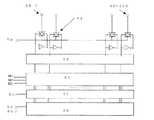
1 is a schematic perspective view of a mechanism part of an ink jet recording apparatus as a serial printer to which the present invention is applied, FIG. 2 is a cross-sectional view of a main part of the ink jet head of the recording apparatus, and FIG. 3 is an explanatory diagram of a nozzle pitch of the ink jet head. FIG. 4 is a principal block diagram of the control unit of the recording apparatus, and FIG. 5 is a block diagram showing an outline of functions of the host computer and the recording apparatus.
このインクジェット記録装置は、フレーム1に横架したガイドレール2,3にキャリッジ4を移動可能に装着し、このキャリッジ4に印字ヘッド5を搭載して、図示しないモータ等の駆動源によってキャリッジ4を矢示A方向に移動可能とすると共に、ガイド板6にセットされる被印字媒体である用紙(記録紙)7を、図示しない駆動源によってドライブギヤ8及びスプロケットギヤ9を介して回動される送りノブ10aを備えたプラテン10にて取込み、プラテン10周面とこれに圧接するプレッシャローラ11とによって矢示B方向に搬送可能としている。 In this ink jet recording apparatus, a
そして、このインクジェット記録装置では、印字ヘッド5(キャリッジ4)を主走査方向(矢示A方向)に移動走査させながら、用紙7を副走査方向(矢示B方向)に搬送して、印字ヘッド5からインク滴を噴射させて用紙7に画像を印字する。 In this inkjet recording apparatus, the print head 5 (carriage 4) is moved and scanned in the main scanning direction (arrow A direction) while the
キャリッジ4、印字ヘッド5、ならびにインク供給系等に関して、さらに詳細に説明する。
キャリッジ4にはイエロー(Y)、シアン(C)、マゼンタ(M)、ブラック(Bk)の各色のインク液滴を吐出するインクジェットヘッドからなる印字ヘッド5が具備され、そのヘッド5は複数のインク吐出口を主走査方向と交叉する方向に配列し、インク液滴の吐出方向を下方に向けて装着される。また、キャリッジ4には印字ヘッド5に各色のインクを供給するための各インクカートリッジを交換可能にして装着されている。The
The
インクカートリッジ15は上方に大気と連通する大気口、下方にはインクジェットヘッドへインクを供給する供給口を、内部にはインクが充填された多孔質体を有しており、多孔質体の毛管力によりインクジェットヘッドへ供給されるインクを僅かながら負圧して維持している。 The
また、本実施形態では、印字ヘッドとして各色個別構成のヘッドを用いて構成しているが、各色のインク液滴を吐出するノズル列を有する1個のヘッド構成としてもよい。さらに、インクを加圧してインク液滴を形成せしめる印字ヘッド(インクジェットヘッド)5としては、ピエゾ素子などの電気機械変換素子で液室壁面を形成し、振動板を介してインク加圧する圧電型若しくはインク流路壁面を形成する振動板とこれに対向する電極との間の静電気力で振動板を変位させてインク加圧する静電型などを使用することができるが、本実施形態では圧電型インクジェットヘッドを利用した場合について説明する。 Further, in this embodiment, the print head is configured using a head having an individual configuration of each color. However, a single head configuration having a nozzle array that ejects ink droplets of each color may be used. Further, as a print head (inkjet head) 5 that pressurizes ink to form ink droplets, a piezoelectric type in which a liquid chamber wall surface is formed by an electromechanical conversion element such as a piezo element and ink is pressurized via a vibration plate, or An electrostatic type that pressurizes ink by displacing the diaphragm by an electrostatic force between the diaphragm that forms the wall surface of the ink flow path and the electrode facing the diaphragm can be used. A case where the head is used will be described.
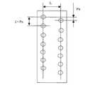
ここで、印字ヘッド5は、図2及び図3に示すように、液室14を形成する液室形成部材15の前面に複数のノズル16を形成したノズルプレート17が設けられ、図示しない圧電素子によるエネルギー発生手段であるアクチュエータによって液室14内のインクに圧力を与えることによって、液室14内のインクがノズルプレート17のノズル16からインク滴18となって飛翔して上記用紙7にドットとして付着する。このとき、各液室14に圧力を与えるアクチュエータを選択的に駆動することによって所望の画像の印字を行うことができる。 Here, as shown in FIGS. 2 and 3, the
この印字ヘッド5においては、複数のノズル16が複数のドット形成手段を構成しており、ノズル16の列(ノズル列)を主走査方向に対して直交させて配置し、ノズル16−16間のピッチは2×Pnである。また、1つのヘッドにはノズル列が距離L隔てて2列形成されている。2列のノズル列は副走査方向にPnずれて千鳥状に配置され、2列のノズル列を用いることで、ピッチPnの画像を1回の主走査及び副走査で形成することが可能である。 In this
また、キャリッジ4を主走査方向に移動走査させるため、主走査モータで回転駆動される駆動プーリと従動プーリとの間をタイミングベルトにより張装し、このタイミングベルトをキャリッジに固定することで、主走査モーターの正逆回転に応じてキャリッジが往復移動される。 Further, in order to move and scan the
一方、ガイド板にセットした用紙を印字ヘッドの印写部に搬送するために、ガイド板から、用紙を給装する給紙ローラ及びフリクションパッドと、用紙を案内するガイド部材と、給紙された用紙を搬送する搬送ローラと、この搬送ローラの周面に押し付けられる搬送コロ及び搬送ローラからの用紙の送り出し角度を規定する先端コロとを設けている。搬送ローラは副走査モータによってギヤ列を介して回転駆動される。そして、キャリッジの主走査方向の移動範囲に対応して搬送ローラから送り出された用紙を印字ヘッドの印写部まで案内(ガイド)するために、プラテンローラを配置している。更に、印写受け部材の用紙搬送方向下流側には、用紙を排紙方向へ送り出すために回転駆動される搬送コロ、及び拍車とを設け、さらに用紙を排紙トレイに送り出すための排紙ローラ、及び拍車と、排紙経路を確保するためのガイド部材等を配設している。 On the other hand, in order to convey the paper set on the guide plate to the printing section of the print head, the paper is fed from the guide plate to the paper feed roller and friction pad for feeding the paper, the guide member for guiding the paper, A conveyance roller that conveys the sheet, a conveyance roller that is pressed against the peripheral surface of the conveyance roller, and a leading end roller that defines a feeding angle of the sheet from the conveyance roller are provided. The transport roller is rotationally driven through a gear train by a sub-scanning motor. A platen roller is arranged to guide (guide) the paper fed from the transport roller to the printing portion of the print head in accordance with the movement range of the carriage in the main scanning direction. Further, on the downstream side of the printing receiving member in the paper conveyance direction, a conveyance roller that is rotationally driven to send the paper in the paper discharge direction and a spur are provided, and a paper discharge roller for sending the paper to the paper discharge tray , And a spur and a guide member for securing a paper discharge path are disposed.
印刷時には、キャリッジ4を移動させながら画像信号に応じて印字ヘッドを駆動させる。停止している用紙にインクを吐出して1行分を印字し、用紙を所定量搬送後、次の行の印字を行う。印刷終了時には、印字終了信号、または、用紙の後端が印字領域に到達した信号を受け取ることにより、印字動作を終了させて用紙が排紙される。 During printing, the print head is driven according to the image signal while moving the
また、キャリッジの移動方向右端側の印字領域を外れた位置には、印字ヘッドの吐出不良を回復するための図示しない回復処理装置を配置している。回復処理装置にはキャップ手段と吸引手段とクリーニング手段とを有している。キャリッジは印字待機中にはこの回復処理装置側に移動されてキャッピング手段でヘッドがキャッピングされ、吐出口部を湿潤状態に保つことによりインク乾燥によるインク吐出不良を防ぐことができる。また、印字途中などに印字と関係しないインクを吐出することで、全ての吐出口内のインク粘度が一定となり、安定した吐出性能が維持される。吐出不良が発生した場合等には、キャッピング手段でヘッドの吐出口を密封し、チューブを通して吸引手段で吐出口からインクとともに気泡等を吸い出し、吐出口面に付着したインクやゴミ等はクリーニング手段により除去され吐出不良が回復される。また、吸引されたインクは、本体下部に設置された廃インク溜(不図示)に排出され、廃インク溜内部のインク吸収体に吸収保持される。 Further, a recovery processing device (not shown) for recovering the ejection failure of the print head is disposed at a position outside the print area on the right end side in the carriage movement direction. The recovery processing apparatus has a cap unit, a suction unit, and a cleaning unit. The carriage is moved to the recovery processing apparatus side during printing standby, the head is capped by the capping means, and ink discharge defects due to ink drying can be prevented by keeping the discharge port portion in a wet state. Further, by ejecting ink not related to printing during printing or the like, the ink viscosity in all the ejection ports becomes constant, and stable ejection performance is maintained. If a discharge failure occurs, seal the discharge port of the head with a capping device, suck out bubbles and the like from the discharge port with the suction device through the tube, and remove ink and dust adhering to the discharge port surface with the cleaning device. Removal and ejection failure are recovered. Further, the sucked ink is discharged to a waste ink reservoir (not shown) installed at the lower part of the main body and absorbed and held by an ink absorber inside the waste ink reservoir.
本実施形態の記録装置では装置内に画像の描画または文字のプリント命令を受けて実際に記録するドットパターンを発生する機能を持たない例を示す。即ち、ホストコンピュータで実行されるアプリケーションソフトなどからのプリント命令はホストコンピュータ内にソフトウェアとして組み込まれたプリントドライバで処理されて記録ドットパターンのデータにラスタライズされ、それが記録装置に転送されてプリントされる。 The recording apparatus according to the present embodiment shows an example in which the apparatus does not have a function of generating a dot pattern that is actually recorded in response to an image drawing or character print command. That is, a print command from application software executed on the host computer is processed by a print driver incorporated as software in the host computer, rasterized into recording dot pattern data, transferred to the recording device, and printed. The
具体的には、ホストコンピュータ内のアプリケーションやオペレーティングシステムからの画像の描画または文字の記録命令(例えば記録する線の位置と太さと形などを記述したものや、記録する文字の書体と大きさと位置などを記述したもの)は描画データメモリに一時的に保存さる。尚、これらの命令は、特定のプリント言語で記述されたものである。 Specifically, an image drawing or character recording command from an application or operating system in the host computer (for example, a description of the position, thickness and shape of a line to be recorded, or the typeface, size and position of a character to be recorded) Etc.) are temporarily stored in the drawing data memory. Note that these instructions are written in a specific print language.
描画データメモリに記憶された命令は、ラスタライザによって解釈され、線の記録命令であれば、指定された位置や太さ等に応じた記録ドットパターンに変換され、また、文字の記録命令であればホストコンピュータ内に保存されているフォントアウトラインデータから対応する文字の輪郭情報を呼びだし指定された位置や大きさに応じてた記録ドットパターンに変換されてラスタデータメモリに記憶される。このとき、ホストコンピュータは、従来の直交格子を基本記録位置として、記録ドットパターンのデータにラスタライズする。このラスタデータメモリに記憶された記録ドットパターンがインターフェースを経由してインクジェット記録装置へ転送されるものである。 The command stored in the drawing data memory is interpreted by the rasterizer, and if it is a line recording command, it is converted into a recording dot pattern according to the specified position, thickness, etc., and if it is a character recording command The outline information of the corresponding character is called from the font outline data stored in the host computer, converted into a recording dot pattern corresponding to the designated position and size, and stored in the raster data memory. At this time, the host computer uses the conventional orthogonal grid as a basic recording position and rasterizes it into recording dot pattern data. The recording dot pattern stored in the raster data memory is transferred to the ink jet recording apparatus via the interface.
インクジェット記録装置の制御部は、図4に示すように印字制御部23、印字ヘッド5の各アクチュエータを駆動するヘッド駆動部24、キャリッジ4を駆動制御するキャリッジ駆動制御部25、プラテン10を回転駆動するラインフィード駆動制御部16、データ処理部27等からなる。 As shown in FIG. 4, the control unit of the ink jet recording apparatus rotates the
ホストコンピュータから送られた印字データは、図示しないラスタデータメモリーに保存され、所定のデータを受け取った後に、データ処理部27を介して、印字ドットデータに基づいてヘッド駆動部24を介して印字ヘッド5の所定のノズル孔16からインク滴を吐出(噴射)させて印字データに応じた画像を用紙7上に記録させると共に、キャリッジ駆動制御部25を介してキャリッジ4の移動(主走査)及びラインフィード駆動制御部16を介してプラテン10の回動、即ち用紙7の搬送(副走査)を制御する。 The print data sent from the host computer is stored in a raster data memory (not shown), and after receiving predetermined data, the print head passes through the
ここで、従来のインクジェット記録装置で、特に普通紙上に印字した場合には、画像の色再現性、耐久性、耐光性、インク乾燥性、文字滲み(フェザリング)、色境界滲み(カラーブリード)、両面印刷性等、インクジェット記録装置特有の画質劣化問題が顕在しており、更に、普通紙にて高速印字しようとした場合には、これら全ての特性を満足して印刷することは極めて難しい課題となっていた。 Here, when printing on plain paper with a conventional inkjet recording apparatus, color reproducibility, durability, light resistance, ink drying, character bleeding (feathering), color boundary bleeding (color bleeding) In addition, image quality degradation problems peculiar to inkjet recording devices such as double-sided printability have been revealed, and when trying to print at high speed on plain paper, it is extremely difficult to print satisfying all these characteristics It was.
また、通常、インクジェット印刷に使用されるインクは、水を主成分とし、これに着色剤、及び目詰まり防止等の目的でグリセリン等の湿潤剤を含有したものが一般的である。着色剤としては、染料と顔料とがあり、優れた発色性や安定性が得られる点からカラー色部には従来より染料系インクが用いられる場合が多い。しかし、染料系インクを用いて得られる画像の耐光性、耐水性等の堅牢性は着色剤に顔料を利用したものに対して劣るものであり、特に、耐水性については、インク吸収層を有するインクジェット専用記録紙を使用すれば、ある程度の改善を図ることは可能となるが、普通紙を使用した場合には満足の得られるものとはなっていないのが一般的である。 In general, an ink used for ink jet printing generally contains water as a main component and contains a colorant and a wetting agent such as glycerin for the purpose of preventing clogging. As the colorant, there are a dye and a pigment, and a dye-based ink is often used for the color portion from the point that excellent color developability and stability can be obtained. However, fastness such as light resistance and water resistance of an image obtained using a dye-based ink is inferior to that using a pigment as a colorant, and in particular, the water resistance has an ink absorption layer. If ink jet recording paper is used, it is possible to achieve a certain degree of improvement. However, when plain paper is used, it is generally not satisfactory.
そこで近年、普通紙を使用した場合での上記染料系インクに対する問題点を改善するために、着色剤として有機顔料、カーボンブラック等を用いる顔料系インクの使用が普通紙印字に対して検討、あるいは実用化がされている。顔料は染料とは異なり水への溶解性がないため、通常は、顔料を分散剤とともに混合し、分散処理して水に安定分散させた状態の水性インクとして用いられる。 Therefore, in recent years, the use of pigment-based inks using organic pigments, carbon black, etc. as colorants has been studied for printing on plain paper, in order to improve the problems associated with the dye-based inks when using plain paper, or It has been put to practical use. Since pigments are not soluble in water unlike dyes, they are usually used as water-based inks in a state where pigments are mixed with a dispersing agent, dispersed and stably dispersed in water.
一般に、顔料を用いることで、耐光性や耐水性の向上は得られるものの、他の画質特性とを同時に満足することは難しく、特に、普通紙に高速印字しようとした場合には高い画像濃度、十分な発色性、色再現性等を得ることが困難で、文字滲み、色境界滲み、両面印刷性、インク乾燥性(定着性)等も十分に満足の得られるものとはなっていない点が未だあった。 In general, using pigments can improve light resistance and water resistance, but it is difficult to satisfy other image quality characteristics at the same time, especially when trying to print on plain paper at high speed, It is difficult to obtain sufficient color developability, color reproducibility, etc., and character bleeding, color boundary bleeding, double-sided printing properties, ink drying properties (fixability), etc. are not sufficiently satisfactory. It was still there.
ここで、本発明で使用されるインク液滴の構成について説明を行う。本発明で用いられるインク液滴は、次の下記構成よりなる印字用インクを使用するものである。すなわち、印字するための着色剤として顔料を使用し、それを分解、分散させるための溶剤とを必須成分とし、更に添加剤として、湿潤剤、界面活性剤、エマルジョン、防腐剤、pH調整剤とを使用する。湿潤剤1と湿潤剤2とを混合するのは各々湿潤剤の特徴を活かすためと、粘度調整が容易にできるためである。
(1) 顔料(自己分散性顔料)6wt%以上
(2) 湿潤剤1
(3) 湿潤剤2
(4) 水溶性有機溶剤
(5) アニオンまたはノニオン系界面活性剤
(6) 炭素数8以上のポリオールまたはグリコールエーテル
(7) エマルジョン
(8) 防腐剤
(9) pH調製剤
(10) 純水Here, the configuration of the ink droplets used in the present invention will be described. The ink droplet used in the present invention uses a printing ink having the following configuration. That is, a pigment is used as a colorant for printing, a solvent for decomposing and dispersing it is an essential component, and further additives are a wetting agent, a surfactant, an emulsion, an antiseptic, a pH adjuster, Is used. The reason why the
(1) Pigment (self-dispersing pigment) 6 wt% or more (2)
(3)
(4) Water-soluble organic solvent (5) Anion or nonionic surfactant (6) Polyol or glycol ether having 8 or more carbon atoms (7) Emulsion (8) Preservative (9) pH adjuster (10) Pure water
以下、本発明に用いられる上記各インク構成要素について、より具体的に説明を行う。
(1)の顔料に関しては、特にその種類を限定することなく、無機顔料、有機顔料を使用することができる。無機顔料としては、酸化チタン及び酸化鉄に加え、コンタクト法、ファーネス法、サーマル法などの公知の方法によって製造されたカーボンブラックを使用することができる。また、有機顔料としては、アゾ顔料(アゾレーキ、不溶性アゾ顔料、縮合アゾ顔料、キレートアゾ顔料などを含む)、多環式顔料(例えば、フタロシアニン顔料、ぺリレン顔料、ぺリノン顔料、アントラキノン顔料、キナクリドン顔料、ジオキサジン顔料、チオインジゴ顔料、イソインドリノン顔料、キノフラロン顔料など)、染料キレート(例えば、塩基性染料型キレート、酸性染料型キレートなど)、ニトロ顔料、ニトロソ顔料、アニリンブラックなどを使用できる。Hereinafter, each of the ink components used in the present invention will be described more specifically.
Regarding the pigment of (1), inorganic pigments and organic pigments can be used without any particular limitation. As the inorganic pigment, in addition to titanium oxide and iron oxide, carbon black produced by a known method such as a contact method, a furnace method, or a thermal method can be used. Organic pigments include azo pigments (including azo lakes, insoluble azo pigments, condensed azo pigments, chelate azo pigments), polycyclic pigments (for example, phthalocyanine pigments, perylene pigments, perinone pigments, anthraquinone pigments, quinacridone pigments). , Dioxazine pigments, thioindigo pigments, isoindolinone pigments, quinofullerone pigments, etc.), dye chelates (for example, basic dye type chelates, acidic dye type chelates), nitro pigments, nitroso pigments, aniline black, and the like.
本発明の好ましい態様によれば、これらの顔料のうち、水と親和性の良いものが好ましく用いられる。顔料の粒径は、0.05μmから10μm以下が好ましく、さらに好ましくは1μm以下であり、最も好ましくは0.16μm以下である。
インク中の着色剤としての顔料の添加量は、6〜20重量%程度が好ましく、より好ましくは8〜12重量%程度である。According to a preferred embodiment of the present invention, among these pigments, those having a good affinity for water are preferably used. The particle diameter of the pigment is preferably 0.05 μm to 10 μm, more preferably 1 μm or less, and most preferably 0.16 μm or less.
The amount of pigment added as a colorant in the ink is preferably about 6 to 20% by weight, more preferably about 8 to 12% by weight.
本発明において好ましく用いられる顔料の具体例としては、以下のものが挙げられる。
黒色用としては、ファーネスブラック、ランプブラック、アセチレンブラック、チャンネルブラック等のカーボンブラック(C.I.ピグメントブラック7)類、または銅、鉄(C.I.ピグメントブラック11)、酸化チタン等の金属類、アニリンブラック(C.I.ピグメントブラック1)等の有機顔料があげられる。Specific examples of the pigment preferably used in the present invention include the following.
For black, carbon black (CI Pigment Black 7) such as furnace black, lamp black, acetylene black, channel black, or metal such as copper, iron (CI Pigment Black 11), titanium oxide And organic pigments such as aniline black (CI Pigment Black 1).
さらに、カラー用としては、C.I.ピグメントイエロー1(ファストイエローG)、3、12(ジスアゾイエローAAA)、13、14、17、24、34、35、37、42(黄色酸化鉄)、53、55、81、83(ジスアゾイエローHR)、95、97、98、100、101、104、408、109、110、117、120、138、153、C.I.ピグメントオレンジ5、13、16、17、36、43、51、C.I.ピグメントレッド1、2、3、5、17、22(ブリリアントファーストスカレット)、23、31、38、48:2(パーマネントレッド2B(Ba))、48:2(パーマネントレッド2B(Ca))、48:3(パーマネントレッド2B(Sr))、48:4(パーマネントレッド2B(Mn))、49:1、52:2、53:1、57:1(ブリリアントカーミン6B)、60:1、63:1、63:2、64:1、81(ローダミン6Gレーキ)、83、88、101(べんがら)、104、105、106、108(カドミウムレッド)、112、114、122(キナクリドンマゼンタ)、123、146、149、166、168、170、172、177、178、179、185、190、193、209、219、C.I.ピグメントバイオレット1(ローダミンレーキ)、3、5:1、16、19、23、38、C.I.ピグメントブルー1、2、15(フタロシアニンブルーR)、15:1、15:2、15:3(フタロシアニンブルーE)、16、17:1、56、60、63、C.I.ピグメントグリーン1、4、7、8、10、17、18、36等がある。 Further, for color use, C.I. I. Pigment Yellow 1 (Fast Yellow G), 3, 12 (Disazo Yellow AAA), 13, 14, 17, 24, 34, 35, 37, 42 (Yellow Iron Oxide), 53, 55, 81, 83 (Disazo Yellow HR) ), 95, 97, 98, 100, 101, 104, 408, 109, 110, 117, 120, 138, 153, C.I. I.
その他顔料(例えばカーボン)の表面を樹脂等で処理し、水中に分散可能としたグラフト顔料や、顔料(例えばカーボン)の表面にスルホン基やカルボキシル基等の官能基を付加し水中に分散可能とした加工顔料等が使用できる。
また、顔料をマイクロカプセルに包含させ、該顔料を水中に分散可能なものとしたものであっても良い。Other pigment pigments (eg carbon) treated with resin, etc., can be dispersed in water, and pigments (eg carbon) can be dispersed in water by adding functional groups such as sulfone groups and carboxyl groups to the surface. Processed pigments can be used.
Further, a pigment may be included in a microcapsule so that the pigment can be dispersed in water.
本発明の好ましい態様によれば、ブラックインク用の顔料は、顔料を分散剤で水性媒体中に分散させて得られた顔料分散液としてインクに添加されるのが好ましい。好ましい分散剤としては、従来公知の顔料分散液を調整するのに用いられる公知の分散液を使用することができる。 According to a preferred embodiment of the present invention, the pigment for black ink is preferably added to the ink as a pigment dispersion obtained by dispersing the pigment in an aqueous medium with a dispersant. As a preferable dispersing agent, a known dispersion used for preparing a conventionally known pigment dispersion can be used.
分散液としては、例えば以下のものが挙げられる。
ポリアクリル酸、ポリメタクリル酸、アクリル酸−アクリロニトリル共重合体、酢酸ビニル−アクリル酸エステル共重合体、アクリル酸−アクリル酸アルキルエステル共重合体、スチレン−アクリル酸共重合体、スチレン−メタクリル酸共重合体、スチレン−アクリル酸−アクリル酸アルキルエステル共重合体、スチレン−メタクリル酸−アクリル酸アルキルエステル共重合体、スチレン−α−メチルスチレン−アクリル酸共重合体、スチレン−α−メチルスチレン−アクリル酸共重合体−アクリル酸アルキルエステル共重合体、スチレン−マレイン酸共重合体、ビニルナフタレン−マレイン酸共重合体、酢酸ビニル−エチレン共重合体、酢酸ビニル−脂肪酸ビニルエチレン共重合体、酢酸ビニル−マレイン酸エステル共重合体、酢酸ビニル−クロトン酸共重合体、酢酸ビニル−アクリル酸共重合体等が挙げられる。Examples of the dispersion include the following.
Polyacrylic acid, polymethacrylic acid, acrylic acid-acrylonitrile copolymer, vinyl acetate-acrylic acid ester copolymer, acrylic acid-acrylic acid alkyl ester copolymer, styrene-acrylic acid copolymer, styrene-methacrylic acid copolymer Polymer, styrene-acrylic acid-alkyl acrylate ester copolymer, styrene-methacrylic acid-alkyl acrylate copolymer, styrene-α-methylstyrene-acrylic acid copolymer, styrene-α-methylstyrene-acrylic Acid copolymer-alkyl acrylate ester copolymer, styrene-maleic acid copolymer, vinyl naphthalene-maleic acid copolymer, vinyl acetate-ethylene copolymer, vinyl acetate-fatty acid vinyl ethylene copolymer, vinyl acetate -Maleate ester copolymer, vinyl acetate- Examples include crotonic acid copolymers and vinyl acetate-acrylic acid copolymers.
本発明の好ましい態様によれば、これらの共重合体は重量平均分子量が3,000〜50,000であるのが好ましく、より好ましくは5,000〜30,000、最も好ましくは7,000〜15,000である。分散剤の添加量は、顔料を安定に分散させ、本発明の他の効果を失わせない範囲で適宣添加されて良い。分散剤としては1:0.06〜1:3の範囲が好ましく、より好ましくは1:0.125〜1:3の範囲である。 According to a preferred embodiment of the present invention, these copolymers preferably have a weight average molecular weight of 3,000 to 50,000, more preferably 5,000 to 30,000, most preferably 7,000 to 7,000. 15,000. The addition amount of the dispersant may be appropriately added as long as the pigment is stably dispersed and the other effects of the present invention are not lost. The dispersant is preferably in the range of 1: 0.06 to 1: 3, more preferably in the range of 1: 0.125 to 1: 3.
着色剤に使用する顔料は、記録用インク全重量に対して6重量%〜20重量%含有し、0.05μm〜0.16μm以下の粒子径の粒子であり、分散剤により水中に分散されていて、分散剤が、分子量5,000から100,000の高分子分散剤である。水溶性有機溶剤が少なくとも1種類にピロリドン誘導体、特に、2−ピロリドンを使用すると画像品質が向上する。 The pigment used for the colorant is a particle having a particle size of 0.05 to 0.16 μm, containing 6 to 20% by weight based on the total weight of the recording ink, and is dispersed in water by a dispersant. The dispersant is a polymer dispersant having a molecular weight of 5,000 to 100,000. When at least one water-soluble organic solvent is a pyrrolidone derivative, particularly 2-pyrrolidone, the image quality is improved.
(2)〜(4)の湿潤剤1・2と、水溶性有機溶剤に関しては、本発明の場合、インク中に水を液媒体として使用するものであるが、インクを所望の物性にし、インクの乾燥を防止するために、また、溶解安定性を向上するため等の目的で、例えば下記の水溶性有機溶剤が使用される。これら水溶性有機溶剤は複数混合して使用してもよい。湿潤剤と水溶性有機溶剤の具体例としては、例えば以下のものが挙げられる。 Regarding the
エチレングリコール、ジエチレングリコール、トリエチレングリコール、プロピレングリコール、ジプロピレングリコール、トリプロピレングリコール、テトラエチレングリコール、ヘキシレングリコール、ポリエチレングリコール、ポリプロピレングリコール、1,5−ペンタンジオール、1,6−ヘキサンジオール、グリセロール、1,2,6−ヘキサントリオール、1,2,4−ブタントリオール、1,2,3−ブタントリオール、ペトリオール等の多価アルコール類;エチレングリコールモノエチルエーテル、エチレングリコールモノブチルエーテル、ジエチレングリコールモノメチルエーテル、ジエチレングリコールモノエチルエーテル、ジエチレングリコールモノブチルエーテル、テトラエチレングリコールモノメチルエーテル、プロピレングリコールモノエチルエーテル等の多価アルコールアルキルエーテル類;エチレングリコールモノフェニルエーテル、エチレングリコールモノベンジルエーテル等の多価アルコールアリールエーテル類;2−ピロリドン、N−メチル−2−ピロリドン、N−ヒドロキシエチル−2−ピロリドン、1,3−ジメチルイミイダゾリジノン、ε−カプロラクタム、γ−ブチロラクトン等の含窒素複素環化合物;ホルムアミド、N−メチルホルムアミド、N,N−ジメチルホルムアミド等のアミド類;モノエタノールアミン、ジエタノールアミン、トリエタノールアミン、モノエチルアミン、ジエチルアミン、トリエチルアミン等のアミン類;ジメチルスルホキシド、スルホラン、チオジエタノール等の含硫黄化合物類;プロピレンカーボネート、炭酸エチレン等である。 Ethylene glycol, diethylene glycol, triethylene glycol, propylene glycol, dipropylene glycol, tripropylene glycol, tetraethylene glycol, hexylene glycol, polyethylene glycol, polypropylene glycol, 1,5-pentanediol, 1,6-hexanediol, glycerol, Polyhydric alcohols such as 1,2,6-hexanetriol, 1,2,4-butanetriol, 1,2,3-butanetriol, petriol; ethylene glycol monoethyl ether, ethylene glycol monobutyl ether, diethylene glycol monomethyl ether , Diethylene glycol monoethyl ether, diethylene glycol monobutyl ether, tetraethylene glycol monomethyl ether Polyhydric alcohol alkyl ethers such as propylene glycol monoethyl ether; Polyhydric alcohol aryl ethers such as ethylene glycol monophenyl ether and ethylene glycol monobenzyl ether; 2-pyrrolidone, N-methyl-2-pyrrolidone, N-hydroxyethyl Nitrogen-containing heterocyclic compounds such as 2-pyrrolidone, 1,3-dimethylimidazolidinone, ε-caprolactam, γ-butyrolactone; amides such as formamide, N-methylformamide, N, N-dimethylformamide; monoethanol Amines such as amine, diethanolamine, triethanolamine, monoethylamine, diethylamine and triethylamine; sulfur-containing compounds such as dimethyl sulfoxide, sulfolane and thiodiethanol; propylene carbonate Over bets is ethylene carbonate.
これら有機溶媒の中でも、特にジエチレングリコール、チオジエタノール、ポリエチレングリコール200〜600、トリエチレングリコール、グリセロール、1,2,6−ヘキサントリオール、1,2,4−ブタントリオール、ペトリオール、1,5−ペンタンジオール、2−ピロリドン、N−メチル−2−ピロリドンが好ましい。これらは溶解性と水分蒸発による噴射特性不良の防止に対して優れた効果が得られる。 Among these organic solvents, diethylene glycol, thiodiethanol, polyethylene glycol 200 to 600, triethylene glycol, glycerol, 1,2,6-hexanetriol, 1,2,4-butanetriol, petriol, 1,5-pentane Diol, 2-pyrrolidone and N-methyl-2-pyrrolidone are preferred. These are excellent in solubility and prevention of poor jetting characteristics due to water evaporation.
その他の湿潤剤としては、糖を含有してなるのが好ましい。糖類の例としては、単糖類、二糖類、オリゴ糖類(三糖類および四糖類を含む)および多糖類があげられ、好ましくはグルコース、マンノース、フルクトース、リボース、キシロース、アラビノース、ガラクトース、マルトース、セロビオース、ラクトース、スクロース、トレハロース、マルトトリオースなどがあげられる。ここで、多糖類とは広義の糖を意味し、α−シクロデキストリン、セルロースなど自然界に広く存在する物質を含む意味に用いることとする。 The other wetting agent preferably contains sugar. Examples of saccharides include monosaccharides, disaccharides, oligosaccharides (including trisaccharides and tetrasaccharides) and polysaccharides, preferably glucose, mannose, fructose, ribose, xylose, arabinose, galactose, maltose, cellobiose, Examples include lactose, sucrose, trehalose and maltotriose. Here, the polysaccharide means a saccharide in a broad sense, and is used to include a substance that exists widely in nature such as α-cyclodextrin and cellulose.
また、これらの糖類の誘導体としては、上記した糖類の還元糖(例えば、糖アルコール(一般式HOCH2(CHOH)nCH2OH(ここでn=2〜5の整数を表す。)で表される。)、酸化糖(例えば、アルドン酸、ウロン酸など)、アミノ酸、チオ酸などがあげられる。特に糖アルコールが好ましく、具体例としてはマルチトール、ソルビットなどがあげられる。
これら糖類の含有量は、インク組成物の0.1〜40重量%、好ましくは0.5〜30重量%の範囲が適当である。Moreover, as a derivative | guide_body of these saccharides, the reducing saccharide | sugar of said saccharide | sugar (For example, sugar alcohol (It represents with the general formula HOCH2 (CHOH) nCH2OH (here n represents the integer of 2-5))). Oxidized sugars (for example, aldonic acid, uronic acid, etc.), amino acids, thioic acids, etc. Particularly preferred are sugar alcohols, and specific examples include maltitol, sorbit and the like.
The content of these saccharides is suitably 0.1 to 40% by weight, preferably 0.5 to 30% by weight of the ink composition.
(5)の界面活性剤に関しても、特に限定はされないが、アニオン性界面活性剤としては、例えばポリオキシエチレンアルキルエーテル酢酸塩、ドデシルベンゼンスルホン酸塩、ラウリル酸塩、ポリオキシエチレンアルキルエーテルサルフェートの塩などが挙げられる。 The surfactant (5) is not particularly limited, but examples of the anionic surfactant include polyoxyethylene alkyl ether acetate, dodecylbenzene sulfonate, laurate, and polyoxyethylene alkyl ether sulfate. Examples include salt.
非イオン性界面活性剤としては、例えば、ポリオキシエチレンアルキルエーテル、ポリオキシエチレンアルキルエステル、ポリオキシエチレンソルビタン脂肪酸エステル、ポリオキシエチレンアルキルフェニルエーテル、ポリオキシエチレンアルキルアミン、ポリオキシエチレンアルキルアミドなどが挙げられる。上記界面活性剤は、単独または二種以上を混合して用いることができる。 Nonionic surfactants include, for example, polyoxyethylene alkyl ethers, polyoxyethylene alkyl esters, polyoxyethylene sorbitan fatty acid esters, polyoxyethylene alkyl phenyl ethers, polyoxyethylene alkyl amines, polyoxyethylene alkyl amides, and the like. Can be mentioned. The said surfactant can be used individually or in mixture of 2 or more types.
本発明における表面張力は紙への浸透性を示す指標であり、特に表面形成されて1秒以下の短い時間での動的表面張力を示し、飽和時間で測定される静的表面張力とは異なる。測定法としては特開昭63−31237号公報等に記載の従来公知の方法で1秒以下の動的な表面張力を測定できる方法であればいずれも使用できるが本発明ではWilhelmy式の吊り板式表面張力計を用いて測定した。表面張力の値は40mJ/m2以下が好ましく、より好ましくは35mJ/m2以下とすると優れた定着性と乾燥性が得られる。 The surface tension in the present invention is an index indicating the permeability to paper. In particular, the surface tension indicates the dynamic surface tension in a short time of 1 second or less after the surface is formed, and is different from the static surface tension measured by the saturation time. . Any method can be used as long as it can measure a dynamic surface tension of 1 second or less by a conventionally known method described in JP-A-63-31237 or the like. In the present invention, a Wilhelmy type suspension plate type is used. It measured using the surface tension meter. When the value of the surface tension is preferably 40 mJ /
(6)の炭素数8以上のポリオールまたはグリコールエーテルに関しては、25℃の水中において0.1〜4.5重量%未満の間の溶解度を有する部分的に水溶性のポリオールおよび/またはグリコールエーテルを記録用インク全重量に対してを0.1〜10.0重量%添加することによって、該インクの熱素子への濡れ性が改良され、少量の添加量でも吐出安定性および周波数安定性が得られることが分かった。
(6−1) 2−エチル−1,3−ヘキサンジオール 溶解度:4.2%(20℃)
(6−2) 2,2,4−トリメチル−1,3−ペンタンジオール 溶解度:2.0%(25℃)For (6) polyols or glycol ethers having 8 or more carbon atoms, partially water-soluble polyols and / or glycol ethers having a solubility of less than 0.1 to 4.5% by weight in water at 25 ° C. By adding 0.1 to 10.0% by weight with respect to the total weight of the recording ink, the wettability of the ink to the thermal element is improved, and ejection stability and frequency stability can be obtained even with a small addition amount. I found out that
(6-1) 2-ethyl-1,3-hexanediol Solubility: 4.2% (20 ° C.)
(6-2) 2,2,4-Trimethyl-1,3-pentanediol Solubility: 2.0% (25 ° C.)
25℃の水中において0.1〜4.5重量%未満の間の溶解度を有する浸透剤は溶解度が低い代わりに浸透性が非常に高いという長所がある。従って、25℃の水中において0.1〜4.5重量%未満の間の溶解度を有する浸透剤と他の溶剤との組み合わせや他の界面活性剤との組み合わせで非常に高浸透性のあるインクを作製することが可能となる。 A penetrant having a solubility of less than 0.1-4.5% by weight in water at 25 ° C. has the advantage of very high permeability instead of low solubility. Therefore, an ink having a very high permeability in a combination of a penetrant having a solubility of less than 0.1 to 4.5% by weight in water at 25 ° C. with another solvent or another surfactant. Can be produced.
(7)本発明のインクには樹脂エマルジョンが添加されている方が好ましい。
樹脂エマルジョンとは、連続相が水であり、分散相が次の様な樹脂成分であるエマルジョンを意味する。分散相の樹脂成分としてはアクリル系樹脂、酢酸ビニル系樹脂、スチレン−ブタジエン系樹脂、塩化ビニル系樹脂、アクリル−スチレン系樹脂、ブタジエン系樹脂、スチレン系樹脂などがあげられる。(7) It is preferable that a resin emulsion is added to the ink of the present invention.
The resin emulsion means an emulsion in which the continuous phase is water and the dispersed phase is the following resin component. Examples of the resin component in the dispersed phase include acrylic resins, vinyl acetate resins, styrene-butadiene resins, vinyl chloride resins, acrylic-styrene resins, butadiene resins, and styrene resins.
本発明の好ましい態様によれば、この樹脂は親水性部分と疎水性部分とを併せ持つ重合体であるのが好ましい。また、これらの樹脂成分の粒子径はエマルジョンを形成する限り特に限定されないが、150nm程度以下が好ましく、より好ましくは5〜100nm程度である。
これらの樹脂エマルジョンは、樹脂粒子を、場合によって界面活性剤とともに水に混合することによって得ることができる。According to a preferred embodiment of the present invention, the resin is preferably a polymer having both a hydrophilic part and a hydrophobic part. The particle size of these resin components is not particularly limited as long as an emulsion is formed, but is preferably about 150 nm or less, more preferably about 5 to 100 nm.
These resin emulsions can be obtained by mixing resin particles in water, optionally with a surfactant.
例えば、アクリル系樹脂またはスチレン−アクリル系樹脂のエマルジョンは、(メタ)アクリル酸エステルまたはスチレンと、(メタ)アクリル酸エステルと、場合により(メタ)アクリル酸エステルと、界面活性剤とを水に混合することによって得ることができる。樹脂成分と界面活性剤との混合の割合は、通常10:1〜5:1程度とするのが好ましい。界面活性剤の使用量が上記範囲に満たない場合、エマルジョンとなりにくく、また上記範囲を超える場合、インクの耐水性が低下したり、浸透性が悪化する傾向があるので好ましくない。 For example, an acrylic resin or styrene-acrylic resin emulsion can be obtained by adding (meth) acrylic acid ester or styrene, (meth) acrylic acid ester, and optionally (meth) acrylic acid ester, and a surfactant to water. It can be obtained by mixing. The mixing ratio of the resin component and the surfactant is usually preferably about 10: 1 to 5: 1. When the amount of the surfactant used is less than the above range, it is difficult to form an emulsion, and when it exceeds the above range, the water resistance of the ink tends to decrease or the permeability tends to deteriorate, such being undesirable.
上記エマルジョンの分散相成分としての樹脂と水との割合は、樹脂100重量部に対して水60〜400重量部、好ましくは100〜200の範囲が適当である。
市販の樹脂エマルジョンとしては、マイクロジェルE−1002、E−5002(スチレン−アクリル系樹脂エマルジョン、日本ペイント株式会社製)、ボンコート4001(アクリル系樹脂エマルジョン、大日本インキ化学工業株式会社製)、ボンコート5454(スチレン−アクリル系樹脂エマルジョン、大日本インキ化学工業株式会社製)、SAE−1014(スチレン−アクリル系樹脂エマルジョン、日本ゼオン株式会社製)、サイビノールSK−200(アクリル系樹脂エマルジョン、サイデン化学株式会社製)、などがあげられる。The ratio of the resin and water as the dispersed phase component of the emulsion is 60 to 400 parts by weight, preferably 100 to 200 parts by weight with respect to 100 parts by weight of the resin.
Commercially available resin emulsions include Microgel E-1002, E-5002 (styrene-acrylic resin emulsion, manufactured by Nippon Paint Co., Ltd.), Boncoat 4001 (acrylic resin emulsion, manufactured by Dainippon Ink and Chemicals, Inc.), Boncoat 5454 (styrene-acrylic resin emulsion, manufactured by Dainippon Ink & Chemicals, Inc.), SAE-1014 (styrene-acrylic resin emulsion, manufactured by Nippon Zeon Co., Ltd.), Cybinol SK-200 (acrylic resin emulsion, Seiden Chemical Co., Ltd.) Etc.).
本発明に使用するインクは、樹脂エマルジョンを、その樹脂成分がインクの0.1〜40重量%となるよう含有するのが好ましく、より好ましくは1〜25重量%の範囲である。
樹脂エマルジョンは、増粘・凝集する性質を持ち、着色成分の浸透を抑制し、さらに記録材への定着を促進する効果を有する。また、樹脂エマルジョンの種類によっては記録材上で皮膜を形成し、印刷物の耐擦性をも向上させる効果を有する。The ink used in the present invention preferably contains a resin emulsion such that the resin component is 0.1 to 40% by weight of the ink, more preferably 1 to 25% by weight.
The resin emulsion has the property of thickening and aggregating, has the effect of suppressing the penetration of the coloring components, and further promoting the fixing to the recording material. Further, depending on the type of resin emulsion, a film is formed on the recording material, and the printed material has an effect of improving the abrasion resistance.
(8)〜(10)本発明のインクには上記着色剤、溶媒、界面活性剤の他に従来より知られている添加剤を加えることができる。
例えば、防腐防黴剤としてはデヒドロ酢酸ナトリウム、ソルビン酸ナトリウム、2−ピリジンチオール−1−オキサイドナトリウム、安息香酸ナトリウム、ペンタクロロフェノールナトリウム等が本発明に使用できる。(8) to (10) In addition to the colorant, solvent and surfactant, conventionally known additives can be added to the ink of the present invention.
For example, as an antiseptic / antifungal agent, sodium dehydroacetate, sodium sorbate, sodium 2-pyridinethiol-1-oxide, sodium benzoate, sodium pentachlorophenol and the like can be used in the present invention.
pH調整剤としては、調合されるインクに悪影響をおよぼさずにpHを7以上に調整できるものであれば、任意の物質を使用することができる。
その例として、ジエタノールアミン、トリエタノールアミン等のアミン、水酸化リチウム、水酸化ナトリウム、水酸化カリウム等のアルカリ金属元素の水酸化物、水酸化アンモニウム、第4級アンモニウム水酸化物、第4級ホスホニウム水酸化物、炭酸リチウム、炭酸ナトリウム、炭酸カリウム等のアルカリ金属の炭酸塩等が挙げられる。As the pH adjuster, any substance can be used as long as the pH can be adjusted to 7 or more without adversely affecting the ink to be prepared.
Examples thereof include amines such as diethanolamine and triethanolamine, hydroxides of alkali metal elements such as lithium hydroxide, sodium hydroxide and potassium hydroxide, ammonium hydroxide, quaternary ammonium hydroxide, and quaternary phosphonium. Examples thereof include carbonates of alkali metals such as hydroxide, lithium carbonate, sodium carbonate, and potassium carbonate.
キレート試薬としては、例えば、エチレンジアミン四酢酸ナトリウム、ニトリロ三酢酸ナトリウム、ヒドロキシエチルエチレンジアミン三酢酸ナトリウム、ジエチレントリアミン五酢酸ナトリウム、ウラミル二酢酸ナトリウム等がある。
防錆剤としては、例えば、酸性亜硫酸塩、チオ硫酸ナトリウム、チオジグリコール酸アンモン、ジイソプロピルアンモニウムニトライト、四硝酸ペンタエリスリトール、ジシクロヘキシルアンモニウムニトライト等がある。Examples of the chelating reagent include sodium ethylenediaminetetraacetate, sodium nitrilotriacetate, sodium hydroxyethylethylenediaminetriacetate, sodium diethylenetriaminepentaacetate, sodium uramil diacetate, and the like.
Examples of the rust inhibitor include acidic sulfite, sodium thiosulfate, ammonium thiodiglycolate, diisopropylammonium nitrite, pentaerythritol tetranitrate, and dicyclohexylammonium nitrite.
次に、インクジェット記録装置により印字されたドットの例を図6〜8により示す。
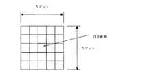
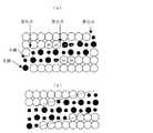
図6は従来例による大中滴各50%からなるハーフトーン処理を施した出力文字の例、図7は従来の大中滴各50%からなるハーフトーン処理を施した斜線部のドット配置を示す図である。Next, examples of dots printed by the ink jet recording apparatus are shown in FIGS.
FIG. 6 shows an example of an output character subjected to halftone processing consisting of 50% each of large and medium drops according to the conventional example, and FIG. 7 shows a dot arrangement in a hatched portion subjected to halftone processing consisting of 50% of each of large and medium drops according to the conventional example. FIG.
図6に示すように斜線部においてジャギーが発生した劣悪な文字品質となってしまう。これは、図7に示すように斜線部ではドットは階段状に配置されるためである。本実施例では、2つの階段状の変化部の間の直線を形成するドットの数が4つの場合(これを傾き1/4の斜線と称する)の例である。 As shown in FIG. 6, the character quality is poor with jaggy occurring in the shaded area. This is because the dots are arranged in a staircase pattern in the shaded area as shown in FIG. This embodiment is an example in which the number of dots forming a straight line between two step-like change portions is four (this is referred to as a diagonal line having a slope of ¼).
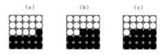
一方、図8は、本発明の実施例による大中滴各50%からなるハーフトーン処理を施した斜線部のドット配置を示したものであり(図7に対応)、(a)〜(d)で、異なるジャギー補正方法を示したものである。図8において、(a)、(b)は変化点の空白部に小滴を付加する例であり、(c)、(d)は空白部に小滴を付加したうえにさらに画像ドットに対しても、小滴に置換した例である。 On the other hand, FIG. 8 shows the dot arrangement of the hatched portion subjected to halftone processing comprising 50% of each large and medium droplet according to the embodiment of the present invention (corresponding to FIG. 7), and (a) to (d). ) Shows different jaggy correction methods. In FIG. 8, (a) and (b) are examples in which a small droplet is added to the blank portion at the change point, and (c) and (d) are further applied to the image dot after adding a small droplet to the blank portion. However, this is an example of substituting with droplets.
さらに詳しく説明すると、(a)は、変化点の空白部(46、51の位置)に小滴を1つ付加した例である。これにより、変化点の空白部46には小滴が印字される。(b)は変化点の空白部(46、45、51、52の位置)に小滴を2個付加した例である。これにより、変化点の空白部2つ45,46,51,52には小滴が印字される。さらに(c)は、(b)に加えて、変化点を形成するドットそのもの(47、50のドット)を小滴に置換した例。これにより、変化点の空白部2つと画像部1つ(45,46,47,50,51,52)には小滴が印字される。(d)は(c)に加えてさらに変化点を形成するドットを2つまで(48,49)小滴に変換した例である。 More specifically, (a) is an example in which one small droplet is added to the blank portion (
これらはすべて、変化点の階段状の段差が、小滴を形成することによって低減され、ドットの構成だけからも、比較的滑らかな斜線部が形成される。さらにインクジェットプリンタでは、インクが紙に着弾後広がるという特性がある。また、普通紙に記録した場合、インクジェットでも染料を主体としたインクを用いた場合にはせっかくドットの構成によりジャギーが改善されても、フェザリングと呼ばれるひげ状のにじみにより、輪郭が凸凹したものとなり改善効果がなくなってしまうのにたいし、本発明に用いたインクによりフェザリング等が低減され、ひげ状のにじみはなくなり、ドットの構成による改善効果が比較的そのまま現れるため、効果的である。 In all of these, the step-like step at the changing point is reduced by forming a droplet, and a relatively smooth hatched portion is formed from the dot configuration alone. Furthermore, an ink jet printer has a characteristic that ink spreads after landing on paper. Also, when recording on plain paper, when ink is used mainly with dyes, even if jaggy is improved by the configuration of dots, the contour is uneven due to whisker-like bleeding called feathering This is effective because the ink used in the present invention reduces feathering and the like, eliminates whisker-like blurring, and the improvement effect of the dot configuration appears relatively as it is. .
また、さらに、本発明のインクでは、フェザリングが低減するが、全体的なにじみは多少なり生じることから、周囲のドットとあいまってドット同士の輪郭部が滑らかになり、ジャギーが目立たなくなる傾向がある。そのため、このインクジェット特有の現象、さらには本発明のインク特有の現象により、ジャギーはほとんど目立たない滑らかな斜線部を形成することが可能となる。なお、本実施例では大中滴各50%の比率のハーフトーン処理での場合に関して述べたが、大中滴を使用したハーフトーン処理において、全て大中滴の比率の場合に関しても同様に実施することができる。 Furthermore, in the ink of the present invention, feathering is reduced, but since overall blurring occurs somewhat, the outline of the dots becomes smoother with the surrounding dots, and jaggies tend not to be noticeable. is there. Therefore, due to the phenomenon peculiar to the ink jet, and also the phenomenon peculiar to the ink of the present invention, it becomes possible to form a smooth hatched portion where jaggies are hardly noticeable. In the present embodiment, the case of halftone processing with a ratio of 50% for each large and medium drop is described. However, in the halftone process using large and medium drops, the same applies to the case of the ratio of all large and medium drops. can do.
また、本実施例では傾き1/4の斜線に関して述べたが、それ以外の傾き(1/3、1/5以下)の斜線、さらにはそれらのミラー反転、90度、180度、270度回転した斜線に対しても同様に実施することができる。 In the present embodiment, the oblique line with the inclination of 1/4 is described, but the oblique line with the other inclination (1/3, 1/5 or less), and the mirror inversion thereof, 90 degrees, 180 degrees, and 270 degrees rotation. The same can be done for the hatched lines.
さらに図19により中小滴各50%からなるハーフトーン処理を施した斜線において2つの階段状変化部の間の直線を形成するドットの数が4の場合(傾き1/4の斜線)の例を示す(a)。
このように変化点の階段状の段差が、小滴を形成することによって低減され、ドットの構成だけからも、比較的滑らかな斜線部が形成される。さらにインクジェットプリンタでは、インクが紙に着弾後広がるという特性がある。Further, in FIG. 19, an example of the case where the number of dots forming a straight line between two step-like change portions in a diagonal line subjected to a halftone process consisting of 50% of each medium droplet is 4 (slant line with an inclination of ¼). Shown (a).
In this way, the stepped step at the changing point is reduced by forming a small droplet, and a relatively smooth hatched portion is formed only from the dot configuration. Furthermore, an ink jet printer has a characteristic that ink spreads after landing on paper.
また、普通紙に記録した場合、インクジェットでも染料を主体としたインクを用いた場合にはせっかくドットの構成によりジャギーが改善されても、フェザリングと呼ばれるひげ状のにじみにより、輪郭が凸凹したものとなり改善効果がなくなってしまうのにたいし、本発明に用いたインクによりフェザリング等が低減され、ひげ状のにじみはなくなり、ドットの構成による改善効果が比較的そのまま現れるため、効果的である。 Also, when recording on plain paper, when ink is used mainly with dyes, even if jaggy is improved by the configuration of dots, the contour is uneven due to whisker-like bleeding called feathering This is effective because the ink used in the present invention reduces feathering and the like, eliminates whisker-like blurring, and the improvement effect of the dot configuration appears relatively as it is. .
また、さらに、本発明のインクでは、フェザリングが低減するが、全体的なにじみは多少なり生じることから、周囲のドットとあいまってドット同士の輪郭部が滑らかになり、ジャギーが目立たなくなる傾向がある。そのため、このインクジェット特有の現象、さらには本発明のインク特有の現象により、ジャギーはほとんど目立たない滑らかな斜線部を形成することが可能となる。 Furthermore, in the ink of the present invention, feathering is reduced, but since overall blurring occurs somewhat, the outline of the dots becomes smoother with the surrounding dots, and jaggies tend not to be noticeable. is there. Therefore, due to the phenomenon peculiar to the ink jet, and also the phenomenon peculiar to the ink of the present invention, it becomes possible to form a smooth hatched portion where jaggies are hardly noticeable.
また、変化点の空白部(46、45、51、52の位置)に小滴を2個付加する方法。さらに、変化点を形成するドットそのもの(47、50のドット)を小滴に置換し、これにより、変化点の空白部2つと画像部1つ(45,46,47,50,51,52)に小滴を印字する方法。さらに変化点を形成するドットを2つまで(48,49)小滴に変換し、これにより、変化点の空白部2つと画像部2つ(45,46,47,50,51,52)に小滴を印字する方法においても同様の効果が得られる。 Also, a method of adding two small droplets to the blank portion (
なお、本実施例では中小滴各50%の比率のハーフトーン処理での場合に関して述べたが、中小滴を使用したハーフトーン処理で
中滴>小滴
となる比率の場合に関しても同様に実施することができる。すなわち、中滴のドット数が小滴のドット数よりも多い場合に関しても同様に実施することができる。
また、本実施例では傾き1/4の斜線に関して述べたが、それ以外の傾きの斜線、さらにはそれらのミラー反転、90度、180度、270度回転した斜線に対しても同様に実施することができる。In the present embodiment, the case of halftone processing with a ratio of 50% for each medium droplet has been described. However, the same operation is performed for the ratio of medium droplet> small droplet with halftone processing using medium droplets. be able to. That is, the same can be applied to the case where the number of dots of medium drops is larger than the number of dots of small drops.
In the present embodiment, the oblique line with the inclination of 1/4 is described, but the same is applied to the oblique line with the inclination other than that, and also to the oblique line with the mirror inverted, rotated 90 degrees, 180 degrees, and 270 degrees. be able to.
さらに、図15により大中滴各50%からなるハーフトーン処理を施した斜線において2つの階段状変化部(F,G)の間の直線を形成するドットの数が2の場合(傾き1/2の斜線)の実施例を示す(a)。
この場合、小滴を変化点の空白に2滴付加すると、斜線を形成する画像ドットと同じ位置(すなわち隣の変化点)まで付加することとなり、階段状の画像を改善することができない(b)。そこで、本発明では、これを解決するために、このような場合には、小滴の付加範囲をその変化点の1画素手前まで(すなわち階段状変化部の間の直線を形成するドットの数―1)としている(c)。これにより傾き1/2の斜線でもジャギーを改善した斜線が得られるようになる。Furthermore, when the number of dots forming a straight line between the two step-like change portions (F, G) in the oblique line subjected to the halftone process consisting of 50% of each of the large and medium droplets according to FIG. (A) shows an example of (2).
In this case, if two droplets are added to the blank at the change point, they are added up to the same position as the image dot forming the diagonal line (that is, the adjacent change point), and the stepped image cannot be improved (b). ). Therefore, in order to solve this problem, in the present invention, in such a case, the addition range of the droplet is set to one pixel before the change point (that is, the number of dots forming a straight line between the step-like change portions). ―1) (c). As a result, an oblique line with improved jaggies can be obtained even with an oblique line having an inclination of 1/2.
なお、本実施例では大中滴各50%の比率のハーフトーン処理での場合に関して述べたが、大中滴を使用したハーフトーン処理において、全て大中滴の比率の場合と、中小滴を使用したハーフトーン処理で
中滴≧小滴
となる比率の場合に関しても同様に実施することができる。すなわち、中滴のドット数が小滴のドット数以上である場合に関しても同様に実施することができる。In the present embodiment, the case of halftone processing with a ratio of 50% for each of large and medium droplets was described. However, in the halftone processing using large and medium droplets, the ratio of all large and medium droplets and medium and small droplets The same can be applied to the case where the ratio of medium droplet ≧ small droplet is obtained in the halftone process used. That is, the same can be applied to the case where the number of dots of medium drops is equal to or greater than the number of dots of small drops.
さらに、図16により大中滴各50%からなるハーフトーン処理を施した斜線において2つの階段状変化部の間の直線を形成するドットの数が1の場合(傾き1/1の斜線)の例を示す(a)。
この場合、小滴を付加すると、斜線を形成する画像ドットと同じ斜線となってしまい、線の幅が太くなってしまう。本発明では、これを解決するために、もともと1/1の斜線は階段状の部分が連続しているため、ジャギーが目立ちにくく、インクジェットプリンタの場合インクの広がりと、多少のにじみによって階段状の部分が緩和される傾向にかるため、このような場合には、小滴を付加しない(言い換えれば階段状変化部の間の直線を形成するドットの数―1=0)ようにしている。これにより傾き1/1の斜線でジャギー付加することによる悪影響をなくすことができる。Further, in FIG. 16, when the number of dots forming a straight line between two step-like change portions is 1 in a diagonal line subjected to halftone processing consisting of 50% of each large and medium droplet (a diagonal line with an inclination of 1/1). An example is shown (a).
In this case, when a small droplet is added, the same oblique line as the image dot forming the oblique line is formed, and the width of the line is increased. In the present invention, in order to solve this problem, since the stepped portion of the 1/1 diagonal line is originally continuous, jaggies are hardly noticeable, and in the case of an ink jet printer, the stepped shape is caused by the spread of ink and some blurring. In such a case, a small droplet is not added (in other words, the number of dots forming a straight line between the staircase-like change portions—1 = 0). As a result, it is possible to eliminate the adverse effect caused by adding jaggies with a slanting line having an inclination of 1/1.
なお、本実施例では大中滴各50%の比率のハーフトーン処理での場合に関して述べたが、大中滴を使用したハーフトーン処理において、全て大中滴の比率の場合と、中小滴を使用したハーフトーン処理で
中滴≧小滴
となる比率の場合に関しても同様に実施することができる。すなわち、中滴のドット数が小滴のドット数以上である場合に関しても同様に実施することができる。In the present embodiment, the case of halftone processing with a ratio of 50% for each of large and medium droplets was described. However, in the halftone processing using large and medium droplets, the ratio of all large and medium droplets and medium and small droplets The same can be applied to the case where the ratio of medium droplet ≧ small droplet is obtained in the halftone process used. That is, the same can be applied to the case where the number of dots of medium drops is equal to or greater than the number of dots of small drops.
さらに、図18により小滴100%からなるハーフトーン処理を施した斜線において2つの階段状変化部の間の直線を形成するドットの数が4の場合(傾き1/4の斜線)の例を示す(a)。
この場合、小滴を付加すると、斜線を形成する画像ドットと同じ斜線となってしまい、階段状の画像を改善することが出来ない。本発明では、これを解決するために、もともと小滴から構成される斜線は濃度が低いため、ジャギーが目立ちにくく、インクジェットプリンタの場合インクの広がりと、多少のにじみによって階段状の部分が緩和される傾向にかるため、このような場合には、小滴を付加しない。同様にこれにより小滴100%からなるハーフトーン処理を施した斜線でジャギー付加することによるホストコンピュータへの無用な負荷をなくすことができる。Furthermore, an example in which the number of dots forming a straight line between two step-like change parts is 4 in a diagonal line subjected to a halftone process consisting of 100% droplets according to FIG. 18 (a diagonal line having an inclination of ¼). Shown (a).
In this case, if a small droplet is added, the same oblique line as the image dot forming the oblique line is formed, and the stepped image cannot be improved. In the present invention, in order to solve this, since the density of the oblique line composed of small droplets is low, jaggies are not noticeable, and in the case of an inkjet printer, the stepped portion is alleviated due to the spread of ink and some blurring. In such a case, no droplet is added. Similarly, this can eliminate unnecessary load on the host computer by adding jaggies with diagonal lines subjected to halftone processing consisting of 100% droplets.
なお、本実施例では小滴100%からなるハーフトーン処理を施した斜線に関して述べたが、ハーフトーン処理における中小滴の比率が
中滴<小滴
となった場合についても同様に実施することができる。すなわち、小滴のドット数が中滴のドット数よりも多い場合に関しても同様に実施することができる。
また、本実施例では傾き1/4の斜線に関して述べたが、それ以外の傾きの斜線、さらにはそれらのミラー反転、90度、180度、270度回転した斜線に対しても同様に実施することができる。In the present embodiment, the oblique lines that have been subjected to the halftone process consisting of 100% of the small droplets have been described, but the same can be applied to the case where the ratio of the medium droplets in the halftone process is medium droplets <small droplets. it can. That is, the same can be applied to the case where the number of dots of the small droplet is larger than the number of dots of the medium droplet.
In the present embodiment, the oblique line with the inclination of 1/4 is described, but the same is applied to the oblique line with the inclination other than that, and also to the oblique line with the mirror inverted, rotated 90 degrees, 180 degrees, and 270 degrees. be able to.
以上のように、傾きとハーフトーンの階調によってジャギー補正方法を変えることで、それぞれの傾きに最適な補正が可能となる。 As described above, it is possible to perform optimum correction for each inclination by changing the jaggy correction method depending on the inclination and the gradation of the halftone.
ここで、変化点に小滴を形成する方法について述べる。
小滴を付加あるいは置換する方法としては、パターンマッチングが優れた方法として用いられ。図20は、パターンマッチングに用いられるウインドウの例である。ウインドウサイズとしては、横m、縦n(m×n)のサイズである。以下の説明は、m=5、n=5の場合(図11)で説明する。Here, a method of forming a droplet at the changing point will be described.
As a method for adding or replacing droplets, pattern matching is used as an excellent method. FIG. 20 is an example of a window used for pattern matching. The window size is a size of horizontal m and vertical n (m × n). The following description will be made in the case of m = 5 and n = 5 (FIG. 11).
ハーフトーン処理を施していないフォントデータは、プリンタードライバーソフトで、ビットマップデータに展開される。ビットマップデータはフォントを形成するドットを示したものである。フォントデータとしてのビットマップデータに対して、各ビットを前述のウインドウ単位でパターンマッチングを実施する。 Font data that has not been subjected to halftone processing is expanded into bitmap data by printer driver software. Bitmap data indicates the dots forming the font. For bit map data as font data, each bit is subjected to pattern matching in the aforementioned window unit.
図12にその処理のフローチャートを示す。まず、フォントデータの先頭に注目画素をセットする。
注目画素を中心に、ウインドウに相当するフォントデータのビットマップデータを取得する。したがって、取得したビットマップデータは5×5の25ドット分のデータである。パターンマッチングにより、取得したデータと、あらかじめ設定していた小滴を付加あるいは置換するパターン(以下参照パターンという)のデータとを比較し、マッチした場合に、注目画素を小滴を示すデータに置換する。これらの処理は、1画素を1バイトのデータとして扱ってもよいし、1ビットのデータとして扱っても良い。FIG. 12 shows a flowchart of the process. First, the target pixel is set at the head of the font data.
Bitmap data of font data corresponding to the window is acquired with the pixel of interest at the center. Accordingly, the acquired bitmap data is 5 × 5 data for 25 dots. By pattern matching, the acquired data is compared with the data of a pattern that adds or replaces a preset droplet (hereinafter referred to as the reference pattern). If there is a match, the pixel of interest is replaced with data indicating the droplet. To do. In these processes, one pixel may be handled as 1-byte data or 1-bit data.
1バイトのデータとして扱う場合は、25ドット分のデータを表すには25バイト必要であるのに対して、1ビットのデータとして扱う場合は、25ドット分のデータを表すには4バイトのデータ量(注目画素以外のデータのみに対して行う場合は3バイトでよい)で済むので、1ビットのデータとして扱ったほうが、処理するデータ数が小さく、メモリーの節約、処理速度の向上が図れるため、好ましい。 When handled as 1 byte data, 25 bytes are required to represent 25 dots of data, whereas when handled as 1 bit data, 4 bytes of data are used to represent 25 dots of data. Since the amount (only 3 bytes is sufficient if it is performed only on data other than the pixel of interest), the number of data to be processed is smaller, memory can be saved, and the processing speed can be improved by treating it as 1-bit data. ,preferable.
パターンマッチングの例を図14によりさらに詳細に説明する。
図14(a)は参照パターン、(b)はフォントデータの46を注目画素としたときのウインドウの状態である。両者のドットのパターンは一致するため、注目画素46の位置が、空白から小滴に置換される(c)。
小滴データの生成において、小滴を示すデータは、元のフォントデータがビットマップデータのように0(空白)と255(印字データ)で表されるとき、あるいは0(空白)、1(印字データ)のように2値で表されるときに、いったん0(空白)、255(印字データ)のように変換したときには、空白データ、フォントを形成するデータそのものを小滴を表すデータ(例えばそれぞれ85)に置換してもよい。また、0と1のまま処理するときには、フォントデータと同じサイズの別のメモリ(小滴データ用メモリ)設け、その中の小滴をつける位置に印字データを表す1を生成すればよい。パターンマッチングにより生成した小滴、大滴を示すデータで構成されたフォントデータ(前者の場合)、あるいは小滴用2値(0、1)データと元の2値(0、1)フォントデータとで(後者の場合)、小滴、大滴を印字することにより、図8のようなジャギーが改善された斜線を実現することができる。An example of pattern matching will be described in more detail with reference to FIG.
FIG. 14A shows the reference pattern, and FIG. 14B shows the window state when the
In the generation of droplet data, the data indicating a droplet is generated when the original font data is represented by 0 (blank) and 255 (print data) like bitmap data, or 0 (blank), 1 (print When data is expressed in binary as in (Data), and once converted into 0 (blank) and 255 (print data), the blank data and the data forming the font itself are data representing droplets (for example, 85). When processing with 0 and 1 as it is, another memory (small droplet data memory) having the same size as the font data may be provided, and 1 representing the print data may be generated at the position where the small droplet is to be placed. Font data composed of data indicating small droplets and large droplets generated by pattern matching (in the former case), or binary (0, 1) data for small droplets and original binary (0, 1) font data In the latter case, by printing small droplets and large droplets, it is possible to realize diagonal lines with improved jaggy as shown in FIG.
5×5のウインドウ及び参照パターンを用いることにより、変化点を中心に前後2ドットの空白及び画像ドットに対して小滴に置換するかどうかの判断が可能となる。例えば、図17(a)の参照パターンにより、45の位置が小滴に置換することができる。同様に図17(b)により47が、(c)により48のドットが小滴に置換される。 By using the 5 × 5 window and the reference pattern, it is possible to determine whether or not to replace the front and rear two-dot blanks and image dots with small droplets around the change point. For example, the position of 45 can be replaced with a droplet by the reference pattern of FIG. Similarly, 47 dots are replaced with droplets according to FIG. 17B and 48 dots are replaced with droplets according to FIG.
変化点の前後2ドット分に対して実施可能な理由は、例えば図14ウインドウの位置で注目画素を判断するには変化点がウインドウの外になるため、変化点を検出できないためである。これを解消して、適切な小滴を付加する場合には、ウインドウ及び参照パターンを7×7のサイズにすることにより可能となる。
すなわち、ウインドウのサイズ、参照パターンのサイズを大きくすることにより、水平あるいは垂直に近い斜線の変化点を検出でき、その傾きに応じた小滴を付加することが可能となり、それらの斜線品質をよりいっそう最適にすることができる。The reason why it can be applied to two dots before and after the change point is that, for example, in order to determine the pixel of interest at the position of the window in FIG. To solve this problem and add appropriate droplets, it is possible to make the window and
That is, by increasing the size of the window and the size of the reference pattern, it is possible to detect the change point of the diagonal line near horizontal or vertical, and it is possible to add small droplets according to the inclination, and to improve the quality of the diagonal line. It can be made even more optimal.
つまり、ウインドウ及び参照パターンのサイズは本実施例で使用したものに限らず、小滴への置換をどこまで実施する必要があるか、処理時間が印字速度に対して間に合うかによって決まる。さらに言うと、このサイズが大きくなるとパターンマッチングするデータが大きくなるため、パターンマッチングに時間を要する。そのため、処理時間からは、そのサイズとしてはできるだけ小さいほうがよい。
一方、変化点の前後いくつのドットを小滴をすれば良いかは、ジャギー補正による文字品質から決まるので、処理速度と、文字品質から最適なサイズを決定する必要がある。本発明者の実験により、前述のようなインクを用いた場合、インクの広がりによる隣接ドットとの凹凸の低減から、7ドット以下の小滴付加でも、十分文字品質の向上が図れることがわかり、また、処理速度も、10PPM以上のスループットを達成することができることがわかった。したがって、ウインドウのサイズとしては、m≦7あるいはn≦7のサイズが適している。That is, the sizes of the window and the reference pattern are not limited to those used in the present embodiment, but are determined depending on how much replacement with the droplets needs to be performed and whether the processing time is in time for the printing speed. Furthermore, since the data for pattern matching increases as this size increases, time is required for pattern matching. Therefore, from the processing time, the size should be as small as possible.
On the other hand, how many dots before and after the change point should be dropped is determined by the character quality by jaggy correction, so it is necessary to determine an optimum size from the processing speed and the character quality. According to the experiments of the present inventors, when the ink as described above is used, it is understood that the character quality can be sufficiently improved even by adding a small droplet of 7 dots or less, because the unevenness with the adjacent dots due to the spread of the ink is reduced. It was also found that the processing speed can achieve a throughput of 10 PPM or more. Accordingly, a size of m ≦ 7 or n ≦ 7 is suitable as the size of the window.
また、同じサイズのウインドウを用いた場合に、処理速度の点から実施例(8図(a)〜(e))を比較すると、8図(a)が最も速く、(b)、(c)、(d)、(e)の順に遅くなる。
これは、1つには、処理方法が、(a)、(b)が注目画素が空白の場合のみに、(c)が画像ドットの場合のみにパターンマッチングを実行すればよいのに比べ、(d)、(e)の場合には、空白の場合と、画像ドットの場合の両方(すなわちすべてのフォントデータでパターンマッチングを行う必要があるためである。言い換えれば、空白にのみ小滴を付加することにより、高速にジャギーを改善したフォントデータを作成することができる。また、画像ドットのみを小滴に置換することにより、高速にジャギーを改善したフォントデータを作成することができる。In addition, when using windows of the same size, when comparing the embodiments (FIGS. 8A to 8E) in terms of processing speed, FIG. 8A is the fastest, and FIGS. , (D), (e) in order.
For one thing, as compared with the case where the processing method has only to execute pattern matching only when the target pixel is blank in (a) and (b) and only when (c) is an image dot, In the cases (d) and (e), it is necessary to perform pattern matching in both the case of a blank and the case of an image dot (that is, all font data needs to be subjected to pattern matching. By adding, it is possible to create font data with improved jaggy at high speed, and it is possible to create font data with improved jaggy at high speed by replacing only image dots with small droplets.
2つ目としては、必要な参照パターンの数が、(a)、((b)=(c))、(d)、(e)の順に多くなるためである。これは、(b)を実施するには、(a)の参照パターンにさらに空白2ドット目を判断する参照パターンが必要であり、(d)では、さらにドット1つ目を判断する参照パターンが必要であり、(e)では、さらにドット2つ目を判断するための参照パターンが必要となるためである。 Second, the number of necessary reference patterns increases in the order of (a), ((b) = (c)), (d), (e). In order to implement (b), a reference pattern for determining the second blank dot is required in the reference pattern of (a), and in (d), a reference pattern for determining the first dot is further included. This is because (e) requires a reference pattern for determining the second dot.
ここで、図21により空白部のみに小滴の付加処理を行う方法を、図22により画像を形成するドットのみに小滴付加処理を行う方法について述べる。
空白部のみに小滴を付加する方法をのべる。図21にそのフローチャートを示す。Here, a method for performing droplet addition processing only on a blank portion with reference to FIG. 21 and a method for performing droplet addition processing only on dots forming an image will be described with reference to FIG.
Describe how to add droplets only to blank areas. FIG. 21 shows the flowchart.
まず、フォントデータの先頭に注目画素をセットする。
注目画素に対する画像データをみて、そのデータが空白のデータかフォントを形成するデータ(=印字するデータ)かを判断する。その結果、空白を示すデータの時のみ以下のパターンマッチングを実施し、フォントを形成するデータの場合にはパターンマッチングによる変化点の検出を行わない。これにより、フォントを形成するデータでパターンマッチングをする時間がなくなるので、処理速度の向上が図れる。
空白を示すデータのとき、注目画素を中心に、ウインドウに相当するフォントデータのビットマップデータを取得する。したがって、取得したビットマップデータは5×5の25ドット分のデータである。パターンマッチングにより、取得したデータと、あらかじめ設定していた小滴を付加あるいは置換するパターン(以下参照パターンという)のデータとを比較し、マッチした場合に、注目画素を小滴を示すデータに置換する。First, the target pixel is set at the head of the font data.
By looking at the image data for the target pixel, it is determined whether the data is blank data or data forming a font (= data to be printed). As a result, the following pattern matching is executed only for data indicating a blank, and change points are not detected by pattern matching in the case of data forming a font. This eliminates the time for pattern matching with the data forming the font, thereby improving the processing speed.
In the case of data indicating a blank, bitmap data of font data corresponding to the window is acquired with the pixel of interest at the center. Therefore, the acquired bitmap data is 5 × 5 data for 25 dots. By pattern matching, the acquired data is compared with the data of a pattern that adds or replaces a preset droplet (hereinafter referred to as a reference pattern). If there is a match, the pixel of interest is replaced with data indicating the droplet. To do.
これらの処理は、1画素を1バイトのデータとして扱ってもよいし、1ビットのデータとして扱っても良い。1バイトのデータとして扱う場合は、25ドット分のデータを表すには25バイト必要であるのに対して、1ビットのデータとして扱う場合は、25ドット分のデータを表すには4バイトのデータ量(注目画素以外のデータのみに対して行う場合は3バイトでよい)で済むので、1ビットのデータとして扱ったほうが、処理するデータ数が小さく、メモリーの節約、処理速度の向上が図れるため、好ましい。 In these processes, one pixel may be handled as 1-byte data or 1-bit data. When handled as 1 byte data, 25 bytes are required to represent 25 dots of data, whereas when handled as 1 bit data, 4 bytes of data are used to represent 25 dots of data. Since the amount (only 3 bytes is sufficient if it is performed only on data other than the pixel of interest), the number of data to be processed is smaller, memory can be saved, and the processing speed can be improved by treating it as 1-bit data. ,preferable.
パターンマッチングの例を図14によりさらに詳細に説明する。図14(a)は参照パターン、(b)はフォントデータの46を注目画素としたときのウインドウの状態である。両者のドットのパターンは一致するため、注目画素46の位置が、空白から小滴に置換される(c)。
5×5のウインドウ及び参照パターンを用いることにより、変化点に隣接する空白2の画像ドットに対して小滴を付加するかどうかの判断が可能となる。An example of pattern matching will be described in more detail with reference to FIG. FIG. 14A shows the reference pattern, and FIG. 14B shows the window state when the
By using the 5 × 5 window and the reference pattern, it is possible to determine whether or not to add a droplet to the blank 2 image dot adjacent to the change point.
次に、フォントを形成するデータ(=印字データ)のみを小滴に置換する方法をのべる。図22にそのフローチャートを示す。
まず、フォントデータの先頭に注目画素をセットする。
注目画素に対する画像データをみて、そのデータが空白のデータかフォントを形成するデータ(=印字するデータ)かを判断する。その結果、フォントを形成するデータの時のみ以下のパターンマッチングを実施し、空白を形成するデータの場合にはパターンマッチングによる変化点の検出を行わない。これにより、空白を形成するデータでパターンマッチングをする時間がなくなるので、処理速度の向上が図れる。Next, a method of replacing only the data (= print data) forming the font with a droplet will be described. The flowchart is shown in FIG.
First, the target pixel is set at the head of the font data.
By looking at the image data for the target pixel, it is determined whether the data is blank data or data forming a font (= data to be printed). As a result, the following pattern matching is performed only for data forming a font, and change points are not detected by pattern matching for data forming a blank. This eliminates the time for pattern matching with the data forming the blank, thereby improving the processing speed.
空白を示すデータのとき、注目画素を中心に、ウインドウに相当するフォントデータのビットマップデータを取得する。したがって、取得したビットマップデータは5×5の25ドット分のデータである。
パターンマッチングにより、取得したデータと、あらかじめ設定していた小滴を付加あるいは置換するパターン(以下参照パターンという)のデータとを比較し、マッチした場合に、注目画素を小滴を示すデータに置換する。In the case of data indicating a blank, bitmap data of font data corresponding to the window is acquired with the pixel of interest at the center. Therefore, the acquired bitmap data is 5 × 5 data for 25 dots.
By pattern matching, the acquired data is compared with the data of a pattern that adds or replaces a preset droplet (hereinafter referred to as a reference pattern). If there is a match, the pixel of interest is replaced with data indicating the droplet. To do.
これらの処理は、1画素を1バイトのデータとして扱ってもよいし、1ビットのデータとして扱っても良い。1バイトのデータとして扱う場合は、25ドット分のデータを表すには25バイト必要であるのに対して、1ビットのデータとして扱う場合は、25ドット分のデータを表すには4バイトのデータ量(注目画素以外のデータのみに対して行う場合は3バイトでよい)で済むので、1ビットのデータとして扱ったほうが、処理するデータ数が小さく、メモリーの節約、処理速度の向上が図れるため、好ましい。 In these processes, one pixel may be handled as 1-byte data or 1-bit data. When handled as 1 byte data, 25 bytes are required to represent 25 dots of data, whereas when handled as 1 bit data, 4 bytes of data are used to represent 25 dots of data. Since the amount (only 3 bytes is sufficient if it is performed only on data other than the pixel of interest), the number of data to be processed is smaller, memory can be saved, and the processing speed can be improved by treating it as 1-bit data. ,preferable.
パターンマッチングの例を図14によりさらに詳細に説明する。図14(d)は参照パターン、(e)はフォントデータの47を注目画素としたときのウインドウの状態である。両者のドットのパターンは一致するため、注目画素47の位置が、大滴を示す印字データから小滴を示すデータに置換される(f)。
5×5のウインドウ及び参照パターンを用いることにより、変化点に隣接する2つのフォントデータを示すドットに対して小滴に置換するかどうかの判断が可能となる。An example of pattern matching will be described in more detail with reference to FIG. FIG. 14D shows the reference pattern, and FIG. 14E shows the window state when the
By using the 5 × 5 window and the reference pattern, it is possible to determine whether or not to replace a dot indicating two font data adjacent to the change point with a droplet.
図23、図24により別の実施例を示す。
フォントデータとしてのビットマップデータに対して、各ビットを前述のウインドウ単位でパターンマッチングを実施する。
図23にそのフローチャートを示す。まず、フォントデータの先頭に注目画素をセットする。FIG. 23 and FIG. 24 show another embodiment.
For bit map data as font data, each bit is subjected to pattern matching in the aforementioned window unit.
FIG. 23 shows the flowchart. First, the target pixel is set at the head of the font data.
注目画素を中心に、ウインドウに相当するフォントデータのビットマップデータを取得する。したがって、取得したビットマップデータは5×5の25ドット分のデータである。パターンマッチングにより、取得したデータと、あらかじめ設定していた小滴及び中滴を付加あるいは置換するパターン(以下参照パターンという)のデータとを比較し、マッチした場合に、注目画素を小滴及び中滴を示すデータに置換する。 Bitmap data of font data corresponding to the window is acquired with the pixel of interest at the center. Therefore, the acquired bitmap data is 5 × 5 data for 25 dots. By pattern matching, the acquired data is compared with the preset data for adding or replacing small and medium droplets (hereinafter referred to as “reference pattern”). Replace with data indicating drops.
これらの処理は、1画素を1バイトのデータとして扱ってもよいし、1ビットのデータとして扱っても良い。1バイトのデータとして扱う場合は、25ドット分のデータを表すには25バイト必要であるのに対して、1ビットのデータとして扱う場合は、25ドット分のデータを表すには4バイトのデータ量(注目画素以外のデータのみに対して行う場合は3バイトでよい)で済むので、1ビットのデータとして扱ったほうが、処理するデータ数が小さく、メモリの節約、処理速度の向上が図れるため、好ましい。 In these processes, one pixel may be handled as 1-byte data or 1-bit data. When handled as 1 byte data, 25 bytes are required to represent 25 dots of data, whereas when handled as 1 bit data, 4 bytes of data are used to represent 25 dots of data. Since the amount (only 3 bytes is sufficient if it is performed only for data other than the pixel of interest) is handled as 1-bit data, the number of data to be processed is smaller, saving memory and improving processing speed. ,preferable.
このとき、小滴、中滴を示すデータは、元のフォントデータがビットマップデータのように0(空白)と255(印字データ)で表されるとき、あるいは0(空白)、1(印字データ)のように2値で表されるときに、いったん0(空白)、255(印字データ)のように変換したときには、空白データ、フォントを形成するデータそのもの小滴、中滴を表すデータ(例えばそれぞれ85,170)に置換してもよい。 At this time, the data indicating small droplets and medium droplets are displayed when the original font data is represented by 0 (blank) and 255 (print data) as in bitmap data, or 0 (blank) and 1 (print data). ), And once converted to 0 (blank) and 255 (print data), the data forming the font itself is data representing small droplets and medium droplets (for example, They may be replaced with 85 and 170, respectively.
また、0と1のまま処理するときには、フォントデータと同じサイズの別のメモリを複数(本実施例の場合、小滴と中滴の2種類であるので小滴用、中滴用の2つ)設け、それぞれの中の小滴、中滴をつける位置に印字データを表す1を生成すればよい。パターンマッチングにより生成した小滴、中滴、大滴を示すデータで構成されたフォントデータ(前者の場合)、あるいは小滴用2値(0、1)データ、中滴用の2値(0、1)データと元のフォントデータ(2値)とで、小滴、中滴、大滴を印字することにより、図24のようなジャギーが改善された斜線を実現することができる。 Further, when processing with 0 and 1 as it is, a plurality of different memories having the same size as the font data (in the case of this embodiment, there are two types of small and medium droplets, two for small droplets and one for medium droplets). 1) representing the print data may be generated at the positions where the small droplets and the medium droplets are placed. Font data composed of data indicating small droplets, medium droplets, and large droplets generated by pattern matching (in the former case), binary data for small droplets (0, 1), binary data for medium droplets (0, 1) By printing small droplets, medium droplets, and large droplets with the data and the original font data (binary), diagonal lines with improved jaggy as shown in FIG. 24 can be realized.
なお、図24では大滴100%の階調での実施例を示したが、大中滴を使用したハーフトーン処理において、全て大中滴の比率の場合と、中小滴を使用したハーフトーン処理で
中滴≧小滴
となる比率の場合に関しても同様に実施することができる。すなわち、中滴のドット数が小滴のドット数以上である場合に関しても同様に実施することができる。FIG. 24 shows an example with a gradation of 100% large droplets. However, in the halftone processing using large and medium droplets, the ratio of all large and medium drops and the halftone processing using medium and small droplets are used. In the case of the ratio of medium droplet ≧ small droplet, the same operation can be performed. That is, the same can be applied to the case where the number of dots of medium drops is equal to or greater than the number of dots of small drops.
次に、傾きによって補正方法を変更する方法について述べる。
本発明はフォントデータとのパターンマッチングによって注目画素を小滴、あるいは中滴に変更するか、または何もしないかが選択される。したがって、参照するパターンとしては小さな傾きから、大きな傾きにまで用意されている。そこで、1/1より大きな場合のパターンと、1/1以下の場合のパターンとで、注目画素を何に変更するかという情報を変えればよい。Next, a method for changing the correction method depending on the inclination will be described.
In the present invention, it is selected whether the pixel of interest is changed to a small droplet, a medium droplet, or nothing by pattern matching with font data. Therefore, the patterns to be referred to are prepared from a small inclination to a large inclination. Therefore, what is necessary is just to change the information about what the target pixel is changed between a pattern larger than 1/1 and a pattern smaller than 1/1.
この方法について、図27を参照してさらに詳しく述べる。
図27は、傾き4/1(図27(a))と1/4(図27(b))の参照パターンの一例である。フォントデータをパターンマッチングするとき、参照パターンを小滴変換用の参照パタンと、中滴用の参照パターン、さらには何もしない参照パターンに分けておき、それぞれでパターンマッチングすることによって、マッチした場合に注目画素をどのサイズのドットに変換するか、すなわちどのドットデータに変換するかがわかる。図27の例では、(a)のパターンは中滴、(b)のパターンは小滴の変換パターンとすることで、傾き4/1のときには中滴、傾き1/4の時には小滴に変換される。This method will be described in more detail with reference to FIG.
FIG. 27 is an example of reference patterns having inclinations of 4/1 (FIG. 27A) and 1/4 (FIG. 27B). When pattern matching is performed on font data, the reference pattern is divided into a reference pattern for small droplet conversion, a reference pattern for medium droplets, and a reference pattern that does nothing. It can be seen to which size dot the target pixel is converted, that is, to which dot data. In the example of FIG. 27, the pattern of (a) is a medium drop and the pattern of (b) is a small drop conversion pattern, which is converted to a medium drop when the inclination is 4/1 and to a small drop when the inclination is 1/4. Is done.
これらのフォントデータの作成は、前述したようにインクジェット記録装置に画像データを送るためのPC上にプリンタードライバーソフトとよばれるソフトウェアとして搭載される。そのため、CDROMやネットワーク上のホストコンピュータのハードディスクに、ジャギー補正手段を記述したソフトとして保存され、それをインストールすることによって、各PCで動作可能となる。 These font data are created as software called printer driver software on a PC for sending image data to the ink jet recording apparatus as described above. Therefore, software stored in the CDROM or the hard disk of the host computer on the network is stored as software describing the jaggy correction means, and can be operated on each PC by installing it.
また、別の形態として、インクジェット記録装置そのものに検出手段を搭載する方法もある。この方法としては、例えば、図28に示すようにCPUとそれを動かすためのプログラムが格納されたROMとで構成されたファームウエアの場合、ROMに格納されたプログラムにジャギー補正の処理方法、パターンマッチングを行うための参照パターンを入れることによって、CPUを用いて、入ってきた文字コードからビットマップデータを作成するときにジャギー補正を行うようにすればよい。この場合、輪郭部の階段状変化部の検出はCPUで行われるため、CPUが検出手段となる。また、別の方法としては、CPUを用いないで、ハードウエアのみで実現することも可能である。このようにすることで、PCとインクジェットプリンター間のデータ転送がビットマップをデータを用いないで良いので高速になり、スループット向上が図れる。 As another form, there is a method in which the detection means is mounted on the ink jet recording apparatus itself. As this method, for example, in the case of firmware comprising a CPU and a ROM storing a program for operating it as shown in FIG. 28, a jaggy correction processing method and pattern are added to the program stored in the ROM. By introducing a reference pattern for matching, jaggy correction may be performed when creating bitmap data from the entered character code using the CPU. In this case, since the CPU detects the stepped change portion of the contour portion, the CPU serves as the detection means. Further, as another method, it is possible to realize only by hardware without using a CPU. By doing so, the data transfer between the PC and the ink jet printer can be performed at a high speed because the bitmap data need not be used, and the throughput can be improved.
次に、このようにして作成したフォントデータをインクジェット記録装置で記録紙上に印字する方法について述べる。
図9はヘッドの駆動波形を説明する図である。図10はヘッドの駆動回路(図4のヘッド駆動部24に対応)の例である。図13はドライバーICの例である。Next, a method for printing the font data created in this way on recording paper with an ink jet recording apparatus will be described.
FIG. 9 is a diagram for explaining a driving waveform of the head. FIG. 10 shows an example of a head drive circuit (corresponding to the head drive unit 24 of FIG. 4). FIG. 13 shows an example of a driver IC.
印字データとしてのフォントデータは、図4のデータ処理部27ならびに印字制御部23において、ヘッドのならびに対応した立て横変換と、ヘッドを大滴、小滴、非印字の3値を打ち分けるために必要な2ビットの駆動データの生成とが行われ、駆動データS2としてヘッドの駆動周期に応じてヘッド駆動回路に送られる。したがって駆動データとしては、チャンネル数の2倍のビット数となる。ヘッド駆動回路に送られる信号としては、その他に駆動データをドライバーIC内のシフトレジスタ60でシフトさせるためのクロック信号S3とシフトレジスタないのデータがチャンネル数そろった時点でラッチ回路61に保持するためのラッチ信号S1と、駆動波形を画像ドットを形成するサイズのドット(大滴)に対応した駆動波形、小滴に対応した駆動波形を選択するための駆動波形選択信号(M1〜M3)が送られる。 The font data as the print data is used in the
一方、駆動波形を生成する駆動波形生成部としては、CPUから駆動波形の形成する駆動波形データ(デジタル信号)をD/Aコンバータによりアナログ信号に変換し、これを実際の駆動電圧まで増幅する増幅機、さらにヘッドの駆動による電流を十分供給するための電流増幅機を経て、図9のような駆動波形がドライバーICのVpに入力される。ドライバーICでは、駆動データに応じて、データセレクター62により、駆動波形選択信号(M1〜M3、ロジック信号)の1つが選択され、ロジック信号を駆動電圧レベルに変換するレベルシフター63を介して、スイッチング手段であるトランスミッションゲート64のゲートに入力される。 On the other hand, as a drive waveform generation unit for generating a drive waveform, drive waveform data (digital signal) formed by the drive waveform from the CPU is converted into an analog signal by a D / A converter, and this is amplified to amplify the actual drive voltage. Then, a drive waveform as shown in FIG. 9 is input to Vp of the driver IC through a current amplifier for supplying a sufficient current by driving the head. In the driver IC, one of the drive waveform selection signals (M1 to M3, logic signal) is selected by the data selector 62 in accordance with the drive data, and switching is performed via the level shifter 63 that converts the logic signal to the drive voltage level. It is inputted to the gate of the transmission gate 64 as means.
したがってトランスミッションゲートは、選択された駆動波形選択信号の長さに応じて、スイッチングされ、図9に示すような小滴用の波形(a)、大滴用の波形(c)が出力端子(本実施例のドライバーICでは13−1〜192)に出力されることになる。また、本実施例では、さらに中滴用の駆動波形(b)も選択できるようになっている。これらの波形に応じて、PZTは駆動し、小滴、大滴を打ち分けることができる。本実施例では、1つの駆動波形から小滴用、大滴用波形を生成しているので、駆動波形を供給する回路、信号線が1つでよく、コスト低減、回路基板、伝送線の小型化が図れる。 Therefore, the transmission gate is switched according to the length of the selected drive waveform selection signal, and the waveform (a) for small droplets and the waveform (c) for large droplets as shown in FIG. In the driver IC of the embodiment, it is output to 13-1 to 192). In this embodiment, the drive waveform (b) for medium droplets can also be selected. In response to these waveforms, the PZT can be driven to divide small droplets and large droplets. In the present embodiment, since the waveform for small droplets and the waveform for large droplets are generated from one drive waveform, only one circuit and signal line are required to supply the drive waveform, cost reduction, circuit board, and compact transmission line. Can be achieved.
このようにして、小滴を付加したフォントデータを実際に以下の条件で、インクジェットヘッドで普通紙に印字してその文字品質を評価した。
・ ヘッド:384ノズル/色
ノズルピッチ=84μm(300dpi相当)
・ 画像解像度:300dpi
・ ドットサイズ:大滴120μm、小滴40μm
・ 文字:MS明朝 フォントサイズ=6、10、12、20、30、50、80ポイント
・ ハーフトーン処理:大中滴各50%、中小滴各50%
・ ジャギー補正方法:斜線部傾きにより変更(表1参照)
・ 印字方法:パス数(1ライン形成するスキャン数)=1、インターレス=なし
・ 紙:リコー マイペーパTAIn this way, font data with small droplets was actually printed on plain paper with an inkjet head under the following conditions, and the character quality was evaluated.
Head: 384 nozzles / color
Nozzle pitch = 84 μm (equivalent to 300 dpi)
・ Image resolution: 300 dpi
・ Dot size: Large droplet 120μm, Small droplet 40μm
・ Character: MS Mincho Font size = 6, 10, 12, 20, 30, 50, 80 points ・ Halftone processing: 50% for large and medium drops, 50% for small and medium drops
・ Jaggy correction method: Changed according to the sloped area (see Table 1)
-Printing method: Number of passes (number of scans for forming one line) = 1, Interlace = None-Paper: Ricoh My Paper TA

上記ジャギー補正を実施した文字と、比較のために、(比較例1)補正をまったく行わなかった文字、すなわち大滴のみで印字した文字と、(比較例2)傾きに係らず全て図8(e)の補正を行った文字で文字品質を比較した。その結果、本発明によるジャギー補正が最も文字品質が良く、ついで比較例2、最も悪いのが比較例1であった。また、本発明の実施例ではフェザリングもなく、画像濃度も十分な文字が得られた。 For comparison, the character with the jaggy correction is compared with (Comparative Example 1) the character without any correction, that is, the character printed with only a large drop, and (Comparative Example 2). Character quality was compared with the corrected characters of e). As a result, the jaggy correction according to the present invention had the best character quality, followed by Comparative Example 2 and the worst was Comparative Example 1. Further, in the example of the present invention, there was no feathering and characters with sufficient image density were obtained.
本実施例においては、普通紙に印字したときの例を示したが、コート紙や、光沢紙、OHPフィルムなどに印字するときにも本発明を適用することにより、同様の効果を得ることができる。また、これらの紙種によって、ジャギー補正処理を実施する場合と、しない場合とを選択してもよい。 In this embodiment, an example of printing on plain paper is shown, but the same effect can be obtained by applying the present invention to printing on coated paper, glossy paper, OHP film, and the like. it can. Moreover, you may select the case where jaggy correction processing is implemented and the case where it does not carry out according to these paper types.
また、本実施例では、300dpiで文字を印字した例を示したが、より低解像度の200dpi、150dpiの文字に対しても、文字を構成するドット径が大きくなり、階段状の段差がさらに目立つことから、本実施例が好適に適用でき、その効果も大きい。しかし、解像度が600dpi、1200dpi、2400dpiといった高密度の場合には、フォントを構成するドット数が多く、ドットサイズも小さいためジャギーが目立たない。そのため、異なる解像度で印字する複数の印字モードを有するインクジェットプリンタの場合、その解像度によって、本発明を実施するモードと、実施しないモードを設け、解像度に応じて選択するのがスループットの向上をいう点では好ましい。
その解像度の目安としては、一般的には450dpi以上であれば、ジャギーが目立たない文字品質が得られることから、360dpi以下の場合は適用し、450dpi以上では適用しないとするのがよい。すなわち360dpi以下の場合にのみ、変化点の検出を実施することで、処理時間を短縮することができる。In the present embodiment, an example is shown in which characters are printed at 300 dpi. However, even with lower resolution 200 dpi and 150 dpi characters, the dot diameter constituting the characters is increased, and the stepped steps are more conspicuous. Therefore, the present embodiment can be suitably applied and the effect is great. However, when the resolution is as high as 600 dpi, 1200 dpi, and 2400 dpi, jaggy is not conspicuous because the number of dots constituting the font is large and the dot size is small. For this reason, in the case of an inkjet printer having a plurality of print modes for printing at different resolutions, a mode for implementing the present invention and a mode for not performing the present invention are provided depending on the resolution, and selecting according to the resolution means an improvement in throughput. Then, it is preferable.
As a measure of the resolution, generally, when 450 dpi or more is obtained, a character quality with inconspicuous jaggies can be obtained. Therefore, it is preferable that 360 dpi or less is applied, and 450 dpi or more is not applied. That is, the processing time can be shortened by detecting the change point only in the case of 360 dpi or less.
さらに別の実施例を示す。
・ ヘッド:384ノズル/色
ノズルピッチ=84μm(300dpi相当)
・ 画像解像度:300dpi
・ ドットサイズ:大滴120μm、中滴、70μm、小滴40μm
・ 文字:MS明朝 フォントサイズ=6、10、12、20、30、50、80ポイント
・ ハーフトーン処理:大中滴各50%、中小滴各50%
・ ジャギー補正方法:斜線部傾きにより変更(表2参照)
・ 印字方法:パス数(1ライン形成するスキャン数)=1、インターレス=なし
・ 紙:リコー マイペーパTAYet another embodiment is shown.
Head: 384 nozzles / color
Nozzle pitch = 84 μm (equivalent to 300 dpi)
・ Image resolution: 300 dpi
・ Dot size: Large droplet 120μm, Medium droplet, 70μm, Small droplet 40μm
・ Character: MS Mincho Font size = 6, 10, 12, 20, 30, 50, 80 points ・ Halftone processing: 50% for large and medium drops, 50% for small and medium drops
・ Jagged correction method: Changed by the sloped area (see Table 2)
-Printing method: Number of passes (number of scans for forming one line) = 1, Interlace = None-Paper: Ricoh My Paper TA
上記ジャギー補正を実施した文字と、比較のために、〔比較例1〕補正をまったく行わなかった文字、すなわち大滴のみで印字した文字と、〔比較例2〕傾きに係らず全て図8(e)の補正を行った文字とで文字品質を比較した。
その結果、本発明によるジャギー補正が最も文字品質が良く、ついで比較例2、最も悪いのが比較例1であった。また、本発明の実施例ではフェザリングもなく、画像濃度も十分な文字が得られた。For comparison, [Comparative Example 1] characters that were not corrected at all, that is, characters printed only with large droplets, and [Comparative Example 2] regardless of the inclination, are all shown in FIG. The character quality was compared with the characters subjected to the correction of e).
As a result, the jaggy correction according to the present invention had the best character quality, followed by Comparative Example 2 and the worst was Comparative Example 1. Further, in the example of the present invention, there was no feathering and characters with sufficient image density were obtained.
本実施例においては、普通紙に印字したときの例を示したが、コート紙や、光沢紙、OHPフィルムなどに印字するときにも本発明を適用することにより、同様の効果を得ることができる。また、これらの紙種によって、ジャギー補正処理を実施する場合と、しない場合とを選択してもよい。 In this embodiment, an example of printing on plain paper is shown, but the same effect can be obtained by applying the present invention to printing on coated paper, glossy paper, OHP film, and the like. it can. Moreover, you may select the case where jaggy correction processing is implemented and the case where it does not carry out according to these paper types.
また、本実施例では、300dpiで文字を印字した例を示したが、より低解像度の200dpi、150dpiの文字に対しても、文字を構成するドット径が大きくなり、階段状の段差がさらに目立つことから、本実施例が好適に適用でき、その効果も大きい。しかし、解像度が600dpi、1200dpi、2400dpiといった高密度の場合には、フォントを構成するドット数が多く、ドットサイズも小さいためジャギーが目立たない。そのため、異なる解像度で印字する複数の印字モードを有するインクジェットプリンタの場合、その解像度によって、本発明を実施するモードと、実施しないモードを設け、解像度に応じて選択するのがスループットの向上という点では好ましい。
その解像度の目安としては、一般的には450dpiより大きければ、ジャギーが目立たない文字品質が得られることから、450dpi以下の場合は適用し、450dpiより高密度の時には適用しないとするのがよい。すなわち450dpi以下の場合にのみ、変化点の検出を実施することで、処理時間を短縮することができる。In the present embodiment, an example is shown in which characters are printed at 300 dpi. However, even with lower resolution 200 dpi and 150 dpi characters, the dot diameter constituting the characters is increased, and the stepped steps are more conspicuous. Therefore, the present embodiment can be suitably applied and the effect is great. However, when the resolution is as high as 600 dpi, 1200 dpi, and 2400 dpi, jaggy is not conspicuous because the number of dots constituting the font is large and the dot size is small. Therefore, in the case of an inkjet printer having a plurality of printing modes for printing at different resolutions, a mode for carrying out the present invention and a mode for not carrying out the present invention are provided depending on the resolution, and the selection according to the resolution is to improve the throughput. preferable.
As a measure of the resolution, generally, if it is larger than 450 dpi, character quality with inconspicuous jaggies can be obtained. Therefore, it is preferable to apply it when it is 450 dpi or less, and not when it is higher than 450 dpi. That is, the processing time can be shortened by detecting the change point only in the case of 450 dpi or less.
次に別の実施例について述べる。
上述したごとく、インクジェット記録装置で図9に示すようにドットサイズを打ち分けた場合、ドットの形成時間が異なるため、ドットがヘッドから吐出するタイミングに違いが生じる。すなわち、駆動パルスの入力から吐出するまでの時間は、駆動時間の短い小滴が早く、時間が長い大滴が遅い。したがって、駆動パルスの入力から紙面上に液滴が到達するまでの時間も、小滴が早く、大適が遅くなり、その結果、小滴より大適の方がキャリッジの進行方向の下流がわに付着する。
そのため、ドットサイズを変えてジャギーを補正する場合、図25に示すように傾きが大きな斜線では、補正のための小滴が離れてしまうという不具合が生じる。Next, another embodiment will be described.
As described above, when the dot size is divided as shown in FIG. 9 in the ink jet recording apparatus, the dot formation time is different, and therefore the timing at which the dots are ejected from the head is different. In other words, the time from the input of the drive pulse to the ejection is short for small droplets with short drive time and slow for large droplets with long time. Therefore, the time from the input of the driving pulse to the arrival of the droplet on the paper surface is also small for droplets and slow for suitability. Adhere to.
For this reason, when jaggies are corrected by changing the dot size, there is a problem that small droplets for correction are separated in a diagonal line having a large inclination as shown in FIG.
通常インクジェット記録装置では、液滴の吐出速度(Vj)は5m/s以上、好ましくは7m/s以上と、十分速くなるように設計される。そのためそれほど大きなズレとはならないものの、10〜20μm程度のズレは生じてしまう。このため、小滴が孤立して見えるのは傾きが1/1より大きな斜線で顕著で、1/1以下の傾きの場合、文字を構成する大適にそって小滴が形成されるために、それほど目立たない。 In general, the ink jet recording apparatus is designed to have a sufficiently high droplet discharge speed (Vj) of 5 m / s or more, preferably 7 m / s or more. Therefore, although not so large, a displacement of about 10 to 20 μm occurs. For this reason, the small droplets appear to be isolated with oblique lines having an inclination greater than 1/1, and when the inclination is 1/1 or less, the droplets are formed along the most suitable for composing characters. , Not so noticeable.
本発明はその点を考慮してなされたものであり、傾きによって、ジャギー補正方法を変えることで、ドット位置のズレの影響の低減と、ジャギー補正効果を両立した最適な補正方法を提供するものである。補正方法の例を述べると、例えば、傾き1/1以下の場合には小滴を用いて補正を行い(図26(a)補正方法)、傾き1/1より大きいときには、小滴の代わりに中滴で補正を行う(図26(b)補正方法)ようにすれば、ドット位置はそれほどずれることはない。また、別の実施例として、傾き1/1以下の場合には図8(e)のように小滴のみを用いて補正を行い、傾き1/1より大きいときには、図22(e)のように小滴と中滴で補正を行うようにしてもよい。 The present invention has been made in consideration of this point, and provides an optimal correction method that achieves both a reduction in the effect of dot position deviation and a jaggy correction effect by changing the jaggy correction method depending on the inclination. It is. An example of the correction method will be described. For example, when the inclination is 1/1 or less, correction is performed using a small droplet (FIG. 26 (a) correction method). When the inclination is larger than 1/1, instead of the small droplet. If correction is performed with a medium droplet (FIG. 26 (b) correction method), the dot positions do not deviate so much. As another example, when the inclination is 1/1 or less, correction is performed using only a small droplet as shown in FIG. 8E, and when the inclination is larger than 1/1, as shown in FIG. Alternatively, correction may be performed with small and medium drops.
また別の実施例として、傾き1/1以下の時には、図8(e)に示すように、変化点の前後2ドット(すなわち補正ドット数=4)を補正し、傾き1/1より大きいときには、変化点の上下1ドットを補正することも可能性ある。これによって、位置がことなる小滴の数と最適に選択することが可能となり、傾きによらず良好な画像品質が得られる。 As another example, when the slope is 1/1 or less, as shown in FIG. 8E, two dots before and after the change point (that is, the number of corrected dots = 4) are corrected, and when the slope is greater than 1/1. It is also possible to correct one dot above and below the change point. This makes it possible to optimally select the number of droplets with different positions and to obtain good image quality regardless of the inclination.
以上のように、本発明の実施形態によれば、ハーフトーン処理を施した文字において、ハーフトーン処理を施していない場合に輪郭を形成するドットを検出しジャギー補正方法を選択するようにしたので、また、斜線部の傾きに応じて、ジャギー補正方法を選択するようにしたので、1/1や1/2、2/1の斜線で見られるような、補正する小ドットによって、文字が太ってしまったり、かえってジャギーが目立つということがなく、ハーフトーン処理を施した文字においてもつねに最適なジャギー補正が実現できる。
その際、ハーフトーン階調のレベルに応じてジャギー補正方法を選択するようにしたのでホストコンピュータへの無用な負荷が無く、つねに最適なジャギー補正が実現できる。As described above, according to the embodiment of the present invention, in the character subjected to the halftone process, when the halftone process is not performed, the dot forming the outline is detected and the jaggy correction method is selected. In addition, since the jaggy correction method is selected according to the slope of the shaded portion, the character is made thick by the small dots to be compensated as seen in the shaded lines of 1/1, 1/2, 2/1. The jaggy is not conspicuous on the contrary, and the optimum jaggy correction can always be realized in the half-tone processed character.
At this time, since the jaggy correction method is selected according to the level of the halftone gradation, there is no unnecessary load on the host computer, and the optimum jaggy correction can always be realized.
特に、顔料、湿潤剤、炭素数8以上のポリオールまたはグリコールエーテル、アニオンまたはノニオン系界面活性剤、水溶性有機溶剤、水を少なくとも含んでなる、顔料濃度が6wt%以上で、かつインク粘度が8cp(25℃)以上のインクを用いることにより、普通紙上へ印字したときの、良好な色調(十分な発色性、色再現性を有する)、高い画像濃度、文字・画像にフェザリング現象やカラーブリード現象のない鮮明な画質、両面印刷にも耐え得るインク裏抜け現象の少ない画像、高速印刷に適した高いインク乾燥性(定着性)、耐光性、耐水性などの高い堅牢性を実現した上に、さらに、文字や、グラフィックス画像の輪郭部を形成するドットの階段状変化部周辺を、小さなサイズのドットで形成し、階段状変化部を補正することにより、文字品質、斜線品質の良好な画像をえることができる。 In particular, it comprises at least a pigment, a wetting agent, a polyol or glycol ether having 8 or more carbon atoms, an anionic or nonionic surfactant, a water-soluble organic solvent, water, a pigment concentration of 6 wt% or more, and an ink viscosity of 8 cp. By using ink of (25 ° C) or higher, good color tone (sufficient color development and color reproducibility), high image density, feathering phenomenon and color bleeding when printed on plain paper In addition to realizing clear image quality with no phenomenon, images with little ink see-through phenomenon that can withstand double-sided printing, high ink drying properties (fixability) suitable for high-speed printing, high light fastness such as light resistance and water resistance In addition, around the stair-like change part of the dots that form the outline of characters and graphics images, it is possible to correct the stair-like change part by forming it with small dots. More, it is possible to obtain a character quality, a good image of the oblique line quality.
また、低解像度でも高品質文字が印字できるようになったため、1パスノンインターレスで画像を形成することができ、印字スピードの向上が実現できた。また、その小さなサイズを付加する方法として、2値画像の階段状変化部を検出して、その結果に応じて、小さなサイズのドットデータを生成するようにしたので、確実、最適な小滴付加が可能となり、文字品質を向上することができる。 In addition, since high-quality characters can be printed even at a low resolution, an image can be formed with one pass non-interlace, and an improvement in printing speed can be realized. In addition, as a method of adding the small size, the stepped change portion of the binary image is detected, and dot data of a small size is generated according to the result. Character quality can be improved.
また、小滴と大滴の形成の時に生じる時間差によるドット位置のズレが、1/1より大きな傾きのときに顕著に表れて、ジャギー補正を行うことでかえって劣悪な文字品質となることもなく、全ての傾きの斜線で最適な補正を行うことができ、これによって、文字品質の向上がはかれる。 In addition, the dot position shift due to the time difference that occurs during the formation of the small droplet and the large droplet appears remarkably when the inclination is larger than 1/1, and the jaggy correction does not cause poor character quality. Therefore, it is possible to perform optimum correction for all the slanted lines, thereby improving the character quality.
このように、上述した本発明の実施形態によれば、インクジェット記録装置で、高速記録を実現するとともに、画像品質を向上することができ、特にハーフトーン処理を施した文字において輪郭の階段状の段差を低減したインクジェット記録装置を提供することができる。
さらに、顔料、水溶性有機溶剤、炭素数8以上のポリオールまたはグリコールエーテル、および水を少なくとも含んでなるインク滴構成を用いることにより、普通紙上へ印字した場合でも、
・ 良好な色調(十分な発色性、色再現性を有する)
・ 高い画像濃度
・ 文字・画像にフェザリング現象やカラーブリード現象のない鮮明な画質
・ 両面印刷にも耐え得るインク裏抜け現象の少ない画像
・ 高速印刷に適した高いインク乾燥性(定着性)
・ 耐光性、耐水性などの高い堅牢性を有した高画質画像
を達成した上に、さらに、低解像度(概ね400dpi以下)での文字品質の高いインクジェット記録装置、およびその画像処理方法を提供することができる。As described above, according to the above-described embodiment of the present invention, the inkjet recording apparatus can achieve high-speed recording and improve the image quality. An ink jet recording apparatus with reduced steps can be provided.
Furthermore, even when printing on plain paper by using an ink droplet configuration comprising at least a pigment, a water-soluble organic solvent, a polyol or glycol ether having 8 or more carbon atoms, and water,
・ Good color tone (sufficient color development and color reproducibility)
・ High image density ・ Text and images ・ Clear image quality without feathering or color bleeding ・ Images with little ink see-through phenomenon that can withstand double-sided printing ・ High ink drying (fixing) suitable for high-speed printing
In addition to achieving high-quality images having high fastness such as light resistance and water resistance, an ink jet recording apparatus having high character quality at a low resolution (approximately 400 dpi or less) and an image processing method therefor are provided. be able to.
なお、上述した各実施形態は、本発明の好適な実施形態であり、本発明の主旨を逸脱しない範囲内において種々変形して実施することが可能であり、例えば、本発明に係る画像形成装置は、プリンター、コピア、FAXなど各種のものであってよい。 Each of the above-described embodiments is a preferred embodiment of the present invention, and can be variously modified and implemented without departing from the spirit of the present invention. For example, the image forming apparatus according to the present invention. May be of various types such as a printer, a copier, and a FAX.
1 フレーム
2、3 ガイドレール
4 キャリッジ
5 印字ヘッド
6 ガイド板
7 用紙(記録紙)
8 ドライブギヤ
9 スプロケットギヤ
10 プラテン
11 プレッシャローラ
14 液室
15 液室形成部材
16 ノズル
17 ノズルプレート
18 インク滴
23 印字制御部
24 ヘッド駆動部
25 キャリッジ駆動制御部
26 ラインフィールド駆動制御部
27 データ処理部1
8 Drive Gear 9
Claims (11)
Translated fromJapanese前記検出工程により検出された階段状変化部周辺を、階段状変化部を形成するドットと同等以下のサイズのドットデータに変換する変換工程とを備え、
前記変換工程における前記同等以下のサイズのドットデータへの変換方法が、輪郭部の傾きに応じて異なるものとされることを特徴とする画像処理方法。A detection step of detecting a step-like change portion of dots forming a contour portion of characters and / or graphics subjected to halftone processing;
A step of converting the periphery of the step-like change portion detected by the detection step into dot data having a size equal to or smaller than a dot forming the step-like change portion,
An image processing method, wherein the conversion method into the dot data of the same or smaller size in the conversion step is different according to the inclination of the contour portion.
前記検出手段での検出結果に応じて階段状変化部周辺のドットを、階段状変化部のドットと同等以下のサイズのドットデータに変換し、かつ、輪郭部の傾きに応じた複数のドットデータに変換する変換手段とを備えたことを特徴とする画像処理装置。Detecting means for detecting a step-like change portion of dots forming a contour portion of characters and / or graphics subjected to halftone processing;
According to the detection result of the detection means, the dots around the stepped change portion are converted into dot data having a size equal to or smaller than the dot of the stepped change portion, and a plurality of dot data corresponding to the inclination of the contour portion An image processing apparatus comprising: conversion means for converting into an image.
記録紙を搬送する記録紙搬送手段とを備えた画像形成装置であって、
前記画像形成手段が、請求項1から6の何れか1項に記載の画像処理方法を用いる、または、請求項7または8記載の画像処理装置を備えることで画像形成を行うことを特徴とする画像形成装置。Image forming means for forming an image on a recording paper by an ink jet recording method;
An image forming apparatus comprising a recording paper conveying means for conveying a recording paper,
The image forming unit uses the image processing method according to any one of claims 1 to 6 or includes the image processing apparatus according to claim 7 or 8 to perform image formation. Image forming apparatus.
Priority Applications (7)
| Application Number | Priority Date | Filing Date | Title |
|---|---|---|---|
| JP2003434867AJP2005193384A (en) | 2003-12-26 | 2003-12-26 | Image processing method, apparatus, and image forming apparatus |
| KR1020077018628AKR100883428B1 (en) | 2003-12-26 | 2004-12-20 | Image processing method and apparatus and image forming apparatus |
| KR1020057016057AKR100780100B1 (en) | 2003-12-26 | 2004-12-20 | Image-processing method and apparatus, and image-forming apparatus |
| CNB2004800052119ACN100404254C (en) | 2003-12-26 | 2004-12-20 | Image processing method and device, and imaging device |
| EP20040807842EP1697139B1 (en) | 2003-12-26 | 2004-12-20 | Image-processing method and apparatus, and image-forming apparatus |
| PCT/JP2004/019487WO2005063490A1 (en) | 2003-12-26 | 2004-12-20 | Image-processing method and apparatus, and image-forming apparatus |
| US10/545,126US20060098232A1 (en) | 2003-12-26 | 2004-12-20 | Image-processing method and apparatus, and image-forming apparatus |
Applications Claiming Priority (1)
| Application Number | Priority Date | Filing Date | Title |
|---|---|---|---|
| JP2003434867AJP2005193384A (en) | 2003-12-26 | 2003-12-26 | Image processing method, apparatus, and image forming apparatus |
Publications (1)
| Publication Number | Publication Date |
|---|---|
| JP2005193384Atrue JP2005193384A (en) | 2005-07-21 |
Family
ID=34736577
Family Applications (1)
| Application Number | Title | Priority Date | Filing Date |
|---|---|---|---|
| JP2003434867APendingJP2005193384A (en) | 2003-12-26 | 2003-12-26 | Image processing method, apparatus, and image forming apparatus |
Country Status (6)
| Country | Link |
|---|---|
| US (1) | US20060098232A1 (en) |
| EP (1) | EP1697139B1 (en) |
| JP (1) | JP2005193384A (en) |
| KR (2) | KR100780100B1 (en) |
| CN (1) | CN100404254C (en) |
| WO (1) | WO2005063490A1 (en) |
Cited By (1)
| Publication number | Priority date | Publication date | Assignee | Title |
|---|---|---|---|---|
| JP2007098797A (en)* | 2005-10-05 | 2007-04-19 | Fuji Xerox Co Ltd | Image recording method, image recorder and image recording medium |
Families Citing this family (53)
| Publication number | Priority date | Publication date | Assignee | Title |
|---|---|---|---|---|
| US6786420B1 (en) | 1997-07-15 | 2004-09-07 | Silverbrook Research Pty. Ltd. | Data distribution mechanism in the form of ink dots on cards |
| US6702417B2 (en)* | 1997-07-12 | 2004-03-09 | Silverbrook Research Pty Ltd | Printing cartridge with capacitive sensor identification |
| US6803989B2 (en) | 1997-07-15 | 2004-10-12 | Silverbrook Research Pty Ltd | Image printing apparatus including a microcontroller |
| US7044589B2 (en)* | 1997-07-12 | 2006-05-16 | Silverbrook Res Pty Ltd | Printing cartridge with barcode identification |
| US6547364B2 (en)* | 1997-07-12 | 2003-04-15 | Silverbrook Research Pty Ltd | Printing cartridge with an integrated circuit device |
| US6618117B2 (en) | 1997-07-12 | 2003-09-09 | Silverbrook Research Pty Ltd | Image sensing apparatus including a microcontroller |
| US7705891B2 (en)* | 1997-07-15 | 2010-04-27 | Silverbrook Research Pty Ltd | Correction of distortions in digital images |
| AUPO797897A0 (en)* | 1997-07-15 | 1997-08-07 | Silverbrook Research Pty Ltd | Media device (ART18) |
| US7551201B2 (en) | 1997-07-15 | 2009-06-23 | Silverbrook Research Pty Ltd | Image capture and processing device for a print on demand digital camera system |
| US6879341B1 (en) | 1997-07-15 | 2005-04-12 | Silverbrook Research Pty Ltd | Digital camera system containing a VLIW vector processor |
| US7050143B1 (en)* | 1998-07-10 | 2006-05-23 | Silverbrook Research Pty Ltd | Camera system with computer language interpreter |
| AUPO802797A0 (en) | 1997-07-15 | 1997-08-07 | Silverbrook Research Pty Ltd | Image processing method and apparatus (ART54) |
| US6690419B1 (en) | 1997-07-15 | 2004-02-10 | Silverbrook Research Pty Ltd | Utilising eye detection methods for image processing in a digital image camera |
| US6985207B2 (en) | 1997-07-15 | 2006-01-10 | Silverbrook Research Pty Ltd | Photographic prints having magnetically recordable media |
| AUPO850597A0 (en) | 1997-08-11 | 1997-09-04 | Silverbrook Research Pty Ltd | Image processing method and apparatus (art01a) |
| US6624848B1 (en)* | 1997-07-15 | 2003-09-23 | Silverbrook Research Pty Ltd | Cascading image modification using multiple digital cameras incorporating image processing |
| AUPO798697A0 (en)* | 1997-07-15 | 1997-08-07 | Silverbrook Research Pty Ltd | Data processing method and apparatus (ART51) |
| AUPO801997A0 (en)* | 1997-07-15 | 1997-08-07 | Silverbrook Research Pty Ltd | Media processing method and apparatus (ART21) |
| US6820968B2 (en)* | 1997-07-15 | 2004-11-23 | Silverbrook Research Pty Ltd | Fluid-dispensing chip |
| US7110024B1 (en) | 1997-07-15 | 2006-09-19 | Silverbrook Research Pty Ltd | Digital camera system having motion deblurring means |
| AUPP702098A0 (en) | 1998-11-09 | 1998-12-03 | Silverbrook Research Pty Ltd | Image creation method and apparatus (ART73) |
| AUPQ056099A0 (en) | 1999-05-25 | 1999-06-17 | Silverbrook Research Pty Ltd | A method and apparatus (pprint01) |
| JP5027999B2 (en)* | 2005-07-08 | 2012-09-19 | キヤノン株式会社 | Recording apparatus and control method thereof |
| WO2007052781A1 (en) | 2005-11-04 | 2007-05-10 | Ricoh Company, Ltd. | Image processing method, computer-readable program, image processing apparatus, image forming apparatus and image forming system |
| WO2008035790A1 (en) | 2006-09-19 | 2008-03-27 | Ricoh Company, Ltd. | Image forming apparatus, image forming method, recording medium, and program |
| JP4808579B2 (en)* | 2006-09-27 | 2011-11-02 | 富士フイルム株式会社 | Image evaluation apparatus and method, and program |
| JP4901613B2 (en)* | 2007-07-10 | 2012-03-21 | 株式会社リコー | Image processing apparatus, image processing method, and image processing program |
| JP5233188B2 (en) | 2007-07-11 | 2013-07-10 | 株式会社リコー | Image forming apparatus |
| WO2009022675A1 (en) | 2007-08-14 | 2009-02-19 | Ricoh Company, Ltd. | Image processing apparatus, image forming apparatus, and image processing method |
| JP4966787B2 (en)* | 2007-08-27 | 2012-07-04 | キヤノン株式会社 | Color image forming apparatus and color image correction method |
| JP5228410B2 (en)* | 2007-09-04 | 2013-07-03 | 株式会社リコー | Image forming method, image forming apparatus, image forming system, and image forming program |
| US20090167800A1 (en)* | 2007-12-27 | 2009-07-02 | Shinichi Hatanaka | Inkjet recording apparatus, image forming system, and computer-readable encoding medium recorded with a computer program thereof |
| JP2009154499A (en)* | 2007-12-28 | 2009-07-16 | Ricoh Co Ltd | Image forming method and ink jet recording apparatus |
| US8248622B2 (en) | 2008-01-23 | 2012-08-21 | Samsung Electronics Co., Ltd. | Method of forming characters for microprint and image forming apparatus using the same |
| RU2365510C1 (en)* | 2008-01-23 | 2009-08-27 | Корпорация "САМСУНГ ЭЛЕКТРОНИКС Ко., Лтд." | Way of forming of symbols for microprinting |
| JP2009184190A (en)* | 2008-02-05 | 2009-08-20 | Ricoh Co Ltd | Image forming method, program for executing the same, image processing apparatus, image forming apparatus, and image forming system |
| JP4776646B2 (en)* | 2008-03-10 | 2011-09-21 | 株式会社リコー | Image processing apparatus, image processing method, program, and recording medium |
| JP2009269321A (en)* | 2008-05-08 | 2009-11-19 | Ricoh Co Ltd | Image processing method, program, storage medium, image processing apparatus, and image forming apparatus |
| JP2011116096A (en)* | 2009-01-16 | 2011-06-16 | Ricoh Co Ltd | Image forming apparatus, image forming method, and program |
| JP5625332B2 (en)* | 2009-01-16 | 2014-11-19 | 株式会社リコー | Image forming method, image forming apparatus, and program |
| JP5651948B2 (en)* | 2009-02-16 | 2015-01-14 | 株式会社リコー | Image forming method, image forming apparatus, and image forming program |
| CN102096904B (en)* | 2009-12-11 | 2012-12-26 | 北大方正集团有限公司 | Anti-aliasing method and device of graphic element in rasterized image |
| JP2011250191A (en)* | 2010-05-27 | 2011-12-08 | Brother Ind Ltd | Line data correcting method and image forming apparatus |
| JP5382008B2 (en) | 2011-01-21 | 2014-01-08 | ブラザー工業株式会社 | Image processing apparatus and image processing program |
| JP5382009B2 (en)* | 2011-01-21 | 2014-01-08 | ブラザー工業株式会社 | Image processing apparatus and image processing program |
| JP5838669B2 (en) | 2011-09-05 | 2016-01-06 | 株式会社リコー | Image processing apparatus, image processing method, program, and recording medium |
| JP5935604B2 (en)* | 2012-08-31 | 2016-06-15 | セイコーエプソン株式会社 | Dot data generation method, dot data generation apparatus, ink jet recording apparatus, and ink jet recording system |
| JP6172506B2 (en)* | 2013-05-02 | 2017-08-02 | 株式会社リコー | Image forming apparatus and image forming method |
| KR101583013B1 (en) | 2014-01-10 | 2016-01-06 | ㈜익성텍 | extrusion process construction material for fly-ash and manufacturing process using the same |
| JP6428417B2 (en)* | 2015-03-20 | 2018-11-28 | セイコーエプソン株式会社 | Printing apparatus and printing method |
| CN108327402B (en)* | 2018-01-11 | 2020-08-14 | 佛山希望数码印刷设备有限公司 | Control method for ceramic ink-jet printing snapshot compensation chromatic aberration |
| CN114789604B (en)* | 2021-01-25 | 2024-02-09 | 深圳汉弘软件技术有限公司 | Printing method, device, inkjet printer and storage medium |
| CN115476583B (en)* | 2021-05-31 | 2023-08-15 | 深圳市汉森软件有限公司 | Image printing method, device, equipment and storage medium |
Family Cites Families (25)
| Publication number | Priority date | Publication date | Assignee | Title |
|---|---|---|---|---|
| US4437122A (en)* | 1981-09-12 | 1984-03-13 | Xerox Corporation | Low resolution raster images |
| JPH03132259A (en)* | 1989-10-18 | 1991-06-05 | Canon Inc | Picture processor |
| US5029108A (en)* | 1990-09-24 | 1991-07-02 | Destiny Technology Corporation | Edge enhancement method and apparatus for dot matrix devices |
| US5193008A (en)* | 1990-11-07 | 1993-03-09 | Dp-Tek, Inc. | Interleaving vertical pixels in raster-based laser printers |
| JP2871195B2 (en)* | 1991-07-11 | 1999-03-17 | 京セラ株式会社 | Image smoothing processing device in printer |
| EP0547495B1 (en)* | 1991-12-19 | 1997-08-20 | Sharp Kabushiki Kaisha | Image forming apparatus |
| US5387985A (en)* | 1993-12-17 | 1995-02-07 | Xerox Corporation | Non-integer image resolution conversion using statistically generated look-up tables |
| US5440407A (en)* | 1994-03-11 | 1995-08-08 | Hewlett-Packard Company | Pixel correction and smoothing method |
| US5696604A (en)* | 1995-01-04 | 1997-12-09 | Xerox Corporation | Analytical halftone dot construction for a hyperacuity printer |
| JP3605944B2 (en)* | 1996-06-13 | 2004-12-22 | 松下電器産業株式会社 | Image forming device |
| US6021256A (en)* | 1996-09-03 | 2000-02-01 | Eastman Kodak Company | Resolution enhancement system for digital images |
| JPH10145601A (en)* | 1996-11-08 | 1998-05-29 | Ricoh Co Ltd | Image processing device |
| JP3398301B2 (en)* | 1997-06-16 | 2003-04-21 | 東芝テック株式会社 | Edge interpolation method and edge interpolation device for image forming apparatus |
| US6144461A (en)* | 1998-03-23 | 2000-11-07 | Xerox Corporation | Method for generating rendering tags to facilitate the printing of antialiased images |
| WO2000024189A1 (en)* | 1998-10-19 | 2000-04-27 | Fujitsu Limited | Printing apparatus and method |
| JP3881119B2 (en)* | 1998-12-15 | 2007-02-14 | 富士通株式会社 | Moire removal device |
| US6351319B1 (en)* | 1998-12-18 | 2002-02-26 | Xerox Corporation | System and apparatus for single subpixel elimination with local error compensation in an high addressable error diffusion process |
| JP3649947B2 (en)* | 1999-04-30 | 2005-05-18 | 富士通株式会社 | Image drawing apparatus, image drawing method, and computer-readable recording medium storing program for causing computer to execute the method |
| US6714320B1 (en)* | 1999-06-14 | 2004-03-30 | Toshiba Tec Kabushiki Kaisha | Image processor and color image processor |
| JP3990086B2 (en)* | 2000-02-22 | 2007-10-10 | 株式会社リコー | Image data processing device |
| JP2002097389A (en)* | 2000-09-20 | 2002-04-02 | Ricoh Co Ltd | Penetrating ink composition comprising a cationic resin and a penetrant |
| US7262879B2 (en)* | 2001-03-28 | 2007-08-28 | Sharp Laboratories Of America, Inc. | Method for screening of halftone images |
| JP3915507B2 (en)* | 2001-12-25 | 2007-05-16 | セイコーエプソン株式会社 | Printing that suppresses blurring of contours |
| JP2003334938A (en)* | 2002-05-20 | 2003-11-25 | Ricoh Co Ltd | Inkjet recording system |
| US6977758B2 (en)* | 2003-09-26 | 2005-12-20 | Xerox Corporation | Halftone dot encoding |
- 2003
- 2003-12-26JPJP2003434867Apatent/JP2005193384A/enactivePending
- 2004
- 2004-12-20KRKR1020057016057Apatent/KR100780100B1/ennot_activeExpired - Fee Related
- 2004-12-20CNCNB2004800052119Apatent/CN100404254C/ennot_activeExpired - Fee Related
- 2004-12-20KRKR1020077018628Apatent/KR100883428B1/ennot_activeExpired - Fee Related
- 2004-12-20EPEP20040807842patent/EP1697139B1/ennot_activeExpired - Lifetime
- 2004-12-20WOPCT/JP2004/019487patent/WO2005063490A1/ennot_activeApplication Discontinuation
- 2004-12-20USUS10/545,126patent/US20060098232A1/ennot_activeAbandoned
Cited By (1)
| Publication number | Priority date | Publication date | Assignee | Title |
|---|---|---|---|---|
| JP2007098797A (en)* | 2005-10-05 | 2007-04-19 | Fuji Xerox Co Ltd | Image recording method, image recorder and image recording medium |
Also Published As
| Publication number | Publication date |
|---|---|
| WO2005063490A1 (en) | 2005-07-14 |
| CN1753785A (en) | 2006-03-29 |
| KR20070097110A (en) | 2007-10-02 |
| CN100404254C (en) | 2008-07-23 |
| KR100883428B1 (en) | 2009-02-12 |
| EP1697139A4 (en) | 2010-08-25 |
| EP1697139B1 (en) | 2015-04-29 |
| EP1697139A1 (en) | 2006-09-06 |
| KR100780100B1 (en) | 2007-11-29 |
| US20060098232A1 (en) | 2006-05-11 |
| KR20060008287A (en) | 2006-01-26 |
Similar Documents
| Publication | Publication Date | Title |
|---|---|---|
| JP2005193384A (en) | Image processing method, apparatus, and image forming apparatus | |
| JP2004017546A (en) | Image forming apparatus, image processing apparatus, printer driver, and image processing method | |
| EP1883537B1 (en) | Image processing method, program thereof, and image forming apparatus | |
| JP2011116096A (en) | Image forming apparatus, image forming method, and program | |
| JP2009184190A (en) | Image forming method, program for executing the same, image processing apparatus, image forming apparatus, and image forming system | |
| KR100905455B1 (en) | Image processing method, image processing apparatus, image forming apparatus and computer-readable storage medium storing program | |
| JP2004160970A (en) | Image processing method, recording apparatus, inkjet recording apparatus, printer driver, image processing apparatus, image forming system, and image forming method | |
| JP2007125826A (en) | Image processing method, program, image processing apparatus, image forming apparatus, and image forming system | |
| JP2003334938A (en) | Inkjet recording system | |
| JP4602805B2 (en) | Image processing method, image forming apparatus, image processing apparatus, program, and image forming system | |
| JP2004017552A (en) | Image processing method, image processing apparatus, image forming apparatus, and printer driver | |
| JP4353432B2 (en) | Image processing method, program, image processing apparatus, image forming apparatus, and image forming system | |
| JP2004114303A (en) | Inkjet recording device | |
| JP2006256173A (en) | Image forming method, image processing method, program, and ink jet recording apparatus | |
| JP2007145022A (en) | Image forming apparatus and program | |
| KR20050019767A (en) | Image processing apparatus, image forming apparatus, printer driver, image processing method and computer-readable storage medium | |
| JP2007144659A (en) | Inkjet recording device | |
| JP2006255988A (en) | Image processing method, program, image processing apparatus, and ink jet recording apparatus | |
| JP2010120222A (en) | Image formation device, image forming method, and program | |
| JP2008006599A (en) | Image forming method, image processing method, program for executing image processing method, and inkjet recording apparatus | |
| JP2003266668A (en) | Inkjet recording device | |
| JP2008073855A (en) | Recording method and image-forming apparatus enforcing this | |
| JP2007028458A (en) | Image forming method, image processing method, program for executing image processing method, and inkjet recording apparatus |
Legal Events
| Date | Code | Title | Description |
|---|---|---|---|
| A621 | Written request for application examination | Free format text:JAPANESE INTERMEDIATE CODE: A621 Effective date:20060221 | |
| A131 | Notification of reasons for refusal | Free format text:JAPANESE INTERMEDIATE CODE: A131 Effective date:20081202 | |
| A521 | Request for written amendment filed | Free format text:JAPANESE INTERMEDIATE CODE: A523 Effective date:20090130 | |
| A131 | Notification of reasons for refusal | Free format text:JAPANESE INTERMEDIATE CODE: A131 Effective date:20090414 | |
| A521 | Request for written amendment filed | Free format text:JAPANESE INTERMEDIATE CODE: A523 Effective date:20090520 | |
| A131 | Notification of reasons for refusal | Free format text:JAPANESE INTERMEDIATE CODE: A131 Effective date:20090609 | |
| A521 | Request for written amendment filed | Free format text:JAPANESE INTERMEDIATE CODE: A523 Effective date:20090810 | |
| A02 | Decision of refusal | Free format text:JAPANESE INTERMEDIATE CODE: A02 Effective date:20100126 |