JP2005192945A - Medical apparatus for ultrasonic treatment - Google Patents
Medical apparatus for ultrasonic treatmentDownload PDFInfo
- Publication number
- JP2005192945A JP2005192945AJP2004004767AJP2004004767AJP2005192945AJP 2005192945 AJP2005192945 AJP 2005192945AJP 2004004767 AJP2004004767 AJP 2004004767AJP 2004004767 AJP2004004767 AJP 2004004767AJP 2005192945 AJP2005192945 AJP 2005192945A
- Authority
- JP
- Japan
- Prior art keywords
- distal end
- ultrasonic
- water supply
- treatment
- suction
- Prior art date
- Legal status (The legal status is an assumption and is not a legal conclusion. Google has not performed a legal analysis and makes no representation as to the accuracy of the status listed.)
- Pending
Links
- 238000009210therapy by ultrasoundMethods0.000titleclaimsabstractdescription73
- 238000003780insertionMethods0.000claimsabstractdescription84
- 230000037431insertionEffects0.000claimsabstractdescription84
- XLYOFNOQVPJJNP-UHFFFAOYSA-NwaterSubstancesOXLYOFNOQVPJJNP-UHFFFAOYSA-N0.000claimsabstractdescription81
- 238000011282treatmentMethods0.000claimsabstractdescription71
- 238000005286illuminationMethods0.000claimsdescription11
- 230000005540biological transmissionEffects0.000claimsdescription2
- 238000004945emulsificationMethods0.000abstractdescription7
- 238000005452bendingMethods0.000description14
- 238000000034methodMethods0.000description7
- 239000000835fiberSubstances0.000description6
- 239000002504physiological saline solutionSubstances0.000description6
- 239000000243solutionSubstances0.000description5
- 239000000126substanceSubstances0.000description5
- 230000000694effectsEffects0.000description4
- 238000005192partitionMethods0.000description4
- 206010028980NeoplasmDiseases0.000description3
- 238000010586diagramMethods0.000description3
- 239000000523sampleSubstances0.000description3
- 210000001124body fluidAnatomy0.000description2
- 239000010839body fluidSubstances0.000description2
- 230000003287optical effectEffects0.000description2
- 208000025865UlcerDiseases0.000description1
- 210000004204blood vesselAnatomy0.000description1
- 230000001804emulsifying effectEffects0.000description1
- 230000020169heat generationEffects0.000description1
- 230000023597hemostasisEffects0.000description1
- 239000007788liquidSubstances0.000description1
- 239000000203mixtureSubstances0.000description1
- 238000012986modificationMethods0.000description1
- 230000004048modificationEffects0.000description1
- 238000011328necessary treatmentMethods0.000description1
- 230000010355oscillationEffects0.000description1
- 238000010298pulverizing processMethods0.000description1
- 239000008400supply waterSubstances0.000description1
- 231100000397ulcerToxicity0.000description1
Images


Landscapes
- Surgical Instruments (AREA)
- Endoscopes (AREA)
Abstract
Description
Translated fromJapanese本発明は、被検体の体腔内に挿入されて、たとえばこの体腔内の被処置部の観察および被処置部における体組織の乳化もしくは破砕を行うことが可能な超音波処置用医療装置に関するものである。 The present invention relates to a medical apparatus for ultrasonic treatment that can be inserted into a body cavity of a subject and can observe, for example, a treatment portion in the body cavity and emulsify or crush body tissue in the treatment portion. is there.
従来の内視鏡用超音波処置具は、たとえば特許文献1に開示されるように、先端部にループを有する可撓性ワイヤをチャンネルに挿入して構成されている。そして、この超音波処置具では、術者の操作によって、操作部に内蔵された超音波振動子から発生する超音波振動を、この可撓性ワイヤに伝達させて、被検体内の被処置部の処置、たとえば被処置部における体組織を切断するなどの処置を行っていた。 A conventional ultrasonic treatment instrument for an endoscope is configured by inserting a flexible wire having a loop at a distal end portion into a channel, as disclosed in Patent Document 1, for example. In this ultrasonic treatment instrument, the ultrasonic vibration generated from the ultrasonic vibrator built in the operation unit is transmitted to the flexible wire by the operator's operation, and the treatment unit in the subject is thus treated. For example, a treatment such as cutting of a body tissue in a treatment site was performed.
また一方で、内視鏡用超音波処置具は、特許文献2に開示されるように、先端部にブレードの付いた超音波振動子を保持棒に固定し、これらをトラカールに挿入する構成のものもある。この超音波処置具では、超音波振動するブレードにより、被検体内の被処置部における体組織の切断などの処置を行っていた。 On the other hand, as disclosed in
しかしながら、特許文献1に開示された超音波処置具では、先端がループ形状であるため、たとえばこのループで腫瘍を挟んで切除するので、このループより大きい腫瘍などを切除することができないという問題がある。また、この超音波処置具では、体腔内から突出していない腫瘍や血管などの切断および止血などの処置ができず、適用範囲が極めて限られたものであった。また、この超音波処置具では、超音波振動子で発生させた振動を長尺の可撓性プローブで伝達させるため、発熱などで振動エネルギーが損失し、先端のループでは所望の振動振幅が得られないこともある。さらに、軟性内視鏡と組み合わせて使用される可撓性プローブは、内視鏡を湾曲させた状態で超音波発振を行うため、軟性内視鏡の先端湾曲部に対応した部分以外においても、超音波プローブにかかる振動的応力は大きく、耐性面が劣る上に、チャンネルの内径を傷つける恐れがあった。 However, since the tip of the ultrasonic treatment tool disclosed in Patent Document 1 has a loop shape, for example, since the tumor is excised with the loop sandwiched between them, there is a problem that a tumor larger than the loop cannot be excised. is there. In addition, this ultrasonic treatment instrument cannot cut a tumor or blood vessel that does not protrude from the body cavity, and can stop hemostasis, so that the applicable range is extremely limited. Further, in this ultrasonic treatment instrument, vibration generated by the ultrasonic transducer is transmitted by a long flexible probe, so that vibration energy is lost due to heat generation, etc., and a desired vibration amplitude is obtained at the tip loop. It may not be possible. Furthermore, since the flexible probe used in combination with the flexible endoscope performs ultrasonic oscillation in a state where the endoscope is curved, the portion other than the portion corresponding to the distal bending portion of the flexible endoscope can be used. The vibrational stress applied to the ultrasonic probe is large, and the resistance surface is inferior, and the inner diameter of the channel may be damaged.
また、特許文献2に開示された超音波処置具では、上述した問題は解決できる可能性はあるが、保持棒は可撓性ではないので、軟性内視鏡では使用できない。また、保持棒は、超音波振動子の節位置以外に接続されているので、振動エネルギーが損失して、先端のブレードに所望の振動振幅が得られない可能性がある。 Moreover, in the ultrasonic treatment instrument disclosed in
本発明は、上記問題に鑑みてなされたものであって、超音波振動による被検体内の体組織の乳化・破砕などの処置を容易に行うことができる超音波処置用医療装置を提供することを目的とする。 The present invention has been made in view of the above problems, and provides a medical device for ultrasonic treatment that can easily perform treatments such as emulsification and crushing of a body tissue in a subject by ultrasonic vibration. With the goal.
また、この発明の他の目的は、より少ないチャンネル数で、超音波振動による被検体内の体組織の乳化・破砕などの処置を行うことができる超音波処置用医療装置を提供することにある。 Another object of the present invention is to provide a medical apparatus for ultrasonic treatment capable of performing treatments such as emulsification and crushing of a body tissue in a subject by ultrasonic vibration with a smaller number of channels. .
上述した課題を解決し、目的を達成するために、本発明にかかる超音波処置用医療装置は、被検体の体腔内に挿入可能な挿入部を有する内視鏡と、前記挿入部の先端部に設けられ、超音波振動を発生する超音波振動子と、前記挿入部の先端部に、該先端部から突出可能に設けられ、前記超音波振動子からの超音波振動を前記被検体の被処置部へ伝達する振動伝達手段と、前記挿入部の先端部に設けられ、前記被処置部を照明光で照明する照明手段および前記被処置部を観察可能な観察手段と、前記挿入部の先端部に、該先端部から突出可能に設けられ、前記被処置部への給水を行う給水手段と、前記挿入部の先端部に、該先端部から突出可能に設けられ、前記被処置部から吸引を行う吸引手段と、を備えることを特徴とする。 In order to solve the above-described problems and achieve the object, a medical device for ultrasonic treatment according to the present invention includes an endoscope having an insertion portion that can be inserted into a body cavity of a subject, and a distal end portion of the insertion portion. An ultrasonic transducer that generates ultrasonic vibrations, and is provided at a distal end portion of the insertion portion so as to protrude from the distal end portion, and the ultrasonic vibrations from the ultrasonic transducer are applied to the subject. Vibration transmitting means for transmitting to the treatment portion, illumination means for illuminating the treatment portion with illumination light, observation means for observing the treatment portion, provided at a distal end portion of the insertion portion, and a distal end of the insertion portion And a water supply means for supplying water to the treatment target portion, and a water supply means for supplying water to the treatment portion, and a tip portion of the insertion portion, provided to be able to protrude from the tip portion, and sucking from the treatment portion And suction means for performing the above.
また、請求項2の発明にかかる超音波処置用医療装置は、上記発明において、前記給水手段は、突出している先端部の一部が湾曲し、かつ前記先端部の中心位置が偏心して前記挿入部の長手方向に直行していることを特徴とする。 In the medical device for ultrasonic treatment according to a second aspect of the present invention, in the above invention, the water supply means is configured such that a part of the protruding tip portion is curved and the center position of the tip portion is decentered. It is characterized by being perpendicular to the longitudinal direction of the part.
また、請求項3の発明にかかる超音波処置用医療装置は、上記発明において、前記吸引手段は、突出している先端部の一部が湾曲し、かつ前記先端部の中心位置が偏心して前記挿入部の長手方向に直行していることを特徴とする。 Further, in the medical device for ultrasonic treatment according to the invention of
また、請求項4の発明にかかる超音波処置用医療装置は、上記発明において、前記振動伝達手段は、中空の円筒形状を構成し、前記中空部分が前記給水手段を構成することを特徴とする。 The medical device for ultrasonic treatment according to the invention of claim 4 is characterized in that, in the above invention, the vibration transmission means constitutes a hollow cylindrical shape, and the hollow portion constitutes the water supply means. .
また、請求項5の発明にかかる超音波処置用医療装置は、上記発明において、前記振動伝達手段は、中空の円筒形状を構成し、前記中空部分が前記吸引手段を構成することを特徴とする。 The medical device for ultrasonic treatment according to the invention of
また、請求項6の発明にかかる超音波処置用医療装置は、上記発明において、前記給水手段は、前記挿入部の円周方向に回転することを特徴とする。 The medical device for ultrasonic treatment according to the invention of
また、請求項7の発明にかかる超音波処置用医療装置は、上記発明において、前記吸引手段は、前記挿入部の円周方向に回転することを特徴とする。 The ultrasonic medical device according to the invention of claim 7 is characterized in that, in the above invention, the suction means rotates in a circumferential direction of the insertion portion.
本発明にかかる超音波処置用医療装置は、被検体内に挿入される挿入部の先端部に、該先端部から突出可能に設けられた、超音波振動子と、給水手段と、吸引手段とを備え、処置手順に応じて、これら素子を適宜突出させて処置を行うので、超音波振動による被検体内の体組織の乳化・破砕などの処置を容易に行うことができるという効果を奏する。 The medical device for ultrasonic treatment according to the present invention includes an ultrasonic transducer, a water supply unit, a suction unit, and the like provided at the distal end portion of the insertion portion to be inserted into the subject so as to protrude from the distal end portion. Since the treatment is performed by appropriately projecting these elements according to the treatment procedure, there is an effect that treatment such as emulsification and crushing of the body tissue in the subject by ultrasonic vibration can be easily performed.
本発明にかかる超音波処置用医療装置において、前記振動伝達手段は、中空の円筒形状を構成して、この中空部分が給水手段または吸引手段を構成するので、より少ないチャンネル数で、超音波振動による被検体内の体組織の乳化・破砕などの処置を行うことができるという効果を奏する。 In the medical device for ultrasonic treatment according to the present invention, the vibration transmitting means forms a hollow cylindrical shape, and this hollow portion constitutes a water supply means or a suction means. It is possible to perform treatment such as emulsification and crushing of the body tissue in the subject.
以下に、本発明にかかる超音波処置用医療装置の実施の形態を図1〜図14の図面に基づいて詳細に説明する。なお、本発明は、これらの実施の形態に限定されるものではなく、本発明の要旨を逸脱しない範囲で種々の変更実施の形態が可能である。 Embodiments of an ultrasonic treatment medical device according to the present invention will be described below in detail with reference to the drawings of FIGS. The present invention is not limited to these embodiments, and various modifications can be made without departing from the scope of the present invention.
(実施の形態1)
図1は、内視鏡装置1を用いた本発明にかかる超音波処置用医療装置の構成の一例を示す全体構成図であり、図2は、図1に示した操作部の裏側を示す図である。図において、内視鏡装置1は、図示しない光源装置や表示装置と接続されるビデオスコープ2と、超音波処置具3と、ビデオスコープ2内に設けられた吸引チャンネルを介して吸引操作を行うための吸引装置4と、ビデオスコープ2内に設けられた給水チャンネルを介して給水操作を行うための給水装置5と、超音波処置具3に電流を供給する駆動装置6とから構成されている。なお、超音波処置具3と駆動装置6とは、信号線52によって接続されている。(Embodiment 1)
FIG. 1 is an overall configuration diagram showing an example of a configuration of an ultrasonic treatment medical apparatus according to the present invention using an endoscope apparatus 1, and FIG. 2 is a diagram showing a back side of an operation unit shown in FIG. It is. In the figure, an endoscope apparatus 1 performs a suction operation through a
ビデオスコープ2は、このスコープ操作部21の下方に設けられ、被検体内に挿入される細長の円筒形状の挿入部23と、前記挿入部23の基端側に設けられるスコープ操作部21とを備える。このスコープ操作部21の側面には、スコープ操作部21と光源装置や表示装置とを接続させる可撓性のユニバーサルコード21aが接続される。また、このスコープ操作部21の側面には、ユニバーサルコード21aと異なる位置に、挿入部23先端の湾曲動作の操作を行うための湾曲操作ノブ21bが突設されている。 The
また、スコープ操作部21の側面には、ビデオスコープ2内の吸引チャンネル内や給水チャンネルに、外部から吸引チューブ48と給水チューブ47を挿入するための吸引挿入口21cと、給水挿入口21dとが突設されている。吸引チューブ48の一端は、吸引装置4に接続され、他端は、吸引挿入口21cおよび吸引チャンネルを通って、挿入部23の先端部から突出可能に設けられる。給水チューブ47の一端は、給水装置5に接続され、他端は、給水挿入口21dおよび給水チャンネルを通って、挿入部23の先端部から突出可能に設けられる。なお、吸引チューブ48と給水チューブ47を挿入部23の先端部から突出させたり、挿入部23内に収納させたる操作は、術者が挿入口21c,21d近傍で所望のチューブを手動で、ビデオスコープ2内に挿入したり、引き出したりすることで、チューブがチャンネル内を進退させることで可能となる。また、図2に示しように、スコープ操作部21の側面で、湾曲操作ノブ21bの対向する位置には、吸引ボタン21gと、給水ボタン21hが設けられている。これらボタン21g,21hは、スコープ操作部21の方向に押下されると、吸引や給水、この押下を解除することにより吸引や給水が停止されるように構成されている。 Further, a
また、このスコープ操作部21には、ビデオスコープ2を保持して固定するために、術者などが把持する把持部21eが設けられている。このスコープ操作部21において、挿入部23が取り付けられる取り付け側には、本発明にかかる超音波処置具3である鉗子を挿入するための鉗子挿入口21fが突設されている。図1では、超音波処置具3が鉗子挿入口21fに挿入されて、可撓性シース54を介して超音波処置具3を操作するための操作部31が鉗子挿入口21fから突出している状態を示している。 In addition, the
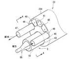
被検体内に挿入される挿入部23は、先端に設けられた硬質の先端部23dと、図示しないスコープ操作部21の操作によって湾曲動作を行う湾曲部と、柔軟性を有する可撓管などを備え、これらの部位は一列に連なるように構成されている。図3は、本発明にかかる超音波処置用医療装置の挿入部23の先端部23dにおける構成の実施の形態1を示す斜視図であり、図4は、図3のA−A断面を示す断面図である。これら図において、挿入部23の先端部23dには、先端に固定された照明系レンズからなる2つの照明窓40と、観察系レンズからなる1つの観察窓41と、一端が観察窓41に固定されたイメージガイドファイバ42とを備え、挿入部23内に設けられたイメージガイドファイバ42の他端は、ユニバーサルコード21a内を介して光源装置に接続されている。 The
照明窓40には、挿入部23内に設けられたライトガイドファイバの一端が設けられ、他端は、ユニバーサルコード21a内を介して光源装置に接続されている。この光源装置から出射された照明光を、ライトガイドファイバを通って、先端部23dの照明窓から外部、たとえば体腔内の被処置部に照射している。観察系レンズは、たとえば2枚のレンズ41a,41bで構成され、この体腔内の被処置部からの反射光を取り込んで、イメージガイドファイバ42に出射している。この出射された反射光は、イメージガイドファイバ42を通って、他端の表示装置に送られ、ここで被処置部の像を映し出すことにより、術者による被処置部の観察が可能となる。 One end of the light guide fiber provided in the
挿入部23の先端部23dには、複数のチャンネル、たとえば3つのチャンネル43〜45が形成されており、各チャンネル43〜45には、超音波処置具3、給水チューブ47、吸引チューブ48が突出可能に内設されている。すなわち、これらチャンネルのうちの処置具チャンネル43には、超音波処置具3が、給水チャンネル44には、給水チューブ47が、吸引チャンネル45には、吸引チューブ48がそれぞれ内設されている。 A plurality of channels, for example, three
超音波処置具3は、図1に示した操作部31と、図4の断面図に示す、先端に設けられた超音波振動子50と、この超音波振動子50を固定する円筒形状の硬性部材51と、超音波振動子50へ電気信号を入力させる信号線52と、超音波振動子50の後述する圧電素子および電極の水密を保つための隔壁53と、信号線52が挿入されて一端が硬性部材51と結合される可撓性シース54とから構成されている。なお、隔壁53は、硬性部材51と可撓性シース54の結合部に配置されている。また、可撓性シース54の他端は、操作部31に接続され、術者が可撓性シース54を手動で、ビデオスコープ2内に挿入したり、引き出したりすることで、挿入部23内を進退可能に移動している。たとえば、鉗子挿入口21fを介して内に可撓性シース54をビデオスコープ2内に挿入する。可撓性シース54を、挿入部23のチャンネル内を先端部23d方向に移動して、超音波振動子50と硬性部材51の一部を先端部23dから突出させ、超音波振動子50の超音波振動により処置を行う。また、この可撓性シース54を、挿入部23のチャンネル内を操作部21方向に移動させて、超音波振動子50と硬性部材51を先端部23d内に収納している。 The
超音波振動子50は、先端処置部50aと、超音波振動を先端処置部50aに伝達するホーン50bと、超音波振動子50を硬性部材51に固定するフランジ50cと、超音波振動を発生する圧電素子50dと、信号線52に接続されて圧電素子50dに電気信号を供給する電極50eと、裏打板50fとを備えている。この圧電素子50dには、信号線を介して上述した駆動装置6から電気信号が供給されており、圧電素子50dは、この電気信号を受けて超音波振動を発生する。発生した超音波振動は、絞り形状のホーン50bを通過することで、振動の振幅が拡大して、先端処置部50aに伝達される。フランジ50cは、振動の節位置に設けられ、硬性部材51の端部に固定される。 The
給水チューブ47は、可撓性の中空円筒管からなり、一端が先端部23dから突出可能に配置され、他端がスコープ操作部21を介して給水装置5に接続され、手動操作によって挿入部23内を進退可能に移動するように構成されている。たとえば、術者が、給水チューブ47をビデオスコープ2内に挿入すると、給水チューブ47が挿入部23の給水チャンネル44内を先端部23d方向に移動して、一端を先端部23dから突出させて、外部の給水装置5からの給水が可能になる。また、給水装置5からの給水を停止し、この給水チューブ47をビデオスコープ2内から引き出すと、給水チューブ47が挿入部23の給水チャンネル44内をスコープ操作部21方向に移動して、給水チューブ47を先端部23d内に収納する。このように、給水チューブ47は、給水チャンネル44を通して給水装置5から、生理食塩水や薬液などを体腔内の被処置部に供給することが可能となる。 The
吸引チューブ48は、可撓性の中空円筒管からなり、一端が先端部23dから突出可能に配置され、他端がスコープ操作部21を介して吸引装置4に接続され、手動操作によって挿入部23内を進退可能に移動するように構成されている。たとえば、術者が、吸引チューブ48をビデオスコープ2内に挿入すると、吸引チューブ48が挿入部23の吸引チャンネル45内を先端部23d方向に移動して、一端を先端部23dから突出させて、外部の吸引装置4による液体などの吸引が可能になる。また、吸引装置4による吸引を停止し、この吸引チューブ48をビデオスコープ2内から引き出すと、吸引チューブ48が挿入部23の吸引チャンネル45内をスコープ操作部21方向に移動して、吸引チューブ48を先端部23d内に収納する。このように、吸引チューブ48は、吸引チャンネル45を通して吸引装置4に、超音波処置具3の超音波処置により乳化・破砕した体組織や不要な体液などを排出することが可能となる。 The
操作部31は、図5に示すように、略円筒形状の操作部本体31aと、操作部本体31aの一端に設けられたリング部31bと、操作部本体31aの他端に設けられ、駆動装置6からの信号線52を可撓性シース54内に挿入するための二股の継手部31cと、操作部本体31aの側面に設けられ、駆動装置6からの電気信号供給および供給断を指示する指示ボタン31dとを備える。信号線52は、継手部31c内で屈曲され、可撓性シース36内に挿入されて、挿入部23先端に設けられた超音波振動子50と接続されており、これによって超音波振動子への電気信号の供給が可能になる。 As shown in FIG. 5, the
また、内視鏡装置1は、先端部23d近傍の挿入部23内に湾曲駒55を備える。この湾曲駒55は、上述した湾曲操作ノブ21bに接続されており、この湾曲操作ノブ21bを操作することで、内視鏡装置1の挿入部23の先端を屈曲させることが可能となる。 In addition, the endoscope apparatus 1 includes a
次に、この超音波処置用医療装置の超音波処置の動作を図6〜図9の図面に基づいて説明する。ここで、図6は、図3に示した先端部において、給水チューブを突出させた状態を示す斜視図、図7は、同じく先端部において、超音波処置具を突出させた状態を示す斜視図、図8は、同じく先端部において、吸引チューブを突出させた状態を示す斜視図、図9は、超音波処置用医療装置の超音波処置手順を説明するための図である。 Next, the operation of the ultrasonic treatment of this medical device for ultrasonic treatment will be described based on the drawings of FIGS. Here, FIG. 6 is a perspective view showing a state in which the water supply tube is projected from the distal end portion shown in FIG. 3, and FIG. 7 is a perspective view showing a state in which the ultrasonic treatment instrument is also projected from the distal end portion. 8 is a perspective view showing a state in which the suction tube is protruded at the distal end portion, and FIG. 9 is a view for explaining an ultrasonic treatment procedure of the medical device for ultrasonic treatment.
まず、先端部23dの照明窓40から外部に照明光が照射されている状態において、術者は、内視鏡装置1の挿入部23を、被検体の体腔内に挿入する。なお、この際には、給水チューブ47、吸引チューブ48および超音波処置具3は先端部23d内に収納された状態になっている。そして、挿入部23の先端部23dが体腔内の潰瘍などの被処置部に到ると、術者は、給水チューブ47をビデオスコープ2内に挿入する。この動作により、図6に示すように、給水チューブ47の一部が先端部23dから外部に突出するように移動し、さらに被処置部A近傍の所定位置まで給水チューブ47が突出される。次に、給水ボタン21hを押下すると、図9(a)に示すように、給水動作が開始されて給水装置5から給水チューブ47を介して生理食塩水を体腔内の被処置部Aに噴射する。そして、被処置部Aが所望の湿り気を有すると、給水ボタン21hの押下を解除して給水装置5からの給水を停止させ、給水チューブ47を後退させて、先端部23d内に収納する。 First, in a state where illumination light is irradiated from the
次に、術者は、可撓性シース54をビデオスコープ2内に挿入する。この操作により、図7に示すように、超音波処置具3の超音波振動子50を先端部23dから外部に突出させるように移動させる。さらに被処置部A近傍の所定位置まで超音波振動子50が突出されると、操作部31の指示ボタン31dをオン状態にする。これによって、駆動装置6から信号線を介して圧電素子50dに電気信号が供給されて、図9(b)に示すように、超音波振動子50の振動が発生する。この超音波振動によるキャビテーション効果により、被処置部Aの体組織は乳化もしくは破砕されることとなる。そして、被処置部A全体が所望の程度に乳化もしくは破砕されると、術者が、操作部31の指示ボタン31dをオフ状態に操作することで、操作部21は、超音波振動子50の超音波振動を停止させる。そして、可撓性シース54をビデオスコープ2から引き出して、超音波振動子50を先端部23d内に収納する。 Next, the operator inserts the
次に、術者は、吸引チューブ48をビデオスコープ2内に挿入する。この動作により、図8に示すように、吸引チューブ48の一部を先端部23dから外部に突出させることができ、さらに乳化もしくは破砕された被処置部の体組織B近傍の所定位置まで吸引チューブ48が突出されると、吸引ボタン21gを押されている状態から戻す。これにより、図9(c)に示すように、吸引装置4が吸引チューブ48を介して乳化もしくは破砕された体組織Bを吸引する。そして、この体組織Bの吸引が終了すると、吸引ボタン21gを押下することで、吸引動作を停止させ、吸引チューブ48をビデオスコープ2から引き出して、挿入部23の先端部23d内に収納する。術者は、これら一連の動作を観察窓41から送られてくる被処置部の像とともに観察しながら行うことができる。 Next, the surgeon inserts the
なお、この実施の形態では、給水チューブ47、吸引チューブ48および超音波振動子50を別々に外部に突出させるように動作させたが、本発明はこれに限らず、これらの全部または所望の2つを、必要な処置に応じて同時に突出させて動作させることも可能である。 In this embodiment, the
このように、この実施の形態では、超音波処置用医療装置の給水チューブ、吸引チューブおよび超音波振動子を、挿入部の先端部の各チャンネルから突出可能なように、前記挿入部に設け、必要な処置に応じて、これら給水チューブ、吸引チューブおよび超音波振動子を挿入部の先端部から適宜突出させて、所望の処置動作を行なわせるので、超音波振動による被検体内の体組織の乳化・破砕などの処置を容易に行うことができる。 As described above, in this embodiment, the water supply tube, the suction tube, and the ultrasonic transducer of the medical device for ultrasonic treatment are provided in the insertion portion so as to protrude from each channel of the distal end portion of the insertion portion, Depending on the necessary treatment, the water supply tube, the suction tube and the ultrasonic transducer are appropriately projected from the distal end of the insertion portion to perform a desired treatment operation. Treatment such as emulsification and crushing can be easily performed.
(実施の形態2)
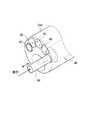
図10は、図1に示した超音波処置用医療装置の挿入部の先端部における構成の実施の形態2を示す斜視図であり、図11は、図10に示した先端部において、吸引チューブのみが突出した状態を示す斜視図である。なお、以下の図において、実施の形態1と同様の構成部分に関しては、説明の都合上、同一符号を付記するものとする。(Embodiment 2)
FIG. 10 is a perspective
この実施の形態2において、実施の形態1と異なる点は、挿入部23の先端部23dから突出した吸引チューブ48の一部が湾曲し、かつこの先端部の中心位置が偏心して、挿入部23の長手方向に直行している点と、吸引チューブ48が挿入部23の円周方向に回転する点である。 The second embodiment is different from the first embodiment in that a part of the
この吸引チューブ48の回転は、たとえば術者が、手動で吸引チューブ48を右回転または左回転させる操作を行うことで、吸引チューブ48が挿入部23の吸引チャンネル45内でこの回転に連動して、図11に図示した矢印のように右回転または左回転するものである。 The rotation of the
この実施の形態では、実施の形態1と同様の効果を奏するとともに、湾曲した吸引チューブ48の先端が回転するので、内視鏡装置1の先端部23dが屈曲によって移動する範囲よりも広い範囲で吸引動作を行うことができる。また、この実施の形態では、内視鏡装置1の先端部23dを屈曲させずに、すなわち観察する術者の視点を変えることなく、吸引場所を変更することが可能となって、正確に乳化あるいは破砕された体組織の吸引動作を行うことができる。 In this embodiment, the same effect as in the first embodiment is obtained, and the distal end of the
なお、本発明では、吸引チューブに限らず、給水チューブの一部を湾曲させ、かつこの先端部の中心位置が偏心して、挿入部23の長手方向に直行するとともに、給水チューブが挿入部の円周方向に回転するように構成することも可能である。 In the present invention, not only the suction tube but also a part of the water supply tube is curved, and the center position of the distal end portion is decentered and goes straight in the longitudinal direction of the
(実施の形態3)
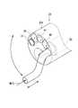
図12は、図1に示した超音波処置用医療装置の挿入部の先端部における構成の実施の形態3を示す斜視図であり、図13は、図12のB−B断面を示す断面図である。この実施の形態において、超音波処置具3は、実施の形態1と同様の硬性部材51、信号線52、隔壁53、可撓性シース54の他に、長手方向の中心軸に処置用管56を有する中空の超音波振動子50と、この処置用管56に接続される処置用チューブ57とを備える。(Embodiment 3)
12 is a perspective view showing a third embodiment of the configuration at the distal end portion of the insertion portion of the medical apparatus for ultrasonic treatment shown in FIG. 1, and FIG. 13 is a cross-sectional view showing a BB cross section of FIG. It is. In this embodiment, the
処置用管56は、先端処置部50aから裏打板50fまでの超音波振動子50の長手方向の中心軸上に開口した孔によって形成されており、処置用チューブ57は、一端がこの処置用管56の後端に接続され、他端が隔壁53を貫通して可撓性シース54内および操作部21を介して、吸引装置4に接続されている。この構成により、処置用管56から流入してくる乳化あるいは粉砕された体組織や不要な体液などは、処置用チューブ57を通過して、超音波処置用医療装置の外部に排出することが可能となる。 The
このように、この実施の形態では、超音波振動子内に処置用管を形成し、この処置用管を用いて体組織などを吸引して排出するので、吸引チャンネルが不要となり、より少ないチャンネル数で、超音波振動による被検体内の体組織の乳化・破砕などの処置を行うことができる。 As described above, in this embodiment, a treatment tube is formed in the ultrasonic transducer, and a body tissue or the like is sucked and discharged using the treatment tube, so that a suction channel is not required and fewer channels are provided. With a number, treatments such as emulsification and crushing of the body tissue in the subject by ultrasonic vibration can be performed.
なお、本発明は、これに限らず、たとえば適用する被処置部によっては、吸引チャンネルに吸引チューブを挿入し、処置用チューブ57を吸引装置の代わりに給水装置5に接続させて、処置用管56から生理食塩水や薬液などを供給するように構成することも可能である。 However, the present invention is not limited to this. For example, depending on the treatment target to be applied, a suction tube is inserted into the suction channel, and the
(実施の形態4)
図14は、図1に示した超音波処置用医療装置の挿入部の先端部における構成の実施の形態4を示す斜視図である。この実施の形態では、実施の形態2と3を組み合わせて挿入部の先端部を構成している。すなわち、この実施の形態では、挿入部23の先端部23dから突出した吸引チューブ48の一部が湾曲し、かつこの先端部の中心位置が偏心して、挿入部23の長手方向に直行するとともに、吸引チューブ48の先端が挿入部23の円周方向に回転するように構成している。さらに、この実施の形態では、処置用チューブ57を給水装置5に接続させて、処置用管56から外部(被処置部)に生理食塩水や薬液などを供給するように構成している。(Embodiment 4)
FIG. 14 is a perspective view showing Embodiment 4 of the configuration at the distal end portion of the insertion portion of the medical apparatus for ultrasonic treatment shown in FIG. In this embodiment, the distal end portion of the insertion portion is configured by combining the second and third embodiments. That is, in this embodiment, a part of the
このように、この実施の形態では、吸引チューブの先端を回転可能に構成するとともに、超音波振動子内に処置用管を形成して被処置部に給水を行うので、実施の形態1〜3と同様の効果を奏することができる。 As described above, in this embodiment, the distal end of the suction tube is configured to be rotatable, and a treatment tube is formed in the ultrasonic vibrator to supply water to the treated portion. The same effect can be achieved.
(付記1)
被処置部を観察可能な光学系および複数のチャンネルを有する内視鏡と、前記チャンネルに挿入可能な、先端に超音波振動子を装着した超音波処理具と、前記チャンネルに挿入可能な給水チューブおよび吸引チューブと、を備えたことを特徴とする超音波処置用医療装置。(Appendix 1)
An endoscope having an optical system capable of observing a treatment target part and a plurality of channels, an ultrasonic treatment tool having an ultrasonic transducer attached to the tip, which can be inserted into the channel, and a water supply tube which can be inserted into the channel And a medical device for ultrasonic treatment, comprising: a suction tube.
(付記2)
被処置部を観察可能な光学系および複数のチャンネルを有する内視鏡と、前記チャンネルに挿入可能な上に、先端に吸引管を有する中空超音波振動子を装着した超音波処置具と、前記チャンネルに挿入可能な給水チューブと、を備えたことを特徴とする超音波処置用医療装置。(Appendix 2)
An endoscope having a plurality of channels and an optical system capable of observing a treatment target; an ultrasonic treatment instrument equipped with a hollow ultrasonic transducer that can be inserted into the channel and has a suction tube at the tip; and A medical device for ultrasonic treatment, comprising a water supply tube that can be inserted into a channel.
(付記3)
付記1に記載の超音波処置用医療装置を用いた処置方法において、給水チューブから被検体内の被処置部に生理食塩水もしくは薬液を供給した後、超音波処置具による超音波振動で、前記被処置部を乳化および、または粉砕し、該乳化および、または粉砕した前記被検体内の組織を吸引チューブで吸引することを特徴とする超音波処置用医療装置を用いた処置方法。(Appendix 3)
In the treatment method using the medical device for ultrasonic treatment according to appendix 1, after supplying physiological saline or a chemical solution from a water supply tube to a treatment portion in a subject, ultrasonic vibration using an ultrasonic treatment tool, A treatment method using a medical device for ultrasonic treatment, wherein a treatment portion is emulsified and / or pulverized, and the emulsified and / or pulverized tissue in the subject is aspirated with a suction tube.
(付記4)
付記2に記載の超音波処置用医療装置を用いた処置方法において、給水チューブから被検体内の被処置部に生理食塩水もしくは薬液を供給した後、超音波処置具による超音波振動で、前記被処置部を乳化および、または粉砕し、該乳化および、または粉砕した前記被検体内の組織を前記超音波処置具に設けられた吸引管で吸引することを特徴とする超音波処置用医療装置の処置方法。(Appendix 4)
In the treatment method using the medical device for ultrasonic treatment according to
1 内視鏡装置
2 ビデオスコープ
3 超音波処置具
4 吸引装置
5 給水装置
6 駆動装置
21 スコープ操作部
21a ユニバーサルコード
21b 湾曲操作ノブ
21c 吸引挿入口
21d 給水挿入口
21e 把持部
21f 鉗子挿入口
21g 吸引ボタン
21h 給水ボタン
23 挿入部
23d 先端部
31 操作部
31a 操作部本体
31b リング部
31c 継手部
31d 指示ボタン
36 可撓性シース
40 照明窓
41 観察窓
41a,41b レンズ
42 イメージガイドファイバ
43 処置具チャンネル
44 給水チャンネル
45 吸引チャンネル
47 給水チューブ
48 吸引チューブ
50 超音波振動子
50a 先端処置部
50b ホーン
50c フランジ
50d 圧電素子
50e 電極
50f 裏打板
51 硬性部材
52 信号線
53 隔壁
54 可撓性シース
55 湾曲駒
56 処置用管
57 処置用チューブ
A 被処置部
B 体組織
DESCRIPTION OF SYMBOLS 1
Claims (7)
Translated fromJapanese前記挿入部の先端部に設けられ、超音波振動を発生する超音波振動子と、
前記挿入部の先端部に、該先端部から突出可能に設けられ、前記超音波振動子からの超音波振動を前記被検体の被処置部へ伝達する振動伝達手段と、
前記挿入部の先端部に設けられ、前記被処置部を照明光で照明する照明手段および前記被処置部を観察可能な観察手段と、
前記挿入部の先端部に、該先端部から突出可能に設けられ、前記被処置部への給水を行う給水手段と、
前記挿入部の先端部に、該先端部から突出可能に設けられ、前記被処置部から吸引を行う吸引手段と、
を備えることを特徴とする超音波処置用医療装置。An endoscope having an insertion portion that can be inserted into a body cavity of a subject;
An ultrasonic transducer that is provided at the distal end of the insertion portion and generates ultrasonic vibrations;
Vibration transmitting means provided at the distal end portion of the insertion portion so as to be able to project from the distal end portion, and transmitting ultrasonic vibration from the ultrasonic transducer to the treatment target portion of the subject;
An illuminating unit that is provided at a distal end of the insertion unit and that illuminates the treated part with illumination light; and an observing unit capable of observing the treated part;
A water supply means provided at the distal end of the insertion portion so as to be able to protrude from the distal end, and for supplying water to the treated portion;
A suction means provided at the distal end portion of the insertion portion so as to be able to project from the distal end portion, and performing suction from the treated portion;
A medical device for ultrasonic treatment, comprising:
Priority Applications (1)
| Application Number | Priority Date | Filing Date | Title |
|---|---|---|---|
| JP2004004767AJP2005192945A (en) | 2004-01-09 | 2004-01-09 | Medical apparatus for ultrasonic treatment |
Applications Claiming Priority (1)
| Application Number | Priority Date | Filing Date | Title |
|---|---|---|---|
| JP2004004767AJP2005192945A (en) | 2004-01-09 | 2004-01-09 | Medical apparatus for ultrasonic treatment |
Publications (1)
| Publication Number | Publication Date |
|---|---|
| JP2005192945Atrue JP2005192945A (en) | 2005-07-21 |
Family
ID=34819286
Family Applications (1)
| Application Number | Title | Priority Date | Filing Date |
|---|---|---|---|
| JP2004004767APendingJP2005192945A (en) | 2004-01-09 | 2004-01-09 | Medical apparatus for ultrasonic treatment |
Country Status (1)
| Country | Link |
|---|---|
| JP (1) | JP2005192945A (en) |
Cited By (4)
| Publication number | Priority date | Publication date | Assignee | Title |
|---|---|---|---|---|
| WO2007105495A1 (en) | 2006-03-13 | 2007-09-20 | Olympus Medical Systems Corp. | Scattering medium inside observing device, imaging system, imaging method, and endoscope |
| JP2014166222A (en)* | 2013-02-28 | 2014-09-11 | Olympus Corp | Cavitation generator |
| CN105342545A (en)* | 2015-12-01 | 2016-02-24 | 刘薇 | Hysteroscope |
| KR20230067815A (en)* | 2021-11-09 | 2023-05-17 | 주식회사 로엔서지컬 | Endoscope apparatus for calculus removing |
- 2004
- 2004-01-09JPJP2004004767Apatent/JP2005192945A/enactivePending
Cited By (6)
| Publication number | Priority date | Publication date | Assignee | Title |
|---|---|---|---|---|
| WO2007105495A1 (en) | 2006-03-13 | 2007-09-20 | Olympus Medical Systems Corp. | Scattering medium inside observing device, imaging system, imaging method, and endoscope |
| US8259167B2 (en) | 2006-03-13 | 2012-09-04 | Olympus Medical Systems Corp. | Scattering medium internal observation apparatus, image pickup system, image pickup method and endoscope apparatus |
| JP2014166222A (en)* | 2013-02-28 | 2014-09-11 | Olympus Corp | Cavitation generator |
| CN105342545A (en)* | 2015-12-01 | 2016-02-24 | 刘薇 | Hysteroscope |
| KR20230067815A (en)* | 2021-11-09 | 2023-05-17 | 주식회사 로엔서지컬 | Endoscope apparatus for calculus removing |
| KR102684546B1 (en) | 2021-11-09 | 2024-07-15 | 주식회사 로엔서지컬 | Endoscope apparatus for calculus removing |
Similar Documents
| Publication | Publication Date | Title |
|---|---|---|
| Wuchinich et al. | Endoscopic ultrasonic rotary electro-cauterizing aspirator | |
| EP0659387B1 (en) | Ultrasonic diagnosis and therapy system in which focusing point of therapeutic ultrasonic wave is locked at predetermined position within observation ultrasonic scanning range | |
| CN102843983B (en) | For cutting the dual-purpose surgical instruments with solidified structure | |
| JP4472759B2 (en) | Ultrasonic treatment device | |
| US7922651B2 (en) | Ultrasonic treatment apparatus, endoscope apparatus, and treatment method | |
| US5471988A (en) | Ultrasonic diagnosis and therapy system in which focusing point of therapeutic ultrasonic wave is locked at predetermined position within observation ultrasonic scanning range | |
| US7258668B2 (en) | Ultrasonic probe for operation under microscope | |
| US5492126A (en) | Probe for medical imaging and therapy using ultrasound | |
| JP2004000336A (en) | Ultrasonic treatment apparatus | |
| EP1977681B1 (en) | Treatment instrument system | |
| JP3594278B2 (en) | Intracavity ultrasonic probe device | |
| JP2911689B2 (en) | Surgical handpiece | |
| BR112012020296B1 (en) | Ultrasonic surgical instrument | |
| JPH11276422A (en) | Ultrasonic endoscope | |
| JP2005046424A (en) | Ultrasonic treatment apparatus | |
| JPH08275951A (en) | Ultrasonic dissecting and coagulating device | |
| WO2017013813A1 (en) | Ultrasound treatment tool and ultrasound treatment assembly | |
| JP2008161570A (en) | Ultrasound endoscope system | |
| JP3850094B2 (en) | Ultrasound diagnostic treatment system and treatment adapter | |
| JP2015058234A (en) | Medical liquid injection device | |
| JP2000287986A (en) | Tool for surgical implement | |
| JPH07227395A (en) | Ultrasonic diagnostic and curing system | |
| JP2005192945A (en) | Medical apparatus for ultrasonic treatment | |
| JPH11299789A (en) | Ultrasonic probe in body cavity | |
| JP2001025467A (en) | Ultrasonic spray tube |
Legal Events
| Date | Code | Title | Description |
|---|---|---|---|
| A621 | Written request for application examination | Free format text:JAPANESE INTERMEDIATE CODE: A621 Effective date:20050901 | |
| A977 | Report on retrieval | Free format text:JAPANESE INTERMEDIATE CODE: A971007 Effective date:20071121 | |
| A131 | Notification of reasons for refusal | Free format text:JAPANESE INTERMEDIATE CODE: A131 Effective date:20071204 | |
| A521 | Written amendment | Free format text:JAPANESE INTERMEDIATE CODE: A523 Effective date:20080204 | |
| A131 | Notification of reasons for refusal | Free format text:JAPANESE INTERMEDIATE CODE: A131 Effective date:20080304 | |
| A521 | Written amendment | Free format text:JAPANESE INTERMEDIATE CODE: A523 Effective date:20080425 | |
| A02 | Decision of refusal | Free format text:JAPANESE INTERMEDIATE CODE: A02 Effective date:20080603 |