JP2005192738A - Endoscope device - Google Patents
Endoscope deviceDownload PDFInfo
- Publication number
- JP2005192738A JP2005192738AJP2004001126AJP2004001126AJP2005192738AJP 2005192738 AJP2005192738 AJP 2005192738AJP 2004001126 AJP2004001126 AJP 2004001126AJP 2004001126 AJP2004001126 AJP 2004001126AJP 2005192738 AJP2005192738 AJP 2005192738A
- Authority
- JP
- Japan
- Prior art keywords
- loading
- endoscope
- unit
- section
- battery
- Prior art date
- Legal status (The legal status is an assumption and is not a legal conclusion. Google has not performed a legal analysis and makes no representation as to the accuracy of the status listed.)
- Withdrawn
Links
- 238000005452bendingMethods0.000claimsdescription21
- 238000003780insertionMethods0.000claimsdescription20
- 230000037431insertionEffects0.000claimsdescription20
- 238000005286illuminationMethods0.000claimsdescription10
- 210000003813thumbAnatomy0.000description6
- 210000000078clawAnatomy0.000description5
- 238000003384imaging methodMethods0.000description4
- 210000001124body fluidAnatomy0.000description2
- 239000010839body fluidSubstances0.000description2
- 238000007689inspectionMethods0.000description2
- 238000000034methodMethods0.000description2
- XLYOFNOQVPJJNP-UHFFFAOYSA-NwaterSubstancesOXLYOFNOQVPJJNP-UHFFFAOYSA-N0.000description2
- 210000001015abdomenAnatomy0.000description1
- 238000004891communicationMethods0.000description1
- 210000003811fingerAnatomy0.000description1
- 239000007788liquidSubstances0.000description1
- 238000012856packingMethods0.000description1
- 230000002093peripheral effectEffects0.000description1
- 210000000707wristAnatomy0.000description1
Images


Landscapes
- Instruments For Viewing The Inside Of Hollow Bodies (AREA)
- Endoscopes (AREA)
- Studio Devices (AREA)
Abstract
Description
Translated fromJapanese本発明は、小型の映像表示装置が一体になって携帯に適した内視鏡装置に関する。 The present invention relates to an endoscope apparatus that is compact and suitable for carrying with a small image display device.
医療分野や工業分野で広く用いられている内視鏡装置には、接眼部にあたる部分にケーブルを介して据え置き型のテレビモニタを接続し、内視鏡で得た像をCCD等の撮像素子の受光部に結像させ、結像させた像を信号に変換し、信号に変換した像をケーブルを介して離れた位置にあるテレビモニタに供給し、その画面上に映像化して表示させるようにしたものがある。
また、内視鏡で得た像をCCD等の撮像素子の受光部に結像させ、結像させた像を信号に変換し、信号に変換した像をテレビモニタに供給し、その画面上に映像化して表示させるようにしたものがある(例えば下記の特許文献1)。この内視鏡装置には、光源装置に小型のバッテリが内蔵されており、光源ランプに電力を供給するだけでなく、内視鏡側の電力を必要とする各部にも電力供給を行うようになっている。
さらに、表示画面が内視鏡の操作部に接続された携帯用の内視鏡装置も提案されている(例えば下記の特許文献2)。
In addition, an image obtained by the endoscope is formed on a light receiving portion of an image sensor such as a CCD, the formed image is converted into a signal, and the image converted into a signal is supplied to a television monitor and is displayed on the screen. There is one that is displayed as a video (for example,
Furthermore, a portable endoscope apparatus in which a display screen is connected to an operation unit of the endoscope has also been proposed (for example,
上記のような従来の内視鏡装置において、術者は通常左手で内視鏡を持ち、右手で挿入部を持って内視鏡装置を操作するが、上記の内視鏡装置に、テレビモニタを駆動するためのバッテリや撮像素子によって撮像された画像を記録する記録媒体を着脱自在に装填できるような構造を採用する場合、新たに設けられる各部の操作を、術者が内視鏡装置を持った状態で如何に行い易くするかが問題となっている。 In the conventional endoscope apparatus as described above, the operator usually holds the endoscope with the left hand and operates the endoscope apparatus with the insertion portion with the right hand. When adopting a structure in which a recording medium for recording an image picked up by a battery or an image pickup device can be detachably loaded, the operator can change the operation of each newly provided part by the operator. The problem is how to make it easier to hold it.
本発明は上記の事情に鑑みてなされたものであり、バッテリや記録媒体を着脱自在に装填できる装填部が、内視鏡装置を持った状態であっても術者にとって操作し易い内視鏡装置を提供することを目的としている。 The present invention has been made in view of the above circumstances, and an endoscope that is easy for a surgeon to operate even when a loading unit capable of detachably loading a battery or a recording medium has an endoscope device. The object is to provide a device.
上記の課題を解決するための手段として、次のような構成の内視鏡装置を採用する。
すなわち請求項1記載の内視鏡装置は、被検体の体腔内に挿入可能な挿入部と、前記挿入部に設けられた湾曲部と、前記挿入部の基端部に接続された内視鏡ユニットと、前記内視鏡ユニットに対して、前記湾曲部を操作するための操作用部材を、回動軸を中心に回動自在に取り付ける取り付け部と、前記取り付け部側に設けられ、前記回動軸方向に開口する開口部を備えた、前記内視鏡ユニットに装填部材を着脱自在に装填可能な装填部とを備えたことを特徴とする。As means for solving the above problems, an endoscope apparatus having the following configuration is employed.
That is, the endoscope apparatus according to
湾曲部を操作する操作用部材は、頻繁に操作されるために操作し易い側に設けられている。そこで本発明においては、装填部が、頻繁に操作される操作用部材の取り付け部側、すなわち操作し易い側に設けられているので、装填部の操作が行い易くなる。
例えば、術者が左手で内視鏡ユニットを持ち、左手の親指で操作用部材を操作するとき、装填部の開口部は操作用部材の回動軸方向、すなわち右方向に開口するから、装填部に装填部材を出し入れする操作を、内視鏡ユニットを持たない右手を使って支障なく行うことができる。The operation member for operating the bending portion is provided on the side that is easy to operate because it is frequently operated. Therefore, in the present invention, the loading portion is provided on the side where the operation member that is frequently operated is attached, that is, on the side that is easy to operate, so that the loading portion can be easily operated.
For example, when the operator holds the endoscope unit with the left hand and operates the operation member with the thumb of the left hand, the opening of the loading portion opens in the direction of the rotation axis of the operation member, that is, the right direction. The operation of inserting and removing the loading member into and from the unit can be performed without any trouble using the right hand that does not have the endoscope unit.
請求項2記載の内視鏡装置は、被検体の体腔内に挿入可能な挿入部と、前記挿入部の先端部に設けられた対物レンズと、前記挿入部の基端部に接続された内視鏡ユニットと、前記対物レンズにて観察する際に被検体の体腔内を照明するための照明光を供給する、前記内視鏡ユニットに取り付けられた光源装置と、前記光源装置の反対側に設けられ、前記内視鏡ユニットに装填部材を着脱自在に装填可能な装填部とを備えたことを特徴とする。 The endoscope apparatus according to
光源装置は、内視鏡の操作にあまり影響を与えないので、操作し易い側とは反対側、すなわち操作し難い側に設けられている。そこで本発明においては、装填部が、内視鏡の操作にあまり影響を与えない光源装置の反対側、すなわち操作し易い側に設けられているので、装填部の操作が行い易くなる。 Since the light source device does not significantly affect the operation of the endoscope, the light source device is provided on the side opposite to the side that is easy to operate, that is, the side that is difficult to operate. Therefore, in the present invention, since the loading unit is provided on the opposite side of the light source device that does not significantly affect the operation of the endoscope, that is, on the side that is easy to operate, the loading unit can be easily operated.
請求項3記載の内視鏡装置は、請求項1または請求項2記載の内視鏡装置において、前記装填部に設けられ、少なくとも1つ以上の装填部材を装填可能な装填口と、前記装填口のすべてを覆う装填口カバー部材とを備えることを特徴とする。 The endoscope apparatus according to
本発明においては、装填口のすべてを覆う装填口カバー部材が設けられているので、装填部材を装填する開口部が複数設けられている場合でも、装填口カバー部材の開け閉めが一回の動作で行え、操作が煩雑にならない。 In the present invention, since the loading port cover member that covers all the loading ports is provided, even when a plurality of openings for loading the loading member are provided, the opening and closing of the loading port cover member is performed once. The operation is not complicated.
本発明の内視鏡装置によれば、バッテリや記録媒体を着脱自在に装填できる装填部が、内視鏡装置を持った状態であっても術者にとって操作し易い位置にあるので、内視鏡装置を使用中の術者の負担を少なくし、内視鏡装置の操作を楽に使用することができる。 According to the endoscope apparatus of the present invention, since the loading unit capable of detachably loading the battery and the recording medium is in a position that is easy for the operator to operate even when the endoscope apparatus is held, The burden on the operator who is using the mirror device can be reduced, and the operation of the endoscope device can be used easily.
本発明の実施形態を図1ないし図5に示して説明する。
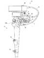
図1ないし図3に示す本実施形態の内視鏡装置は、内視鏡1と、被写体を照らす照明光を発する光源装置2と、内視鏡1で得た被写体の像を映像化して表示する映像表示装置3とを主要な構成要素として備えている。
内視鏡1は、先端を観察部位に挿入される挿入部11と、挿入部11の先端を湾曲操作するための操作部(取り付け部)12とを備えている。また、内視鏡1には、後述するイメージガイド11bによって導かれた像(光)を受光するCCD等の撮像素子4と、撮像素子4の受光部に結像する集光レンズ4aとが設けられている。挿入部11は、可撓性を有する細長い形状で、操作部12の一端に接続されており、先端に位置する硬質な先端部16と、先端部16に連続して設けられた湾曲部17と、湾曲部17に連続して設けられて操作部12に接続された可撓部18とを備えている。先端部16には、照明光に照らされた被写体からの反射光による像を結像する対物レンズ19と、照明光を出射する照明窓16aとが設けられている。湾曲部17および可撓部18には、光源装置2から先端部16に照明光を導くライトガイド11aと、対物レンズ19に結像された像を撮像素子4に導くイメージガイド11bとが内蔵されている。なお、撮像素子4は、図に示すように映像表示装置3に近い位置に設けられる場合と、先端部16に設けられる場合とがある。An embodiment of the present invention will be described with reference to FIGS.
The endoscope apparatus of this embodiment shown in FIGS. 1 to 3 visualizes and displays an
The
操作部12は、術者が内視鏡1を把持するための把持部10と、挿入部11に通された2本のワイヤ11cを介して湾曲部17を所望の方向に湾曲させるための湾曲操作レバー(操作用部材)20とを備えている。把持部10は、一般に左手で把持し易い構成となっており、棒状で親指とその他の指とで包み込むように握ることができる形に形成されている。把持部10には、体液等の液体を吸引するための吸引口金13と、鉗子等の処置具を挿入するための鉗子挿入口14と、内視鏡1の水漏れ検査時に内視鏡1内部に空気を送るための通気口金15とが設けられている。吸引口金13には、図示しないチューブを介して吸引装置が接続されるようになっており、吸引装置を作動させることにより吸引口金13を通じて体液等を吸引することができるようになっている。通気口金15には、図示しないチューブを介して給気装置が接続されるようになっており、給気装置を作動させることにより通気口金15から内視鏡1に空気を送り込み、内視鏡1内部の水漏れ検査を行うことができるようになっている。また、操作部12には、映像表示装置3に表示されている映像を後述する画像記録装置32に記録させる画像記録スイッチ32bが設けられている。 The
湾曲操作レバー20は、把持部10を握った手の親指で操作できるように把持部10に隣接して設けられている。湾曲操作レバー20は、把持部10を掴んだ親指の腹で操作される先端部20aと、先端部20aの一端に繋がる基端部20bとからなるL字形で、操作部12に設けられた軸12aに基端部20bを軸支されて上下に揺動可能に支持されている。湾曲操作レバー20は、先端部20aを親指で上下に押し引きすることでいずれか一方のワイヤ11cに張力を、他方のワイヤ11cに推力を作用させて湾曲部17を自在に湾曲させることができるようになっている。 The bending operation lever 20 is provided adjacent to the
光源装置2は、光源ランプ21と、術者が任意に光源ランプ21を点灯/滅灯させるための手許スイッチ22と、光源ランプ21が発した照明光を集光する集光レンズ23とを備えている。また、光源装置2には、後述する給電ケーブル6を着脱可能に接続されるコネクタ2aが設けられている。光源ランプ21、手許スイッチ22およびコネクタ2aは、光源装置2に内蔵された給電ライン2bによって直列に接続されている。
光源ランプ21が発した照明光は、集光レンズ23によって集光され、ライトガイド11aに導かれて照明窓16aから出射され、体腔内を照明するようになっている。The
Illumination light emitted from the
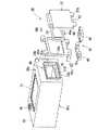
映像表示装置3は、操作部12の他端に着脱可能に取り付けられている。映像表示装置3は、筐体30の内部に、被写体の観察像を映像化して表示させるLCD等の表示素子31と、被写体の像をメモリカード等の記録媒体(装填部材)に記録する画像記録装置32と、撮像素子4で撮像された被写体の像を信号化して出力する撮像素子制御回路33と、撮像素子制御回路33から出力された信号を映像化して表示素子31に表示させる表示素子制御回路34とが内蔵されている。映像表示装置3の内部には、光源装置2、撮像素子4、映像表示装置3の各部に電力を供給するバッテリ(同じく装填部材)5が、着脱可能に内蔵されている。バッテリ5には、繰り返し充電して使用することができる二次電池が使用されている。また、表示素子31の画面脇の筐体30には、内視鏡装置を起動または停止させる起動スイッチ35が設けられている。 The
さらに、筐体30の内部には、バッテリ5および記録媒体32Aを映像表示装置3に装填するための装填部40が設けられている。装填部40は、図4に示すように、映像表示装置3の画面を正面に見据えたときに画面の中央よりも右側、すなわち操作部12側に設けられており、バッテリ5を出し入れする開口部41Aと、記録媒体32Aを出し入れする開口部41Bとを備えている。開口部41A,41Bは、いずれも操作部12から右向きに突き出している回動軸12aの軸方向に開口しており、バッテリ5および記録媒体32Aは回動軸12aの軸方向に沿って出し入れできるようになっている。 Furthermore, a
筐体30には、装填部40の開口部41A,41Bを露出させ、バッテリ5および記録媒体32Aを装填可能とする装填口36が設けられている。装填口36は、映像表示装置3の画面を正面に見据えたときに画面の中央よりも右側、すなわち操作部12側に設けられており、筐体30の右側面の大部分を四角く切除したように形成されている。装填口36には、装填口36のすべてを覆う蓋体(装填口カバー部材)37が設けられている。蓋体37は、装填口36の形状に合致するように四角形状をなしており、表示素子31の画面が露出する筐体30の上面30aと、筐体30の右側面30bとが接する稜線の部分に設けられたヒンジ部38を介し、筐体30に対して開閉自在に連結されている。ヒンジ部38は、筐体30の右側面30bに接着された座板38aに、蓋体37がピン38bを介して連結されることで回動自在に支持された構造を有している。 The
筐体30の下面30cには、蓋体37をロックして蓋体37の予期せぬ開放を防止するロック機構42が設けられている。ロック機構42は、ヒンジ部38に連結された蓋体37の一方の側縁37aと平行な他方の側縁37bに設けられた爪部43に対し、筐体30の下面30cに設けられて爪部43に係合可能な凹部44を有する係合部45と、爪部43に係合した係合部45を筐体30側に引き付けて定位置に固定するレバー46とを備えている。レバー46は、座板38aに、ピン46aを介して連結されることで回動自在に支持されており、係合部45は、レバー46に、ピン45aを介して連結されることで回転自在に支持されている。 A
また、装填口36の周囲には、装填口36の縁に沿って突き出した突条部30dが形成されており、蓋体37には、突条部30dの内側に嵌め込まれるように膨出部37aが形成されている。そして、膨出部37aの周囲には、蓋体37を閉じたときに突条部30dの内周面に押し当てられて装填口36を密封する環状のパッキン39が取り付けられている。 Further, a protruding
内視鏡1の上部にはブラケット1bが設けられ、映像表示装置3の下部にもブラケット3aが設けられており、これら2つのブラケット1b,3aは、締め付け用のネジ8によって締結されている。映像表示装置3は、ネジ8を緩めることにより画面の向きを湾曲操作レバー20側に傾斜させることができ、可動範囲内の所望の位置でネジ8を締めることにより固定することができるようになっている。 A
映像表示装置3と光源装置2とは、後述する給電ライン21aを内包する給電ケーブル6を介して接続されている。映像表示装置3と内視鏡1とは、後述する給電ライン4bおよび通信ラインS1を内包する集合ケーブル7を介して接続されている。給電ケーブル6および集合ケーブル7は、いずれも映像表示装置3側に固定され、先端にはそれぞれコネクタ6a,7aが設けられている。コネクタ6aは光源装置2のコネクタ2aに着脱可能に接続され、コネクタ7aは内視鏡1のコネクタ1aに着脱可能に接続されるようになっている。 The
上記のように構成された内視鏡装置において、映像表示装置3からバッテリ5や記録媒体32Aを取り出す場合の操作を、図5に示して説明する。
まず、術者は、右手を使い、レバー46を筐体30の下面30cから離間させるように回動させる。これにより、爪部43に係合して蓋体37を固定していた係合部45が蓋体37側に移動し、係合部45と爪部43との係合が解除され、蓋体37はヒンジ部38を介して回動自在に支持された状態となる。次に術者は、同じく右手を使って蓋体37を筐体30の右側面30bから離間させる方向に開き、装填口36を大きく露出させる。装填口36の内側には、開口部41Aから装填部40にバッテリ5が装填され、開口部41Bから装填部40に記録媒体32Aが装填されている。そこで術者は、同じく右手を使い、図示しないイジェクトボタンを押す等してバッテリ5、記録媒体32Aを装填口36から突き出させ、やはり右手を使って装填部40からバッテリ5、記録媒体32Aを取り出す。In the endoscope apparatus configured as described above, an operation for removing the
First, the operator uses the right hand to rotate the
映像表示装置3にバッテリ5や記録媒体32Aを装填する場合の操作は、上記の手順の逆を辿ればよい。まず、術者は、右手を使い、蓋体37を開いて露出させた装填口36を通じ、開口部41Aにバッテリ5を、開口部41Bに記録媒体32Aをそれぞれ差し込み、奥まで完全に挿入する。次に術者は、同じく右手を使って蓋体37を筐体30の右側面30bに密着させるように閉じ、装填口36をすべて蓋体37によって覆う。次に術者は、同じく右手を使って係合部45を爪部43に係合させ、さらにレバー46を筐体30の下面30cに密着させるように回動させる。これにより、蓋体37が筐体30の右側面30cに密着した状態で固定される。 The operation for loading the
本実施形態の内視鏡装置によれば、術者が左手で内視鏡1を持ち、左手の手首を無理に曲げることなく自然な角度に保ったうえで、左手の親指を使って湾曲操作レバー20を操作するとき、装填部40の開口部41A,41Bはいずれも湾曲操作レバー20の回動軸12a方向、すなわち術者の右方向に開口する。この状態では、装填部40にバッテリ5や記録媒体32Aを出し入れする操作を、内視鏡1を持たない右手だけを使って支障なく行うことができる。また、バッテリ5の装填部、記録媒体32Aの装填部それぞれに蓋体が設けられているのと違い、バッテリ5や記録媒体32Aを取り出すための蓋体37の開け閉めが一回の動作で行え、操作が煩雑にならない。
したがって、内視鏡装置を使用中の術者の負担を少なくし、内視鏡装置の操作を楽に使用することができる。According to the endoscope apparatus of the present embodiment, the operator holds the
Therefore, the burden on the operator who is using the endoscope apparatus can be reduced, and the operation of the endoscope apparatus can be used easily.
ところで、本実施形態では内視鏡装置を構成する映像表示装置3に装填部40を設けているが、内視鏡1と映像表示装置3とがブラケット等で連結されることなく一体になって内視鏡ユニットを構成する場合、装填部40は映像表示装置3に相当する部分に設けられても、内視鏡1に相当する部分に設けられても構わない。 By the way, in this embodiment, although the
本発明の内視鏡装置は、上記のような医療用だけでなく工業用にも好適に利用することが可能である。 The endoscope apparatus of the present invention can be suitably used not only for medical use as described above but also for industrial use.
1 内視鏡
2 光源装置
3 映像表示装置
5 バッテリ(装填部材)
11 挿入部
12 操作部(取り付け部)
12a 回動軸
17 湾曲部
19 対物レンズ
20 湾曲操作レバー(操作用部材)
31 表示素子
32 画像記録装置
32A 記録媒体(装填部材)
35 起動スイッチ
36 装填口
37 蓋体(装填口カバー部材)
40 装填部
41A,41B 開口部
DESCRIPTION OF
11
31
35
40
Claims (3)
Translated fromJapanese前記挿入部に設けられた湾曲部と、
前記挿入部の基端部に接続された内視鏡ユニットと、
前記内視鏡ユニットに対して、前記湾曲部を操作するための操作用部材を、回動軸を中心に回動自在に取り付ける取り付け部と、
前記取り付け部側に設けられ、前記回動軸方向に開口する開口部を備えた、前記内視鏡ユニットに装填部材を着脱自在に装填可能な装填部と
を備えたことを特徴とする内視鏡装置。An insertion section that can be inserted into the body cavity of the subject;
A bending portion provided in the insertion portion;
An endoscope unit connected to a proximal end portion of the insertion portion;
An attachment portion for attaching an operation member for operating the bending portion to the endoscope unit so as to be rotatable about a rotation axis;
An endoscope comprising: a loading portion that is provided on the attachment portion side and includes an opening that opens in the direction of the rotation axis; and a loading portion that can removably load a loading member on the endoscope unit. Mirror device.
前記挿入部の先端部に設けられた対物レンズと、
前記挿入部の基端部に接続された内視鏡ユニットと、
前記対物レンズにて観察する際に被検体の体腔内を照明するための照明光を供給する、前記内視鏡ユニットに取り付けられた光源装置と、
前記光源装置の反対側に設けられ、前記内視鏡ユニットに装填部材を着脱自在に装填可能な装填部と
を備えたことを特徴とする内視鏡装置。An insertion section that can be inserted into the body cavity of the subject;
An objective lens provided at the distal end of the insertion portion;
An endoscope unit connected to a proximal end portion of the insertion portion;
A light source device attached to the endoscope unit for supplying illumination light for illuminating the body cavity of the subject when observing with the objective lens;
An endoscope apparatus comprising: a loading portion provided on the opposite side of the light source device and capable of detachably loading a loading member on the endoscope unit.
前記装填口のすべてを覆う装填口カバー部材と
を備えることを特徴とする請求項1または請求項2記載の内視鏡装置。
A loading port provided in the loading unit and capable of loading at least one loading member;
The endoscope apparatus according to claim 1, further comprising a loading port cover member that covers all of the loading port.
Priority Applications (1)
| Application Number | Priority Date | Filing Date | Title |
|---|---|---|---|
| JP2004001126AJP2005192738A (en) | 2004-01-06 | 2004-01-06 | Endoscope device |
Applications Claiming Priority (1)
| Application Number | Priority Date | Filing Date | Title |
|---|---|---|---|
| JP2004001126AJP2005192738A (en) | 2004-01-06 | 2004-01-06 | Endoscope device |
Publications (1)
| Publication Number | Publication Date |
|---|---|
| JP2005192738Atrue JP2005192738A (en) | 2005-07-21 |
Family
ID=34816735
Family Applications (1)
| Application Number | Title | Priority Date | Filing Date |
|---|---|---|---|
| JP2004001126AWithdrawnJP2005192738A (en) | 2004-01-06 | 2004-01-06 | Endoscope device |
Country Status (1)
| Country | Link |
|---|---|
| JP (1) | JP2005192738A (en) |
Cited By (3)
| Publication number | Priority date | Publication date | Assignee | Title |
|---|---|---|---|---|
| JP2007144123A (en)* | 2005-10-24 | 2007-06-14 | Pentax Corp | Intubation support device |
| WO2017126161A1 (en)* | 2016-01-20 | 2017-07-27 | オリンパス株式会社 | Endoscope |
| WO2017126162A1 (en)* | 2016-01-20 | 2017-07-27 | オリンパス株式会社 | Portable endoscope |
- 2004
- 2004-01-06JPJP2004001126Apatent/JP2005192738A/ennot_activeWithdrawn
Cited By (7)
| Publication number | Priority date | Publication date | Assignee | Title |
|---|---|---|---|---|
| JP2007144123A (en)* | 2005-10-24 | 2007-06-14 | Pentax Corp | Intubation support device |
| WO2017126161A1 (en)* | 2016-01-20 | 2017-07-27 | オリンパス株式会社 | Endoscope |
| WO2017126162A1 (en)* | 2016-01-20 | 2017-07-27 | オリンパス株式会社 | Portable endoscope |
| JP6246423B1 (en)* | 2016-01-20 | 2017-12-13 | オリンパス株式会社 | Endoscope |
| JP6266173B2 (en)* | 2016-01-20 | 2018-01-24 | オリンパス株式会社 | Portable endoscope |
| CN108471929A (en)* | 2016-01-20 | 2018-08-31 | 奥林巴斯株式会社 | Portable endoscope |
| US11089942B2 (en) | 2016-01-20 | 2021-08-17 | Olympus Corporation | Portable endoscope having video display device offset relative to longitudinal axis of operation portion |
Similar Documents
| Publication | Publication Date | Title |
|---|---|---|
| JP4365860B2 (en) | Endoscope device | |
| US8142346B2 (en) | Endoscope with electromagnetic wave shield | |
| US8303489B2 (en) | Endoscope with built-in filtering means | |
| JP7114618B2 (en) | Endoscope | |
| US8075475B2 (en) | Endoscope system and medical instrument | |
| EP2119391A2 (en) | Medical operation device | |
| JP5484763B2 (en) | Endoscope device and endoscope display device | |
| JP2007105395A (en) | Endoscope | |
| JP2005192738A (en) | Endoscope device | |
| JP7098744B2 (en) | Endoscopic treatment tools, endoscopic auxiliary tools and endoscopes | |
| JPH0747052A (en) | Cover type endoscope | |
| JP2005192931A (en) | Endoscope device | |
| JP2000131623A (en) | Endoscopic device | |
| JP4624834B2 (en) | Endoscope device | |
| JP3971400B2 (en) | Endoscope device | |
| JPH10229964A (en) | Endoscope case | |
| JP3504392B2 (en) | Endoscope treatment instrument insertion / extraction device | |
| JP2022180048A (en) | Tip cap removal jig and endoscope | |
| CN220275563U (en) | Inspection device | |
| JP2006149880A (en) | Endoscope operation unit | |
| JPH0440642Y2 (en) | ||
| JPH09108180A (en) | Treatment tool inserting and detaching device for endoscope | |
| JPH10127577A (en) | Endoscope | |
| CN119138819A (en) | Inspection device | |
| JPH09294718A (en) | Endoscope |
Legal Events
| Date | Code | Title | Description |
|---|---|---|---|
| A300 | Application deemed to be withdrawn because no request for examination was validly filed | Free format text:JAPANESE INTERMEDIATE CODE: A300 Effective date:20070306 |