JP2005192046A - Pulse generator and method - Google Patents
Pulse generator and methodDownload PDFInfo
- Publication number
- JP2005192046A JP2005192046AJP2003432922AJP2003432922AJP2005192046AJP 2005192046 AJP2005192046 AJP 2005192046AJP 2003432922 AJP2003432922 AJP 2003432922AJP 2003432922 AJP2003432922 AJP 2003432922AJP 2005192046 AJP2005192046 AJP 2005192046A
- Authority
- JP
- Japan
- Prior art keywords
- wavelength
- phase
- optical pulse
- light
- light source
- Prior art date
- Legal status (The legal status is an assumption and is not a legal conclusion. Google has not performed a legal analysis and makes no representation as to the accuracy of the status listed.)
- Pending
Links
Images


Classifications
- H—ELECTRICITY
- H04—ELECTRIC COMMUNICATION TECHNIQUE
- H04B—TRANSMISSION
- H04B10/00—Transmission systems employing electromagnetic waves other than radio-waves, e.g. infrared, visible or ultraviolet light, or employing corpuscular radiation, e.g. quantum communication
- H04B10/50—Transmitters
- H04B10/508—Pulse generation, e.g. generation of solitons
- G—PHYSICS
- G02—OPTICS
- G02F—OPTICAL DEVICES OR ARRANGEMENTS FOR THE CONTROL OF LIGHT BY MODIFICATION OF THE OPTICAL PROPERTIES OF THE MEDIA OF THE ELEMENTS INVOLVED THEREIN; NON-LINEAR OPTICS; FREQUENCY-CHANGING OF LIGHT; OPTICAL LOGIC ELEMENTS; OPTICAL ANALOGUE/DIGITAL CONVERTERS
- G02F1/00—Devices or arrangements for the control of the intensity, colour, phase, polarisation or direction of light arriving from an independent light source, e.g. switching, gating or modulating; Non-linear optics
- G02F1/01—Devices or arrangements for the control of the intensity, colour, phase, polarisation or direction of light arriving from an independent light source, e.g. switching, gating or modulating; Non-linear optics for the control of the intensity, phase, polarisation or colour
- G02F1/03—Devices or arrangements for the control of the intensity, colour, phase, polarisation or direction of light arriving from an independent light source, e.g. switching, gating or modulating; Non-linear optics for the control of the intensity, phase, polarisation or colour based on ceramics or electro-optical crystals, e.g. exhibiting Pockels effect or Kerr effect
- G02F1/0305—Constructional arrangements
- G02F1/0311—Structural association of optical elements, e.g. lenses, polarizers, phase plates, with the crystal
- G—PHYSICS
- G02—OPTICS
- G02F—OPTICAL DEVICES OR ARRANGEMENTS FOR THE CONTROL OF LIGHT BY MODIFICATION OF THE OPTICAL PROPERTIES OF THE MEDIA OF THE ELEMENTS INVOLVED THEREIN; NON-LINEAR OPTICS; FREQUENCY-CHANGING OF LIGHT; OPTICAL LOGIC ELEMENTS; OPTICAL ANALOGUE/DIGITAL CONVERTERS
- G02F2203/00—Function characteristic
- G02F2203/50—Phase-only modulation
Landscapes
- Physics & Mathematics (AREA)
- Engineering & Computer Science (AREA)
- Nonlinear Science (AREA)
- General Physics & Mathematics (AREA)
- Crystallography & Structural Chemistry (AREA)
- Ceramic Engineering (AREA)
- Chemical & Material Sciences (AREA)
- Optics & Photonics (AREA)
- Electromagnetism (AREA)
- Computer Networks & Wireless Communication (AREA)
- Signal Processing (AREA)
- Optical Modulation, Optical Deflection, Nonlinear Optics, Optical Demodulation, Optical Logic Elements (AREA)
- Optical Communication System (AREA)
- Lasers (AREA)
- Semiconductor Lasers (AREA)
Abstract
Description
Translated fromJapanese本発明は、光パルスを生成する装置に関する。 The present invention relates to an apparatus for generating light pulses.
光通信システムでは通信ビットレートが10ギガビット/秒(Gb/s、ギカ:109)もしくは40Gb/sの波長分割多重方式(WDM:Wavelength division multiplexing)が現在採用されている。しかし、この方式では通信容量の増大に伴い波長数が膨大となるために、各波長の信号の管理が困難となる。また、異なる波長の信号光の同期をとり、リアルタイムに信号処理を行うシステムが必要になるが、この構成も大変煩雑になる。このような観点から、単一波長信号で、大容量の通信が可能である光時分割多重方式(OTDM:Optical time division multiplexing)が有望である。ここで使用されるOTDMの通信用光源は、例えば10Gb/sの信号を160Gb/sに多重することを考えると、正確に10Gb/sでピコ秒級(ps、ピコ:10-12)のパルス幅を有する光パルスを安定に生成できる必要がある。すなわちビットレートの周期時間に比べて十分に短い、すなわちデューティ比の高い時間幅の光パルスを正確なビットレートで安定に生成する必要がある。In optical communication systems, wavelength division multiplexing (WDM) with a communication bit rate of 10 gigabit / second (Gb / s, Gika: 109 ) or 40 Gb / s is currently employed. However, in this method, since the number of wavelengths becomes enormous with an increase in communication capacity, it becomes difficult to manage signals of each wavelength. In addition, a system for synchronizing signal lights of different wavelengths and performing signal processing in real time is required, but this configuration is also very complicated. From such a point of view, an optical time division multiplexing (OTDM) that is capable of high-capacity communication with a single wavelength signal is promising. The OTDM communication light source used here is, for example, a 10 Gb / s signal multiplexed at 160 Gb / s, and a pulse of the picosecond class (ps, pico: 10-12 ) at exactly 10 Gb / s. It is necessary to be able to stably generate an optical pulse having a width. That is, it is necessary to stably generate an optical pulse having a sufficiently short time width, that is, a high duty ratio, in comparison with the cycle time of the bit rate at an accurate bit rate.
これに向けた従来の光パルスの発生技術は大きく分けて次の二つがある。
(1)モード同期レーザパルス光源を使った技術
(2)直接変調型パルス光源を使った技術
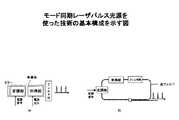
図4は、モード同期レーザパルス光源を使った技術の基本構成を示す図である。The conventional optical pulse generation techniques for this purpose are roughly divided into the following two.
(1) Technology Using Mode-Locked Laser Pulse Light Source (2) Technology Using Directly Modulated Pulse Light Source FIG. 4 is a diagram showing a basic configuration of technology using a mode-locked laser pulse light source.
具体的な例としては、半導体モード同期レーザ(図4(a))、及びファイバモード同期レーザ(図4(b))がある。駆動用RF(Radio Frequency)信号周波数、位相、利得励起用レーザ光のパワー、などのパラメータを制御することにより光信号対雑音比(Optical Signal-to-Noise Ratio)が高くかつRF信号周波数の制限を受けずにデューティ比の高いサブピコ秒の光パルスが生成できる。しかし一方で、モード同期レーザパルス光源は構造上、光パルスの繰り返し周波数を任意にかつ正確に実現できないという課題がある。 Specific examples include a semiconductor mode-locked laser (FIG. 4A) and a fiber mode-locked laser (FIG. 4B). By controlling parameters such as RF (Radio Frequency) signal frequency for driving, phase, and power of laser light for gain pumping, the optical signal-to-noise ratio is high and the RF signal frequency is limited. A sub-picosecond optical pulse with a high duty ratio can be generated without being subjected to this. On the other hand, however, the mode-locked laser pulse light source has a problem that the repetition frequency of the optical pulse cannot be arbitrarily and accurately realized due to its structure.
モード同期レーザでは、光パルスの繰返し周波数f0はレーザの共振器長Lとの関係において、光速をc、共振器媒質の屈折率をn、Nを任意の整数として、In the mode-locked laser, the repetition frequency f0 of the optical pulse is related to the cavity length L of the laser, the speed of light is c, the refractive index of the cavity medium is n, and N is an arbitrary integer.

を満たさなければならない。
そのため、ある正確な繰返し周波数f0、例えば10ギガヘルツ(GHz、ギガ:109)±100Hzの光パルスを生成するためには、Lを正確に作りこまなければならない。Must be met.
Therefore, in order to generate an optical pulse having a certain repetition frequency f0 , for example, 10 gigahertz (GHz, giga: 109 ) ± 100 Hz, L must be accurately created.
例えば、半導体モード同期レーザの場合を考えると、その共振器長は1センチメートル(cm)のオーダーであるがその誤差は1ナノメートル(ナノ:10-9)以下に抑えなければならず製品化における歩留まりを考えるとこの実現は困難である。一方、ファイバモード同期レーザにおいては共振器長が数十メートル単位であるため、Nを調整することで半導体モード同期レーザほど厳しい長さ調節は必要ないが、共振器長が長いために少々の温度変化などにより共振器長の変化が大きくなる。ゆえに、任意に、かつ正確な繰返し周波数で安定に動作させることは難しい。For example, in the case of a semiconductor mode-locked laser, the resonator length is on the order of 1 centimeter (cm), but the error must be suppressed to 1 nanometer (nano: 10-9 ) or less. This is difficult to achieve in view of the yield of On the other hand, the fiber mode-locked laser has a cavity length of several tens of meters, so adjusting the N does not require stricter length adjustment than a semiconductor mode-locked laser. The change in the resonator length increases due to the change. Therefore, it is difficult to operate stably at an arbitrary and accurate repetition frequency.
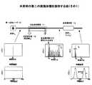
図5は、直接変調型パルス光源を使った技術の基本構成を示す図である。
具体的な例としては、たとえば電界吸収型光変調器(EAM:Electro-absorption modulator)を用いたパルス光源がある。単一波長レーザ光源、EAM、EAM駆動用RF信号源、及び直流電圧源で構成される。この方法ではEAM駆動用RF信号源の制御により任意の繰返し周波数において正確に安定な光パルスを発生可能である。しかし反面、EAMの光透過損失が大きいため、光増幅器を使用して出力パワーを増幅する場合、発生パルス光の光信号対雑音比(OSNR)が大幅に劣化するという問題がある。例えば、EAM自体の光透過損失は7デシベル(dB)程度であるが、光パルスを生成する際には、直流電圧源によりDCの負バイアス電圧をEAMに印加するため、光透過損失が20dB以上となりOSNRの劣化につながる。また、発生する光パルス波形はEAM駆動用RF信号源の波形に依存する為、変調周波数の周期時間と生成する光パルスの時間幅の比(デューティ比)が高い光パルスを生成することは難しいという短所もある。FIG. 5 is a diagram showing a basic configuration of a technique using a directly modulated pulse light source.
As a specific example, for example, there is a pulse light source using an electroabsorption modulator (EAM). It consists of a single wavelength laser light source, EAM, RF signal source for driving EAM, and DC voltage source. In this method, a stable optical pulse can be generated accurately at an arbitrary repetition rate by controlling the RF signal source for EAM driving. However, since the optical transmission loss of EAM is large, when the output power is amplified using an optical amplifier, there is a problem that the optical signal-to-noise ratio (OSNR) of the generated pulse light is greatly deteriorated. For example, the optical transmission loss of EAM itself is about 7 dB (dB), but when generating an optical pulse, a DC negative bias voltage is applied to EAM by a DC voltage source, so the optical transmission loss is 20 dB or more. This leads to OSNR degradation. In addition, since the generated optical pulse waveform depends on the waveform of the RF signal source for EAM driving, it is difficult to generate an optical pulse with a high ratio (duty ratio) between the period time of the modulation frequency and the time width of the generated optical pulse. There are also disadvantages.
上記のような技術の参考文献として、非特許文献1がある。
前述の通り、モード同期レーザパルス光源では高OSNRでサブピコ秒の光パルスを安定に発生させることができるが、一方で正確な共振器長を有するモード同期レーザパルス光源を作製することは歩留まりの面からも困難であり、任意にかつ正確な繰返し周波数での安定動作は難しい。また、直接変調型パルス光源は、制御が簡単で、任意にかつ正確な繰返し周波数での光パルス生成が可能であるが、一方、(1)光強度変調器における光透過損失が大きいため、OSNRの劣化につながる、(2)パルスの幅は変調周波数に制限されるためデューティ比の高い光パルスの生成が難しい、などの短所がある。 As described above, a mode-locked laser pulse light source can stably generate a sub-picosecond optical pulse at a high OSNR. On the other hand, producing a mode-locked laser pulse light source having an accurate resonator length is a factor in yield. Therefore, stable operation at an arbitrary and accurate repetition frequency is difficult. In addition, the direct modulation type pulse light source is easy to control and can generate an optical pulse at an arbitrary and accurate repetition frequency. On the other hand, (1) since the optical transmission loss in the optical intensity modulator is large, the OSNR (2) Since the pulse width is limited to the modulation frequency, it is difficult to generate an optical pulse with a high duty ratio.
本発明の課題は、任意の繰返し周波数において正確にかつ安定に動作し、なお高OSNRを有し、かつRF変調周波数に制限されないピコ秒級の(デューティ比が高い)光パルスの生成方法および装置を提供することである。 An object of the present invention is to provide a method and apparatus for generating a picosecond-class (high duty ratio) optical pulse that operates accurately and stably at an arbitrary repetition frequency, yet has a high OSNR, and is not limited to an RF modulation frequency. Is to provide.
本発明の光パルス発生装置は、単一波長光を出力する光源と、該光源からの光に位相変調をかけ、変調スペクトル成分を生成し、生成される光パルスに含まれる該変調スペクトル成分の各波長の位相を調整することで光パルスを生成する光パルス生成手段とを備えることを特徴とする。 The optical pulse generator of the present invention includes a light source that outputs single-wavelength light, phase-modulates the light from the light source to generate a modulated spectral component, and the modulated spectral component included in the generated optical pulse. And an optical pulse generating means for generating an optical pulse by adjusting the phase of each wavelength.
本発明の光パルス発生方法は、単一波長光を出力する発光ステップと、該発光ステップからの光に位相変調をかけ、変調スペクトル成分を生成し、生成される光パルスに含まれる該変調スペクトル成分の各波長の位相を調整することで光パルスを生成する光パルス生成ステップとを備えることを特徴とする。 The optical pulse generation method of the present invention includes a light emission step for outputting light of a single wavelength, phase modulation of the light from the light emission step to generate a modulation spectrum component, and the modulation spectrum included in the generated optical pulse. An optical pulse generation step of generating an optical pulse by adjusting the phase of each wavelength of the component.
本発明によれば、従来とは異なり、光パルスを生成するのに位相変調を行い、位相変調された結果得られる変調スペクトル成分の各波長の位相をそろえることにより、光パルスを生成する。 According to the present invention, unlike the conventional case, phase modulation is performed to generate an optical pulse, and an optical pulse is generated by aligning the phase of each wavelength of a modulated spectrum component obtained as a result of the phase modulation.
本発明により、制御が簡単で、任意の繰り返し周波数において正確かつ安定に動作し、なおかつ変調信号周波数に制限されず、デューティ比の高いピコ秒級のパルス幅を有する光パルスの生成が可能となる。 According to the present invention, it is possible to generate an optical pulse that is easy to control, operates accurately and stably at an arbitrary repetition frequency, and is not limited to a modulation signal frequency, and has a picosecond pulse width with a high duty ratio. .
本発明の実施形態においては、次の手段により課題を解決する。
まず、単一波長レーザ光源(周波数f)から出射される光に周波数f0の位相変調を加える。この時、w(w=2pf)を単一波長レーザ光源の角周波数、pを変調角周波数(p=2pf0)の角周波数、mは位相変調度、Jνはν次の第一種ベッセル関数とすると、位相変調の結果生成される光の実部は(2)の式で表される。In the embodiment of the present invention, the problem is solved by the following means.
First, phase modulation of frequency f0 is applied to light emitted from a single wavelength laser light source (frequency f). At this time, w (w = 2pf) is an angular frequency of a single wavelength laser light source, p is an angular frequency of a modulation angular frequency (p = 2pf0 ), m is a phase modulation degree, Jν is a ν-order first-order Bessel function. Then, the real part of the light generated as a result of the phase modulation is expressed by the equation (2).
この式においては、変調角周波数p(すなわち周波数間隔f0)毎に新しい波長成分(ν次のモード)が生成されていることが示されている。以降、これを変調スペクトル成分と呼ぶ。ここで、使用する周波数f及び変調周波数f0の具体的数値について述べる。単一波長レーザ光源の周波数fは、光ファイバ通信では波長が1.5マイクロメートル(mm、マイクロ:10-6)帯であるので、周波数では200テラヘルツ(THz、テラ:1012)帯となる。変調周波数f0は、光パルスを光通信の送信用光源として使用する際にはビットレートに相当するため、すなわち10ギガヘルツ(GHz、ギガ:109)、もしくは40GHzとなる。In this equation, it is shown that a new wavelength component (ν-order mode) is generated for each modulation angular frequency p (that is, frequency interval f0 ). Hereinafter, this is referred to as a modulation spectrum component. Here, specific numerical values of the frequency f and the modulation frequency f0 to be used will be described. The frequency f of the single-wavelength laser light source is in the 200 terahertz (THz, 1012 ) band because the wavelength is 1.5 micrometer (mm, micro: 10−6 ) in optical fiber communication. The modulation frequency f0 corresponds to a bit rate when an optical pulse is used as a transmission light source for optical communication, that is, 10 GHz (GHz, Giga: 109 ) or 40 GHz.
図1は、本発明の第1の実施形態を説明する図である。 図1(a)は全体の構成を示すずですある。
単一波長レーザ光源10から出射される光に位相変調器11で位相変調をかけると変調スペクトル成分が生成される。しかしこの位相変調された光の変調スペクトル成分におけるそれぞれの波長成分の位相は揃っておらず、時間波形としては連続光の状態である。光パルスを生成するためには、変調スペクトル成分の波長成分の位相を位相調整器13でそろえる必要がある。FIG. 1 is a diagram for explaining a first embodiment of the present invention. FIG. 1 (a) shows the overall configuration.
When the phase modulator 11 applies phase modulation to the light emitted from the single wavelength laser light source 10, a modulated spectral component is generated. However, the phase of each wavelength component in the modulation spectrum component of the phase-modulated light is not uniform, and the time waveform is a continuous light state. In order to generate an optical pulse, it is necessary to align the phase of the wavelength component of the modulated spectral component with the phase adjuster 13.
位相変調をかける装置(位相変調器11)は、例えばLiNbO3光位相変調器(LN光位相変調器)を使用すればよい。この光変調器はすでに実用化されている。変調信号は例えば汎用の交流信号発振器(シンセサイザ)を使用すればよい。位相変調がかけられた光の変調スペクトル成分の位相関係を調整するには、平面ブレーズド・グレーティングを使用すればよい。位相調整の原理を図1(b)中に示す。二つの平面ブレーズド・グレーティングで構成されており、第一の平面ブレーズド・グレーティング13-1で、光ビームは波長に応じた回折角度に分光される。 次に、分光されたビームを第二の平面ブレーズド・グレーティング13-2で、再び平行光に変換する。一連の操作により、各波長成分の経路に差が生じるために、図中に示すように波面aに対して波面bが波長に応じて時間差が発生し波面がずれる。すなわち、波長に応じた位相調整を与えることが可能になる。For example, a LiNbO3 optical phase modulator (LN optical phase modulator) may be used as an apparatus for applying phase modulation (phase modulator 11). This optical modulator has already been put into practical use. For the modulation signal, for example, a general-purpose AC signal oscillator (synthesizer) may be used. In order to adjust the phase relationship of the modulated spectral component of the light subjected to phase modulation, a plane blazed grating may be used. The principle of phase adjustment is shown in FIG. It is composed of two planar blazed gratings, and the first planar blazed grating 13-1 splits the light beam into a diffraction angle corresponding to the wavelength. Next, the split beam is converted into parallel light again by the second plane blazed grating 13-2. As a result of a series of operations, a difference occurs in the path of each wavelength component, so that as shown in the figure, the wavefront b has a time difference depending on the wavelength, and the wavefront shifts. That is, it becomes possible to give phase adjustment according to the wavelength.
単一波長レーザ光源10には、波長1550nm(周波数193.4145THz)のレーザ光源を使用する。これを光位相変調器11に入射し変調スペクトル成分を生成する。ここでは、変調度5pの正弦波位相変調を施している。変調度5pの位相変調はOptical Fiber Communication Conferenceで報告されているVp=1Vの変調器を、変調信号パワー24dBmの交流信号源12から出力される正弦波信号で駆動すれば実現できる。変調信号のパワーは必要があれば電気信号増幅器を用いれば、十分対応可能な値である。この時、変調信号は周波数10GHzであるとすると、変調スペクトル成分が約30本程度発生する。この変調スペクトル成分の位相を平面ブレーズド・グレーティング13で調節する。これによりパルス幅3ps以下の光パルスが生成される。 As the single wavelength laser light source 10, a laser light source having a wavelength of 1550 nm (frequency: 193.4145 THz) is used. This is incident on the optical phase modulator 11 to generate a modulated spectral component. Here, sinusoidal phase modulation with a modulation degree of 5p is performed. Phase modulation with a modulation degree of 5p can be realized by driving a Vp = 1V modulator reported at the Optical Fiber Communication Conference with a sine wave signal output from the AC signal source 12 with a modulation signal power of 24 dBm. If necessary, the power of the modulation signal can be sufficiently handled by using an electric signal amplifier. At this time, if the modulation signal has a frequency of 10 GHz, about 30 modulation spectrum components are generated. The phase of the modulated spectral component is adjusted by the plane blazed grating 13. As a result, an optical pulse with a pulse width of 3 ps or less is generated.
図2は、本発明の第2の実施形態の構成図である。
この実施形態では、波長選択器14をもちいて、単一波長レーザの波長から、光の位相のずれが少ない周波数帯にシフトすればその出力光は光パルスとなる。波長l0の単一波長レーザ光源10から出力される光に変調周波数f0、変調度5pの位相変調を施す。位相変調により生成される変調スペクトル成分の波長l1(l1(l0)を波長選択器14で選択する。f0=10GHzの場合、半値全幅帯域21GHzの波長を選択すると、パルス幅21psの光パルスを生成できる。この光パルスの時間帯域幅積は0.44であり、この方法によりフーリエ変換限界(Fourier Transform Limited、TL)の光パルスの生成が可能である。この実施形態では、図3に示すように周波数チャープの変化が少ない周波数帯では比較的変調スペクトル成分の各波長成分間における位相のずれが少ないことを利用する。FIG. 2 is a configuration diagram of the second embodiment of the present invention.
In this embodiment, if the wavelength selector 14 is used to shift from the wavelength of the single wavelength laser to a frequency band where the phase shift of the light is small, the output light becomes an optical pulse. The light output from the single-wavelength laser light source 10 having the wavelength l0 is subjected to phase modulation with the modulation frequency f0 and the modulation degree 5p. The wavelength l1 (l1 (l0 ) of the modulated spectral component generated by the phase modulation is selected by the wavelength selector 14. When f0 = 10 GHz, a wavelength of the full width at half maximum band of 21 GHz is selected and the pulse width of 21 ps is selected. An optical pulse can be generated, which has a time bandwidth product of 0.44 and can generate a Fourier Transform Limited (TL) optical pulse, which in this embodiment is shown in FIG. As shown, in the frequency band where the change in the frequency chirp is small, the fact that the phase shift between the wavelength components of the modulation spectrum component is relatively small is utilized.
10 単一波長レーザ光源
11 光位相変調器
12 交流信号源
13 位相調整器
14 波長選択器DESCRIPTION OF SYMBOLS 10 Single wavelength laser light source 11 Optical phase modulator 12 AC signal source 13 Phase adjuster 14 Wavelength selector
Claims (2)
Translated fromJapanese該光源からの光に位相変調をかけ、変調スペクトル成分を生成し、生成される光に含まれる該変調スペクトル成分の各波長の位相を調整することで光パルスを生成する光パルス生成手段と、
を備えすることを特徴とする光パルス発生装置。A light source that outputs single wavelength light;
Optical pulse generation means for generating a light pulse by applying phase modulation to light from the light source, generating a modulated spectral component, and adjusting the phase of each wavelength of the modulated spectral component included in the generated light;
An optical pulse generator characterized by comprising:
該光源からの光に位相変調をかけ、変調スペクトル成分を生成し、生成される光に含まれる該変調スペクトル成分で位相のそろっている波長で該光源とは異なる波長成分を波長選択九器で選択することで光パルスを生成する光パルス生成手段と、
を備えることを特徴とする光パルス発生装置。A light source that outputs single wavelength light;
Phase modulation is performed on the light from the light source to generate a modulated spectral component, and a wavelength component different from the light source at a wavelength that is in phase with the modulated spectral component included in the generated light is selected by a wavelength selection unit. An optical pulse generating means for generating an optical pulse by selecting;
An optical pulse generator characterized by comprising:
Priority Applications (3)
| Application Number | Priority Date | Filing Date | Title |
|---|---|---|---|
| JP2003432922AJP2005192046A (en) | 2003-12-26 | 2003-12-26 | Pulse generator and method |
| US10/827,328US7088491B2 (en) | 2003-12-26 | 2004-04-20 | Pulse generating apparatus and method |
| EP04010084AEP1575194A3 (en) | 2003-12-26 | 2004-04-28 | Pulse generating apparatus and method |
Applications Claiming Priority (1)
| Application Number | Priority Date | Filing Date | Title |
|---|---|---|---|
| JP2003432922AJP2005192046A (en) | 2003-12-26 | 2003-12-26 | Pulse generator and method |
Publications (1)
| Publication Number | Publication Date |
|---|---|
| JP2005192046Atrue JP2005192046A (en) | 2005-07-14 |
Family
ID=34697701
Family Applications (1)
| Application Number | Title | Priority Date | Filing Date |
|---|---|---|---|
| JP2003432922APendingJP2005192046A (en) | 2003-12-26 | 2003-12-26 | Pulse generator and method |
Country Status (3)
| Country | Link |
|---|---|
| US (1) | US7088491B2 (en) |
| EP (1) | EP1575194A3 (en) |
| JP (1) | JP2005192046A (en) |
Families Citing this family (3)
| Publication number | Priority date | Publication date | Assignee | Title |
|---|---|---|---|---|
| GB2434483A (en) | 2006-01-20 | 2007-07-25 | Fianium Ltd | High-Power Short Optical Pulse Source |
| GB0800936D0 (en) | 2008-01-19 | 2008-02-27 | Fianium Ltd | A source of optical supercontinuum generation having a selectable pulse repetition frequency |
| JP2009238285A (en)* | 2008-03-26 | 2009-10-15 | Sony Corp | Optical recording method and optical recording apparatus |
Family Cites Families (17)
| Publication number | Priority date | Publication date | Assignee | Title |
|---|---|---|---|---|
| JPH0595152A (en) | 1991-10-01 | 1993-04-16 | Nippon Telegr & Teleph Corp <Ntt> | Semiconductor short optical pulse generator and generating method for short optical pulse |
| IT1263613B (en) | 1993-02-19 | 1996-08-27 | Pirelli Cavi Spa | FIBER OPTIC LASER GENERATOR WITH ACTIVE MODAL CHAIN |
| US5432631A (en) | 1994-04-06 | 1995-07-11 | At&T Corp. | Dual-wavelength source of high-repetition rate, transform-limited optical pulses |
| US6072715A (en)* | 1994-07-22 | 2000-06-06 | Texas Instruments Incorporated | Memory circuit and method of construction |
| US5473458A (en)* | 1994-12-27 | 1995-12-05 | At&T Corp. | Soliton data transmission using non-soliton transmitter |
| JPH10206807A (en)* | 1997-01-16 | 1998-08-07 | Oki Electric Ind Co Ltd | Optical pulse generator |
| US5963567A (en)* | 1997-02-13 | 1999-10-05 | Lucent Technologies, Inc. | Multi-wavelength laser source |
| US6072615A (en) | 1997-06-13 | 2000-06-06 | Lucent Technologies Inc. | Phase modulator-based generation of high-quality high bit rate return-to-zero optical data streams |
| US6831774B2 (en)* | 2000-07-07 | 2004-12-14 | Nippon Telegraph And Telephone Corporation | Multi-wavelength generating method and apparatus based on flattening of optical spectrum |
| GB2365140B (en) | 2000-07-22 | 2002-08-07 | Marconi Caswell Ltd | Optical pulse train generator |
| US6643046B2 (en) | 2001-09-26 | 2003-11-04 | Kabushiki Kaisha Toshiba | Apparatus and method for optical modulation |
| US7266307B2 (en)* | 2002-02-01 | 2007-09-04 | Isaac Shpantzer | Method and apparatus for pulse generation and adaptive pulse generation for optical communications |
| US7366425B2 (en)* | 2002-03-15 | 2008-04-29 | Mintera Corporation | Methods and apparatus for spectrally efficient optical modulation |
| US6717708B2 (en)* | 2002-04-05 | 2004-04-06 | Bookham Technology, Plc | Re-circulating optical pulse generator |
| JP3975810B2 (en)* | 2002-04-05 | 2007-09-12 | 株式会社日立製作所 | Optical single sideband transmitter |
| US6760142B2 (en)* | 2002-05-13 | 2004-07-06 | Lucent Technologies Inc. | Delay interferometer optical pulse generator |
| US7027669B2 (en)* | 2003-08-15 | 2006-04-11 | Lucent Technologies Inc. | Methods and apparatus for optical pulse generator with progressive phase shift |
- 2003
- 2003-12-26JPJP2003432922Apatent/JP2005192046A/enactivePending
- 2004
- 2004-04-20USUS10/827,328patent/US7088491B2/ennot_activeExpired - Fee Related
- 2004-04-28EPEP04010084Apatent/EP1575194A3/ennot_activeWithdrawn
Also Published As
| Publication number | Publication date |
|---|---|
| EP1575194A3 (en) | 2005-12-21 |
| US7088491B2 (en) | 2006-08-08 |
| EP1575194A2 (en) | 2005-09-14 |
| US20050141073A1 (en) | 2005-06-30 |
Similar Documents
| Publication | Publication Date | Title |
|---|---|---|
| US8260149B2 (en) | Carrier-suppressed optical pulse train generating device | |
| JP4047224B2 (en) | Reference high frequency signal generation method and reference high frequency signal generation apparatus | |
| US8494378B2 (en) | Synchronous optical signal generating device and synchronous optical signal generating method | |
| JP5668265B2 (en) | Optical frequency comb generating apparatus and optical frequency comb generating method | |
| JP4402071B2 (en) | High density multi-wavelength light source | |
| CN104333419A (en) | Tunable multi-wavelength light source and modulation method thereof | |
| Gao et al. | Experimental demonstration of arbitrary waveform generation by a 4-bit photonic digital-to-analog converter | |
| CN110967892A (en) | Optical frequency comb generation device and method based on MZM-EAM cascade and pulse signal | |
| CN106532430A (en) | Frequency and wavelength dual-tunable frequency modulation continuous wave optical carrier signal generation system | |
| JP5665038B2 (en) | Broadband optical comb generator | |
| US20050190432A1 (en) | Optical device for optical communication | |
| JP2008288390A (en) | Tunable optical frequency stabilized light source | |
| JP2019039972A (en) | Signal generator and signal generation method | |
| WO2021079710A1 (en) | Arbitrary waveform generation device and arbitrary waveform generation method | |
| Ozharar et al. | Demonstration of endless phase modulation for arbitrary waveform generation | |
| US20050047453A1 (en) | Multi-wavelength light source apparatus | |
| JP2005192046A (en) | Pulse generator and method | |
| JP3573334B2 (en) | Light generation method and light source | |
| JP4963462B2 (en) | Multi-wavelength light source device | |
| CN103780307B (en) | A kind of system and method that produces Optical Sampling pulse train | |
| JPH07281217A (en) | Two-wavelength source of optical pulse, whose repeating speed is quick and transformation is limited | |
| JP4468877B2 (en) | Multi-wavelength light source | |
| JP2004294543A (en) | Periodic multi-wavelength light generator | |
| JP2006208656A (en) | Optical frequency comb generating method, optical frequency comb generator, and high density wavelength multiplexing transmission system | |
| JP4621083B2 (en) | Multi-carrier light source |
Legal Events
| Date | Code | Title | Description |
|---|---|---|---|
| A621 | Written request for application examination | Free format text:JAPANESE INTERMEDIATE CODE: A621 Effective date:20060721 | |
| A977 | Report on retrieval | Free format text:JAPANESE INTERMEDIATE CODE: A971007 Effective date:20071129 | |
| A131 | Notification of reasons for refusal | Free format text:JAPANESE INTERMEDIATE CODE: A131 Effective date:20080318 | |
| A521 | Request for written amendment filed | Free format text:JAPANESE INTERMEDIATE CODE: A523 Effective date:20080519 | |
| A02 | Decision of refusal | Free format text:JAPANESE INTERMEDIATE CODE: A02 Effective date:20080617 | |
| A521 | Request for written amendment filed | Free format text:JAPANESE INTERMEDIATE CODE: A523 Effective date:20080818 | |
| A911 | Transfer to examiner for re-examination before appeal (zenchi) | Free format text:JAPANESE INTERMEDIATE CODE: A911 Effective date:20080828 | |
| A912 | Re-examination (zenchi) completed and case transferred to appeal board | Free format text:JAPANESE INTERMEDIATE CODE: A912 Effective date:20080926 |