JP2005191819A - Mobile communication system and mobile terminal wearing device - Google Patents
Mobile communication system and mobile terminal wearing deviceDownload PDFInfo
- Publication number
- JP2005191819A JP2005191819AJP2003429363AJP2003429363AJP2005191819AJP 2005191819 AJP2005191819 AJP 2005191819AJP 2003429363 AJP2003429363 AJP 2003429363AJP 2003429363 AJP2003429363 AJP 2003429363AJP 2005191819 AJP2005191819 AJP 2005191819A
- Authority
- JP
- Japan
- Prior art keywords
- information
- function
- mobile
- portable terminal
- mobile terminal
- Prior art date
- Legal status (The legal status is an assumption and is not a legal conclusion. Google has not performed a legal analysis and makes no representation as to the accuracy of the status listed.)
- Pending
Links
- 238000010295mobile communicationMethods0.000titleclaimsdescription33
- 238000004891communicationMethods0.000claimsabstractdescription158
- 230000010365information processingEffects0.000claimsdescription30
- 230000005540biological transmissionEffects0.000claimsdescription17
- 238000001514detection methodMethods0.000claimsdescription3
- 238000006243chemical reactionMethods0.000abstractdescription130
- 230000006870functionEffects0.000description494
- 238000000034methodMethods0.000description64
- 230000008569processEffects0.000description62
- 238000012545processingMethods0.000description38
- 238000004364calculation methodMethods0.000description14
- 238000012790confirmationMethods0.000description13
- 238000010586diagramMethods0.000description13
- 238000012905input functionMethods0.000description11
- 230000008859changeEffects0.000description9
- 230000007246mechanismEffects0.000description7
- 230000003287optical effectEffects0.000description7
- 230000004913activationEffects0.000description6
- 230000004048modificationEffects0.000description5
- 238000012986modificationMethods0.000description5
- 230000001133accelerationEffects0.000description4
- 230000002159abnormal effectEffects0.000description3
- 230000005494condensationEffects0.000description3
- 238000009833condensationMethods0.000description3
- 238000009434installationMethods0.000description3
- 238000012423maintenanceMethods0.000description3
- 230000004397blinkingEffects0.000description2
- 230000003247decreasing effectEffects0.000description2
- 230000002950deficientEffects0.000description2
- 238000012217deletionMethods0.000description2
- 230000037430deletionEffects0.000description2
- 239000000428dustSubstances0.000description2
- 230000000694effectsEffects0.000description2
- 230000008439repair processEffects0.000description2
- 230000002441reversible effectEffects0.000description2
- 238000007792additionMethods0.000description1
- 230000003321amplificationEffects0.000description1
- 238000004458analytical methodMethods0.000description1
- 230000002238attenuated effectEffects0.000description1
- 230000001413cellular effectEffects0.000description1
- 230000000295complement effectEffects0.000description1
- 238000001816coolingMethods0.000description1
- 230000007423decreaseEffects0.000description1
- 230000001419dependent effectEffects0.000description1
- 238000003745diagnosisMethods0.000description1
- 230000004069differentiationEffects0.000description1
- 239000013013elastic materialSubstances0.000description1
- 238000005401electroluminescenceMethods0.000description1
- 230000005484gravityEffects0.000description1
- 230000010354integrationEffects0.000description1
- 239000007788liquidSubstances0.000description1
- 239000004973liquid crystal related substanceSubstances0.000description1
- 230000007257malfunctionEffects0.000description1
- 238000004519manufacturing processMethods0.000description1
- 239000000463materialSubstances0.000description1
- 239000011159matrix materialSubstances0.000description1
- 229910044991metal oxideInorganic materials0.000description1
- 150000004706metal oxidesChemical class0.000description1
- 238000012544monitoring processMethods0.000description1
- 238000003199nucleic acid amplification methodMethods0.000description1
- 239000013307optical fiberSubstances0.000description1
- 230000001172regenerating effectEffects0.000description1
- 230000004044responseEffects0.000description1
- 210000001525retinaAnatomy0.000description1
- 238000007789sealingMethods0.000description1
- 239000004065semiconductorSubstances0.000description1
- 239000007787solidSubstances0.000description1
- 238000012546transferMethods0.000description1
- 230000007704transitionEffects0.000description1
- 239000012780transparent materialSubstances0.000description1
- XLYOFNOQVPJJNP-UHFFFAOYSA-NwaterSubstancesOXLYOFNOQVPJJNP-UHFFFAOYSA-N0.000description1
- 238000004804windingMethods0.000description1
Images


Landscapes
- Data Exchanges In Wide-Area Networks (AREA)
- Telephone Function (AREA)
Abstract
Description
Translated fromJapanese本発明は、自動車等の移動体で情報の処理を行う移動体通信システムおよび携帯端末装着装置に関する。詳しくは、携帯端末を移動体に着脱自在に装着でき、かつ、移動体と携帯端末の間で情報を送受するゲートウエイ装置を備えることで、汎用の携帯端末で移動体の情報を処理できるようにしたものである。 The present invention relates to a mobile communication system and a mobile terminal mounting apparatus that process information on a mobile body such as an automobile. Specifically, the mobile terminal can be detachably attached to the mobile body, and the mobile device can be processed with a general-purpose mobile terminal by including a gateway device that transmits and receives information between the mobile body and the mobile terminal. It is a thing.
自動車等の移動体ではナビゲーションシステム等の情報端末が搭載されている(例えば、特許文献1参照)。また、オーディオ機器やナビゲーションシステム等の複数の情報端末を車内ネットワークを介して接続できるようにした通信システムが提案されている。更に、エンジン制御等の制御系のシステムを車内ネットワークで接続し、故障診断を行えるようにしたシステムも開示されている(例えば、特許文献2参照)。 A mobile body such as an automobile is equipped with an information terminal such as a navigation system (see, for example, Patent Document 1). There has also been proposed a communication system in which a plurality of information terminals such as audio devices and navigation systems can be connected via an in-vehicle network. Furthermore, a system in which a control system such as engine control is connected via an in-vehicle network so that failure diagnosis can be performed is also disclosed (see, for example, Patent Document 2).
このような移動体の通信システムでは、高速化、通信の安全性から様々なプロトコルが利用されている。このため、移動体に接続される情報端末は専用のものが多い。 In such a mobile communication system, various protocols are used for speeding up and safety of communication. For this reason, there are many dedicated information terminals connected to the mobile body.
従来より移動体の通信システムで利用されるプロトコルは、移動体の利用者が所有する汎用の携帯端末で利用するプロトコルとは異なる。よって、利用者が所有する携帯端末を移動体に接続して使用することはできなかった。 Conventionally, a protocol used in a mobile communication system is different from a protocol used in a general-purpose portable terminal owned by a mobile user. Therefore, the mobile terminal owned by the user cannot be used by connecting to the mobile object.
このため、移動体に通信システムが準備されている場合、この通信システムを利用するには専用の情報端末を用意する必要があったが、移動体用の情報端末は高価なものが多く、システムの構築にコストがかかる。 For this reason, when a communication system is prepared for a mobile body, it is necessary to prepare a dedicated information terminal in order to use this communication system. However, many information terminals for mobile bodies are expensive, and the system Cost to build.
また、移動体に接続される情報端末は、移動体に対する着脱を考慮していないものが多く、情報端末をケーブル等を用いて移動体に接続する構成となっている。このため一度情報端末を移動体に取り付けると、情報端末を移動体から取り外すことは容易に行えない。 In addition, many information terminals connected to a mobile body do not consider attachment / detachment to / from the mobile body, and the information terminal is connected to the mobile body using a cable or the like. For this reason, once an information terminal is attached to a mobile body, it is not easy to remove the information terminal from the mobile body.
このため、移動体を使用していないときに情報端末を携帯して使用することができない。また、情報端末を移動体から取り外したとしても、使用しないケーブルの処理等が考慮されておらず、ケーブルの収納等に手間がかかり現実的ではない。 For this reason, when the mobile body is not used, the information terminal cannot be carried and used. Moreover, even if the information terminal is removed from the mobile object, the processing of cables that are not used is not taken into consideration, and it takes time to store the cables and is not realistic.
更に、携帯電話等を自動車のダッシュボード等に固定しておくアタッチメントも提案されているが、これは携帯端末を単に固定するだけの機能しか持たず、携帯端末の持つ機能を有効に活用することはできない。 In addition, an attachment to fix a mobile phone etc. to the dashboard of a car has been proposed, but this has only a function of fixing the mobile terminal, and effectively uses the function of the mobile terminal. I can't.
本発明は、このような課題を解決するためになされたもので、汎用の携帯端末を利用して移動体との間で情報の処理を行えるようにした移動体通信システムおよび携帯端末装着装置を提供することを目的とする。 The present invention has been made to solve such a problem, and provides a mobile communication system and a mobile terminal mounting apparatus that can perform information processing with a mobile body using a general-purpose mobile terminal. The purpose is to provide.
PDA(personal digital assistants)等の情報端末または携帯可能なゲーム機等の携帯端末は、外部機器と接続できるようにするため、汎用性のある通信規格の接続機能をほぼ全てが有している。このため、この接続機能を利用して移動体と携帯端末とを接続し、移動体の情報を情報端末へ、または情報端末の情報を移動体へと、情報の送受ができるようにすれば良い。 An information terminal such as a PDA (personal digital assistants) or a portable terminal such as a portable game machine has almost all connection functions of a versatile communication standard so that it can be connected to an external device. For this reason, it is only necessary to connect the mobile body and the portable terminal by using this connection function so that the information of the mobile body can be transmitted to and received from the information terminal or the information of the information terminal to the mobile body. .
すなわち、本発明に係る移動体通信システムは、情報処理手段を有する移動体にゲートウエイ装置を備え、このゲートウエイ装置は、外部接続手段および情報処理手段を有する携帯端末の外部接続手段と着脱自在に接続される接続手段と、移動体の情報処理手段と携帯端末の情報処理手段との間で情報を変換して送受を行う通信制御手段とを備えたものである。 That is, the mobile communication system according to the present invention includes a gateway device in a mobile body having information processing means, and the gateway device is detachably connected to the external connection means of the mobile terminal having the external connection means and the information processing means. And a communication control means for converting information between the information processing means of the mobile body and the information processing means of the portable terminal to transmit / receive information.
また、携帯端末を移動体内に置いておくためだけに使っていたアタッチメント等の装着装置を利用して、上述した移動体通信システムを構成することができる。 In addition, the above-described mobile communication system can be configured using an attachment device such as an attachment that has been used only for placing the mobile terminal in the mobile body.
すなわち、本発明に係る携帯端末装着装置は、携帯端末が着脱自在に装着される装着手段と、移動体の情報処理手段と接続されるゲートウエイ装置を備え、このゲートウエイ装置は、携帯端末の外部接続手段と着脱自在に接続される接続手段と、移動体の情報処理手段と携帯端末の情報処理手段との間で情報を変換して送受を行う通信制御手段とを備えたものである。 That is, the mobile terminal mounting apparatus according to the present invention includes a mounting means for detachably mounting the mobile terminal, and a gateway apparatus connected to the information processing means of the mobile body. The gateway apparatus is connected to the mobile terminal externally. Connecting means detachably connected to the means, and communication control means for converting information between the information processing means of the mobile body and the information processing means of the portable terminal to send and receive information.
本発明に係る移動体通信システムによると、ゲートウエイ装置は接続手段で携帯端末の外部接続手段と接続し、移動体と携帯端末を通信可能な状態に接続する。ゲートウエイ装置は、移動体の情報処理手段から取得した情報を通信制御手段で変換し、携帯端末の情報処理手段に送る。また、携帯端末の情報処理手段から取得した情報を変換して、移動体の情報処理手段に送る。 According to the mobile communication system of the present invention, the gateway device is connected to the external connection means of the mobile terminal by the connection means, and connects the mobile body and the mobile terminal in a communicable state. The gateway device converts the information acquired from the information processing means of the moving body by the communication control means and sends it to the information processing means of the portable terminal. Also, the information acquired from the information processing means of the portable terminal is converted and sent to the information processing means of the mobile body.
本発明に係る携帯端末装着装置によると、携帯端末を装着手段で装着すると、ゲートウエイ装置は接続手段で携帯端末の外部接続手段と接続し、移動体と携帯端末を通信可能な状態に接続する。ゲートウエイ装置は、移動体の情報処理手段から取得した情報を通信制御手段で変換し、携帯端末の情報処理手段に送る。また、携帯端末の情報処理手段から取得した情報を変換して、移動体の情報処理手段に送る。 According to the mobile terminal mounting apparatus of the present invention, when the mobile terminal is mounted by the mounting means, the gateway device is connected to the external connection means of the mobile terminal by the connecting means, and connects the mobile body and the mobile terminal in a communicable state. The gateway device converts the information acquired from the information processing means of the moving body by the communication control means and sends it to the information processing means of the portable terminal. Also, the information acquired from the information processing means of the portable terminal is converted and sent to the information processing means of the mobile body.
本発明に係る移動体通信システムでは、移動体側の情報をゲートウエイ装置で変換して携帯端末に送り、また、携帯端末側の情報をゲートウエイ装置で変換して移動体に送ることができる。これにより、利用者が所有する汎用の携帯端末に移動体の情報を発信することができる。したがって、移動体の情報を利用するシステムを低コストで実現することができる。 In the mobile communication system according to the present invention, information on the mobile body side can be converted by the gateway device and sent to the mobile terminal, and information on the mobile terminal side can be converted by the gateway device and sent to the mobile body. Thereby, the mobile body information can be transmitted to a general-purpose portable terminal owned by the user. Therefore, it is possible to realize a system that uses information on a mobile object at a low cost.
本発明に係る携帯端末装着装置では、上述したゲートウエイ装置に携帯端末を着脱自在に装着する装着手段を備えたので、移動体の任意の位置に携帯端末を固定することができる。これにより、移動体の使用時には、携帯端末を移動体の情報を発信する端末として利用することができる。また、移動体を降りた後は、携帯端末を移動体から取り外して通常の電話機やゲーム機として使うことができる。したがって、携帯端末を有効活用できるシステムを安価に実現できる。 In the portable terminal mounting device according to the present invention, the portable terminal can be fixed at an arbitrary position of the moving body because the mounting device for detachably mounting the portable terminal on the gateway device described above is provided. Thereby, when using a mobile body, a portable terminal can be utilized as a terminal which transmits the information of a mobile body. In addition, after getting off the moving body, the mobile terminal can be detached from the moving body and used as a normal telephone or game machine. Therefore, a system that can effectively use the mobile terminal can be realized at low cost.
以下、図面を参照して本発明の移動体通信システムおよび携帯端末装着装置の実施の形態について説明する。図1は本実施の形態の移動体通信システムの構成例を示す機能ブロック図である。 Embodiments of a mobile communication system and a mobile terminal mounting apparatus according to the present invention will be described below with reference to the drawings. FIG. 1 is a functional block diagram showing a configuration example of a mobile communication system according to the present embodiment.
(1)システム概要
本実施の形態の移動体通信システム1は、自動車やオートバイ、自転車等の移動体2にゲートウエイ装置として機能するアタッチメントシステム3を備え、移動体2の利用者が所有する汎用の携帯端末4を移動体2に着脱自在に装着し、移動体2と携帯端末4との間で情報の送受を行えるようにしたものである。(1) System Overview A
移動体2は移動体制御機能5と移動体センサ機能6を備え、各種センサでの検出結果に基づき、移動体制御機能5が移動体2の制御を行う。自動車等の移動体2では、CAN(controller area network)等の車内ネットワークで制御系の情報の送受が行われる。 The moving
これに対して、利用者が所有している携帯端末4は、外部機器との通信機能は備えるが、一般的に車内ネットワークの通信プロトコルには対応していない。そこで、通信プロトコルの変換機能等を備えたアタッチメントシステム3を用いる。 On the other hand, the
アタッチメントシステム3は携帯端末装着装置であって、携帯端末4を着脱自在に固定する装着手段に加えて、移動体2と接続するため第1の接続機能7と第1の通信機能8を備える。また、携帯端末4と接続するため第2の接続機能9と第2の通信機能10を備える。そして、移動体2と携帯端末4との間で情報の送受や処理を行うため情報変換機能11を備える。更に、アタッチメントシステム3で情報を出力するため音発生機能12を備える。 The
携帯端末4はパーソナルコンピュータ、PDA、携帯可能なゲーム機、タブレット、ウェアラブル端末、携帯電話、腕時計型情報端末等の携帯できる機器である。携帯端末4は外部機器との通信を行うため通信機能13を備える。また、情報の送受や処理を行うため情報変換機能14を備える。更に、情報の入出力を行うためインタフェース機能15と情報表示機能16aと情報入力機能16bと音発生機能17を備える。なお、移動体2および携帯端末4においては本実施の形態で使用する機能のみを図示している。 The
(2)移動体の構成
まず、移動体2の構成について説明する。移動体制御機能5は移動体2の情報処理手段であって、CPU(central processing unit)等の演算処理装置で実現され、移動体2の各種制御を行う。移動体制御機能5には移動体センサ機能6を構成する各種センサが接続され、移動体2の状態を示す情報等の各種情報を取得する。(2) Configuration of Moving Body First, the configuration of the moving
移動体センサ機能6は移動体2の検出手段であって、移動体2の速度等の状態の変化を機械的あるいは電気的な変化として検出し、変化に応じた電圧や電流に変換して出力する機能であり、各種センサとアンプドライバ等で実現される。移動体センサ機能6は移動体2の状態の変化に応じた電圧や電流、必要に応じてこれら電圧値や電流値を更に加工したデータを移動体制御機能5あるいはアタッチメントシステム3に出力する。 The moving
(3)アタッチメントシステムの構成
次に、アタッチメントシステム3の構成について説明する。第1の接続機能7はコネクタ、光電変換機能あるいは電波電圧変換機能等と、送受される通信媒体である通信線で実現され、移動体制御機能5および移動体センサ機能6と、アタッチメントシステム3の第1の通信機能8を接続し、アタッチメントシステム3と移動体2との間で情報の送受を行う。(3) Configuration of Attachment System Next, the configuration of the
この第1の接続機能7によるアタッチメントシステム3と移動体2の接続は、着脱を考慮して一度接続した後でも容易に取り外せる構成としても良いし、取り外しを考慮しない構成でも良い。 The connection between the
第1の通信機能8は移動体2が使用する通信プロトコルで情報の送受を行う機能であり、所定のプロトコルに情報を変換するモジュールとCPUを1チップ化したハードウエア、あるいは情報変換機能11に内包されるソフトウエアで実現される。第1の通信機能8は第1の接続機能7でアタッチメントシステム3に接続される移動体制御機能5および移動体センサ機能6と、アタッチメントシステム3の情報変換機能11との間で通信プロトコルの変換や情報の送受を行う。 The
第2の接続機能9はコネクタ、光電変換機能あるいは電波電圧変換機能等と、送受される通信媒体である通信線で実現され、アタッチメントシステム3と携帯端末4、更にはアタッチメントシステム3と外部装置18や外部記憶機能19を接続して情報の送受を行う。アタッチメントシステム3と携帯端末4を接続することで、第2の接続機能9は携帯端末4の通信機能13および音発生機能17と接続される。 The
この第2の接続機能9によるアタッチメントシステム3と携帯端末4との接続は、後述するように着脱が容易な構成とする。なお、アタッチメントシステム3と携帯端末4との間の通信線は、有線で伝達されるもので実現しても、無線で伝達されるもので実現しても良い。 The connection between the
第2の通信機能10は携帯端末4が使用する通信プロトコルで情報の送受を行う機能であり、情報変換モジュールやソフトウエアで実現され、情報変換機能11と第2の接続機能9を接続して、情報変換機能11からの情報を携帯端末4が使用する通信プロトコルに合致するデータや、電圧と経過時間で表される電圧波形や、電流と経過時間で表される電流値波形に変換して第2の接続機能9に出力する。また、第2の通信機能10は第2の接続機能9から受けた所定の通信規格のデータあるいは電圧波形等を変換して必要な情報を取り出し、アタッチメントシステム3の情報変換機能11へ送る。 The
情報変換機能11はアタッチメントシステム3の情報処理を行う機能であり、CPU等とソフトウエアで実現される。情報変換機能11は第1の通信機能8と第2の通信機能10と音発生機能12に接続され、移動体2や携帯端末4から取得した情報を処理し、第1の通信機能8と第2の通信機能10と音発生機能12に命令や情報を出力する。 The
以上説明した第1の通信機能8、第2の通信機能10および情報変換機能11はアタッチメントシステム3の通信制御手段を構成する。また、第2の接続機能9はアタッチメントシステム3の接続手段を構成する。 The
音発生機能12はアタッチメントシステム3の音発生手段である。音発生機能12は、電圧を空気の振動に変換する機能の他、電圧で示される音情報をイコライジングする機能や、電圧を増幅するアンプ機能や外部との入出力機能や録音機能、音の基となる波形を作成、加工、増幅する機能のうち1つ以上を持つ。よって、スピーカシステムとアンプとイコライザと入出力端子等で実現される。 The
これにより、音発生機能12はスピーカシステムにより電圧を空気振動に変換し、音として出力する。また、アンプにより空気振動の大きさを変更して音量を調整する。更に、イコライザにより特定の周波数の振動のみを増減させて音質を調整する。また、電圧で表される音情報を入出力端子により入出力する。音発生機能12は第1の接続機能7、第2の接続機能9および情報変換機能11に接続され、音データを移動体2の利用者や移動体2の整備者に伝える。 Thereby, the
更に、図示しないがアタッチメントシステム3は携帯端末4を着脱自在に装着できる装着手段を備える。例えば、携帯端末4の形状に合わせて携帯端末4が嵌る構造を備える。なお移動体2は振動が発生するので、振動による落下を防止する構造が必要となる。あるいは様々な形状の携帯端末4に対応するためベルト等で固定する構造を備える。 Furthermore, although not shown, the
(4)携帯端末の構成
次に携帯端末4の構成について説明する。携帯端末4の通信機能13は外部接続手段であって、通信プロトコルを変換するモジュールとCPU等を1チップ化したハードウエア、あるいは情報変換機能14に内包されるソフトウエアで実現される。通信機能13は第2の接続機能9と情報変換機能14とに接続され、第2の接続機能9と情報変換機能14との間で通信ができるように通信プロトコルを変換し、アタッチメントシステム3と携帯端末4の間で情報の送受を行う。(4) Configuration of Mobile Terminal Next, the configuration of the
情報変換機能14は携帯端末4の情報処理手段であって、CPU等とソフトウエアで実現される。情報変換機能14は通信機能13とインタフェース機能15に接続され、通信機能13から送られてくる情報をインタフェース機能15に指示として情報を出す。また、情報変換機能14はインタフェース機能15からの依頼を受けた場合は、依頼内容に応じた処理を行い、処理が行えない場合は、処理が正常に行えない旨をインタフェース機能15に返す処理を実行する。 The
インタフェース機能15は電圧で表される画像情報を出力するハードウエアとソフトウエア、電圧で表される入力情報を出力するハードウエアとソフトウエア、電圧で表される音情報を出力するハードウエアとソフトウエア等で実現され、情報変換機能14と情報表示機能16aと情報入力機能16bおよび音発生機能17とに接続される。 The interface function 15 includes hardware and software for outputting image information represented by voltage, hardware and software for outputting input information represented by voltage, and hardware and software for outputting sound information represented by voltage. And is connected to the
インタフェース機能15は情報変換機能14から送られてくる情報を基に表示や音を発生させる情報を生成し、情報表示機能16aあるいは音発生機能17に送る。また、情報入力機能16bから入力された情報を情報変換機能14に送る。 The interface function 15 generates information for generating a display and sound based on the information sent from the
情報表示機能16aは表示手段であって、LED(発光ダイオード)やマトリクス状に配置された光源を使用したディスプレイ機能であり、LEDやLCD(液晶ディスプレイ)や有機や無機のEL(エレクトロ・ルミネッセンス)ディスプレイ等で実現される。 The information display function 16a is a display means, which is a display function using LEDs (light emitting diodes) or light sources arranged in a matrix, and is an LED, LCD (liquid crystal display), organic or inorganic EL (electroluminescence). Realized by a display or the like.
情報表示機能16aはインタフェース機能15に接続され、インタフェース機能15から送られてくる電圧で表される画像情報を光に変換して表示し、使用者が視認できるようにする。 The information display function 16a is connected to the interface function 15, and converts the image information represented by the voltage sent from the interface function 15 into light and displays it so that the user can visually recognize it.
情報入力機能16bは情報入力手段であって、キーボードやタッチパネル等で実現される。情報入力機能16bはインタフェース機能15に接続され、利用者により入力された情報を電圧等で表される入力情報に変換して情報変換機能14に送る。 The information input function 16b is information input means and is realized by a keyboard, a touch panel, or the like. The information input function 16 b is connected to the interface function 15, converts information input by the user into input information represented by voltage or the like, and sends the input information to the
携帯端末4の音発生機能17は音発生手段であって、アタッチメントシステム3の音発生機能12と同等の機能を具備することで構成され、空気を振動させるスピーカシステムとアンプやイコライザと入出力端子等で実現される。 The
音発生機能17はインタフェース機能15と第2の接続機能9に接続され、電圧を空気振動に変換し、音として出力する。また、空気振動の大きさを変更して音量を調整する。更に、特定の周波数の振動のみを増減させて音質を調整する。また、電圧で表される音情報を入出力する。 The
(5)アタッチメントシステムに接続される他の機器の構成
次に、アタッチメントシステム3に接続される他の機器の構成について説明する。外部装置18はパーソナルコンピュータやPDAやウェアラブル端末や車載機等のオプション機器であり、第2の接続機能9とデータ通信線18aで接続され、実行する機能に応じた情報をデータ通信線18aで入出力する。(5) Configuration of Other Device Connected to Attachment System Next, the configuration of another device connected to the
外部記憶機能19は記憶手段であって、例えば不揮発性メモリとコネクタとそれを保護する筐体等で実現され、第2の接続機能9に接続される。このため、アタッチメントシステム3は第2の接続機能9に記憶部接続手段として接続端子や接続ポートを備える。 The
外部記憶機能19は移動体2のセットアップ情報や、ログ情報や、速度や航続距離といった移動体2に関する情報、更には移動体2の利用者の特定の情報等を記憶する。なお、外部記憶機能19は、携帯端末4に記憶機能が備えられている場合は、この既存の記憶機能を利用してもよく、また、第2の接続機能9でアタッチメントシステム3に接続される携帯端末4とは別方式の記憶メディアを利用しても良い。 The
(6)移動体通信システムの各機能の具体例
図2は移動体通信システム1の各機能の具体例を示すブロック図であり、以下に図1で説明したアタッチメントシステム3と携帯端末4の各機能の詳細を説明する。(6) Specific Example of Each Function of Mobile Communication System FIG. 2 is a block diagram showing a specific example of each function of the
(6−1)接続機能の構成
図1で説明したアタッチメントシステム3の第1の接続機能7と第2の接続機能9は、図2(a)に示すようにコネクト部20と通信線21で実現される。コネクト部20は情報の送受信手段で、通信線21は送受される通信媒体である。図3は接続機能の具体例を示す説明図で、以下に第1の接続機能7および第2の接続機能9の具体的構成を説明する。(6-1) Configuration of Connection Function The
図3(a)はコネクト部としてアンテナ20aを備え、通信線として電波21aを用いる形態である。この図3(a)に示す形態を第1の接続機能7に適用する場合は、アンテナ20aを図1に示す移動体2とアタッチメントシステム3に備える。また、第2の接続機能9に適用する場合は、アンテナ20aをアタッチメントシステム3と携帯端末4に備える。 FIG. 3A shows a form in which an antenna 20a is provided as a connecting portion and a radio wave 21a is used as a communication line. When the configuration shown in FIG. 3A is applied to the
図3(b)はコネクト部としてコイル20bを備え、通信線として電波21bを用いる形態である。この図3(b)に示す形態を第1の接続機能7に適用する場合は、コイル20bを図1に示す移動体2とアタッチメントシステム3に備える。また、第2の接続機能9に適用する場合は、コイル20bをアタッチメントシステム3と携帯端末4に備える。 FIG. 3B shows a form in which a
図3(c)はコネクト部として発光ダイオードやフォトダイオード等を備えた光送受信機20cを備え、通信線として光あるいは赤外線21cを用いる形態である。この図3(c)に示す形態を第1の接続機能7に適用する場合は、光送受信機20cを図1に示す移動体2とアタッチメントシステム3に備える。また、第2の接続機能9に適用する場合は、光送受信機20cをアタッチメントシステム3と携帯端末4に備える。 FIG. 3C shows a form in which an
図3(d)はコネクト部としてスピーカ・マイク20dを備え、通信線として音波あるいは超音波21dを用いる形態である。この図3(d)に示す形態を第1の接続機能7に適用する場合は、スピーカ・マイク20dを図1に示す移動体2とアタッチメントシステム3に備える。また、第2の接続機能9に適用する場合は、スピーカ・マイク20dをアタッチメントシステム3と携帯端末4に備える。 FIG. 3D shows a form in which a speaker /
図3(e)はコネクト部としてコネクタ20eを備え、通信線としてコネクタ20eと接続されるコネクタを有するケーブル21eを用いる形態である。この図3(e)に示す形態を第1の接続機能7に適用する場合は、コネクタ20eを図1に示す移動体2とアタッチメントシステム3に備え、移動体2とアタッチメントシステム3の間をケーブル21eで接続する。また、第2の接続機能9に適用する場合は、コネクタ20eをアタッチメントシステム3と携帯端末4に備え、アタッチメントシステム3と携帯端末4の間をケーブル21eで接続する。 FIG. 3E shows a form using a cable 21e having a
変形例としては、通信線21として光ファイバケーブルを用い、コネクト部20として光送受信コネクタのように接続機能と通信機能における変換機能とが一体になっている物を使用しても良く、また、ボードTOボードコネクタを利用することで通信線を省略しコネクト部20のみで接続しても良い。 As a modification, an optical fiber cable may be used as the
第2の接続機能9として図3(a)に示すような無線接続の形態を採用すれば、アタッチメントシステム3への携帯端末4の着脱は容易である。また、図3(e)に示すように有線接続の形態を採用しても、コネクタを用いることで携帯端末4の着脱は容易である。 If the wireless connection form as shown in FIG. 3A is adopted as the
更に、コネクタ同士を直接接続する形態では、アタッチメントシステム3に携帯端末4を装着することでコネクタ同士が接続し、携帯端末4を取り外すとコネクタの接続が外れるような構造を採用すれば、携帯端末4の着脱は容易である。 Furthermore, in the form in which the connectors are directly connected to each other, if a structure is adopted in which the connectors are connected by attaching the
上述した構成の第1の接続機能7および第2の接続機能9の動作例を説明すると、コネクト部20としてアンテナ20aを備える場合は、アンテナ20aに正弦波、方形波、あるいはバースト波等の通信プロトコルで規定される信号が通信機能から入力される。 An example of the operation of the
例えば、第2の接続機能9でアタッチメントシステム3から携帯端末4へ情報等を出力する場合は、第2の通信機能10から信号が入力される。そして、アタッチメントシステム3に備えたアンテナ20aから電波21aを出力する。アタッチメントシステム3のアンテナ20aから出力された電波21aは、若干減衰した信号、もしくはほぼそのままの信号として、携帯端末4に備えたアンテナ20aに入力される。 For example, when information or the like is output from the
なお、コネクト部20としてコイル20bを備える場合、光送受信機20cを備える場合、スピーカ・マイク20dを備える場合、そしてコネクタ20eを備える場合も、同様に通信プロトコルで規定される信号が通信機能から入力され、対になっているコネクト部20との間で情報等の送受信が行われる。その際、アンテナ20a等のコネクト部20では、アッテネート機能や増幅機能等のレベル調整機能を備えても良い。 Similarly, when the
第2の接続機能9は、更に具体的には、EIA(米国電子工業会)−232等の1対1の通信規格、USB(universal serial bus)、IEEE(Institute of Electrical and Electronics Engineers)で規格されているIEEE1394、Bluetooth等のように1対nまたはm対nのバス構成やスター構成がとれる通信規格で実現されることで、汎用の携帯端末4との接続が可能となる。更に、バス構成やスター構成がとれることで、携帯端末4だけでなく、外部記憶機能19を実現する記憶装置等を同時に接続可能となる。 More specifically, the
(6−2)通信機能の構成
図1で説明したアタッチメントシステム3の第1の通信機能8および第2の通信機能10は、図2(b)に示すようにプロトコル変換機能22、電圧⇔電圧変換機能23、電圧⇔電流変換機能24、電圧⇔電波変換機能25、電圧⇔光変換機能26、およびA/D・D/A変換機能27で実現される。(6-2) Configuration of Communication Function As shown in FIG. 2B, the
第1の通信機能8および第2の通信機能10の動作例を説明すると、プロトコル変換機能22はヘッダとコマンドそして送信するデータの項目とエンドポイントをデータに附加する。また、データと項目を除くいくつかの情報を削除する。更には情報の付加も削除も必要ない場合は入力されたデータをそのまま情報変換機能あるいは接続機能に出力する。 The operation example of the
より具体的には、仮にデータを全て16進数とし、ヘッダを0x01、コマンドを0x23 0x25 0x56、送信したいデータを0x24 0x35 0x35 0x1a ・・・とし、エンドポイントを0xa0とすると、第1の通信機能8および第2の通信機能10は0x01 0x23 0x25 0x56 0x24 0x35 0x1a 0xa0といった具合に、決められたデータの追加や削除や若干の演算作業を行うことで、通信におけるデータの順番や長さといったプロトコルを満足することができるように情報の変換を行う。これにより、各通信機能と上述した各接続機能の組み合わせで各種通信規格を満足する構成となる。 More specifically, if the data is all hexadecimal, the header is 0x01, the command is 0x23 0x25 0x56, the data to be transmitted is 0x24 0x35 0x35 0x1a..., And the endpoint is 0xa0, the
電圧⇔電圧変換機能23の動作例は、アタッチメントシステム3内の動作電圧と接続先、例えば携帯端末4の動作電圧が違う場合、3.3V⇔5Vといった電圧変換を行う。アタッチメントシステム3へ携帯端末4を接続している時の変換動作として、アタッチメントシステム3へは例えば3.3Vで入出力を行い、携帯端末4へは例えば5Vで入出力を行う。 In the operation example of the voltage /
電圧⇔電流変換機能24の動作例は、第1の通信機能8および第2の通信機能10に入力された電圧を電流に、あるいは電流を電圧に変換する。 In the operation example of the voltage /
電圧⇔電波変換機能25および電圧⇔光変換機能26の動作例は、第1の接続機能7に接続される第1の通信機能8および第2の接続機能9に接続される第2の通信機能10はプロトコルに合致する元波形を送るため、電圧等で表された符合を電波として入出力したり、光にして入出力する。接続先へは光や電波接続のIEEE規格や、電波かつ電源とする様な通信におけるハードウエア規格を満足することができるようにすれば良い。 The operation examples of the voltage /
A/D・D/A変換機能27の動作例は、A/D変換機能としてリニアに変化するアナログ電圧をデジタル数ビットに変換する。D/A変換機能としてデジタル数ビットをアナログ電圧に変換する。例としてA/D変換機能では0V〜5Vレンジを分解能8ビットで、かつ入力に2.5V印加した場合、00010000を出力する。D/A変換機能ではこの逆で、分解能8ビットのものを0V〜5Vに変換するものとし、入力に接続機能から00010000が入力されたとすると、2.5Vを出力する。 In the operation example of the A / D / D / A conversion function 27, an analog voltage that changes linearly as an A / D conversion function is converted into several digital bits. As a D / A conversion function, digital bits are converted into an analog voltage. For example, the A / D conversion function outputs 00010000 when the 0V to 5V range has a resolution of 8 bits and 2.5V is applied to the input. On the contrary, in the D / A conversion function, the 8-bit resolution is converted to 0V to 5V, and if 00010000 is input from the connection function, 2.5V is output.
(6−3)情報変換機能の構成
図1で説明したアタッチメントシステム3の情報変換機能11および携帯端末4の情報変換機能14は、図2(c)に示すように情報取捨選択機能28、コマンド⇔コマンド変換機能29、コマンド⇔情報変換機能30、A/D値⇔情報変換機能31および情報⇔情報変換機能32で実現され、四則演算や微分・積分やグラフ化等を実行し、単位や項目を変換する機能を持つ。(6-3) Configuration of Information Conversion Function The
また、第1の通信機能8および第2の通信機能10を実現するプロトコル変換機能22、電圧⇔電圧変換機能23、電圧⇔電流変換機能24、電圧⇔電波変換機能25、電圧⇔光変換機能26およびA/D・D/A変換機能27を情報制御機能11に内包し、第1の通信機能8か第2の通信機能10のいずれか、あるいは第1の通信機能8と第2の通信機能10の双方を情報変換機能11に組み込んだ形態としても良い。 Further, the
同様に、通信機能13を実現する各機能を情報制御機能14に内包し、通信機能13を情報変換機能14に組み込んだ形態としても良い。 Similarly, each function for realizing the communication function 13 may be included in the
情報取捨選択機能28の動作例は、第1の通信機能8と第1の接続機能7、あるいは第2の通信機能10と第2の接続機能9が作成したコマンドと項目とデータを基に、表示するには何が必要か、何が不要かの取捨選択を行う。その際、表示内容を決めるのは利用者である。つまり表示内容は一定ではないため、表示する項目が何なのかを情報変換機能11は常に認識している。 The operation example of the
例を示すと、利用者は携帯端末4の情報表示機能16aに情報項目1と項目2と項目3を表示する際に1番目に項目2を表示し、2番目に項目1を表示し、更に3番目に項目3を表示したいとする。 For example, when displaying the
この場合、情報変換機能11は移動体2から取得する情報のうち、情報項目2と項目3と項目1の情報のみを携帯端末4に送る。この機能が情報の取捨選択機能である。 In this case, the
ここで上述した取捨選択は、アタッチメントシステム3の情報変換機能11で行っても、携帯端末4の情報変換機能14で行っても、情報変換機能11と14の双方で行っても良い。情報取捨選択機能28は表示順等の情報を格納する記憶機能と、条件によって情報を取捨選択するCPU等のハードウエアやソフトウエアで実現される。 The sorting described above may be performed by the
コマンド⇔コマンド変換機能29の動作例は、移動体2に実行させる仕事内容と、携帯端末4に実行させる仕事内容が異なる場合に命令情報の変換を行う。例えば、コマンドAは速度をkm/hで表示せよという命令で、コマンドBは速度の単位(2πm/s)/Vをkm/hに変換せよという命令であるとする。A/D値等の情報で入力された速度情報の単位が(2πm/s)/Vだとした場合、コマンドAを送信するのではなく、コマンドAとコマンドBとAD値とを送信する。 The operation example of the command / command conversion function 29 converts the command information when the job content to be executed by the
変形例として、アタッチメントシステム3の情報変換機能11では処理能力に余裕がなく、携帯端末4の情報変換機能14では処理能力に余裕がある場合等に、コマンド⇔コマンド変換機能29と情報とを余裕がある側の機能に渡し、負荷処理を軽くするといった使用方法も考えられる。 As a modification, when the
コマンド⇔情報変換機能30の動作例は、コマンド⇔コマンド変換機能29の動作例に示したようなコマンドを情報に変換する演算を行い、また逆に情報から演算するためのコマンドへの変換を行う。具体的には、コマンド⇔情報変換機能30とコマンド⇔コマンド変換機能29とを合わせ、移動体2からの情報のうち、リニアに変化する情報を一次変換する。 The operation example of the command ⇔
例えば速度を何km/hあるいはm/h、cm/h、mm/h、km/m、m/m、cm/m、mm/m、km/s、m/s、cm/s、mm/s等で表した情報が入力され、それを通信に適した情報に変換する。または全く変換せず演算と変換と情報の付加や削除を行う。 For example, how many km / h or m / h, cm / h, mm / h, km / m, m / m, cm / m, mm / m, km / s, m / s, cm / s, mm / h Information represented by s etc. is input and converted into information suitable for communication. Or, calculation, conversion, and addition / deletion of information are performed without any conversion.
A/D値⇔情報変換機能31の動作例は、入力されるリニアに変化するA/D値をその項目を附加したり、16進数のA/D値を10進数に変換する等の処理を行う。可逆変化とするのはD/A変換時に可逆変化が必要なためである。 An example of the operation of the A / D value /
情報⇔情報変換機能32の動作例は、情報の単位変換や、入力される情報から別の情報を作成する。例として、明るさを測定するセンサ情報をバックライトの点灯を制御する情報に変換する。 The operation example of the information bag
すなわち、明るさを示す情報としてある値「151x」が入力されると、この明るさを示す情報を、携帯端末4の情報表示機能16aのバックライト情報でバックライトが点灯している場合は処理を行わないという情報に変換し、バックライトが点灯していない場合はバックライトを点灯させるという情報に変換する。 That is, when a certain value “151x” is input as information indicating the brightness, the information indicating the brightness is processed when the backlight is turned on with the backlight information of the information display function 16 a of the
また、移動体2が電動アシストシステムを備えた自転車である場合に、ペダルをこぐトルク情報として50kgf/cmといった情報が入力され、速度情報として10km/hが入力された場合、既存のトルク情報が異なっていると、アシスト比率を新規トルク情報に掛けたものを新しい情報として表示する命令として出力する。 In addition, when the moving
また、表示する内容として、単に数値等を出力するのではなく、数値から情報表示機能16aで点を描画させたり、数値に四則演算を実行した結果に対し点を描画させたり、点と別の演算結果の点を結んでワイヤを構成したり、情報に対応する絵や動画や、グラフに変換して表示させたり、スクリーンセーバの様な時間情報に対応して絵や動画やグラフを表示させたり、ある情報を元に音を出させるといった情報と情報を変換する。 Also, as the contents to be displayed, instead of simply outputting a numerical value or the like, a point is drawn from the numerical value by the information display function 16a, or a point is drawn from the result of performing four arithmetic operations on the numerical value. Connect the points of the calculation results to configure the wire, display pictures and videos corresponding to information and graphs, or display pictures, videos and graphs corresponding to time information like screen savers The information and the information such as making a sound based on certain information are converted.
(6−4)音発生機能の構成
図1で説明したアタッチメントシステム3の音発生機能12および携帯端末4の音発生機能17は、情報変換機能11で生成された音のデータや携帯端末4で生成された音のデータを基に音を出力する。このため、音発生機能12および音発生機能17は図2(d)に示すようにアンプ機能33、入出力機能34、録音機能35、認識機能36、イコライザ機能37等で実現される。(6-4) Configuration of Sound Generation Function The
図4は音発生機能の具体例を示す説明図である。図4(a)は情報変換機能11からの命令による音を出す形態である。図4(b)は第2の接続機能9でアタッチメントシステム3に携帯端末4が接続されたことを検知すると、音データを音発生機能12から携帯端末4の音発生機能17に送り、音発生機能17によって音を出す形態である。 FIG. 4 is an explanatory diagram showing a specific example of the sound generation function. FIG. 4A shows a form in which sound is generated by a command from the
図4(c)は携帯端末4が音発生機能17により作成した音データをアタッチメントシステム3の音発生機能12に送り、音発生機能12で音を出す形態である。図4(d)は音発生依頼情報をアタッチメントシステム3の情報変換機能11が出すことにより、携帯端末4の音発生機能17が音データを作成し、作成した音データを音発生機能17から音発生機能12に送り、音発生機能12が音を出す形態である。 FIG. 4C shows a form in which the sound data created by the
上述したように、アタッチメントシステム3の音発生機能12で音を出すのは、利用者から近い所の方が音が良い、音を大きくするアンプを内蔵している、ヘッドホンで聞く等の効果によるためである。更に、音発生機能12は、特定の単独あるいは複数周波数を中心に音を大きくあるいは小さくするといったイコライザシステム、音を録音し、録音結果は外部記憶機能19に出力するといったシステムや機能を搭載することが可能である。 As described above, sound is generated by the
以上のように音データの送受信によるアタッチメントシステム3と携帯端末4の接続が可能となる結果、音を出す場合はアタッチメントシステム3に搭載された音発生機能12を利用してもよく、また、携帯端末4の音発生機能17を利用しても良い。更に音データの入出力が可能であることから、携帯端末4に搭載した音データを録音できるソフトウエア等を利用し、アタッチメントシステム3で出力している音を携帯端末4で録音するといった機能を持ち、録音された音データは携帯端末4のファイル管理機能を利用して外部記憶機能19に保存しても良い。 As described above, the
(6−5)情報表示機能の構成
図1で説明した携帯端末4の情報表示機能16aは、移動体2の情報がアタッチメントシステム3を介して携帯端末4へ送受信できることで、移動体2の情報を表示する機能を有する。このため、情報表示機能16aは図2(e)に示すように点灯機能38、点滅機能39、絵描画機能40、動画描画機能41、文字描画機能42および図形描画機能43で実現される。(6-5) Configuration of Information Display Function The information display function 16a of the
情報表示機能16aの動作例としては、図1に示す移動体センサ機能6やアタッチメントシステム3に装備する図示しないセンサで検知される速度や温度、移動体2の状態等を表示する。 As an operation example of the information display function 16a, the speed and temperature detected by a sensor (not shown) provided in the mobile
具体的には、速度情報、加速度情報、重力に対する傾き、水平に対する傾き、室温、室外気温、移動体内の湿度、移動体外の湿度、移動体外の気圧、外気の密度を表示する。 Specifically, speed information, acceleration information, inclination with respect to gravity, inclination with respect to horizontal, room temperature, outdoor temperature, humidity inside the moving body, humidity outside the moving body, atmospheric pressure outside the moving body, and density of outside air are displayed.
また、移動体2が駆動源としてエンジンを備える場合等は、排気温度、吸入気温、吸入湿度、水温、油温、液体温度や密度や圧力、固体温度や密度や圧力、気体温度や密度や圧力を表示する。 Further, when the moving
更に、エンジンやモータの回転数、移動体の動力源の残量、変速機の状態、タイヤ等の空気圧、ランプやLED類の点灯or消灯情報やランプやLEDの光量を擬似的に表すHi,Mid,Lowといった情報や、バースト波の場合その周期設定や周期の情報、ハンドルやドアやブレーキ、ギア等のロック情報を表示する。また、移動体外の光線強度、外部光線の向きや移動体に対する傾き、移動体の光軸の向き、移動体に対する風向き、風速を表示する。 Furthermore, Hi, which represents the number of revolutions of the engine or motor, the remaining amount of the power source of the moving body, the state of the transmission, the air pressure of the tire, etc. Information such as Mid and Low, in the case of a burst wave, the cycle setting and cycle information, and lock information such as a handle, door, brake, and gear are displayed. Further, the light intensity outside the moving body, the direction of the external light beam and the inclination with respect to the moving body, the direction of the optical axis of the moving body, the wind direction with respect to the moving body, and the wind speed are displayed.
また、アタッチメントシステム3を介して取得した情報ではなく、携帯端末4が具備している情報収集能力を使用し、移動体周辺の地図情報、天気、公共交通機関との接続時間、災害情報、コミュニティサイト情報、コミュニティから配信される情報等を表示する。 In addition, the information gathering capability of the
特にアタッチメントシステム3に接続している携帯端末4が広域通信網へ接続可能な場合、広域通信網であるインターネットやFM・AMラジオ放送や、テレビ放送等から情報を新たに収集し、収集した情報を表示する。 In particular, when the
情報表示機能16aで表示される情報は情報変換機能14や通信機能13からの情報を元に構成される。よって各情報を表示させるための変換や演算を、情報変換機能14で併せ持つことができる。 Information displayed by the information display function 16 a is configured based on information from the
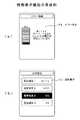
以下に情報表示機能16aによる情報表示の具体例を説明する。図5および図6は情報表示機能の具体例を示す説明図である。移動体2が電動アシスト機能を備えた自転車である場合、図1に示す移動体センサ機能6で例えば速度やバッテリの残量等が検出される。アタッチメントシステム3は第1の接続機能7を介して移動体センサ機能6で検出した速度等の移動体2の状態に関する情報を取得し、第1の通信手段8、情報変換機能11および第2の通信機能10により情報の加工や命令の付加等を行い、携帯端末4に対応した通信プロトコルに変換して第2の接続機能9を介して携帯端末4に送る。携帯端末4は通信機能13によりアタッチメントシステム3から情報を受信すると、情報変換機能14がインタフェース機能15を介して情報表示機能16aにより移動体2の状態を表示する。 A specific example of information display by the information display function 16a will be described below. 5 and 6 are explanatory diagrams showing specific examples of the information display function. When the moving
図5(a)は携帯端末4のディスプレイ50に速度やバッテリの状態等を表示する通常の表示形態例である。速度表示51としては、円形のメータ内で針の示す位置で速度の大小を表す形態と、文字で速度を表す形態を併用した例である。メータ表示には目盛りや項目名称、表示されている情報の単位等の情報を付加することで更に見やすくなる。また、携帯端末4のディスプレイ50はカラー表示を行えるものが一般的であるので、カラー表示を用いても良い。文字による情報の表示は情報の重要度等に合わせてフォントやフォントサイズを変更しても良い。 FIG. 5A shows an example of a normal display form in which the speed, battery state, and the like are displayed on the display 50 of the
バッテリ状態表示52としては、バッテリ残量を模式的な図で表すとともに、走行による放電中であるとか、回生制動による充電中である等の情報の表示を行う。なお、図で情報を表示する場合は静止画であっても良いし、例えば走行中であることを示すためにタイヤを回転させるような動画でも良い。 As the battery status display 52, the remaining amount of battery is schematically shown, and information such as whether the battery is being discharged by running or being charged by regenerative braking is displayed. In addition, when displaying information with a figure, a still image may be sufficient, for example, the moving image which rotates a tire in order to show that it is drive | working may be sufficient.
更に、携帯端末4のディスプレイ50に一度に表示できる情報量は限られていることから、図1に示す情報入力機能16bを実現する図示しないボタン等を操作することで、利用者が取得したい情報を表示できるようにする。 Furthermore, since the amount of information that can be displayed at once on the display 50 of the
すなわち、利用者が取得したい移動体2の各種状態情報を、図1に示す移動体センサ機能6で検出した移動体2の状態に応じて表示する機能を備える。例えば、利用者の選択に応じて図5(b)に示す空気圧表示53のようにタイヤの空気圧の情報を文字や模式的な図等で表示する。 That is, it has a function of displaying various state information of the moving
また、図1に示す移動体センサ機能6で検出した移動体2の状態に応じて、表示を自動的に切り換える機能を備える。例えば、バッテリの残量(電圧)が規定値より少なくなると、自動的に図6(a)に示すエラー表示54のようにバッテリの残量が不足している旨を文字や模式的や図で表示する。 Further, a function of automatically switching the display according to the state of the moving
更に、移動体2において設定変更が可能な項目の一覧を表示する機能を備える。例えば、利用者の選択に応じて図6(b)に示す設定表示55のように設定項目を特定する情報と設定内容を対応付けて表示する。設定変更すべく選択された項目や、設定変更が可能な項目を利用者が認識できるように強調表示するため、黒色の文字を黒を背景にした白抜き文字とするような反転表示や、色を変える等の表示、さらには点滅表示等を行っても良い。 Furthermore, the
なお、図6(b)に示す設定画面を表示することで、図1に示す情報入力機能16bで入力された情報によって設定の変更が可能である。すなわち、情報入力機能16bで入力された情報はインタフェース機能15により情報変換機能14に送られ、情報変換機能14および通信機能13により処理されて第2の接続機能9を介してアタッチメントシステム3に送られる。 By displaying the setting screen shown in FIG. 6B, the setting can be changed according to the information input by the information input function 16b shown in FIG. That is, the information input by the information input function 16 b is sent to the
アタッチメントシステム3は第2の通信機能10、情報変換機能11および第1の通信機能8により情報の加工や命令の付加等を行い、移動体2に対応した通信プロトコルに変換して第1の接続機能7を介して移動体2に送る。そして、移動体2の移動体制御機能5が設定の変更を行う。 The
図7は情報変換機能の変形例を示す説明図である。図7(a)は円や扇形内の針56の角度で速度等の情報の大小を表す形態である。メータの形状は円でも楕円でもよく、図7(a−1)に示すように扇形でメータの形状を表示する場合、扇形の形状はどの様なものであっても良い。 FIG. 7 is an explanatory diagram showing a modification of the information conversion function. FIG. 7A shows a form in which information such as speed is represented by the angle of the needle 56 in a circle or a sector. The shape of the meter may be a circle or an ellipse, and when the shape of the meter is displayed in a sector shape as shown in FIG. 7 (a-1), the shape of the sector shape may be any.
また、図7(a−2)に示すように、時計の長針短針同様に針の長さで情報項目を表し、その角度で情報の大小を表示しても良い。更に、図7(a−3)に示すように、情報の大小を示す数字を表示しても良い。また、図7(a−4)に示すように、扇型の角度や面積で情報の大小を表示しても良い。 Further, as shown in FIG. 7A-2, the information items may be represented by the length of the hands like the long hand and the short hand of the timepiece, and the magnitude of the information may be displayed by the angle. Furthermore, as shown in FIG. 7A-3, a number indicating the magnitude of the information may be displayed. Further, as shown in FIG. 7A-4, the magnitude of information may be displayed with a fan-shaped angle or area.
図7(b)は線長で情報の大小を表す形態で、図7(b−1)に示すように直線のバー表示57の線長や図7(b−2)に示す曲線のバー表示の線長で情報の大小を表示する。バー表示としては円弧形状でも良く、また、バー表示の向きとしては、縦、横、斜線のいずれでも良い。 FIG. 7B shows the size of information in line length. As shown in FIG. 7B-1, the line length of the straight bar display 57 and the curved bar display shown in FIG. 7B-2. The size of the information is displayed with the line length. The bar display may be an arc shape, and the direction of the bar display may be any of vertical, horizontal, and diagonal lines.
更に、これらの組み合わせのバー表示の線長で情報の大小を表しても良く、見やすくするための応用としてバー表示の線を太くしたり、カラー表示としても良い。なお、図7の表示形態でも、目盛りや項目名称、表示されている情報の単位等の情報を付加することで更に見やすくなる。 Further, the bar display line length of these combinations may represent the magnitude of information, and the bar display lines may be thickened or color display as an application for easy viewing. In the display form of FIG. 7, it is easier to see by adding information such as scales, item names, and units of displayed information.
その他、図示しないがエラー表示としては、図6(a)に示す形態の他に、移動体2の概要的な図を表示するとともに、故障箇所を点滅表示する等により利用者に通知する形態や、更にエラー要因の文字表示を追加する形態でも良い。また、エラー解析時等には管理図やチェックシートや系統図の形態で表示しても良い。 In addition to the form shown in FIG. 6A, as an error display (not shown), a schematic diagram of the
また、移動体2が多輪車の複数の駆動力を変更できる構成を備える場合は、パレート図の様にどこに駆動力や制動力がかかっているかを表示したり、加速度や速度を進行方向に対しどの様にかかっているかを散布図等の様にグラフ化しても良い。更に過去データを記録し、ヒストグラムの様に過去からの変化を表示しても良い。情報を棒や面積で表すのみならず、点等で表し、複数の情報を一元化するグラフ化をしても良い。 In addition, when the moving
(7)外部記憶機能の構成
図1に示す外部記憶機能19は持ち運びが容易で、不揮発性かつランダムアクセスが可能な小型のメモリで実現される。このようなメモリは、例えば、メモリスティック(R)シリーズや、コンパクトフラッシュ(R)メモリ等の小型のカード型記録媒体である。また、PCMCIA(personal computer memory card international association)が規格したカード型記憶装置(PCカード)である。更に、フラッシュメモリやEEPROMメモリ(electrically erasable and programmable read only memory)を組み込んだUSBメモリである。(7) Configuration of External Storage Function The
アタッチメントシステム3の第2の接続機能9は、外部記憶機能19を接続するためには、USBコネクタや各種カード型記録媒体に対応したスロットを備えれば良い。更に、携帯端末4からアタッチメントシステム3の情報変換機能11を介すことなく、外部記憶機能19で情報の保存ができるようにバス構成等を取れる通信規格で第2の接続機能9が構成される。 The
そして、携帯端末4に外部記憶機能19を直接接続するため、情報変換機能14は通信機能13に読み出しや書き込み依頼を記憶領域のアドレス情報とともに伝送し、通信機能13から第2の接続機能9へ情報が変換またはそのまま伝送され、伝送された情報が外部記憶機能19によって例えばメモリスティック(R)に記憶される。ここでメモリスティック(R)シリーズとは、メモリスティックDuo(R)、メモリスティックプロ(R)、メモリスティック(R)等を表す。 Then, in order to directly connect the
変形例として、命令を実行する機能を持たない外部記憶機能19の場合、通信機能13がアドレスに相当する情報とアドレスに相当する場所の情報を読むのか書き込むのかのW(ライト)/R(リード)情報と、情報を書き込む場合、書き込む情報とを伝送する。 As a modification, in the case of the
また、携帯端末4も記憶機能を持つことから、情報を保存する場合は、アタッチメントシステム3に接続された外部記憶機能19に情報を保存(書き込み)しても、携帯端末4側の記憶機能に情報を保存しても良い。 Since the
保存する情報の例を挙げれば、ビットマップ等の画像情報や、ワイヤフレームや絵や文字情報等の情報、動画や音情報や、移動体2のセットアップ情報や、移動体2を利用した利用者の情報である。 Examples of information to be stored include image information such as bitmap, information such as wire frame, picture and character information, video and sound information, setup information of the
移動体2のセットアップ情報の具体例の一部を挙げると、移動体2の変速機の自動変速時の速度情報や、明るさに応じて自動でライトを点灯させるか、必ずマニュアルで行うかといった設定情報や、前回移動体2を利用した際に表示項目や音情報として選んだ項目とその表示方法や音情報といった情報である。 Some examples of the setup information of the
(8)外部装置の構成
図1に示す外部装置18は一般的なパーソナルコンピュータに接続することができる汎用の外部接続機器で実現される。このような外部装置18は、例えば、キーボード、マウス、CCD(charge coupled device)のカメラ、C−MOS(complementary metal oxide semiconductor)のカメラ、タブレット、カードリーダ、スキャナ等の入力装置である。またモデム、ハブ、ルータ等の通信装置である。(8) Configuration of External Device The
更に、CD(Compact Disc)−ROM、DVD(Digital Versatile Disc)−ROM、DVD−R、DVD+R、DVD−RAM、マルチドライブと呼ばれる各種DVDを再生したり、情報保存できる機器、オーディオ装置等の記録再生装置や再生装置である。 Furthermore, CDs (Compact Discs) -ROMs, DVDs (Digital Versatile Discs) -ROMs, DVD-Rs, DVD + Rs, DVD-RAMs, recording devices such as multi-drives, devices that can store information, audio devices, etc. A playback device or a playback device.
また、プリンタ等の出力装置、オシロスコープ等の計測器である。なお、アタッチメントシステム3に供給される電源と第2の接続機能9を実現するコネクタを利用して、外部装置18として携帯端末4のバッテリ充電装置や、扇風機等を接続する形態も考えられる。 Also, it is an output device such as a printer or a measuring instrument such as an oscilloscope. In addition, the form which connects the battery charging apparatus of the
更に、アタッチメントシステム3が具備する以外の通信プロトコルへ変換する機器、例えばテレビチューナや、映像入出力機能機器、表示機能機器等を外部装置18として接続する形態も考えられる。この場合、携帯端末4の情報送受信用のプロトコル、例えば、IEEE802、Bluetooth等の無線接続や、USB等のバス構成が取れる有線接続にて情報が送受信できる装置で接続し、情報の送受信を行うことで動作させることができる。 Furthermore, a configuration in which a device that converts to a communication protocol other than that included in the
以上の(1)〜(8)の構成により本実施の形態の移動体通信システム1が構成される。このシステムはソフトウエアのみで実現しても良く、ハードウエアのみでも実現しても良く、ソフトウエアとハードウエアとを混在しても良い。 The
(9)移動体通信システムの動作
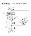
次に、本実施の形態の移動体通信システム1の動作について説明する。図8は本実施の形態の移動体通信システム1の全体の処理の流れを示すフローチャートである。(9) Operation of Mobile Communication System Next, the operation of the
ステップSA1の起動ルーチンとステップSA2の起動ルーチンチェックは、アタッチメントシステム3および携帯端末4の各機能が動作可能な状態かをチェックし、各機能が正常であればステップSA3の各種データ処理へ移行する。 The activation routine in step SA1 and the activation routine check in step SA2 check whether each function of the
これに対して、システムとして動作する際、致命的となり得るNG項目があった場合はステップSA4に移行し、NGが2回目であるかチェックする。ステップSA4でNGが1回目であると判断すると、ステップSA1に戻り、再度起動ルーチンを実行する。そして、ステップSA4で再度NGとなった場合は、ステップSA5の終了処理に移行する。 On the other hand, when there is an NG item that can be fatal when operating as a system, the process proceeds to step SA4 to check whether NG is the second time. If it is determined in step SA4 that NG is the first time, the process returns to step SA1 and the activation routine is executed again. And when it becomes NG again in step SA4, it transfers to the completion | finish process of step SA5.
なお、ステップSA1,SA2の起動ルーチンおよびチェックでNGとなり得る要因は通信エラー等であり、アタッチメントシステム3の第1の通信機能8や第2の通信機能10、あるいは第1の接続機能7や第2の接続機能9が動作していない場合等に起こる。 Note that a factor that can be NG in the startup routines and checks in steps SA1 and SA2 is a communication error or the like, and the
ステップSA5の終了処理は、アタッチメントシステム3の第2の通信機能10および携帯端末4の通信機能13を停止し、移動体センサ機能6の各センサのアタッチメントシステム3に対する出力および携帯端末4のアタッチメントシステム3に対する出力に応答しない状態とする。終了処理を始めると、終了処理を始めたときの状態を外部記憶機能19等で保存する。 In the end process of step SA5, the
情報変換機能11はスイッチによるON/OFFを監視するか、移動体2が稼動可能な状態にある場合は常に動作しており、移動体制御機能5から第2の通信機能10をONさせる命令がくるまで待機する。なお、ステップSA2のエラー処理時のエラーの内容によって、利用者にエラー内容を通知する機能が動作しても良い。 The
図9は起動ルーチンの一例を示すフローチャートである。ステップSB1の電源電圧確認とステップSB2の電源電圧確認チェックは、アタッチメントシステム3の電源電圧が正常であるかをチェックする。電源電圧が正常であればステップSB3の情報変換機能確認およびステップSB4の情報変換機能確認チェックへ移行する。 FIG. 9 is a flowchart showing an example of a startup routine. The power supply voltage confirmation in step SB1 and the power supply voltage confirmation check in step SB2 check whether the power supply voltage of the
これに対して電源電圧が異常である場合はステップSB5へ移行し、電源電圧確認でのNGが2回目であるかチェックする。ステップSB5でNGが1回目であると判断するとステップSB1に戻り、再度電源電圧チェックを実行する。ステップSB5で再度NGとなった場合は、図8のステップSA5の終了処理に移行する。 On the other hand, if the power supply voltage is abnormal, the process proceeds to step SB5, where it is checked whether NG in the power supply voltage confirmation is the second time. If it is determined in step SB5 that NG is the first time, the process returns to step SB1, and the power supply voltage check is performed again. When it becomes NG again in step SB5, the process proceeds to the end process of step SA5 in FIG.
ステップSB3の情報変換機能確認とステップSB4の情報変換機能確認チェックは、アタッチメントシステム3の情報変換機能11が正常であるかをチェックする。情報変換機能11が正常であればステップSB6の通信機能確認およびステップSB7の通信機能確認チェックへ移行する。 The information conversion function confirmation in step SB3 and the information conversion function confirmation check in step SB4 check whether the
これに対して情報変換機能11が異常である場合はステップSB8へ移行し、情報変換機能でのNGが2回目であるかチェックする。ステップSB8でNGが1回目であると判断するとステップSB3に戻り、再度情報変換機能11のチェックを実行する。ステップSB8で再度NGとなった場合は、図8のステップSA5の終了処理に移行する。 On the other hand, if the
ステップSB6の通信機能確認とステップSB7の通信機能確認チェックは、アタッチメントシステム3の第1の通信機能8と第2の通信機能10が正常であるかをチェックする。第1の通信機能8と第2の通信機能10の双方が正常であれば図8のステップSA3の各種データ処理へ移行する。 The communication function confirmation in step SB6 and the communication function confirmation check in step SB7 check whether the
これに対して第1の通信機能8と第2の通信機能10の何れか一方でも異常である場合はステップSB9へ移行し、通信機能でのNGが2回目であるかチェックする。ステップSB9でNGが1回目であると判断するとステップSB6に戻り、再度通信機能のチェックを実行する。ステップSB9で再度NGとなった場合は、図8のステップSA5の終了処理に移行する。 On the other hand, if any one of the
なお、この起動ルーチンでは、後述するように携帯端末4の起動およびチェックを行う形態もある。 In this activation routine, there is also a form in which the
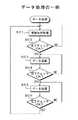
図10はデータ処理の一例を示すフローチャートである。ステップSC1の情報取得処理とステップSC2の完了チェックは、アタッチメントシステム3が移動体センサ機能6の各センサから情報を取得したかチェックする。情報の取得が完了するとステップSC3のデータ演算およびステップSC4の完了チェックへ移行する。情報の取得が完了していない場合はステップSC1に戻り、情報の取得を続ける。 FIG. 10 is a flowchart showing an example of data processing. The information acquisition process in step SC1 and the completion check in step SC2 check whether the
ステップSC3のデータ演算とステップSC4の完了チェックは、ステップSC1で取得した情報を携帯端末4で出力できるように演算を行う。情報の演算が完了するとステップSC5のデータ処理およびステップSC6の完了チェックへ移行する。情報の演算が完了していない場合はステップSC3に戻り、情報の演算を続ける。 The data calculation in step SC3 and the completion check in step SC4 are performed so that the information acquired in step SC1 can be output by the
ステップSC5のデータ処理とステップSC6の完了チェックは、ステップSC1で取得した情報を携帯端末4で出力する処理を行う。情報の出力処理が完了するとステップSC1に戻り、次の情報の取得を行う。情報の出力処理が完了していない場合はステップSC5に戻り、情報の出力処理を続ける。 The data processing in step SC5 and the completion check in step SC6 perform processing for outputting the information acquired in step SC1 on the
具体的には、例えばセンサを移動体2において何らかの操作を行うスイッチとし、実行しようとする処理をスイッチ操作による入力情報に応じた描画や音出力を携帯端末4で行う処理とすると、移動体2のスイッチが操作されることでアタッチメントシステム3は第1の接続機能7を介してスイッチ操作に応じた情報を取得する(ステップSC1,SC2)。 Specifically, for example, when the sensor is a switch that performs some operation on the
アタッチメントシステム3は第1の通信手段8、情報変換機能11および第2の通信機能10により情報の加工や命令の付加等の演算を行い、携帯端末4に対応した通信プロトコルに変換して第2の接続機能9を介して携帯端末4に送る(ステップSC3,ステップSC4)。 The
携帯端末4は通信機能13によりアタッチメントシステム3から情報を受信すると、情報変換機能14はスイッチ操作に応じた描画あるいは音を発生させる命令をインタフェース機能15に出す。これにより、情報表示機能16aでスイッチ操作に応じた情報が表示される。または、音発生機能17でスイッチ操作に応じた情報が音で出力される(ステップSC5,ステップSC6)。 When the
上述したデータ処理の変形例としては、演算後の結果に基づき判定処理等を行い、判定結果に基づき表示機能等を動作させることとしても良い。また、情報を演算し、演算結果を表示させるためにインタフェース機能15等を利用し表示させる命令を出すといった動作も可能である。 As a modified example of the above-described data processing, determination processing or the like may be performed based on the result after calculation, and a display function or the like may be operated based on the determination result. In addition, an operation of calculating information and issuing a command to display using the interface function 15 or the like to display the calculation result is also possible.
更に、演算と処理を1回または複数回行うにあたり、組み合わせや順番を変更しても良い。また、処理回数や演算を3回以上行っても良く、その際特定の順番を入れ替えても良い。更に、演算又は処理のどちらかを行わなくても良い。 Furthermore, the combination and order may be changed when performing the calculation and processing once or a plurality of times. In addition, the number of times of processing and the calculation may be performed three times or more, and a specific order may be switched at that time. Furthermore, it is not necessary to perform either calculation or processing.
図11は終了処理の一例を示すフローチャートである。ステップSD1の通信機能オフ処理とステップSD2の完了チェックは、アタッチメントシステム3の第2の通信機能10および携帯端末4の通信機能13を停止する。通信機能の停止が正常に完了するとステップSD3の情報変換機能待機処理およびステップSD4の完了チェックに移行する。第2の通信機能10および通信機能13を正常に停止できない場合はステップSD5へ移行し、エラー処理を行う。 FIG. 11 is a flowchart showing an example of the end process. The communication function OFF process in step SD1 and the completion check in step SD2 stop the
ステップSD3の情報変換機能待機処理とステップSD4の完了チェックは、アタッチメントシステム3の情報変換機能11を待機状態とする。すなわち、情報変換機能11でスイッチによるON/OFFを監視する状態とする。あるいは移動体2が稼動可能な状態にある場合は情報変換機能11を動作させ、移動体制御機能5からの第2の通信機能10をONさせる命令を受信できる状態とする。 In the information conversion function standby process in step SD3 and the completion check in step SD4, the
情報変換機能11の待機状態への移行が正常に完了するとステップSD6の不要電圧の処理およびステップSD7の完了チェックに移行する。情報変換機能11を待機状態へ移行できない場合はステップSD5へ移行し、エラー処理を行う。 When the transition to the standby state of the
ステップSD6の不要電圧の処理とステップSD7の完了チェックは、情報変換機能11による待機動作に不要な電圧の供給を制御する処理を行い、正常に完了できれば終了処理を終了する。不要電圧の処理を完了できない場合はステップSD5に移行し、エラー処理を行う。ステップSD5のエラー処理は、例えばエラーの内容によって利用者にエラー内容を知らせる。 In the process of unnecessary voltage in step SD6 and the completion check in step SD7, a process for controlling the supply of a voltage unnecessary for the standby operation by the
以上のように、アタッチメントシステム3と携帯端末4との間でデータを送受信し、表示内容の更新等を繰り返し、処理が終了すると終了処理を行う。ここで、どの処理ステップでも外部からの割り込みが入る。例えば携帯端末4として携帯電話を用いる場合は、着信が割り込みとなる。また、携帯端末4がPDAやPCの場合はCPU等からの上位命令が割り込みとなる。割り込みが入った場合は、アタッチメントシステム3と携帯端末4との間の通信を停止するため、割り込みにより処理を中断する旨を携帯端末4からアタッチメントシステム3に送信する。 As described above, data is transmitted / received between the
図12はデータの流れの具体例を示すフローチャートで、上述したように移動体2と携帯端末4との間で情報を送受して処理を行う際のアタッチメントシステム3と携帯端末4との間でのデータの流れを説明する。 FIG. 12 is a flowchart showing a specific example of the flow of data. As described above, between the
まず、起動ルーチンから説明すると、移動体2のアタッチメントシステム3は、ステップSE1の起動ルーチンとステップSE2の起動チェックで移動体2と携帯端末4が起動しているか、携帯端末4は移動体2の情報を受けられる状態か等をチェックする。すなわち、アタッチメントシステム3は携帯端末4に所定のコマンドを送る。携帯端末4はステップSE3でコマンドに応答する。 First, the start-up routine will be described. In the
ここで、携帯端末4にはリモートで電源管理やソフトウエアの起動ができるものがある。このような場合、アタッチメントシステム3からの命令で携帯端末4の電源投入からセットアップまでを行い、起動が完了したかをステップSE2の起動チェックで行うことになる。このため起動チェックの判断結果1では、何が起動していないか示す処理用フラグ等を戻す。 Here, some
次にデータ処理を説明する。本例では、移動体2から携帯端末4に情報を送り、情報表示機能16aで表示する処理を説明する。まず、アタッチメントシステム3はステップSE4のデータ送信処理で表示する情報のデータを送信する。携帯端末4はステップSE5のデータ受信処理と受信完了返信処理でアタッチメント3からデータを受信し、受信が完了した旨のデータをアタッチメント3に返信する。 Next, data processing will be described. In this example, a process of sending information from the moving
更に携帯端末4はステップSE6のデータチェックで送られてきたデータがどんなデータか、データは壊れていないか、データの中身を確認する。そして、ステップSE6のデータチェックでデータが正常に送られてきていれば、ステップSE7に移行し情報表示機能16aによって表示を行い、表示が完了した旨を返送する。また、データが正常に送られていない場合はステップSE8に移行し、データの再送依頼を返信する。 Further, the
アタッチメントシステム3はステップSE9の受信処理とステップSE10の完了チェックで、携帯端末4からの返信が再送依頼のデータか、正常に処理ができた旨のデータかを確認する。よって完了チェックの判断結果2はデータの表示ができたか、できていないならば何ができていないかをステップSE4のデータ送信処理へ戻す。これにより、アタッチメントシステム3は、データの再送依頼を受けた場合はステップSE4で再度データを送信する。また、正常にデータが表示された場合はステップSE4で次のデータを送信する。 The
(10)設定確認および設定変更
以上説明したように、アタッチメントシステム3に携帯端末4を接続することで、アタッチメントシステム3を介して移動体2と携帯端末4との間で情報の送受が行われる。これにより、図6(b)で説明したように設定に関する情報を表示して携帯端末4で移動体2の各種設定の確認が可能となる。また、情報入力機能16bで入力した情報で携帯端末4から移動体2の設定の変更が可能となる。(10) Setting confirmation and setting change As described above, by connecting the
移動体2の設定として、走行に関連する設定情報は、使用者が移動体2を快適に利用できるかどうかを示す指標となる。このため、例えば自動変速機の変速ポイントにおけるある範囲内の速度や、移動体2として装備できるある範囲内のタイヤ径およびある範囲内のホイール径を設定情報として表示する。また、移動体の動作できるある範囲内の最大加速度の大きさ、ある範囲内における通常時の加速度の大きさを設定情報として表示する。 As the setting of the
これら設定情報はデフォルトで決定されている値が表示され、利用者が移動体2を利用する際に参照できるようにする。例えば、設定情報を確認することで、利用者はタイヤを交換する際に最適なタイヤを選択可能となる。 Values set by default are displayed as these setting information so that the user can refer to them when using the
更に、走行に関連する設定情報としては走行方法を決定するモード情報を表示する。このモード情報はいくつかの走行モードの中から利用者が所望する走行モードを選択可能とすることができる。 Further, mode information for determining a traveling method is displayed as setting information related to traveling. This mode information can make it possible to select a travel mode desired by the user from among several travel modes.
また、移動体2に様々なスイッチが備えられている場合、ON/OFF等の確認や、切り換えが携帯端末4で可能となる。例えば、デフォルトでAUTOやONやOFFとするかどうかといったセットアップ情報、電子スイッチの状態を示すON/OFF情報を設定情報として表示する。 In addition, when the
また、スイッチ機能を状況に応じて自動で切り換えるか手動で切り換えるかの選択変更情報、ユーザインタフェースとしては機械式で電子制御となっているスイッチの状態を示すON/OFF情報とその制御内容を設定情報として表示する。移動体2はこれらの設定を携帯端末4の情報入力機能16bで入力された情報で変更する。また、設定の変更は表示に反映される。 Also, selection change information on whether to switch the switch function automatically or manually according to the situation, ON / OFF information indicating the state of the switch that is mechanically and electronically controlled as the user interface, and its control contents are set Display as information. The
更に、時刻設定、決まった時刻に音や光や振動といった認識可能な手段で通知するアラーム設定、警告音等の曲データ設定等を設定情報として表示し、これらの設定を携帯端末4の情報入力機能16bで入力された情報で変更する。また、図示しないナビゲーションシステムと併用して現在位置情報を表示することもできる。 Furthermore, the time setting, the alarm setting to be notified by a recognizable means such as sound, light and vibration at a fixed time, the music data setting such as warning sound, etc. are displayed as setting information, and these settings are input to the
(11)外部装置の利用
利用者が利用したい外部装置18の例としては、利用者名やパスワードや利用者網膜情報や電子キー、指紋認証機、タブレットやキーボード、マウス、視線確認装置といった移動体用としては既存の物がないが携帯端末4としては既存の物がある入力装置等である。(11) Use of external device Examples of the
更に、応用例として携帯端末4との接続機能を、アタッチメントシステム3に内包するのみならず、接続機能を別体とすることで、アタッチメントシステム周りの接続線を簡素化することができる。 Furthermore, as an application example, not only the connection function with the
(12)外部記憶装置の利用
外部記憶機能19には情報を書き込むこととしたが、外部記憶機能19に正常に動作するための準備が完了したデバイスのログを書き込んでおけば、移動体2の製造工場、移動体2の整備工場、メンテナンスをする一般利用者等が携帯情報端末4等で外部記憶機能19で記録したログ情報を調べることができる。これにより、移動体2や通信接続やアタッチメントシステム3に不具合がある場合、何で障害が発生しているか又は何が正しく動作しているかを認識可能となる。なお説明はソフトウエアで実現する形態で記載しているが、同様の処理をハードウエアのみまたはハードウエアにソフトウエアを内蔵する形態で実現しても良い。(12) Use of external storage device Information is written to the
(13)制御ソフトウエアの例
図13はアタッチメントシステムを実現するソフトウエア例で、アタッチメントシステムを実現するにあたりソフトウエアを使用した場合、その使用言語とその命令系統の違いを表した例である。(13) Example of Control Software FIG. 13 is an example of software that realizes an attachment system. When software is used to realize the attachment system, the example shows the difference between the language used and the instruction system.
図13で示した間接命令型とは、一般にブラウザと称されるソフトウエアを利用することであり、利用者の携帯端末4が命令をブラウザ等にてハードウエア動作用動作命令に変換し、命令を実行できるものの例である。ブラウザ等を利用することで、全く異なる端末等ハードウエアのものでも同種の機能を備えている物であればほぼ同じ結果を得ることが可能となる。 The indirect command type shown in FIG. 13 is to use software generally called a browser, and the user's
これに対して直接命令型とは特定のシステムのみを介し利用者が命令実行環境を持つ場合にのみ実現可能なもの等のことである。アタッチメントシステムを構成するにあたり基本の処理したい内容は同じであることから、上記どちらで実現しても良い。 On the other hand, the direct instruction type is something that can be realized only when the user has an instruction execution environment only through a specific system. Since the basic contents to be processed in configuring the attachment system are the same, either of the above may be realized.
(14)設置
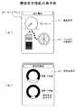
図14はアタッチメントシステム3および携帯端末4の設置例を示す説明図である。図14では、移動体2はオートバイや自転車、特に電動アシスト機能を備えた自転車等で、ハンドル60にアタッチメントシステム3を固定する例である。(14) Installation FIG. 14 is an explanatory diagram showing an installation example of the
ハンドル60は中央部がハンドルステムのクランプ部61に固定される。なお、図14ではハンドル60は湾曲等の無いバー形式のものを図示しているが、湾曲のあるハンドルでも良い。 The center of the
図14(a),(b)はアタッチメントシステム3をハンドル60のクランプ部61より左側のいずれかの位置に固定する形態である。また、図14(c)はアタッチメントシステム3をハンドル60の中央部、例えばクランプ部61に固定する形態である。更に、図14(d)はアタッチメントシステム3をハンドル60のクランプ部61より右側のいずれかの位置に固定する形態である。 14A and 14B show a form in which the
なお、図14ではハンドル60の幅と携帯端末4の大きさの関係を模式的に示すが、図14(a)ではハンドル60の端部にアタッチメントシステム3を固定した例を示す。また、図14(b)はハンドル60の中央部付近にアタッチメントシステム3を固定した例を示す。更に、図14(d)はハンドル60の端部と中央部の中間付近にアタッチメントシステム3を固定した例を示す。 FIG. 14 schematically shows the relationship between the width of the
図示はしないが、ハンドル60のクランプ部61より左側で端部と中央部の中間付近にアタッチメントシステム3を固定しても良い。同様に、ハンドル60のクランプ部61より右側で端部、あるいは中央部付近にアタッチメントシステム3を固定しても良い。このように、移動体2が2輪車であればであれば、利用者が操作しやすい位置に応じて、ハンドル60の任意の位置にアタッチメントシステム3を固定することができる。 Although not shown, the
ここで、図1に示す第1の接続機能7は、アタッチメントシステム3と移動体2の移動体制御機能5および移動体センサ機能6を有線で接続する形態であれば、ケーブル62等で実現される。ケーブル62は例えば一般的なハンドル60の幅に応じて長さを設定し、アタッチメントシステム3を固定する位置に応じてハンドル60に巻きつける等によって長さを調整する。 Here, the
携帯端末4としては図1に示す情報表示機能16aとしてディスプレイ50を備えた携帯電話を例にしている。図1に示す第2の接続機能9は、例えば携帯端末4とアタッチメントシステム3にコネクタ63を備え、コネクタ同士を直接接続する形態で実現される。なお、ケーブルとコネクタで有線により接続する形態や、赤外線等の光通信の形態で実現しても良い。更に、携帯端末4はアンテナ64を備え、このアンテナ64とアタッチメントシステム3に備えた図示しないアンテナで無線により接続する形態で第2の接続機能9を実現しても良い。 As the
また、一般的に携帯電話やPDA等のディスプレイは長方形であるが、図14に示すようにディスプレイ50が縦長となる向きで携帯端末4を固定できるようにしても良いし、ディスプレイ50が横長となる向きで携帯端末4を固定できるようにしても良い。 In general, a display such as a mobile phone or a PDA has a rectangular shape. However, as shown in FIG. 14, the
以上説明した図14では2輪車等のハンドル60のように端が存在する形状のものにアタッチメントシステム3を設置する例を示したが、応用設置例として、4輪車のハンドルのように端の存在しないハンドルの場合は、ハンドルを構成する辺や弧状の部位にアタッチメントシステム3を設置しても良い。また、4輪車等において時計や各種メータパネル等の窪みや、新たに窪みを設けて、この窪みにアタッチメントシステム3を設置しても良い。 FIG. 14 described above shows an example in which the
更に、シフトレバーの上、ダッシュボードの中、センターコンソールボックスやアームレスト、その他小物等を収納可能な場所にアタッチメントシステム3を設置しても良い。 Further, the
このように、アタッチメントシステム3に固定手段として各種設置用取付金具を取り付けて、移動体2に対する取付位置を自由に選べるようにする。また、アタッチメントシステム3を移動体2に予め組み込んでおく形態でも良い。 In this way, various mounting brackets are attached to the
また、電子機器である携帯端末4は使用時に発熱するので、冷却が行えるようにアタッチメントシステム3をエアコンの吹き出し口に設置する形態も考えられる。但しエアコンの吹き出し口の近くにアタッチメントシステム3ならびに携帯端末4を設置すると、装置内部にて結露する可能性がある。 In addition, since the
このため、エアコンの吹き出し口の近くに設置する場合の応用例として、直接風によって携帯端末4は冷却されず、アタッチメントシステム3が冷えることでアタッチメントシステム3に設置された携帯端末4の熱が移動し、携帯端末4が冷えるという形態が考えられる。更に、アタッチメントシステム3自体の結露対策は、アタッチメントシステム3内部を封止する等の結露対策を行っても良い。 For this reason, as an application example in the case of installing near the air outlet of the air conditioner, the
ここで、アタッチメントシステム3は既存のアタッチメントとしての機能を持つため、携帯端末4を固定するための機構部は既存の固定機能と、衝撃等に対する保護機能を持たせることができる。 Here, since the
既存のアタッチメントと違う点として、アタッチメントシステム3の内部に回路や機構が入るため、振動や水分や塵や埃より、アタッチメントシステム3の内部部品を保護する機能を付加すると良い。例えば、内部部品の周囲に緩衝材を備える。また、アタッチメントシステム3の筐体を弾力性のある材質で構成し、内部部品と携帯端末4を保護できるようにしても良い。 A difference from existing attachments is that a circuit or mechanism is placed inside the
更に、携帯端末4をカバーできる形態としても良い。このような形態では、情報表示機能を実現するディスプレイの直近は透明の物質を利用したり、ディスプレイ等を外部光線から保護する機能として屈折率による有害光線等の特定波長を中心としたある範囲の光線のみを反射や吸収する既存の構造を備えても良い。 Further, the
また、その他の機構として、例えば、固定手段として回転機能を1箇所以上備え、ストッパ機構又はロック機構と回転機構から構成され、各々の回転機構がストッパ等により角度を維持できる機能を備えても良い。 In addition, as another mechanism, for example, one or more rotation functions may be provided as fixing means, which may include a stopper mechanism or a lock mechanism and a rotation mechanism, and each rotation mechanism may have a function of maintaining an angle by a stopper or the like. .
(15)効果
以上説明したように、移動体2に備えられる従来のアタッチメントは携帯電話等の携帯端末を単に固定するために用いられ、固定時には携帯端末を有効に利用することができなかった。(15) Effect As described above, the conventional attachment provided in the moving
これに対して、本実施の形態の移動体通信システムおよび携帯端末装着装置では、携帯電話やPDA等の情報端末、携帯可能なゲーム機やウェアラブル機器等の携帯端末4をアタッチメントシステム3に装着することで、これら携帯端末4と移動体2との間で情報の送受が可能となり、移動体2の利用者に移動体情報の発信をするシステムの構築が容易に可能となる。 On the other hand, in the mobile communication system and the mobile terminal mounting device according to the present embodiment, the
移動体情報を利用者に提示する際、移動体2の通信システムは独自のプロトコルを採用しているため、従来は情報を伝達するためのハードウエアに大きく依存し、個別に対応するしかない部分が大多数を占めていた。 When presenting mobile unit information to a user, the communication system of the
これに対して、本実施の形態では、アタッチメントシステム3を例えば表1に示す間接命令型システムで構成することで、表示機能および音を発生させる機能はハードウエアにそれほど依存することなく、異なるハードウエアでもほぼ同じ結果を利用者に提示する事が可能となる。 On the other hand, in the present embodiment, the
これにより、利用者が従来より所有する携帯端末4を利用できるようにすることで、高機能な移動体情報を利用者に伝えることを可能とする情報表示、伝達システムを低コストで提供することが可能となる。 This provides a low-cost information display and transmission system that enables the user to use the
また、アタッチメントシステム3の携帯端末4との間の接続機能(第2の接続機能9)は、情報伝送経路としてバス構成をもつ標準化された通信規格を利用することができるため、更に他の外部機器を簡単に後付けすることができる。このように、アタッチメントシステム3を介することで標準化された通信規格の他の外部機器も接続できるので、安価な外部機器の利用が可能となり、発展性の高いシステムを安価に提供できる。 In addition, the connection function (second connection function 9) between the
具体的な運用例としては、移動体2を維持管理、修繕補修をする作業者が携帯端末4でログ情報やエラー情報等を容易に見ることができるようになる。また、アタッチメントシステム3に外部記憶装置を接続してログ情報やエラー情報等の蓄積および管理もできるようになるため、不良箇所の早期発見に役に立つ。更に、外部記憶装置として着脱自在な記憶メディアを用いる装置を利用すれば、ログ情報やエラー情報を記憶メディアに直接書き込むことが可能となる。 As a specific operation example, an operator who maintains and repairs and repairs the
これにより、エラー情報の入ったファイルをサービスシステムに容易に取り込むことができ、取得したエラー情報を用いてサービスシステムが自動解析を行って、不良と思われる箇所を容易にピックアップすることができる。更に、サービスや情報の共有が可能となる。よって、移動体2の故障時等に迅速に対処することが可能となる。 As a result, a file containing error information can be easily taken into the service system, and the service system can automatically analyze the acquired error information to easily pick up a portion that seems to be defective. Furthermore, services and information can be shared. Therefore, it is possible to quickly cope with a failure of the moving
また、2輪車等では収納スペースが限られるが、アタッチメントシステム3を取り付けることで、移動体2に乗車中でも今までであれば使用できなかった携帯端末4を有効に利用することが可能となる。 In addition, although a storage space is limited in a two-wheeled vehicle or the like, by attaching the
本発明は、自動車等の移動体が使用している情報を、移動体の利用者が所有している汎用の携帯端末に発信することができるので、安価な管理システムを提供することが可能となる。 Since the present invention can transmit information used by a moving body such as an automobile to a general-purpose portable terminal owned by a user of the moving body, it is possible to provide an inexpensive management system. Become.
1・・・移動体通信システム、2・・・移動体、3・・・アタッチメントシステム、4・・・携帯端末、5・・・移動体制御機能、6・・・移動体センサ機能、7・・・第1の接続機能、8・・・第1の通信機能、9・・・第2の接続機能、10・・・第2の通信機能、11・・・情報変換機能、12・・・音発生機能、13・・・通信機能、14・・・情報変換機能、15・・・インタフェース機能、16a・・・情報表示機能、16b・・・情報入力機能、17・・・音発生機能、18・・・外部装置、18a・・・データ通信線、19・・・外部記憶機能、20・・・コネクト部、21・・・通信線、22・・・プロトコル変換機能、23・・・電圧⇔電圧変換機能、24・・・電圧⇔電流変換機能、25・・・電圧⇔電波変換機能、26・・・電圧⇔光変換機能、27・・・A/D・D/A変換機能、28・・・情報取捨選択機能、29・・・コマンド⇔コマンド変換機能、30・・・コマンド⇔情報変換機能、31・・・A/D値⇔情報変換機能、32・・・情報⇔情報変換機能、33・・・アンプ機能、34・・・入出力機能、35・・・録音機能、36・・・認識機能、37・・・イコライザ機能、38・・・点灯機能、39・・・点滅機能、40・・・線描画機能、41・・・動画描画機能、42・・・文字描画機能、43・・・図形描画機能
DESCRIPTION OF
Claims (18)
Translated fromJapanese前記ゲートウエイ装置は、
外部接続手段および情報処理手段を有する携帯端末の前記外部接続手段と着脱自在に接続される接続手段と、
前記移動体の前記情報処理手段と前記携帯端末の前記情報処理手段との間で情報を変換して送受を行う通信制御手段と
を備えたことを特徴とする移動体通信システム。A mobile device having an information processing means is equipped with a gateway device,
The gateway device is
A connection means detachably connected to the external connection means of a portable terminal having external connection means and information processing means;
A mobile communication system comprising: a communication control unit configured to convert information between the information processing unit of the mobile unit and the information processing unit of the mobile terminal and transmit / receive information.
ことを特徴とする請求項1記載の移動体通信システム。The mobile communication system according to claim 1, further comprising mounting means for detachably mounting the portable terminal.
ことを特徴とする請求項1記載の移動体通信システム。The mobile communication system according to claim 1, wherein the connection means connects the portable terminal and the gateway device by wire.
ことを特徴とする請求項1記載の移動体通信システム。The mobile communication system according to claim 1, wherein the connection unit wirelessly connects the portable terminal and the gateway device.
ことを特徴とする請求項1記載の移動体通信システム。The mobile communication system according to claim 1, wherein the connection means is connected to the portable terminal in a bus configuration.
ことを特徴とする請求項1記載の移動体通信システム。The mobile communication system according to claim 1, wherein the communication control unit acquires information from the mobile unit and outputs the information from the information output unit of the portable terminal.
ことを特徴とする請求項6記載の移動体通信システム。The mobile communication system according to claim 6, wherein the information acquired from the mobile body by the communication control means is state information of the mobile body detected by the mobile body detection means.
前記通信制御手段は前記移動体から取得した情報を画像もしくは音のいずれか、あるいは画像と音の両方で出力する
ことを特徴とする請求項6記載の移動体通信システム。The information output means is either a display means for displaying an image and a sound generation means for outputting a sound, or both the display means and the sound generation means.
The mobile communication system according to claim 6, wherein the communication control unit outputs information acquired from the mobile body as either an image or a sound, or both an image and a sound.
ことを特徴とする請求項1記載の移動体通信システム。The mobile communication system according to claim 1, wherein the gateway device includes sound generation means for outputting sound, and outputs sound using sound information acquired from the portable terminal.
ことを特徴とする請求項1記載の移動体通信システム。The mobile unit according to claim 1, wherein the communication control unit acquires setting information input by an information input unit of the portable terminal and sets the mobile unit by the information processing unit of the mobile unit. Communications system.
ことを特徴とする請求項1記載の移動体通信システム。2. A storage means is connected to the gateway device, and stores information sent from the information processing means of the mobile body and information sent from the information processing means of the portable terminal. The mobile communication system described.
移動体の情報処理手段と接続されるゲートウエイ装置を備え、
前記ゲートウエイ装置は、
前記携帯端末の外部接続手段と着脱自在に接続される接続手段と、
前記移動体の前記情報処理手段と前記携帯端末の情報処理手段との間で情報を変換して送受を行う通信制御手段と
を備えたことを特徴とする携帯端末装着装置。A mounting means for detachably mounting the mobile terminal;
A gateway device connected to the information processing means of the mobile body;
The gateway device is
A connection means detachably connected to an external connection means of the portable terminal;
A mobile terminal mounting device comprising: communication control means for performing transmission and reception by converting information between the information processing means of the mobile body and the information processing means of the mobile terminal.
ことを特徴とする請求項12記載の携帯端末装着装置。The mobile terminal mounting apparatus according to claim 12, wherein the connection unit is connected to the mobile terminal by wire.
ことを特徴とする請求項12記載の携帯端末装着装置。The mobile terminal mounting apparatus according to claim 12, wherein the connection unit wirelessly connects to the mobile terminal.
ことを特徴とする請求項12記載の携帯端末装着装置。The mobile terminal mounting apparatus according to claim 12, wherein the connection unit is connected to the mobile terminal in a bus configuration.
ことを特徴とする請求項12記載の携帯端末装着装置。The mobile terminal mounting device according to claim 12, further comprising sound generating means for outputting sound.
ことを特徴とする請求項12記載の携帯端末装着装置。The mobile terminal mounting device according to claim 12, further comprising storage unit connection means to which the storage means is connected.
ことを特徴とする請求項12記載の携帯端末装着装置。
The mobile terminal mounting device according to claim 12, further comprising fixing means for fixing to the moving body.
Priority Applications (1)
| Application Number | Priority Date | Filing Date | Title |
|---|---|---|---|
| JP2003429363AJP2005191819A (en) | 2003-12-25 | 2003-12-25 | Mobile communication system and mobile terminal wearing device |
Applications Claiming Priority (1)
| Application Number | Priority Date | Filing Date | Title |
|---|---|---|---|
| JP2003429363AJP2005191819A (en) | 2003-12-25 | 2003-12-25 | Mobile communication system and mobile terminal wearing device |
Publications (1)
| Publication Number | Publication Date |
|---|---|
| JP2005191819Atrue JP2005191819A (en) | 2005-07-14 |
Family
ID=34788056
Family Applications (1)
| Application Number | Title | Priority Date | Filing Date |
|---|---|---|---|
| JP2003429363APendingJP2005191819A (en) | 2003-12-25 | 2003-12-25 | Mobile communication system and mobile terminal wearing device |
Country Status (1)
| Country | Link |
|---|---|
| JP (1) | JP2005191819A (en) |
Cited By (20)
| Publication number | Priority date | Publication date | Assignee | Title |
|---|---|---|---|---|
| JP2008083914A (en)* | 2006-09-27 | 2008-04-10 | Alpine Electronics Inc | Electronic apparatus having data reproduction function |
| WO2009084506A1 (en) | 2007-12-28 | 2009-07-09 | Sony Corporation | Communication device, communication system, communication method, and program |
| JP2009177637A (en)* | 2008-01-25 | 2009-08-06 | Sharp Corp | Terminal device and control method thereof, communication system, communication method, communication program, and recording medium |
| JP2009182459A (en)* | 2008-01-29 | 2009-08-13 | Sony Corp | Communication device, communication system, communication method, and program |
| JP2009182458A (en)* | 2008-01-29 | 2009-08-13 | Sony Corp | COMMUNICATION DEVICE, COMMUNICATION SYSTEM, COMMUNICATION METHOD, AND PROGRAM |
| EP2164229A1 (en) | 2008-08-20 | 2010-03-17 | Sony Corporation | Communication device, communication system, communication method and program |
| US20130211628A1 (en)* | 2011-03-11 | 2013-08-15 | Bradley R. Thurow | Vehicle control and gateway module |
| JP2013249026A (en)* | 2012-06-04 | 2013-12-12 | Honda Motor Co Ltd | Display device for vehicle |
| WO2014083773A1 (en)* | 2012-11-27 | 2014-06-05 | 株式会社デンソー | User interface device |
| JP2014120821A (en)* | 2012-12-13 | 2014-06-30 | Panasonic Corp | State display program and supply server program for external apparatus |
| CN105206027A (en)* | 2015-10-20 | 2015-12-30 | 秦皇岛首创思泰意达环保科技有限公司 | Mobile-controlled dust suppression device and method |
| US9324197B2 (en) | 2011-03-11 | 2016-04-26 | Intelligent Agricultural Soultions | Method and system for managing the hand-off between control terminals |
| CN105847501A (en)* | 2016-04-26 | 2016-08-10 | 广东每通测控科技股份有限公司 | A fully automatic streamlined mobile phone online testing method and system thereof |
| US9474208B2 (en) | 2011-11-15 | 2016-10-25 | Appareo Systems, Llc | System and method for determining material yield and/or loss from a harvesting machine using acoustic sensors |
| US9631964B2 (en) | 2011-03-11 | 2017-04-25 | Intelligent Agricultural Solutions, Llc | Acoustic material flow sensor |
| US9629308B2 (en) | 2011-03-11 | 2017-04-25 | Intelligent Agricultural Solutions, Llc | Harvesting machine capable of automatic adjustment |
| JP2018522779A (en)* | 2015-06-10 | 2018-08-16 | タイムティックス テクノロジーズ プライベート リミテッド | Smart tire pressure monitoring system |
| US10085379B2 (en) | 2014-09-12 | 2018-10-02 | Appareo Systems, Llc | Grain quality sensor |
| US10318138B2 (en) | 2011-03-11 | 2019-06-11 | Intelligent Agricultural Solutions Llc | Harvesting machine capable of automatic adjustment |
| US10321624B2 (en) | 2011-03-11 | 2019-06-18 | Intelligent Agriculture Solutions LLC | Air seeder manifold system |
- 2003
- 2003-12-25JPJP2003429363Apatent/JP2005191819A/enactivePending
Cited By (26)
| Publication number | Priority date | Publication date | Assignee | Title |
|---|---|---|---|---|
| JP2008083914A (en)* | 2006-09-27 | 2008-04-10 | Alpine Electronics Inc | Electronic apparatus having data reproduction function |
| WO2009084506A1 (en) | 2007-12-28 | 2009-07-09 | Sony Corporation | Communication device, communication system, communication method, and program |
| JP2009177637A (en)* | 2008-01-25 | 2009-08-06 | Sharp Corp | Terminal device and control method thereof, communication system, communication method, communication program, and recording medium |
| JP2009182459A (en)* | 2008-01-29 | 2009-08-13 | Sony Corp | Communication device, communication system, communication method, and program |
| JP2009182458A (en)* | 2008-01-29 | 2009-08-13 | Sony Corp | COMMUNICATION DEVICE, COMMUNICATION SYSTEM, COMMUNICATION METHOD, AND PROGRAM |
| US9591105B2 (en) | 2008-01-29 | 2017-03-07 | Sony Corporation | Communication apparatus, communication system, communication method, and program for improved data transfer efficiency |
| US8725074B2 (en) | 2008-08-20 | 2014-05-13 | Sony Corporation | Communication device, communication system, communication method and program |
| EP2164229A1 (en) | 2008-08-20 | 2010-03-17 | Sony Corporation | Communication device, communication system, communication method and program |
| US9631964B2 (en) | 2011-03-11 | 2017-04-25 | Intelligent Agricultural Solutions, Llc | Acoustic material flow sensor |
| US10321624B2 (en) | 2011-03-11 | 2019-06-18 | Intelligent Agriculture Solutions LLC | Air seeder manifold system |
| US10318138B2 (en) | 2011-03-11 | 2019-06-11 | Intelligent Agricultural Solutions Llc | Harvesting machine capable of automatic adjustment |
| US9629308B2 (en) | 2011-03-11 | 2017-04-25 | Intelligent Agricultural Solutions, Llc | Harvesting machine capable of automatic adjustment |
| US9324197B2 (en) | 2011-03-11 | 2016-04-26 | Intelligent Agricultural Soultions | Method and system for managing the hand-off between control terminals |
| US9330062B2 (en)* | 2011-03-11 | 2016-05-03 | Intelligent Agricultural Solutions, Llc | Vehicle control and gateway module |
| US20130211628A1 (en)* | 2011-03-11 | 2013-08-15 | Bradley R. Thurow | Vehicle control and gateway module |
| US9474208B2 (en) | 2011-11-15 | 2016-10-25 | Appareo Systems, Llc | System and method for determining material yield and/or loss from a harvesting machine using acoustic sensors |
| JP2013249026A (en)* | 2012-06-04 | 2013-12-12 | Honda Motor Co Ltd | Display device for vehicle |
| WO2014083773A1 (en)* | 2012-11-27 | 2014-06-05 | 株式会社デンソー | User interface device |
| US9937796B2 (en) | 2012-11-27 | 2018-04-10 | Denso Corporation | User interface device with light-emitter input switch |
| JP2014106717A (en)* | 2012-11-27 | 2014-06-09 | Denso Corp | User interface device |
| JP2014120821A (en)* | 2012-12-13 | 2014-06-30 | Panasonic Corp | State display program and supply server program for external apparatus |
| US10085379B2 (en) | 2014-09-12 | 2018-10-02 | Appareo Systems, Llc | Grain quality sensor |
| JP2018522779A (en)* | 2015-06-10 | 2018-08-16 | タイムティックス テクノロジーズ プライベート リミテッド | Smart tire pressure monitoring system |
| CN105206027A (en)* | 2015-10-20 | 2015-12-30 | 秦皇岛首创思泰意达环保科技有限公司 | Mobile-controlled dust suppression device and method |
| CN105847501A (en)* | 2016-04-26 | 2016-08-10 | 广东每通测控科技股份有限公司 | A fully automatic streamlined mobile phone online testing method and system thereof |
| CN105847501B (en)* | 2016-04-26 | 2018-12-25 | 广东每通测控科技股份有限公司 | Full-automatic streamline type mobile phone online testing method and system |
Similar Documents
| Publication | Publication Date | Title |
|---|---|---|
| JP2005191819A (en) | Mobile communication system and mobile terminal wearing device | |
| US10713937B2 (en) | Trainable transceiver and mobile communications device diagnostic systems and methods | |
| JP6448158B2 (en) | Method, server, mobile terminal, and apparatus for exchanging data with in-vehicle infotainment | |
| JP5000888B2 (en) | Communication method and communication system | |
| US9286265B2 (en) | Device and method for managing an electronic control unit of a vehicle | |
| US9330507B2 (en) | System and method for selecting individual parameters to transition from text-to-graph or graph-to-text | |
| KR101470206B1 (en) | Mobile-based General-Purpose Integrated Vehicle Control System | |
| US20120095643A1 (en) | Method, Apparatus, and Computer Program Product for Modifying a User Interface Format | |
| KR20180088643A (en) | Dynamic Reconfigurable Display Knob | |
| KR101876738B1 (en) | Vehicle user interface providing apparatus and method | |
| KR101648022B1 (en) | Vehicle and controlling method thereof | |
| JP2011077899A (en) | Display device, drive recorder, display method and program | |
| CN105844735A (en) | Methods and systems for managing a vehicle computer to record information and images | |
| KR101615977B1 (en) | A Portable terminal controlling air-conditioner and operation method for the same | |
| CN113495910A (en) | Data management method and system | |
| CN214325281U (en) | Integrated electric control system of electric motorcycle | |
| JP2012073841A (en) | Patrol inspection system | |
| KR101500003B1 (en) | Communications system for vehicle using Ethernet | |
| CN204855661U (en) | Portable electronic products diagnostic equipment | |
| KR20140088483A (en) | Message transfer system including display device and mobile device and method of message transfer thereof | |
| JPH10329628A (en) | In-vehicle computer system | |
| CN220147272U (en) | Vehicle-mounted intelligent network terminal equipment | |
| TWM493489U (en) | Replaceable dashboard module, and vehicle control system | |
| KR100594118B1 (en) | Self-diagnosis information display method through self-diagnosis device and portable terminal | |
| JP2005308436A (en) | Diagnostic device of car body |