JP2005191815A - Television broadcast receiving device - Google Patents
Television broadcast receiving deviceDownload PDFInfo
- Publication number
- JP2005191815A JP2005191815AJP2003429329AJP2003429329AJP2005191815AJP 2005191815 AJP2005191815 AJP 2005191815AJP 2003429329 AJP2003429329 AJP 2003429329AJP 2003429329 AJP2003429329 AJP 2003429329AJP 2005191815 AJP2005191815 AJP 2005191815A
- Authority
- JP
- Japan
- Prior art keywords
- power
- time
- broadcast receiving
- television broadcast
- digital broadcast
- Prior art date
- Legal status (The legal status is an assumption and is not a legal conclusion. Google has not performed a legal analysis and makes no representation as to the accuracy of the status listed.)
- Pending
Links
Images


Abstract
Description
Translated fromJapanese本発明はテレビジョン放送を受信するテレビジョン放送受信装置に関し、特に、テレビジョン放送受信装置の起動時間を短縮するための技術に関する。 The present invention relates to a television broadcast receiving apparatus that receives a television broadcast, and more particularly to a technique for shortening the startup time of the television broadcast receiving apparatus.
デジタル放送用テレビジョン信号にはEPG(Electronic Program Guide)と呼ばれるテレビ番組表が付加されており、番組内容紹介や、出演者やジャンルによる番組検索、簡単録画予約など、EPGを利用してユーザの利便性を向上するものが提案されている(例えば、特許文献1参照、。)。 A TV program guide called EPG (Electronic Program Guide) is added to the television signal for digital broadcasting. EPG is used to introduce the program contents, search for programs by performers and genres, and make simple recording reservations. The thing which improves the convenience is proposed (for example, refer patent document 1).
上述の特許文献1では、ユーザが視聴した日付け、時刻の情報を蓄積しユーザの視聴履歴の傾向を算出して、このユーザの視聴履歴を基に自動録画録あるいは録画予約の操作を簡素化するテレビジョン放送受信装置が提案されている。 In the above-described Patent Document 1, the date and time information viewed by the user is accumulated, the tendency of the user's viewing history is calculated, and the operation of automatic recording or recording reservation is simplified based on the user's viewing history. A television broadcast receiving apparatus has been proposed.
ところで、デジタル放送用テレビジョン放送受信装置には、EPGデータ取得等のデジタル放送受信に必要な動作を行うため、テレビジョン放送受信の制御を行うテレビマイコンとは独立に、専用のデジタル放送受信用マイコンが搭載されている。このデジタル放送受信用マイコンは、テレビマイコンからの指令を受けデジタル放送受信部分の制御を行うと共に、通常テレビが映っていないときにはデジタル放送受信部分に電源を入れておく必要はないので、デジタル放送受信用マイコンはテレビマイコンからON/OFFの制御がが行われる。 By the way, the digital broadcast television broadcast receiving apparatus performs operations necessary for digital broadcast reception such as EPG data acquisition. A microcomputer is installed. This digital broadcast receiving microcomputer controls the digital broadcast receiving part in response to an instruction from the TV microcomputer, and it is not necessary to turn on the digital broadcast receiving part when the television is not normally displayed. The microcomputer for use is controlled ON / OFF from the TV microcomputer.
今、ユーザがデジタル放送を視聴するために、テレビジョン放送受信装置の電源を入れたとする(ここで「電源を入れる」とはリモコンで電源をONすることを指す)。テレビマイコンはリモコン受信部からの信号で電源がONされたことを察知し、テレビジョン放送受信装置の起動を行うと共に、デジタル放送受信用マイコンを起動させ、デジタル放送受信システムを起動し、受信した画像及び音声を出力できるようすると共に、EPGデータ取得を行うことができるようにしている。 Now, assume that the user turns on the power of the television broadcast receiving apparatus in order to view the digital broadcast (here, “turn on the power” means turning on the power with the remote control). The TV microcomputer senses that the power has been turned on by a signal from the remote control receiver, starts the TV broadcast receiver, starts the digital broadcast receiver microcomputer, starts the digital broadcast receiver system, and receives it. Image and sound can be output, and EPG data can be acquired.
現在、デジタル放送受信装置において、システムのオペレーティングシステムとしてLinuxの採用が進んでいる。Linuxは無料であり、大規模なソフトウェアの設計に向く利点が存在する。しかし、Linuxは起動時間が従来のOSよりも長く、電源投入からシステムが定常状態になるまでに数十秒必要である。そのため従来方式では、電源投入からデジタル放送の画面が表示されるまでに時間がかかり、アナログ放送受信装置と比較するとタイムラグが大きく、ユーザが不快に感じるという問題点があった。
また、電源投入直後はデジタル放送で送信されてくるEPG情報などの付加情報の最新のものが十分に取得されてなく、電源を投入してデジタル放送受信システムが動作し始めてからさらに所得のための時間が必要になるため、最新の情報を閲覧できるのにさらに時間を要するという問題があった。
電源を投入してデジタル放送受信システムが動作し始めてからさらに所得のための時間が必要になるという問題は、システム起動手順に起因するので、OSにLinux以外のものを用いても解決できないものである。Currently, the adoption of Linux as an operating system for a digital broadcast receiving apparatus is progressing. Linux is free and has advantages for designing large-scale software. However, the startup time of Linux is longer than that of the conventional OS, and it takes several tens of seconds from when the power is turned on until the system becomes a steady state. Therefore, the conventional method has a problem that it takes time until the digital broadcast screen is displayed after the power is turned on, and the time lag is larger than that of the analog broadcast receiving apparatus, and the user feels uncomfortable.
In addition, immediately after the power is turned on, the latest additional information such as EPG information transmitted by digital broadcasting has not been sufficiently acquired. Since time is required, there is a problem that it takes more time to browse the latest information.
The problem that more time for income is required after the digital broadcast receiving system starts operating after the power is turned on is caused by the system startup procedure, and cannot be solved even if the OS other than Linux is used. is there.
これらの問題は、デジタル放送受信システムを常時入電しておく方式では原理的には発生しない。しかしながら、デジタル放送受信システムは消費電力量が大きく、待機時間が長時間に及ぶ場合にもデジタル放送受信システムを常時入電しておくことにより消費電力が増加してしまい、新たな問題を発生してしまう。 In principle, these problems do not occur in a system in which a digital broadcast receiving system is always energized. However, the power consumption of the digital broadcast reception system is large, and even when the standby time is long, power consumption increases by constantly turning on the digital broadcast reception system, which causes a new problem. End up.
本発明は、以上の点に鑑みなされたもので、消費電力を常時入電の状態より下げつつ、電源を投入したときにデジタル放送受信モジュールの電源が投入起動され、映像音声が出力されるまでの、あるいはEPGデータを取得するまでに発生する待ち時間を短縮し利便性のよいテレビジョン放送受信装置を提供することを目的とする。 The present invention has been made in view of the above points. The power consumption of the digital broadcast receiving module is turned on and activated when the power is turned on while lowering the power consumption from the constant power-on state until the video and audio are output. Alternatively, an object of the present invention is to provide a convenient television broadcast receiving apparatus that shortens the waiting time that occurs until EPG data is acquired.
本発明は、上記課題を解決するために、以下に記載の手段よりなる。
すなわち、
番組情報が付加されたデジタル放送を受信し、前記番組情報を取得する番組情報取得手段と前記番組情報取得手段の電源部と装置本体の電源部とを有するテレビジョン放送受信装置であって、
前記テレビジョン放送受信装置内に有する時刻発生手段より時刻情報を検出する時刻検出手段と、
前記時刻検出手段より得られた時刻情報とユーザによる前記テレビジョン放送受信装置本体の電源部の電源投入操作情報とにより電源投入操作毎の時刻を取得する電源投入時刻取得手段と、
前記取得された電源投入時刻を累積記憶するための記憶手段と、
前記記憶手段に記憶された前記電源投入時刻から前記ユーザの視聴時刻傾向を算出し次回の電源投入時刻を予測する電源投入時刻予測手段と、
を有し、前記電源投入時刻予測手段により予測した時刻に前記テレビジョン放送受信装置本体の電源部のオン・オフにかかわらず前記番組情報取得手段の電源部をオン状態に制御するようにしたことを特徴とするテレビジョン放送受信装置。In order to solve the above problems, the present invention comprises the following means.
That is,
A television broadcast receiver having a program information acquisition unit for receiving a digital broadcast to which program information is added and acquiring the program information, a power source unit of the program information acquisition unit, and a power source unit of the apparatus body,
Time detection means for detecting time information from time generation means included in the television broadcast receiver;
A power-on time acquisition unit that acquires a time for each power-on operation based on the time information obtained from the time detection unit and the power-on operation information of the power unit of the television broadcast receiver main body by the user;
Storage means for accumulatively storing the acquired power-on time;
A power-on time predicting means for calculating a viewing time trend of the user from the power-on time stored in the storage means and predicting a next power-on time;
The power supply unit of the program information acquisition unit is controlled to be turned on regardless of whether the power supply unit of the television broadcast receiving apparatus body is on or off at the time predicted by the power-on time prediction unit. A television broadcast receiver characterized by the above.
本発明の「テレビジョン放送受信装置」によれば、テレビジョン放送受信装置に常時入電している場合と比較して、消費電力の削減を行い電源投入時に画像が表示されるまでの時間が常時入電を行っている場合と差がない時間まで短縮され、ユーザの利便性がよいテレビジョン放送受信装置を提供することができる。
また、本発明は、簡素な回路構成でテレビジョン放送受信装置の起動時間を短縮することができ、ユーザの利便性がよいテレビジョン放送受信装置を提供することができる。According to the “television broadcast receiving device” of the present invention, compared to the case where the television broadcast receiving device is always turned on, the time until the image is displayed when the power is turned on is reduced. It is possible to provide a television broadcast receiving apparatus that is shortened to a time that is not different from that when power is input and that is convenient for the user.
In addition, the present invention can provide a television broadcast receiving apparatus that can reduce the startup time of the television broadcast receiving apparatus with a simple circuit configuration and is convenient for the user.
以下、本発明に係るテレビジョン放送受信装置の発明を実施するための最良の形態につき、好ましい実施例により説明する。
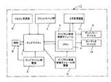
図1は本実施例に適用されるテレビジョン放送受信装置の構成を示した概略ブロック図である。同図に示すようにテレビジョン放送受信装置12は、時計8、リモコン受信部6、フロンスイッチ部7、テレビマイコン1、デジタル放送受信モジュール3、CPU4、2次記憶装置11、テレビマイコン用電源2、デジタル放送受信モジュール用電源5、ディスプレーデバイス9、オーディオデバイス10から構成されている。The best mode for carrying out the invention of the television broadcast receiving apparatus according to the present invention will be described below with reference to preferred embodiments.
FIG. 1 is a schematic block diagram showing the configuration of a television broadcast receiving apparatus applied to this embodiment. As shown in the figure, the
テレビジョン放送受信装置12を制御するコントローラは、テレビ全体を司るテレビマイコン1と、デジタル放送受信モジュール3に装備されたCPU4の2つに分けられる。テレビマイコン1は、リモコン受信部6やフロンスイッチ部7からの信号、つまりユーザからの操作に対しテレビの各部分に様々な制御を行う。特にリモコン受信部6からの電源の信号を受けられるようにするため、テレビマイコン用電源2は常にテレビマイコンに電源を供給する。つまりテレビマイコンはテレビジョン放送受信装置12をコンセントに接続すると同時に動作をはじめる。 The controller that controls the
一方、デジタル放送受信モジュール3には専用のCPU4が搭載されている。このCPU4は、テレビマイコン1からの指令を受け、デジタル放送受信モジュール3の制御を行うと共に、EPGデータ取得等のデジタル放送受信に必要な動作をテレビマイコン1とは独立に行う。また通常テレビが映っていない場合、デジタル放送受信モジュール3は電源を入れておく必要はなく、デジタル放送受信モジュール用電源5はテレビマイコン1からON/OFF制御が行われる。 On the other hand, a dedicated CPU 4 is mounted on the digital broadcast receiving module 3. The CPU 4 receives a command from the television microcomputer 1 and controls the digital broadcast receiving module 3 and performs operations necessary for digital broadcast reception such as EPG data acquisition independently of the television microcomputer 1. When the television is not normally displayed, the digital broadcast receiving module 3 does not need to be turned on, and the digital broadcast receiving
今、ユーザがデジタル放送を視聴するために、テレビジョン放送受信装置12の電源を入れたとする(ここで「電源を入れる」とはリモコンで電源をONすることを指す)。テレビマイコン1はリモコン受信部6からの信号で電源がONされたことを察知し、ディスプレーデバイス9やオーディオデバイス10の起動を行うと共に、デジタル放送受信モジュール用電源5をONにしてデジタル信号受信モジュール3の起動を行う。デジタル信号受信モジュール3は電源投入に対応し、デジタル信号受信システムを起動し、受信した画像/音声を出力できるようにする。さらにテレビマイコン1からチャンネル選局などの更なる指令に応じて処理を行う。 Now, it is assumed that the user turns on the power of the television
一方、デジタル放送受信モジュール3もテレビマイコン1と同様に、テレビジョン放送受信装置12をコンセントに接続すると同時に常に電源が入るようなシステム構成としてもよい。この場合、リモコンでテレビの電源ONの指令に対し、テレビマイコン1はデジタル放送受信モジュール3に対して電源投入の処理を行う必要はない。 On the other hand, similarly to the television microcomputer 1, the digital broadcast receiving module 3 may have a system configuration in which the power is always turned on at the same time as the television
図1において、時計8は現在時刻を保持するために使用される。デジタル放送受信を行うテレビジョン放送受信装置12において、現在時刻はデジタル放送を通じて取得できるため、デジタル放送を正常に受信している限り現在時刻は、デジタル放送受信モジュール3からテレビマイコン1が情報を取得し、時計8に時刻設定することで正確な時刻を保持することができる。また、時計8はテレビマイコン用電源2で動作しているため、テレビジョン放送受信装置12の電源を待機状態にしている場合でも通電されている。 In FIG. 1, a clock 8 is used to hold the current time. Since the current time can be obtained through digital broadcasting in the television
図2に電源投入予測時刻取得の概略ブロック図を示し、電源投入予測時刻を取得する動作について説明する。テレビジョン放送受信装置12に電源投入あるいは切断の操作が行われると、現在時刻取得手段100aにより電源投入あるいは切断の時刻を確定する。各々の時刻は、受信装置電源投入時刻記録手段100b及び受信装置電源切断時刻記録手段100cにより電源投入時刻予測手段に供給される。ユーザがテレビジョン放送受信装置12を視聴するたびにこれらの動作を行い電源投入予測時刻が算出される。電源投入予測時刻が算出されると、この時刻を基にデジタル放送受信モジュール自動電源投入手段100fにより自動的にデジタル放送受信モジュール3の電源を投入する。受信装置電源投入確認手段100eは、所定時間経過を現在時刻取得手段100aにより取得して、テレビジョン放送受信装置12に電源投入の操作が行われていない場合は、デジタル放送受信モジュール自動電源切断手段100gにより自動的にデジタル放送受信モジュール3の電源を切断させる。 FIG. 2 shows a schematic block diagram of obtaining the predicted power-on time, and the operation for obtaining the predicted power-on time will be described. When the
以下、さらに詳細に電源投入予測時間取得、及び取得後の制御について説明する。
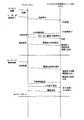
まず、図3のシーケンス図を用いて、通常ユーザが電源を投入する場合(電源投入予測時間取得)の動作について説明する。ユーザがテレビジョン放送受信装置12の電源スイッチをONすると、リモコン受信部6あるいはフロントスイッチ部7から電源投入の信号を受けたテレビマイコン1は、デジタル放送受信モジュール用電源5をONすることで、デジタル方送受信モジュール3の電源を投入すると共に、時計8から時刻を取得する。取得した時刻情報は、デジタル信号受信モジュール3のデジタル放送受信システムが定常動作をはじめた後、デジタル信号受信モジュール3内のCPU4に供給され、さらにデジタル信号受信モジュール3と接続されている2次記憶装置11に保存される。Hereinafter, the acquisition of the power-on estimated time and the control after the acquisition will be described in more detail.
First, the operation when the normal user turns on the power (acquisition of predicted power-on time) will be described using the sequence diagram of FIG. When the user turns on the power switch of the
また、ユーザがテレビジョン放送受信装置12の電源をOFFすると、リモコン受信部6あるいはフロントスイッチ部7から電源切断の信号をうけたテレビマイコン1は、時計8から時刻を取得する。取得した時刻は、デジタル信号受信モジュール3内のCPU4に供給される。CPU4では2次記憶装置11に記録された電源投入時刻と、供給された電源切断時刻から、次にユーザが電源を投入するであろう時刻を予測する。予測した時刻はテレビマイコン1に供給された後、テレビマイコン1は、デジタル信号受信モジュール3の電源をOFFする。 When the user turns off the power of the
次に、図4のシーケンス図を用いて、テレビジョン放送受信装置12が電源投入予測時刻に電源を投入する場合の動作について説明する。テレビマイコン1は、電源投入予測時刻になると、デジタル信号受信モジュール3の電源を投入する処理を行うため、テレビジョン放送受信装置12の電源が既に投入されているかどうかをチェックする。電源未投入の場合は、デジタル放送受信モジュール3の電源を投入する。テレビジョン放送受信装置12の電源が投入された場合には、テレビマイコン1はデジタル放送受信モジュール3の電源が既に投入されているかどうかを調べる。既に投入されている場合は、デジタル放送受信モジュール3の電源を投入する過程をスキップする。 Next, the operation when the television
また、テレビマイコン1は、電源投入予測時刻よりある一定以上の時間が経過してもテレビジョン放送受信装置12の電源が入れられることがなかった場合、デジタル信号受信モジュール3に、電源投入がなかったことを通知して、次の電源投入予測時刻を要求する。デジタル信号受信モジュール3はテレビマイコン1に予測時刻を通知する。電源投入予測時刻を通知されたテレビマイコンはデジタル信号受信モジュール3の電源を切断する。 In addition, the television microcomputer 1 does not turn on the digital signal receiving module 3 if the television
次に、図5に操作履歴の一例をあげ、これを基に時刻予測手法を説明する。テレビマイコン1より与えられた現在時刻(電源切断時刻)から24時間戻した時刻から一番近い未来の時刻を求める。その時刻から24時間進めた時間が、電源投入予測時刻となる。現在時刻は、7月9日22時32分なので、24時間戻した時刻から一番近い未来は、7月9日6時11分となる。これから、電源投入予測時刻となるのは7月10日6時11分である。 Next, FIG. 5 shows an example of the operation history, and the time prediction method will be described based on this. The nearest future time is obtained from the time returned from the current time (power-off time) given by the television microcomputer 1 for 24 hours. The time advanced by 24 hours from that time is the predicted power-on time. Since the current time is 22:32 on July 9, the closest future from the time returned by 24 hours is 6:11 on July 9. From now on, the predicted power-on time is 6:11 on July 10th.
また別方法として、現在時刻から、48時間・72時間戻した時刻から一番近い未来をもとめ、24時間戻した時刻から一番近い未来の時間とともに、時刻だけ抜き出す。その時刻の内一番早い時刻で24時間以内のものが電源投入予想時刻とする方法とする。この場合、予想時刻は、7月10日5時48分となる。
予測手段は、上述の方法に限らず他の方法、例えば曜日の情報を優先して用いる構成としてもよい。また、何通りか用意しておきユーザが選択可能である構成としてもよい。
さらに、予測に失敗した場合には、予測に成功した場合の情報に基づいて予測手段手法を調整するように構成してもよい。As another method, the nearest future is obtained from the time returned by 48 hours and 72 hours from the current time, and only the time is extracted together with the nearest future time from the time returned by 24 hours. The earliest time within that time and within 24 hours is assumed to be the expected power-on time. In this case, the expected time is 5:48 on July 10.
The predicting means is not limited to the above-described method, and may be configured to use other methods, for example, the day information with priority. Moreover, it is good also as a structure which several prepares and a user can select.
Furthermore, when prediction fails, you may comprise so that a prediction means method may be adjusted based on the information when prediction is successful.
デジタル信号受信モジュール3に電源を投入する時刻であるが、電源投入予測時刻よりさらに若干電源投入時刻を早めて、電源投入予測時刻までにデジタル放送のEPGなどのデータを取得するように構成してもよい。この場合、デジタル放送受信モジュール3は起動直後から電源投入予測時刻までの間にデジタル放送の各チャンネルからデータを収集することができるのでさらに利便性が向上する。 Although it is the time to turn on the digital signal receiving module 3, the power-on time is slightly earlier than the predicted power-on time, and data such as EPG of digital broadcasting is acquired by the predicted power-on time. Also good. In this case, since the digital broadcast receiving module 3 can collect data from each channel of the digital broadcast between immediately after activation and the predicted power-on time, the convenience is further improved.
デジタル信号受信モジュール3は、テレビジョン放送受信装置12に一体の構成でも、別筐体で構成されるいわゆるセットトップボックスとして構成してもよい。 The digital signal receiving module 3 may be configured integrally with the television
上述のように本発明の目的は、消費電力を常時入電の状態より下げつつ、電源スイッチを押したときにデジタル放送受信モジュールの電源が投入される時に発生する待ち時間をできるだけ削減することにある。現在のLinuxOSでは起動時間の短縮には限度が存在するため、リモコンで電源を投入してからデジタル放送受信モジュールの電源を投入したのでは電源投入からテレビジョン放送受信装置に番組が表示されるまでのタイムラグがユーザに知覚されてしまう。そのため、電源投入予測時刻を算出して、ユーザが電源スイッチを押す前にデジタル放送受信モジュールの電源が投入される手段を提供している。
従って、Linux以外のOSに用いてもよい。また、テレビジョン放送受信装置に限らずユーザが使用する時刻に規則性が見られる他の機器に対して用いてもよい。As described above, an object of the present invention is to reduce as much as possible the waiting time that occurs when the power of the digital broadcast receiving module is turned on when the power switch is pressed while lowering the power consumption from the constant power-on state. . Since there is a limit to shortening the startup time in the current Linux OS, if the digital broadcast receiving module is turned on after turning on the power with the remote control, the program is displayed from the power on to the television broadcast receiving apparatus. Is perceived by the user. Therefore, a means is provided for calculating the power-on estimated time and turning on the digital broadcast receiving module before the user presses the power switch.
Therefore, it may be used for an OS other than Linux. Moreover, you may use not only for a television broadcast receiving apparatus but with respect to the other apparatus with which regularity is seen at the time which a user uses.
1…テレビマイコン
2…テレビマイコン用電源
3…デジタル放送受信モジュール
4…CPU
5…デジタル放送受信モジュール用電源
6…リモコン受信部
7…フロンスイッチ部
8…時計
9…ディスプレーデバイス
10…オーディオデバイス
11…2次記憶装置
12…テレビジョン放送受信装置
1 ... TV microcomputer 2 ... TV microcomputer power supply 3 ... Digital broadcast receiving module 4 ... CPU
5 ... Power source for digital broadcast receiving module 6 ... Remote control receiving unit 7 ... Fron switch unit 8 ... Clock 9 ...
Claims (1)
Translated fromJapanese前記テレビジョン放送受信装置内に有する時刻発生手段より時刻情報を検出する時刻検出手段と、
前記時刻検出手段より得られた時刻情報とユーザによる前記テレビジョン放送受信装置本体の電源部の電源投入操作情報とにより電源投入操作毎の時刻を取得する電源投入時刻取得手段と、
前記取得された電源投入時刻を累積記憶するための記憶手段と、
前記記憶手段に記憶された前記電源投入時刻から前記ユーザの視聴時刻傾向を算出し次回の電源投入時刻を予測する電源投入時刻予測手段と、
を有し、前記電源投入時刻予測手段により予測した時刻に前記テレビジョン放送受信装置本体の電源部のオン・オフにかかわらず前記番組情報取得手段の電源部をオン状態に制御するようにしたことを特徴とするテレビジョン放送受信装置。
A television broadcast receiver having a program information acquisition unit for receiving a digital broadcast to which program information is added and acquiring the program information, a power source unit of the program information acquisition unit, and a power source unit of the apparatus body,
Time detection means for detecting time information from time generation means included in the television broadcast receiver;
A power-on time acquisition unit that acquires a time for each power-on operation based on the time information obtained from the time detection unit and the power-on operation information of the power unit of the television broadcast receiver main body by the user;
Storage means for accumulatively storing the acquired power-on time;
A power-on time predicting means for calculating a viewing time trend of the user from the power-on time stored in the storage means and predicting a next power-on time;
The power supply unit of the program information acquisition unit is controlled to be turned on regardless of whether the power supply unit of the television broadcast receiving apparatus body is on or off at the time predicted by the power-on time prediction unit. A television broadcast receiver characterized by the above.
Priority Applications (1)
| Application Number | Priority Date | Filing Date | Title |
|---|---|---|---|
| JP2003429329AJP2005191815A (en) | 2003-12-25 | 2003-12-25 | Television broadcast receiving device |
Applications Claiming Priority (1)
| Application Number | Priority Date | Filing Date | Title |
|---|---|---|---|
| JP2003429329AJP2005191815A (en) | 2003-12-25 | 2003-12-25 | Television broadcast receiving device |
Publications (1)
| Publication Number | Publication Date |
|---|---|
| JP2005191815Atrue JP2005191815A (en) | 2005-07-14 |
Family
ID=34788031
Family Applications (1)
| Application Number | Title | Priority Date | Filing Date |
|---|---|---|---|
| JP2003429329APendingJP2005191815A (en) | 2003-12-25 | 2003-12-25 | Television broadcast receiving device |
Country Status (1)
| Country | Link |
|---|---|
| JP (1) | JP2005191815A (en) |
Cited By (22)
| Publication number | Priority date | Publication date | Assignee | Title |
|---|---|---|---|---|
| JP2007042191A (en)* | 2005-08-02 | 2007-02-15 | Sony Corp | Electronic apparatus, and starting method of electronic apparatus |
| WO2007026532A1 (en)* | 2005-08-31 | 2007-03-08 | Sharp Kabushiki Kaisha | Information processing device, television broadcast receiver and television broadcast recording/reproducing device |
| WO2007026615A1 (en)* | 2005-08-31 | 2007-03-08 | Sharp Kabushiki Kaisha | Information processing device, telecasting receiver, and telecasting recorder/reproducer |
| JP2007133621A (en)* | 2005-11-10 | 2007-05-31 | Sony Corp | Electronic equipment, control method for electronic equipment, program for control method for electronic equipment, and recording medium recording program for control method for electronic equipment |
| JP2007150978A (en)* | 2005-11-30 | 2007-06-14 | Toshiba Corp | Broadcast receiver |
| JP2007166575A (en)* | 2005-12-15 | 2007-06-28 | Tatung Co | Liquid crystal television apparatus with double stage power supply control |
| JP2007214949A (en)* | 2006-02-10 | 2007-08-23 | Sharp Corp | Video display device |
| JP2007214983A (en)* | 2006-02-10 | 2007-08-23 | Sharp Corp | Video display device with quick start mode |
| JP2008022115A (en)* | 2006-07-11 | 2008-01-31 | Sharp Corp | Digital television receiver |
| EP1892954A1 (en)* | 2006-08-25 | 2008-02-27 | Hitachi, Ltd. | Broadcast receiving apparatus and starting method thereof |
| JP2008131360A (en)* | 2006-11-21 | 2008-06-05 | Sharp Corp | Device with standby mode and digital television device |
| JP2008205882A (en)* | 2007-02-21 | 2008-09-04 | Sharp Corp | Electronic device startup mode setting method and electronic device |
| WO2009082500A1 (en)* | 2007-12-25 | 2009-07-02 | Shenzhen Tcl New Technology Ltd | System and method for power management in an electronic device |
| JP2010268361A (en)* | 2009-05-18 | 2010-11-25 | Mitsubishi Electric Corp | Power control device |
| JP2011050088A (en)* | 2010-10-21 | 2011-03-10 | Hitachi Ltd | Display device, digital broadcast receiver, and method of controlling start of the same |
| WO2011064925A1 (en)* | 2009-11-26 | 2011-06-03 | パナソニック株式会社 | Content output control device and content output control method |
| JP2011147135A (en)* | 2011-01-26 | 2011-07-28 | Hitachi Ltd | Display device, and method of controlling start-up of digital broadcast receiver |
| JP2011211743A (en)* | 2011-06-06 | 2011-10-20 | Hitachi Ltd | Display device |
| US8115875B2 (en) | 2006-05-19 | 2012-02-14 | Sony Corporation | Image display device and method of controlling the same |
| JP2012049749A (en)* | 2010-08-25 | 2012-03-08 | Sony Corp | Information processor and information processing method |
| JP2012151902A (en)* | 2012-04-27 | 2012-08-09 | Hitachi Ltd | Display device |
| WO2012169038A1 (en)* | 2011-06-09 | 2012-12-13 | Necディスプレイソリューションズ株式会社 | Electronic apparatus, power supply operation log recording method, and recording medium |
- 2003
- 2003-12-25JPJP2003429329Apatent/JP2005191815A/enactivePending
Cited By (30)
| Publication number | Priority date | Publication date | Assignee | Title |
|---|---|---|---|---|
| JP2007042191A (en)* | 2005-08-02 | 2007-02-15 | Sony Corp | Electronic apparatus, and starting method of electronic apparatus |
| JPWO2007026615A1 (en)* | 2005-08-31 | 2009-03-05 | シャープ株式会社 | Information processing apparatus, television broadcast receiver, and television broadcast recording / reproducing device |
| WO2007026532A1 (en)* | 2005-08-31 | 2007-03-08 | Sharp Kabushiki Kaisha | Information processing device, television broadcast receiver and television broadcast recording/reproducing device |
| WO2007026615A1 (en)* | 2005-08-31 | 2007-03-08 | Sharp Kabushiki Kaisha | Information processing device, telecasting receiver, and telecasting recorder/reproducer |
| JPWO2007026532A1 (en)* | 2005-08-31 | 2009-03-26 | シャープ株式会社 | Information processing apparatus, television broadcast receiver, and television broadcast recording / reproducing device |
| JP2007133621A (en)* | 2005-11-10 | 2007-05-31 | Sony Corp | Electronic equipment, control method for electronic equipment, program for control method for electronic equipment, and recording medium recording program for control method for electronic equipment |
| JP2007150978A (en)* | 2005-11-30 | 2007-06-14 | Toshiba Corp | Broadcast receiver |
| JP2007166575A (en)* | 2005-12-15 | 2007-06-28 | Tatung Co | Liquid crystal television apparatus with double stage power supply control |
| JP2007214983A (en)* | 2006-02-10 | 2007-08-23 | Sharp Corp | Video display device with quick start mode |
| JP2007214949A (en)* | 2006-02-10 | 2007-08-23 | Sharp Corp | Video display device |
| US8115875B2 (en) | 2006-05-19 | 2012-02-14 | Sony Corporation | Image display device and method of controlling the same |
| JP2008022115A (en)* | 2006-07-11 | 2008-01-31 | Sharp Corp | Digital television receiver |
| CN101778227B (en)* | 2006-08-25 | 2013-01-02 | 株式会社日立制作所 | Broadcast receiving apparatus and starting method thereof |
| JP2008054085A (en)* | 2006-08-25 | 2008-03-06 | Hitachi Ltd | Broadcast receiving apparatus and activation method thereof |
| EP1892954A1 (en)* | 2006-08-25 | 2008-02-27 | Hitachi, Ltd. | Broadcast receiving apparatus and starting method thereof |
| US7730507B2 (en) | 2006-08-25 | 2010-06-01 | Hitachi, Ltd. | Broadcast receiving apparatus and starting method thereof |
| CN101778227A (en)* | 2006-08-25 | 2010-07-14 | 株式会社日立制作所 | Broadcast receiving apparatus and starting method thereof |
| JP2008131360A (en)* | 2006-11-21 | 2008-06-05 | Sharp Corp | Device with standby mode and digital television device |
| JP2008205882A (en)* | 2007-02-21 | 2008-09-04 | Sharp Corp | Electronic device startup mode setting method and electronic device |
| WO2009082500A1 (en)* | 2007-12-25 | 2009-07-02 | Shenzhen Tcl New Technology Ltd | System and method for power management in an electronic device |
| US8531611B2 (en) | 2007-12-25 | 2013-09-10 | Shenzhen Tcl New Technology Ltd. | System and method for power management in an electronic device |
| JP2010268361A (en)* | 2009-05-18 | 2010-11-25 | Mitsubishi Electric Corp | Power control device |
| WO2011064925A1 (en)* | 2009-11-26 | 2011-06-03 | パナソニック株式会社 | Content output control device and content output control method |
| US8711090B2 (en) | 2009-11-26 | 2014-04-29 | Panasonic Corporation | Content output control device and content output control method |
| JP2012049749A (en)* | 2010-08-25 | 2012-03-08 | Sony Corp | Information processor and information processing method |
| JP2011050088A (en)* | 2010-10-21 | 2011-03-10 | Hitachi Ltd | Display device, digital broadcast receiver, and method of controlling start of the same |
| JP2011147135A (en)* | 2011-01-26 | 2011-07-28 | Hitachi Ltd | Display device, and method of controlling start-up of digital broadcast receiver |
| JP2011211743A (en)* | 2011-06-06 | 2011-10-20 | Hitachi Ltd | Display device |
| WO2012169038A1 (en)* | 2011-06-09 | 2012-12-13 | Necディスプレイソリューションズ株式会社 | Electronic apparatus, power supply operation log recording method, and recording medium |
| JP2012151902A (en)* | 2012-04-27 | 2012-08-09 | Hitachi Ltd | Display device |
Similar Documents
| Publication | Publication Date | Title |
|---|---|---|
| JP2005191815A (en) | Television broadcast receiving device | |
| US8305249B2 (en) | Systems and methods for controlling power consumption in electronic devices | |
| US8199067B2 (en) | Display apparatus and a control method therefor | |
| CN100484208C (en) | Image display device and method for controlling the same | |
| EP1876527A1 (en) | Method of automatically upgrading broadcast receiving apparatus, and apparatus incorporating the same | |
| JP4927591B2 (en) | Electronic device startup mode setting method and electronic device | |
| JP5003065B2 (en) | PC with TV viewing function | |
| WO2009096140A1 (en) | Digital broadcast receiving device and software download method | |
| JP4609629B2 (en) | External device control apparatus and external device control method | |
| JPWO2009016719A1 (en) | Automatic start setting device, method and program | |
| US8565587B2 (en) | Recording control apparatus and method for controlling recording control apparatus | |
| JP4673238B2 (en) | Recording apparatus and function execution method | |
| JP7491512B2 (en) | Recording reservation device and recording reservation method | |
| JP5094382B2 (en) | Control device, information processing device, and program | |
| JP3734033B2 (en) | Broadcast receiver | |
| JP5269359B2 (en) | Information processing apparatus and output control method | |
| KR100227112B1 (en) | How to control on / off timer function of TV | |
| JP2005101950A (en) | Electronic apparatus, remote controller, operation system for electronic apparatus, and operation method for electronic apparatus | |
| KR100782188B1 (en) | Channel searching device and method of image display device | |
| KR20100092082A (en) | Apparatus for controlling power and method using the apparatus | |
| JP2006352963A (en) | POWER SUPPLY SYSTEM AND ELECTRIC DEVICE HAVING THE POWER SUPPLY SYSTEM | |
| KR100317670B1 (en) | Sleeping mode operating method | |
| JP2008028625A (en) | Television receiver system | |
| JP2005347994A (en) | Timer reservation system and its method | |
| JP2006270539A (en) | Apparatus and method for video recording management, and program |