JP2005190316A - Electronics - Google Patents
ElectronicsDownload PDFInfo
- Publication number
- JP2005190316A JP2005190316AJP2003432834AJP2003432834AJP2005190316AJP 2005190316 AJP2005190316 AJP 2005190316AJP 2003432834 AJP2003432834 AJP 2003432834AJP 2003432834 AJP2003432834 AJP 2003432834AJP 2005190316 AJP2005190316 AJP 2005190316A
- Authority
- JP
- Japan
- Prior art keywords
- fan
- air
- housing
- blowing
- posture
- Prior art date
- Legal status (The legal status is an assumption and is not a legal conclusion. Google has not performed a legal analysis and makes no representation as to the accuracy of the status listed.)
- Pending
Links
Images


Classifications
- H—ELECTRICITY
- H05—ELECTRIC TECHNIQUES NOT OTHERWISE PROVIDED FOR
- H05K—PRINTED CIRCUITS; CASINGS OR CONSTRUCTIONAL DETAILS OF ELECTRIC APPARATUS; MANUFACTURE OF ASSEMBLAGES OF ELECTRICAL COMPONENTS
- H05K7/00—Constructional details common to different types of electric apparatus
- H05K7/20—Modifications to facilitate cooling, ventilating, or heating
- H05K7/20009—Modifications to facilitate cooling, ventilating, or heating using a gaseous coolant in electronic enclosures
- H05K7/20136—Forced ventilation, e.g. by fans
- H05K7/20172—Fan mounting or fan specifications
- G—PHYSICS
- G06—COMPUTING OR CALCULATING; COUNTING
- G06F—ELECTRIC DIGITAL DATA PROCESSING
- G06F1/00—Details not covered by groups G06F3/00 - G06F13/00 and G06F21/00
- G06F1/16—Constructional details or arrangements
- G06F1/20—Cooling means
- G—PHYSICS
- G06—COMPUTING OR CALCULATING; COUNTING
- G06F—ELECTRIC DIGITAL DATA PROCESSING
- G06F2200/00—Indexing scheme relating to G06F1/04 - G06F1/32
- G06F2200/16—Indexing scheme relating to G06F1/16 - G06F1/18
- G06F2200/163—Indexing scheme relating to constructional details of the computer
- G06F2200/1638—Computer housing designed to operate in both desktop and tower orientation
Landscapes
- Engineering & Computer Science (AREA)
- Physics & Mathematics (AREA)
- Theoretical Computer Science (AREA)
- Microelectronics & Electronic Packaging (AREA)
- Human Computer Interaction (AREA)
- General Engineering & Computer Science (AREA)
- General Physics & Mathematics (AREA)
- Thermal Sciences (AREA)
- Cooling Or The Like Of Electrical Apparatus (AREA)
Abstract
Translated fromJapaneseDescription
Translated fromJapanese本発明は、パーソナルコンピュータなどの電子機器に関する。 The present invention relates to an electronic device such as a personal computer.
情報処理装置としては、横置き配置と縦置き配置とが共に可能な筐体と、筐体内に設けられた発熱部と、強制空冷用のファンと、情報処理装置を縦置きに置いたときにこれを感知するセンサと、このセンサの感知によりファンを止める制御回路とを備えたものが知られている。 When the information processing device is placed vertically, the housing that can be placed horizontally and vertically, the heat generating part provided in the housing, the fan for forced air cooling, and the information processing device are placed vertically. There is known a sensor provided with a sensor for detecting this and a control circuit for stopping the fan by the detection of the sensor.
筐体は、吸気通風孔と、排気通風孔と、強制空冷時の空気取り入れ口とを有している。吸気通風孔は、縦置き時に筐体の側面下部となる位置に設けられている。排気通風孔は、縦置き時に筐体の上面となる位置に設けられている。空気取り入れ口は、筐体のファンに臨む部分に設けられている。 The housing has an intake ventilation hole, an exhaust ventilation hole, and an air intake port for forced air cooling. The intake vent hole is provided at a position that becomes the lower part of the side surface of the casing when the apparatus is installed vertically. The exhaust ventilation hole is provided at a position that becomes the upper surface of the housing when the apparatus is installed vertically. The air intake is provided in a portion of the housing facing the fan.
この情報処理装置では、横置きした場合にファンが作動し、強制空冷を行う。このとき、吸気通風孔は排気通風孔として機能する。すなわち、ファンの吸い込み力により空気が空気取り入れ口から入り、筐体内の発熱部を空冷して、排気通風孔及び吸気通風孔から流出する。 In this information processing apparatus, the fan operates when forced horizontally and performs forced air cooling. At this time, the intake vent hole functions as an exhaust vent hole. That is, air enters from the air intake port by the suction force of the fan, air-cools the heat generating part in the housing, and flows out from the exhaust vent hole and the intake vent hole.
また、情報処理装置を縦置きすると、制御回路は、センサからの信号により縦置きであることを感知し、ファンを停止させる。この場合、発熱部により熱せられた空気は上昇するので、下部に位置する吸気通風孔や、空気取り入れ口から入った空気が上昇し、上部に位置する排気通風孔から出る自然対流が発生する。この自然対流により、筐体内の発熱部が空冷される(例えば、特許文献1参照。)。
ところで、情報処理装置のような電子機器の分野においては、文字、音声、画像等の多用な情報を処理する電子部品、例えばCPU(Central Processing Unit)の処理速度の高速化や、多機能化が推進されている。このような電子機器に用いられるCPUは、高集積化や高性能化に伴って動作中の発熱量が増加する傾向にある。そのため、発熱量の大きいCPU等の発熱体を筐体内に収容するに当たっては、筐体内での発熱体の放熱性をさらに高めることが望まれる。 By the way, in the field of electronic equipment such as information processing devices, there is an increase in processing speed and multi-functionality of electronic components, such as CPU (Central Processing Unit), which process a variety of information such as characters, sounds, and images. Has been promoted. CPUs used in such electronic devices tend to increase the amount of heat generated during operation with higher integration and higher performance. Therefore, when housing a heating element such as a CPU that generates a large amount of heat in the casing, it is desirable to further improve the heat dissipation of the heating element in the casing.
しかしながら、特許文献1に記載の技術では、情報処理装置を縦置きした場合に、発熱部(発熱体)の放熱を自然対流により行うため、ファンを用いる強制空冷と比べて放熱効果が小さくなり易い。 However, in the technique described in Patent Document 1, when the information processing apparatus is installed vertically, the heat radiation of the heat generating part (heat generating element) is performed by natural convection, so that the heat radiation effect tends to be small compared to forced air cooling using a fan. .
本発明は、このような事情にもとづいてなされたもので、筐体の姿勢を変えても、発熱体から発せられる熱を筐体の外方に良好に放熱することができる電子機器の提供を目的とする。 The present invention has been made based on such circumstances, and provides an electronic device capable of radiating heat generated from a heating element to the outside of the casing even when the attitude of the casing is changed. Objective.
本発明の1つの形態に係る電子機器は、第1の通気部が設けられた第1の壁、及び、第2の通気部が設けられ、上記第1の壁と交差する方向に延びる第2の壁を有し、上記第1の壁を上方に向ける第1の姿勢と上記第2の壁を上方に向ける第2の姿勢との両方の姿勢で設置可能な筐体と、上記第1の姿勢時に上記第2の通気部側から上記第1の通気部側に向けて送風させる第1の送風方向と、上記第2の姿勢時に上記第1の通気部側から上記第2の通気部側に向けて送風させる第2の送風方向との両方向に送風可能な送風部とを備えている。 An electronic device according to one aspect of the present invention includes a first wall provided with a first ventilation portion and a second wall provided with a second ventilation portion and extending in a direction intersecting the first wall. A housing that can be installed in both a first posture in which the first wall is directed upward and a second posture in which the second wall is directed upward, and the first wall A first air blowing direction that blows air from the second vent portion side toward the first vent portion side in the posture, and the second vent portion side from the first vent portion side in the second posture And a second air blowing section that can blow air in both directions.
本発明によれば、筐体の姿勢を変えても、発熱体から発せられる熱を筐体の外方に良好に放熱することができる電子機器が得られる。 ADVANTAGE OF THE INVENTION According to this invention, even if it changes the attitude | position of a housing | casing, the electronic device which can thermally radiate the heat | fever emitted from a heat generating body to the outward of a housing | casing is obtained.
以下、本発明の第1の実施形態を、電子機器としてのデスクトップ形のパーソナルコンピュータに適用した図1乃至図9に基づいて説明する。 A first embodiment of the present invention will be described below with reference to FIGS. 1 to 9 applied to a desktop personal computer as an electronic apparatus.
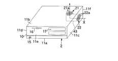
デスクトップ形のパーソナルコンピュータ1は、機器本体としてのコンピュータ本体2、ディスプレイ装置としての液晶ディスプレイ装置3、及びキーボード4等を備えている。液晶ディスプレイ装置3及びキーボード4は、コンピュータ本体2と各々電気的に接続されている。コンピュータ本体2は、偏平な箱形(偏平な直方体状)の筐体10を備えている。図1及び図2は、パーソナルコンピュータ1を、筐体10を横置き姿勢(後述する第1の姿勢)で設置した一例で示している。また、図8は、パーソナルコンピュータ1を、筐体10を縦置き姿勢(後述する第2の姿勢)で設置した一例で示している。 A desktop personal computer 1 includes a computer
詳しくは、筐体10は、横置き姿勢において下側となる底壁11aと、横置き姿勢において上側となる第1の壁としての上壁11bと、上壁11bの一側縁からこの上壁11bと交差する方向、例えば直交下向きに延びる第2の壁としての側壁11cと、上壁11bの他側縁からこの上壁11bと交差する方向、例えば直交下向きに延びる側壁11dと、上壁11bの前縁からこの上壁11bと交差する方向、例えば直交下向きに延びる前壁11eと、上壁11bの後縁からこの上壁11bと交差する方向、例えば直交下向きに延びる後壁11fとを有している。第2の壁としての側壁11cは、例えば、横置き状態において向かって右側に位置している。以下、側壁11cを右側壁と言い、この右側壁11cと対向する側壁11dを左側壁と言う。 Specifically, the
底壁11aの外面は、平坦な搭載面となっている。したがって、筐体10は、上壁11bを上方に向ける第1の姿勢としての横置き姿勢にて、例えば机の天板のような設置面Sに設置可能である。上壁11bの外面は、水平な支持面となっており、この支持面に、例えば液晶ディスプレイ装置3のようなものを置けるようになっている(図1参照)。 The outer surface of the
左側壁11dの外面もまた、平坦な搭載面となっている。したがって、右側壁11cを上方に向ける第2の姿勢としての縦置き姿勢にて、例えば机の天板のような設置面Sに設置可能である(図8参照)。 The outer surface of the
筐体10は、その内部に実装領域を有している。筐体10内には、図2及び図3に示すように、制御部としての制御回路12が収容されている。また、筐体10内には、図示しないが、機能部品としての電源ユニット、フロッピー(登録商標)ディスク駆動装置、ハードディスク駆動装置、CD−ROM駆動装置、及びコネクタ等が収容されている。 The
図2及び図3に示すように、制御回路12は、回路基板13と、この回路基板13に実装された多数の回路部品とを備えている。回路部品には、発熱体としてのCPU14が含まれている。回路基板13は、底壁11aに沿って水平に配置され、筐体10にねじ止めされている。 As shown in FIGS. 2 and 3, the
電源ユニット、フロッピーディスク駆動装置、ハードディスク駆動装置、CD−ROM駆動装置、及びコネクタは、筐体10に支持されているとともに、各々ケーブルを介して制御回路12と電気的に接続されている。 The power supply unit, the floppy disk drive device, the hard disk drive device, the CD-ROM drive device, and the connector are supported by the
図1及び図8に示すように、電源ユニットのON・OFFを行う電源スイッチ15は、前壁11eを介して外方に露出している。そのため、電源スイッチ15を操作することにより、電源ユニットのON・OFFを筐体10の外方から行うことができる。フロッピーディスク駆動装置及びCD−ROM駆動装置は、前壁11e側に寄せて配置されている。前壁11eには、フロッピーディスク駆動装置に連なる第1のディスク挿入部16、及び、CD−ROM駆動装置に連なる第2のディスク挿入部17が設けられている。また、電源コネクタを始めとして、プリンタのような各種の周辺機器を接続するための複数のコネクタは、後壁11fに沿って配置されている。これらコネクタは、後壁11fを介して外方に露出している。そのため、これらコネクタに電源ケーブルや周辺機器に連なるケーブルを接続することができる。 As shown in FIGS. 1 and 8, the
なお、筐体10は、底壁11aを有する基部と、上壁11b、右側壁11c、左側壁11d、前壁11e、及び後壁11fとを有するカバーとにより構成する等し、必要に応じて、実装領域を開放できるように構成することも可能である。 The
上壁11bには、図1乃至図3や、図7乃至図9に示すように、右壁側に寄せて、第1の通気部21が設けられている。第1の通気部21は、通気孔としての複数の小孔21aを有している。ところで、上述のように、上壁11bの上面は、液晶ディスプレイ装置3等を支持する支持面となる。したがって、第1の通気部21は、液晶ディスプレイ装置3を上壁11bの上面に設置した際に、この液晶ディスプレイ装置3により小孔21aが閉塞され難いように、前後方向中央よりも後壁11f側に寄せて設けるのが好ましい。 As shown in FIG. 1 to FIG. 3 and FIG. 7 to FIG. 9, the
一方、右側壁11cには、図1や図7乃至図9に示すように、第2の通気部22が設けられている。第2の通気部22は、通気孔としての複数の小孔22aを有している。第2の通気部22は、第1の通気部21に対応するように、前後方向中央よりも後壁11f側に寄せて設けられている。 On the other hand, as shown in FIGS. 1 and 7 to 9, a
また、図2、図4、及び図5に示すように、コンピュータ本体2は、横置き姿勢と縦置き姿勢とを判別する角度センサ30を備えている。角度センサ30は、筐体10に固定され、制御回路12と電気的に接続されている。角度センサ30としては、例えば、遮蔽部31、発光部32、及び受光部33を備えるフォトインタラプタを用いることができる(図4及び図5参照)。なお、図4及び図5は、角度センサ30を、筐体10を横置き姿勢とした状態で示している。 As shown in FIGS. 2, 4, and 5, the computer
遮蔽部31は、略楕円板状の遮蔽板31aと回転軸31bとを有している。回転軸31bは、前壁11eと略平行に配置されている。回転軸31bは、遮蔽板31aの長軸方向の一端部を貫通している。これにより、遮蔽板31aは、図5に矢印Rで示すように、筐体10が横置き姿勢の時と縦置き姿勢の時とで自重により90°回転する。つまり、遮蔽板31aは、筐体10が横置き姿勢の時には、図5に実線で示す位置となり、筐体10が縦置き姿勢の時には、自重により90°回転して、図5に二点鎖線で示す位置となる。 The shielding
発光部32は、例えば、LED等の光源部32aを有している。発光部32は、筐体10を横置き姿勢とした状態において遮蔽板31aの一方の面と対向するように配置されている。受光部33は、光源部32aから発せられた光を感知する感知部33a、例えば、フォトトランジスタを有している。受光部33は、感知部33aを光源部32aと対向させ、且つ、筐体10を横置き姿勢とした状態において遮蔽板31aの他方の面と対向するように配置されている。すなわち、筐体10を横置き姿勢とした状態において、受光部33は、遮蔽板31aを介して、発光部32と対向している。 The
この角度センサ30は、以下のように作用する。筐体10を横置き姿勢とした場合には、遮蔽板31aは、図5において実線で示す位置に配置される。したがって、光源部32aから発せられた光は遮蔽板31aに遮られ、感知部33aには届かない。一方、筐体10を縦置き姿勢とした場合には、遮蔽板31aは、自重により、図5において二点鎖線で示す位置に移動する。したがって、光源部32aから発せられた光は、遮蔽板31aに遮られることなく、感知部33aに届く。 The
つまり、この角度センサ30では、発光部32の光源部32aから発せられた光が受光部33の感知部33aに感知されるか否かにより、筐体10の姿勢を感知している。なお、角度センサ30は、これに限定されるものではない。 In other words, the
図2及び図3に示すように、筐体10内には、CPU14に熱的に接続されたヒートシンク40と、このヒートシンク40を強制的に冷却するクーリングユニット41とが配置されている。ヒートシンク40は、熱導電率の高い金属で形成されている。ヒートシンク40は、表面積が大きくなるように、複数の放熱フィン(図示せず)を有している。 As shown in FIGS. 2 and 3, a
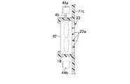
クーリングユニット41は、送風部としてのファン42と、ダクト43とを有している。なお、図中符号44は、ファン42に電力を供給するための電源供給用のコネクタを示している。コネクタ44は、制御回路12と電気的に接続されている。また、図中符号45は、ファン42が備えるケーブルを示している。ファン42が備えるケーブル45の先端部には、電源供給用のコネクタ44に接続されるプラグ(図示せず)が設けられている。 The cooling
ファン42は、筐体10内に、右側壁11cに設けられた第2の通気部22に臨んで配置されている。このファン42は、例えば、右側壁11cの内面に設けられた支持部18にて支持されている。また、このファン42は、制御回路12と電気的に接続されている。なお、ファン42は、上壁11bに設けられた第1の通気部21に臨ませて配置する等してもよい。 The
ダクト43は、図1や図7乃至図9等に最もよく示すように、第1の通気部21と第2の通気部22とを繋ぐように設けられている。また、ダクト43は、図3に示すように、CPU14とヒートシンク40とファン42とを内包している。 The
したがって、CPU14で発せられた熱は、ヒートシンク40に伝わり、空気中に放熱される。温められた空気は、ダクト43中を流通し、第1又は第2の通気部21,22を介して、筐体10の外方に放熱される。 Therefore, the heat generated by the
ところで、CPU14で発せられる熱によって温められた空気を迅速に筐体10の外方に放出させるためには、ファン42を動作させ、ダクト43内の空気を下側から上側に向けて流通させるのが好ましい。 By the way, in order to quickly release the air heated by the heat generated by the
つまり、上壁11bを上方に向ける横置き姿勢の時には、図7に矢印Xで示す方向、すなわち、第2の通気部22側から第1の通気部21側に向けて送風させる第1の送風方向となるように、ダクト43内の空気を強制的に流通させるのが好ましい。一方、右側壁11cを上方に向ける縦置き姿勢の時には、図9に矢印Yで示す方向、すなわち、第1の通気部21側から第2の通気部22側に向けて送風させる第2の送風方向となるように、ダクト43内の空気を強制的に流通させるのが好ましい。 That is, in the horizontal orientation with the
そのため、ファン42としては、第2の通気部22側から第1の通気部21側に向けて送風させる第1の送風方向と、第1の通気部21側から第2の通気部22側に向けて送風させる第2の送風方向との両方向に送風可能なファン42を採用している。このようなファン42としては、上記第1の送風方向に送風する第1の回転方向と、上記第2の送風方向に送風する第2の回転方向との両方向に正逆回転駆動自在なファンが挙げられる。 Therefore, as the
また、このコンピュータ本体2では、制御回路12は、ファン42の回転方向を変化させる制御部を兼ねている。すなわち、ファン42は、角度センサ30で感知された筐体10の姿勢に関する情報に基づいて、制御回路12によりその回転方向が制御される。 In the computer
このコンピュータ本体2では、以下のようにして、CPU14が冷却される(図6参照)。
CPU14で発せられた熱は、ヒートシンク40に伝わり、空気中に放熱される。CPU14近傍の温度が所定の温度以上となると、角度センサ30により、筐体10の姿勢が感知される。In the computer
The heat generated by the
筐体10が横置き姿勢である場合、角度センサ30が、筐体10が横置き姿勢であることを感知して、この情報を制御回路12に伝える。制御回路12は、ダクト43内の空気が上記第1の送風方向(図7に矢印Xで示す方向)に流通するように、ファン42を上記第1の回転方向に回転駆動させる。この場合、第2の通気部22が吸気部となり、第1の通気部21が排気部となる。 When the
つまり、ファン42が上記第1の回転方向に回転駆動すると、第2の通気部22から筐体10外の空気が取り入れられる。ヒートシンク40は、第2の通気部22から取り入れられた外部の空気により冷やされる。ヒートシンク40から空気中に放熱された熱は、自然対流とファン42とにより発せられる風に乗じ、第1の通気部21を介して、筐体10の外部に上方に向けて放出される。 That is, when the
一方、筐体10が縦置き姿勢である場合、角度センサ30が、筐体10が縦置き姿勢であることが感知して、この情報を制御回路12に伝える。制御回路12は、ダクト43内の空気が上記第2の送風方向(図9に矢印Yで示す方向)に流通するように、ファン42を上記第2の回転方向に回転駆動させる。この場合、第1の通気部21が吸気部となり、第2の通気部22が排気部となる。 On the other hand, when the
つまり、ファン42が上記第2の回転方向に回転駆動すると、第1の通気部21から筐体10外の空気が取り入れられる。ヒートシンク40は、第1の通気部21から取り入れられた外部の空気により冷やされる。ヒートシンク40から空気中に放熱された熱は、自然対流とファン42により発せられる風に乗じ、第2の通気部22を介して、筐体10の外部に上方に向けて放出される。 That is, when the
また、このコンピュータ本体2では、CPU14がダクト43内に設けられているため、CPU14で発せられた熱により温められた空気は、ダクト43を流通して筐体10の外方に放熱される。したがって、回路基板13に実装された多数の回路部品や筐体10内に収容された機能部品等は、CPU14で発せられた熱の影響を受け難い。 Further, in the computer
なお、CPU14近傍の温度が所定の温度未満の場合には、ファン42を停止してもよい。CPU14で発せられた熱は、ヒートシンク40に伝わり、空気中に放熱される。このようにして温められた空気は、自然対流にてダクト43中を流通し、第1又は第2の通気部21,22を介して、筐体10の外方に放熱される。 Note that the
以上のように、このパーソナルコンピュータ1によれば、コンピュータ本体2の筐体10が横置き姿勢の場合には、送風部としてのファン42によって強制的に、右側壁11cに設けられた第2の通気部22から上壁11bに設けられた第1の通気部21側に向けて空気を流通させる第1の送風方向に空気の流れを生じさせる。一方、筐体10が縦置き姿勢の場合には、送風部としてのファン42によって強制的に、上壁11bに設けられた第1の通気部21から右側壁11cに設けられた第2の通気部22側に向けて空気を流通させる第2の送風方向に空気の流れを生じさせるようにしている。したがって、筐体10を横置き姿勢としても縦置き姿勢としても、筐体10内の空気を下側から上側に向かって強制的に流通させることができる。したがって、筐体10の姿勢を変えても、CPU14から発せられる熱を筐体10の外方に良好に放熱することができる。 As described above, according to the personal computer 1, when the
また、コンピュータ本体2は、筐体10内に、第1の通気部21と第2の通気部22とを繋ぐダクト43を備えており、CPU14は、ダクト43内に設けられている。そのため、CPU14から空気中に放熱された熱は、ダクト43内において流通する。したがって、回路基板13に実装された多数の回路部品や筐体10内に収容された機能部品等には、CPU14で発せられた熱による影響が与えられ難い。 Further, the computer
さらに、送風部はファン42を有しており、このファン42が上記第1の送風方向に送風する第1の回転方向と、上記第2の送風方向に送風する第2の回転方向との両方向に回転駆動自在とされている。そのため、簡単な構成で、筐体10内(このパーソナルコンピュータ1ではダクト43内)の空気を上記第1及び第2の送風方向の双方向に送風させることができる。 Further, the air blowing section has a
しかも、ファン42は、制御回路12により、筐体10が横置き姿勢の時に上記第1の回転方向に回転駆動するように制御されるとともに、筐体10が縦置き姿勢の時に上記第2の回転方向に回転駆動するように制御される。また、コンピュータ本体2は、筐体10の姿勢を判別する角度センサ30、すなわち、横置き姿勢と縦置き姿勢とを判別する角度センサ30を備えており、制御回路12は、この角度センサ30で感知された情報に基づいて、ファン42の回転方向を制御する。したがって、筐体10が横置きであっても縦置きであっても、パーソナルコンピュータ1を使用するユーザーに何ら手間をかけさせることなく、CPU14より温められた空気を上方に向けて筐体10の外方に排気することができる。 In addition, the
以下、本発明の第2の実施形態を、図10に基づいて説明する。
デスクトップ形のパーソナルコンピュータ1では、一旦、コンピュータ本体2及び液晶ディスプレイ装置3を配置してしまうと、これらの位置をあまり頻繁に変化させないことが多い。そのため、本実施形態のパーソナルコンピュータ1が備えるコンピュータ本体2では、角度センサ30を省略し、ファン42の回転方向を変化させる信号を手動で入力する操作部50を設けている。操作部50としては、ボタン50aを押すことで、ファン42の回転方向を変化させる信号を発するものを用いることができる。Hereinafter, a second embodiment of the present invention will be described with reference to FIG.
In the desktop personal computer 1, once the computer
この操作部50は、筐体10を介して外方に露出するように、筐体10内に設けられている。詳しくは、筐体10の右側壁11cには、第1の通気部21と隣接するように、開口部51が設けられている。この開口部51は、パーソナルコンピュータ1を使用するユーザーの指先が不用意に入り込まない程度の大きさとしている。操作部50は、この開口部51と対向するように、筐体10内に収容されている。つまり、操作部50は、ファン42と隣接して配置されることとなる。操作部50は、制御回路12と電気的に接続されている。なお、他の構成は、図示しない部分を含めて上述した第1の実施形態と同じであるから、重複する説明は図に同符号を付して省略する。 The
このパーソナルコンピュータ1では、コンピュータ本体2及び液晶ディスプレイ装置3を配置する際に、その配置に適したファン42の回転方向となるように操作部50を操作すればよい。すなわち、初期状態において、ファン42が、ダクト43内の空気を上記第1の送風方向に送風する上記第1の回転方向に回転駆動する設定であるとする。コンピュータ本体2を横置き姿勢とする場合には、そのまま使用すればよく、CPU14近傍の温度が所定の温度以上となると、ファン42が上記第1の回転方向に回転する。 In the personal computer 1, when the computer
コンピュータ本体2を縦置き姿勢とする場合には、ペン先のような細長な棒52等を、開口部51を介して筐体10内に差し込むことにより、操作部50のボタン50aを押す(操作する)。操作部50を操作すると、その信号が制御回路12に伝えられ、制御回路12がファン42の回転方向を変化させる制御を行う。これにより、ファン42は、ダクト43内の空気を上記第2の送風方向に送風する上記第2の回転方向に回転駆動されるようになる。以降は、CPU14近傍の温度が所定の温度以上となると、ファン42が上記第2の回転方向に回転する。 In the case where the computer
再度、コンピュータ本体2を縦置き姿勢から横置き姿勢に変化させる場合にも、操作部50を操作する。操作部50を操作すると、その信号が制御回路12に伝えられ、制御回路12がファン42の回転方向を変化させる制御を行う。これにより、ファン42は、ダクト43内の空気を上記第1の送風方向に送風する上記第1の回転方向に回転駆動されるようになる。以降は、CPU14近傍の温度が所定の温度以上となると、ファン42が上記第1の回転方向に回転する。再々度、コンピュータ本体2を横置き姿勢から縦置き姿勢に変化させる場合にも同様である。 The
一般に、角度センサ30は高価であることが多いため、筐体10の姿勢を判別する手段として角度センサ30を採用すると、パーソナルコンピュータ1が高価となり易い。そのため、角度センサ30を省略することで、コンピュータ本体2を安価に製造できる。 In general, since the
また、一般に、コンピュータ本体2及び液晶ディスプレイ装置3を一旦配置すると、これらの位置をあまり頻繁に変化させないことが多い。そのため、ファン42の回転方向を変化させる信号を手動入力としても、ユーザーにさほどの手間を掛けさせない。 In general, once the computer
以上のように、本実施形態のパーソナルコンピュータ1によれば、ファン42の回転方向を変化させる信号を手動で入力する操作部50を設けているため、角度センサ30を省略することができる。したがって、パーソナルコンピュータ1を安価に製造することができる。しかも、ファン42の回転方向を変化させる場合には、操作部50を操作するだけでよい。したがって、ファン42の回転方向を変化させるためにユーザーの手をさほど煩わせることが無い。 As described above, according to the personal computer 1 of the present embodiment, since the
また、このパーソナルコンピュータ1では、操作部50は、筐体10内に設けられている。そのため、パーソナルコンピュータ1のユーザー等が、操作部50に誤って触れてしまうといったことが生じ難い。つまり、このパーソナルコンピュータ1では、操作部50の誤操作を抑制できる。 In the personal computer 1, the
しかも、操作部50は、筐体10を介して外方に露出している。そのため、操作部50が筐体10内に設けられているにもかかわらず、この操作部50を筐体10の外方から操作することが可能である。したがって、このパーソナルコンピュータ1では、操作部50の操作を容易に行うことができる。 In addition, the
以下、本発明の第3の実施形態を、図11に基づいて説明する。
本実施形態のパーソナルコンピュータ1が備えるコンピュータ本体2では、角度センサ30や操作部50を省略し、且つ、一方向に回転駆動自在なファン42を筐体10に着脱自在に設けている。Hereinafter, a third embodiment of the present invention will be described with reference to FIG.
In the computer
詳しくは、ファン42は、上記第1の送風方向(第2の通気部22側から上記第1の通気部21側に向けて空気を流通させる方向)に送風する第1の取付け向きと、上記第2の送風方向(第1の通気部21側から上記第2の通気部22側に向けて空気を流通させる方向)に送風する第2の取付け向きとの両方の取付け向きに取付け可能となるように、右側壁11cの内面に設けられた支持部18に支持されている。つまり、ファン42は、これをひっくり返し、ファン42の羽根の向きを変化させることができるようになっている。 Specifically, the
ところで、ファン42をひっくり返して取付けると、ファン42に設けられたケーブル45の延出方向が変化してしまう。そのため、このコンピュータ本体2は、ファン42の前側と後側とに、ファン42に電力を供給するための2つの電源供給用のコネクタ44a,44bを備えている。このようにすることにより、ケーブル45の長さを変化させることなく、コネクタ44a又はコネクタ44bにケーブル55が備えるプラグを差し込むことができる。 By the way, when the
また、筐体10は、底壁11aを有する基部と、上壁11b、右側壁11c、左側壁11d、前壁11e、及び後壁11fとを有するカバーとにより構成する等している。このようにすることにより、ファン42の向きを変える場合には、実装領域を開放させることができる。なお、他の構成は、図示しない部分を含めて上述した第1の実施形態と同じであるから、重複する説明は図に同符号を付して省略する。 Moreover, the housing | casing 10 is comprised with the base which has the
このパーソナルコンピュータ1では、コンピュータ本体2及び液晶ディスプレイ装置3を配置する際に、ファン42の回転方向がその配置に適した回転方向となるように、このファン42を取付ければよい。すなわち、初期状態において、ファン42が、ダクト43内の空気を上記第1の送風方向に送風するように取付けられていた場合、コンピュータ本体2を横置き姿勢で使用する際には、そのままでよい。 In the personal computer 1, when the computer
コンピュータ本体2を縦置き姿勢とする場合には、筐体10の実装領域を開放させ、プラグをコネクタ44aから外す。そして、ファン42を筐体10から取り外し、裏返してファン42を筐体10に取付ける。そして、プラグをコネクタ45bに差し込み、筐体10を元に戻す。これにより、ファン42は、ダクト43内の空気を上記第2の送風方向に送風するようになる。 When the computer
再度、コンピュータ本体2を縦置き姿勢から横置き姿勢に変化させる場合には、筐体10の実装領域を開放させ、プラグをコネクタ44bから外す。そして、ファン42を筐体10から取り外し、裏返してファン42を筐体10に取付ける。そして、プラグをコネクタ44aに差し込み、筐体10を元に戻す。これにより、ファン42は、ダクト43内の空気を上記第1の送風方向に送風するようになる。再々度、コンピュータ本体2を横置き姿勢から縦置き姿勢に変化させる場合にも同様である。 When the computer
以上のように、このパーソナルコンピュータ1によれば、一方向に回転駆動するファン42を筐体10にひっくり返して取付けることができるようになっている。このようにすることにより、角度センサ30や操作部50を省略できる。したがって、本実施形態のパーソナルコンピュータ1は、角度センサ30及び正逆両回転駆動するファン42を備える第1の実施形態のパーソナルコンピュータ1や、操作部50及び正逆両回転駆動するファン42を備える第2の実施形態のパーソナルコンピュータよりも安価に製造できる。 As described above, according to the personal computer 1, the
なお、上記第1乃至第3の実施形態では、第2の通気部22を設ける第2の壁を、横置き状態において向かって右側壁11cとしているが、第2の壁は、横置き状態において向かって左側壁11dや後壁11fとしても、同様の効果が得られる。 In the first to third embodiments, the second wall provided with the
また、本発明は、上述した実施形態に限定されるものではなく、本発明の要旨を逸脱しない範囲においては種々の態様で実施し得ることは言うまでも無い。 The present invention is not limited to the above-described embodiment, and it goes without saying that the present invention can be implemented in various modes without departing from the gist of the present invention.
1…パーソナルコンピュータ(電子機器)、 2…コンピュータ本体(機器本体)、 10…筐体、 11b…上壁(第1の壁)、 11c…右側壁(第2の壁)、 12…制御回路(制御部)、 14…CPU(発熱体)、 21…第1の通気部、 21a…小孔(通気孔)、 22…第2の通気部、 22a…小孔(通気孔) 30…角度センサ、 42…ファン(送風部)、 43…ダクト、 50…操作部 DESCRIPTION OF SYMBOLS 1 ... Personal computer (electronic device), 2 ... Computer main body (equipment main body), 10 ... Housing | casing, 11b ... Upper wall (1st wall), 11c ... Right side wall (2nd wall), 12 ... Control circuit ( Control part), 14 ... CPU (heating element), 21 ... first ventilation part, 21a ... small hole (ventilation hole), 22 ... second ventilation part, 22a ... small hole (ventilation hole) 30 ... angle sensor, 42 ... Fan (blower part), 43 ... Duct, 50 ... Operation part
Claims (10)
Translated fromJapanese上記第1の姿勢時に上記第2の通気部側から上記第1の通気部側に向けて送風させる第1の送風方向と、上記第2の姿勢時に上記第1の通気部側から上記第2の通気部側に向けて送風させる第2の送風方向との両方向に送風可能な送風部とを備えていることを特徴とする電子機器。A first wall provided with a first ventilation part; and a second wall provided with a second ventilation part and extending in a direction intersecting the first wall. A housing that can be installed in both a first posture facing upward and a second posture facing the second wall upward;
A first air blowing direction for blowing air from the second ventilation portion side toward the first ventilation portion side during the first posture, and the second air flow direction from the first ventilation portion side during the second posture. An electronic device comprising: a blower capable of blowing air in both directions with a second blowing direction that blows air toward the ventilation portion side.
Priority Applications (2)
| Application Number | Priority Date | Filing Date | Title |
|---|---|---|---|
| JP2003432834AJP2005190316A (en) | 2003-12-26 | 2003-12-26 | Electronics |
| US11/011,871US20050164624A1 (en) | 2003-12-26 | 2004-12-14 | Electronic apparatus |
Applications Claiming Priority (1)
| Application Number | Priority Date | Filing Date | Title |
|---|---|---|---|
| JP2003432834AJP2005190316A (en) | 2003-12-26 | 2003-12-26 | Electronics |
Publications (1)
| Publication Number | Publication Date |
|---|---|
| JP2005190316Atrue JP2005190316A (en) | 2005-07-14 |
Family
ID=34790421
Family Applications (1)
| Application Number | Title | Priority Date | Filing Date |
|---|---|---|---|
| JP2003432834APendingJP2005190316A (en) | 2003-12-26 | 2003-12-26 | Electronics |
Country Status (2)
| Country | Link |
|---|---|
| US (1) | US20050164624A1 (en) |
| JP (1) | JP2005190316A (en) |
Cited By (7)
| Publication number | Priority date | Publication date | Assignee | Title |
|---|---|---|---|---|
| JP2010218284A (en)* | 2009-03-17 | 2010-09-30 | Toshiba Tec Corp | Information processor |
| WO2011118430A1 (en)* | 2010-03-25 | 2011-09-29 | 日本電気株式会社 | Information terminal apparatus |
| JP2012083860A (en)* | 2010-10-07 | 2012-04-26 | Toshiba Corp | Electronic apparatus |
| JP2015023206A (en)* | 2013-07-22 | 2015-02-02 | 三菱電機株式会社 | Fan mounting structure |
| JP2015038904A (en)* | 2011-11-18 | 2015-02-26 | 株式会社東芝 | Information processing device and cooling fan control method |
| JP2020126923A (en)* | 2019-02-04 | 2020-08-20 | 富士ゼロックス株式会社 | Air blowing control device and air blowing control program |
| WO2025079835A1 (en)* | 2023-10-12 | 2025-04-17 | 삼성전자 주식회사 | Electronic device and fan driving method using same |
Families Citing this family (11)
| Publication number | Priority date | Publication date | Assignee | Title |
|---|---|---|---|---|
| JP2004348650A (en)* | 2003-05-26 | 2004-12-09 | Toshiba Corp | Electronics |
| JP2005107122A (en)* | 2003-09-30 | 2005-04-21 | Toshiba Corp | Electronics |
| JP4387777B2 (en)* | 2003-11-28 | 2009-12-24 | 株式会社東芝 | Electronics |
| JP2005315157A (en)* | 2004-04-28 | 2005-11-10 | Toshiba Corp | Pump, cooling device and electronic equipment |
| JP4234635B2 (en)* | 2004-04-28 | 2009-03-04 | 株式会社東芝 | Electronics |
| JP2005315158A (en)* | 2004-04-28 | 2005-11-10 | Toshiba Corp | Pumps, cooling devices, and electronics |
| JP2005317797A (en)* | 2004-04-28 | 2005-11-10 | Toshiba Corp | Pumps, electronics and cooling devices |
| JP2005317798A (en)* | 2004-04-28 | 2005-11-10 | Toshiba Corp | Electronics |
| JP4343032B2 (en) | 2004-05-31 | 2009-10-14 | 株式会社東芝 | Cooling structure and projection type image display device |
| JP2006049382A (en)* | 2004-07-30 | 2006-02-16 | Toshiba Corp | Cooling device and electronic equipment |
| DE112010003718B4 (en)* | 2010-01-25 | 2015-06-25 | Hewlett-Packard Development Company, L.P. | Apparatus and method for venting air from a computing device |
Family Cites Families (41)
| Publication number | Priority date | Publication date | Assignee | Title |
|---|---|---|---|---|
| US5268817A (en)* | 1990-04-27 | 1993-12-07 | Kabushiki Kaisha Toshiba | Portable computer with keyboard and having display with coordinate input tablet rotatably mounted to face either toward or away from keyboard when closed over keyboard |
| JP3258198B2 (en)* | 1995-04-28 | 2002-02-18 | 株式会社東芝 | Cooling device for circuit module and portable electronic device having this cooling device |
| US6094180A (en)* | 1996-04-05 | 2000-07-25 | Fakespace, Inc. | Gimbal-mounted virtual reality display system |
| US6005767A (en)* | 1997-11-14 | 1999-12-21 | Vadem | Portable computer having articulated display |
| US20020053421A1 (en)* | 1997-09-10 | 2002-05-09 | Kabushiki Kaisha Toshiba | Heat dissipating structure for electronic apparatus |
| KR100286375B1 (en)* | 1997-10-02 | 2001-04-16 | 윤종용 | Radiator of electronic system and computer system having the same |
| US6464195B1 (en)* | 1997-12-04 | 2002-10-15 | Raymond Hildebrandt | Ergonomic mounting for computer screen displays |
| JP3366244B2 (en)* | 1998-02-04 | 2003-01-14 | 富士通株式会社 | Electronics |
| US6038128A (en)* | 1998-07-14 | 2000-03-14 | Dell U.S.A., L.P. | Computer and computer/docking assembly with improved internal cooling |
| US6282082B1 (en)* | 1998-07-31 | 2001-08-28 | Qubit, Llc | Case for a modular tablet computer system |
| US6377452B1 (en)* | 1998-12-18 | 2002-04-23 | Furukawa Electric Co., Ltd. | Heat pipe hinge structure for electronic device |
| US6483445B1 (en)* | 1998-12-21 | 2002-11-19 | Intel Corporation | Electronic device with hidden keyboard |
| GB2348459B (en)* | 1999-03-27 | 2003-03-19 | Ibm | Lid restraint for portable computer |
| US6231371B1 (en)* | 1999-06-25 | 2001-05-15 | Hewlett-Packard Company | Docking station for multiple devices |
| JP3283853B2 (en)* | 1999-09-17 | 2002-05-20 | 米沢日本電気株式会社 | Docking station |
| US6166907A (en)* | 1999-11-26 | 2000-12-26 | Chien; Chuan-Fu | CPU cooling system |
| US6196850B1 (en)* | 2000-02-10 | 2001-03-06 | International Business Machines Corporation | Rotatable docking station for an electronic device |
| US6418017B1 (en)* | 2000-03-30 | 2002-07-09 | Hewlett-Packard Company | Heat dissipating chassis member |
| US6437973B1 (en)* | 2000-04-18 | 2002-08-20 | Hewlett-Packard Company | Modular mechanism for movable display |
| US6430038B1 (en)* | 2000-04-18 | 2002-08-06 | Hewlett-Packard Company | Computer with articulated mechanism |
| US6313990B1 (en)* | 2000-05-25 | 2001-11-06 | Kioan Cheon | Cooling apparatus for electronic devices |
| JP3302350B2 (en)* | 2000-06-29 | 2002-07-15 | 株式会社東芝 | Electronics |
| US6296048B1 (en)* | 2000-09-08 | 2001-10-02 | Powerwave Technologies, Inc. | Heat sink assembly |
| JP2002099356A (en)* | 2000-09-21 | 2002-04-05 | Toshiba Corp | Electronic equipment cooling device and electronic equipment |
| US6396687B1 (en)* | 2000-10-13 | 2002-05-28 | Dell Products, L.P. | Rotating portable computer docking station |
| JP3607608B2 (en)* | 2000-12-19 | 2005-01-05 | 株式会社日立製作所 | Liquid cooling system for notebook computers |
| US6717798B2 (en)* | 2001-03-22 | 2004-04-06 | Intel Corporation | Docking digital picture displays |
| US20020141159A1 (en)* | 2001-03-29 | 2002-10-03 | Bloemen James Andrew | Sealed and passively cooled telecommunications customer service terminal |
| FR2827115B1 (en)* | 2001-07-06 | 2003-09-05 | Alstom | BOX FOR POWER CONVERTER |
| TW558611B (en)* | 2001-07-18 | 2003-10-21 | Matsushita Electric Industrial Co Ltd | Small pump, cooling system and portable equipment |
| US6873521B2 (en)* | 2001-07-24 | 2005-03-29 | Hewlett-Packard Development Company, L.P. | Multiple environment foldable computer |
| US6480373B1 (en)* | 2001-07-24 | 2002-11-12 | Compaq Information Technologies Group, L.P. | Multifunctional foldable computer |
| JP4512296B2 (en)* | 2001-08-22 | 2010-07-28 | 株式会社日立製作所 | Liquid cooling system for portable information processing equipment |
| JP2003078270A (en)* | 2001-09-07 | 2003-03-14 | Hitachi Ltd | Electronic equipment |
| JP3946018B2 (en)* | 2001-09-18 | 2007-07-18 | 株式会社日立製作所 | Liquid-cooled circuit device |
| JP2003223238A (en)* | 2002-01-28 | 2003-08-08 | Internatl Business Mach Corp <Ibm> | Computer device, monitor unit and support structure of unit facing user |
| US6856506B2 (en)* | 2002-06-19 | 2005-02-15 | Motion Computing | Tablet computing device with three-dimensional docking support |
| US6788530B2 (en)* | 2002-09-24 | 2004-09-07 | International Business Machines Corporation | User friendly computer equipment, monitor unit, and monitor unit setting base |
| JP2004348650A (en)* | 2003-05-26 | 2004-12-09 | Toshiba Corp | Electronics |
| US7035090B2 (en)* | 2003-09-04 | 2006-04-25 | Kabushiki Kaisha Toshiba | Interlocking mechanism for a display |
| JP2005107122A (en)* | 2003-09-30 | 2005-04-21 | Toshiba Corp | Electronics |
- 2003
- 2003-12-26JPJP2003432834Apatent/JP2005190316A/enactivePending
- 2004
- 2004-12-14USUS11/011,871patent/US20050164624A1/ennot_activeAbandoned
Cited By (9)
| Publication number | Priority date | Publication date | Assignee | Title |
|---|---|---|---|---|
| JP2010218284A (en)* | 2009-03-17 | 2010-09-30 | Toshiba Tec Corp | Information processor |
| WO2011118430A1 (en)* | 2010-03-25 | 2011-09-29 | 日本電気株式会社 | Information terminal apparatus |
| JP2011204907A (en)* | 2010-03-25 | 2011-10-13 | Nec Corp | Information terminal apparatus |
| JP2012083860A (en)* | 2010-10-07 | 2012-04-26 | Toshiba Corp | Electronic apparatus |
| JP2015038904A (en)* | 2011-11-18 | 2015-02-26 | 株式会社東芝 | Information processing device and cooling fan control method |
| JP2015023206A (en)* | 2013-07-22 | 2015-02-02 | 三菱電機株式会社 | Fan mounting structure |
| JP2020126923A (en)* | 2019-02-04 | 2020-08-20 | 富士ゼロックス株式会社 | Air blowing control device and air blowing control program |
| JP7318222B2 (en) | 2019-02-04 | 2023-08-01 | 富士フイルムビジネスイノベーション株式会社 | Air blower control device and air blower control program |
| WO2025079835A1 (en)* | 2023-10-12 | 2025-04-17 | 삼성전자 주식회사 | Electronic device and fan driving method using same |
Also Published As
| Publication number | Publication date |
|---|---|
| US20050164624A1 (en) | 2005-07-28 |
Similar Documents
| Publication | Publication Date | Title |
|---|---|---|
| JP2005190316A (en) | Electronics | |
| JP3973864B2 (en) | Printed circuit board unit with cooling device and electronic device | |
| JP2007149007A (en) | Electronics | |
| JP4554503B2 (en) | Heat dissipation device and electronic device | |
| US10747277B2 (en) | Laptop computer with integral cooling | |
| JP4843724B1 (en) | Electronics | |
| US20080024979A1 (en) | Airflow direction controlling apparatus | |
| JP2001306186A (en) | Docking device for portable computer and its docking structure | |
| JP2002366259A (en) | Portable information processing device | |
| US20040130869A1 (en) | Heat dissipation from a hand-held portable computer | |
| US9884397B2 (en) | Control console for a numerically controlled machine tool | |
| EP2921932A2 (en) | Heat dissipating system using fans | |
| JP2006049382A (en) | Cooling device and electronic equipment | |
| JP2019091884A (en) | Electronic apparatus | |
| JP2001318738A (en) | Electronic equipment | |
| JP3911525B2 (en) | Heat dissipation mechanism and electronic device having the heat dissipation mechanism | |
| US7800899B2 (en) | Information processing apparatus | |
| JP2006003928A (en) | PC cooling system | |
| JP6094318B2 (en) | Information processing apparatus and support apparatus | |
| JP2005086006A (en) | Electronic equipment | |
| JP4171028B2 (en) | Electronics | |
| JP4123594B2 (en) | Cooling structure for information equipment | |
| KR200397136Y1 (en) | Cooling apparatus for a note book computer | |
| JP2002353677A (en) | Heat dissipating structure of apparatus equipped with heating element | |
| JP4588741B2 (en) | Printed circuit board unit with cooling device and electronic device |