JP2005189332A - Optical connector, optical fiber with connector, optical fiber connecting apparatus and method for connecting optical fiber - Google Patents
Optical connector, optical fiber with connector, optical fiber connecting apparatus and method for connecting optical fiberDownload PDFInfo
- Publication number
- JP2005189332A JP2005189332AJP2003428071AJP2003428071AJP2005189332AJP 2005189332 AJP2005189332 AJP 2005189332AJP 2003428071 AJP2003428071 AJP 2003428071AJP 2003428071 AJP2003428071 AJP 2003428071AJP 2005189332 AJP2005189332 AJP 2005189332A
- Authority
- JP
- Japan
- Prior art keywords
- optical fiber
- ferrule
- connector
- optical
- end surface
- Prior art date
- Legal status (The legal status is an assumption and is not a legal conclusion. Google has not performed a legal analysis and makes no representation as to the accuracy of the status listed.)
- Pending
Links
- 239000013307optical fiberSubstances0.000titleclaimsabstractdescription327
- 230000003287optical effectEffects0.000titleclaimsabstractdescription222
- 238000000034methodMethods0.000titleclaimsdescription12
- 238000005452bendingMethods0.000claimsdescription30
- 230000013011matingEffects0.000claimsdescription10
- 230000005540biological transmissionEffects0.000abstractdescription21
- 238000011109contaminationMethods0.000abstract1
- 230000002093peripheral effectEffects0.000description30
- 238000003780insertionMethods0.000description20
- 230000037431insertionEffects0.000description20
- 230000006835compressionEffects0.000description13
- 238000007906compressionMethods0.000description13
- 238000010276constructionMethods0.000description12
- 239000011347resinSubstances0.000description11
- 229920005989resinPolymers0.000description11
- 239000000835fiberSubstances0.000description10
- 239000000853adhesiveSubstances0.000description9
- 230000001070adhesive effectEffects0.000description9
- 230000000903blocking effectEffects0.000description9
- 210000000078clawAnatomy0.000description8
- 238000000576coating methodMethods0.000description7
- 230000000694effectsEffects0.000description7
- 239000000463materialSubstances0.000description7
- 239000000758substrateSubstances0.000description7
- 230000003373anti-fouling effectEffects0.000description6
- 239000011248coating agentSubstances0.000description6
- 239000000428dustSubstances0.000description6
- 229910052751metalInorganic materials0.000description6
- 239000002184metalSubstances0.000description6
- 238000003825pressingMethods0.000description4
- 238000013459approachMethods0.000description3
- 238000005516engineering processMethods0.000description3
- 238000004140cleaningMethods0.000description2
- 238000009434installationMethods0.000description2
- 238000005498polishingMethods0.000description2
- 229910052782aluminiumInorganic materials0.000description1
- XAGFODPZIPBFFR-UHFFFAOYSA-NaluminiumChemical compound[Al]XAGFODPZIPBFFR-UHFFFAOYSA-N0.000description1
- 230000037237body shapeEffects0.000description1
- 239000000919ceramicSubstances0.000description1
- 238000003776cleavage reactionMethods0.000description1
- 238000004891communicationMethods0.000description1
- 230000000052comparative effectEffects0.000description1
- 125000004122cyclic groupChemical group0.000description1
- 230000002542deteriorative effectEffects0.000description1
- 238000010586diagramMethods0.000description1
- 230000005489elastic deformationEffects0.000description1
- 238000009429electrical wiringMethods0.000description1
- 230000001747exhibiting effectEffects0.000description1
- 238000012423maintenanceMethods0.000description1
- NJPPVKZQTLUDBO-UHFFFAOYSA-NnovaluronChemical compoundC1=C(Cl)C(OC(F)(F)C(OC(F)(F)F)F)=CC=C1NC(=O)NC(=O)C1=C(F)C=CC=C1FNJPPVKZQTLUDBO-UHFFFAOYSA-N0.000description1
- 238000012545processingMethods0.000description1
- 230000007017scissionEffects0.000description1
- 229920001169thermoplasticPolymers0.000description1
- 229920001187thermosetting polymerPolymers0.000description1
- 239000004416thermosoftening plasticSubstances0.000description1
Images


Classifications
- G—PHYSICS
- G02—OPTICS
- G02B—OPTICAL ELEMENTS, SYSTEMS OR APPARATUS
- G02B6/00—Light guides; Structural details of arrangements comprising light guides and other optical elements, e.g. couplings
- G02B6/24—Coupling light guides
- G02B6/36—Mechanical coupling means
- G02B6/38—Mechanical coupling means having fibre to fibre mating means
- G02B6/3807—Dismountable connectors, i.e. comprising plugs
- G02B6/3873—Connectors using guide surfaces for aligning ferrule ends, e.g. tubes, sleeves, V-grooves, rods, pins, balls
- G02B6/3874—Connectors using guide surfaces for aligning ferrule ends, e.g. tubes, sleeves, V-grooves, rods, pins, balls using tubes, sleeves to align ferrules
- G—PHYSICS
- G02—OPTICS
- G02B—OPTICAL ELEMENTS, SYSTEMS OR APPARATUS
- G02B6/00—Light guides; Structural details of arrangements comprising light guides and other optical elements, e.g. couplings
- G02B6/24—Coupling light guides
- G02B6/36—Mechanical coupling means
- G—PHYSICS
- G02—OPTICS
- G02B—OPTICAL ELEMENTS, SYSTEMS OR APPARATUS
- G02B6/00—Light guides; Structural details of arrangements comprising light guides and other optical elements, e.g. couplings
- G02B6/24—Coupling light guides
- G02B6/36—Mechanical coupling means
- G02B6/38—Mechanical coupling means having fibre to fibre mating means
- G02B6/3807—Dismountable connectors, i.e. comprising plugs
- G02B6/381—Dismountable connectors, i.e. comprising plugs of the ferrule type, e.g. fibre ends embedded in ferrules, connecting a pair of fibres
- G02B6/3825—Dismountable connectors, i.e. comprising plugs of the ferrule type, e.g. fibre ends embedded in ferrules, connecting a pair of fibres with an intermediate part, e.g. adapter, receptacle, linking two plugs
- G—PHYSICS
- G02—OPTICS
- G02B—OPTICAL ELEMENTS, SYSTEMS OR APPARATUS
- G02B6/00—Light guides; Structural details of arrangements comprising light guides and other optical elements, e.g. couplings
- G02B6/24—Coupling light guides
- G02B6/36—Mechanical coupling means
- G02B6/38—Mechanical coupling means having fibre to fibre mating means
- G02B6/3807—Dismountable connectors, i.e. comprising plugs
- G02B6/3833—Details of mounting fibres in ferrules; Assembly methods; Manufacture
- G02B6/3855—Details of mounting fibres in ferrules; Assembly methods; Manufacture characterised by the method of anchoring or fixing the fibre within the ferrule
- G—PHYSICS
- G02—OPTICS
- G02B—OPTICAL ELEMENTS, SYSTEMS OR APPARATUS
- G02B6/00—Light guides; Structural details of arrangements comprising light guides and other optical elements, e.g. couplings
- G02B6/24—Coupling light guides
- G02B6/36—Mechanical coupling means
- G02B6/38—Mechanical coupling means having fibre to fibre mating means
- G02B6/3807—Dismountable connectors, i.e. comprising plugs
- G02B6/3887—Anchoring optical cables to connector housings, e.g. strain relief features
- G02B6/38875—Protection from bending or twisting
- G—PHYSICS
- G02—OPTICS
- G02B—OPTICAL ELEMENTS, SYSTEMS OR APPARATUS
- G02B6/00—Light guides; Structural details of arrangements comprising light guides and other optical elements, e.g. couplings
- G02B6/24—Coupling light guides
- G02B6/36—Mechanical coupling means
- G02B6/38—Mechanical coupling means having fibre to fibre mating means
- G02B6/3807—Dismountable connectors, i.e. comprising plugs
- G02B6/381—Dismountable connectors, i.e. comprising plugs of the ferrule type, e.g. fibre ends embedded in ferrules, connecting a pair of fibres
- G02B6/3818—Dismountable connectors, i.e. comprising plugs of the ferrule type, e.g. fibre ends embedded in ferrules, connecting a pair of fibres of a low-reflection-loss type
- G02B6/3821—Dismountable connectors, i.e. comprising plugs of the ferrule type, e.g. fibre ends embedded in ferrules, connecting a pair of fibres of a low-reflection-loss type with axial spring biasing or loading means
- G—PHYSICS
- G02—OPTICS
- G02B—OPTICAL ELEMENTS, SYSTEMS OR APPARATUS
- G02B6/00—Light guides; Structural details of arrangements comprising light guides and other optical elements, e.g. couplings
- G02B6/24—Coupling light guides
- G02B6/36—Mechanical coupling means
- G02B6/38—Mechanical coupling means having fibre to fibre mating means
- G02B6/3807—Dismountable connectors, i.e. comprising plugs
- G02B6/381—Dismountable connectors, i.e. comprising plugs of the ferrule type, e.g. fibre ends embedded in ferrules, connecting a pair of fibres
- G02B6/3818—Dismountable connectors, i.e. comprising plugs of the ferrule type, e.g. fibre ends embedded in ferrules, connecting a pair of fibres of a low-reflection-loss type
- G02B6/3822—Dismountable connectors, i.e. comprising plugs of the ferrule type, e.g. fibre ends embedded in ferrules, connecting a pair of fibres of a low-reflection-loss type with beveled fibre ends
- G—PHYSICS
- G02—OPTICS
- G02B—OPTICAL ELEMENTS, SYSTEMS OR APPARATUS
- G02B6/00—Light guides; Structural details of arrangements comprising light guides and other optical elements, e.g. couplings
- G02B6/24—Coupling light guides
- G02B6/36—Mechanical coupling means
- G02B6/38—Mechanical coupling means having fibre to fibre mating means
- G02B6/3807—Dismountable connectors, i.e. comprising plugs
- G02B6/3833—Details of mounting fibres in ferrules; Assembly methods; Manufacture
- G02B6/3847—Details of mounting fibres in ferrules; Assembly methods; Manufacture with means preventing fibre end damage, e.g. recessed fibre surfaces
- G02B6/3849—Details of mounting fibres in ferrules; Assembly methods; Manufacture with means preventing fibre end damage, e.g. recessed fibre surfaces using mechanical protective elements, e.g. caps, hoods, sealing membranes
- G—PHYSICS
- G02—OPTICS
- G02B—OPTICAL ELEMENTS, SYSTEMS OR APPARATUS
- G02B6/00—Light guides; Structural details of arrangements comprising light guides and other optical elements, e.g. couplings
- G02B6/24—Coupling light guides
- G02B6/36—Mechanical coupling means
- G02B6/38—Mechanical coupling means having fibre to fibre mating means
- G02B6/3807—Dismountable connectors, i.e. comprising plugs
- G02B6/3873—Connectors using guide surfaces for aligning ferrule ends, e.g. tubes, sleeves, V-grooves, rods, pins, balls
- G02B6/3874—Connectors using guide surfaces for aligning ferrule ends, e.g. tubes, sleeves, V-grooves, rods, pins, balls using tubes, sleeves to align ferrules
- G02B6/3877—Split sleeves
Landscapes
- Physics & Mathematics (AREA)
- General Physics & Mathematics (AREA)
- Optics & Photonics (AREA)
- Mechanical Coupling Of Light Guides (AREA)
Abstract
Description
Translated fromJapanese本発明は、光ファイバの接続技術に関し、特に、フェルールを有する光コネクタ、光コネクタを末端に装着したコネクタ付き光ファイバ、一対の光コネクタを組み合わせて構成される光ファイバ接続装置、及び一対の光ファイバ素線を端面突き合わせ状態で相互接続するための光ファイバ接続方法に関する。 The present invention relates to an optical fiber connection technique, and in particular, an optical connector having a ferrule, an optical fiber with a connector having an optical connector attached to a terminal, an optical fiber connection device configured by combining a pair of optical connectors, and a pair of optical fibers The present invention relates to an optical fiber connecting method for interconnecting fiber strands in an end face butted state.
光ファイバの接続技術において、被覆を除去した光ファイバ素線をコネクタ本体の所定位置に固定的に支持するフェルールを装備した光コネクタが知られている。単心用のフェルールは一般に、中心軸線に沿ってファイバ保持用の貫通孔を形成した筒状部材であり、円筒状外周面を有する心出し部の軸線方向一端の衝合端面と、衝合端面に開口し、心出し部内で光ファイバ素線を固定的に収容する素線保持孔とを備える(例えば特許文献1参照)。この種の光コネクタは、光伝送路における接続/分離自在な接続部を構成するものであり、被覆を有する光ファイバ心線を内蔵した光ファイバコードや光ファイバケーブル等の光伝送線部材の末端に装着して使用できる。なお本明細書において、「光ファイバコード」は、光ファイバ心線を抗張力用の樹脂繊維で取り巻いた上に樹脂外被を形成したもので、光機器内の部品間や光機器同士等の接続に簡易的に使用されるものを言う。また、「光ファイバケーブル」は、複数本の光ファイバ心線を束ねてワイヤ状の抗張力体と共に樹脂外被に収容したもので、電話交換局間や端局と加入者との間等の接続に使用されるものを言う。 In an optical fiber connection technique, an optical connector equipped with a ferrule that fixedly supports an optical fiber strand from which a coating has been removed at a predetermined position of a connector body is known. A ferrule for a single core is generally a cylindrical member in which a through hole for holding a fiber is formed along a central axis, and an abutting end surface at one axial end of a centering portion having a cylindrical outer peripheral surface, and an abutting end surface And a wire holding hole for fixedly holding the optical fiber in the centering portion (see, for example, Patent Document 1). This type of optical connector constitutes a connection / separable connection part in an optical transmission line, and is an end of an optical transmission line member such as an optical fiber cord or an optical fiber cable containing a coated optical fiber core wire. Can be used by attaching to. In this specification, an “optical fiber cord” is a structure in which an optical fiber core wire is surrounded by a resin fiber for tensile strength and a resin sheath is formed, and a connection between components in an optical device or between optical devices is made. Say something that is simply used. An "optical fiber cable" is a bundle of multiple optical fiber cores that is housed in a resin sheath together with a wire-shaped tensile member. Connections between telephone exchanges or between terminal stations and subscribers Say what is used to.
フェルール付きの光コネクタを用いて一対の光ファイバ心線を相互接続する際には、両光ファイバ心線の先端にそれぞれ取り付けた光コネクタのフェルール同士を、双方の衝合端面を互いに衝合させた状態で同軸に位置合せして整列保持する整列スリーブ部材が使用される。整列スリーブ部材は、割りスリーブと呼称される円管状の弾性位置合せ要素を備え、この割りスリーブが、接続対象となるフェルールの心出し部の円筒状外周面に密接して弾性的に押し拡げられることにより、その弾性復元力下でフェルールを所定位置に心出し支持するように構成される。したがって、整列スリーブ部材の1つの割りスリーブに、それぞれの素線保持孔に光ファイバ素線を収容した一対のフェルールの心出し部を挿入することにより、それら心出し部が軸線方向へ同軸に整列され、さらに両フェルールの衝合端面同士を例えばばね付勢力下で衝合させることにより、一対の光ファイバ心線同士が高精度に心合わせした端面突き合わせ状態で接続される。 When interconnecting a pair of optical fiber cores using an optical connector with a ferrule, the ferrules of the optical connectors attached to the tips of both optical fiber core wires are brought into contact with each other at their abutting end faces. In this state, an alignment sleeve member that is aligned and held coaxially is used. The alignment sleeve member includes a circular tubular elastic alignment element called a split sleeve, which is elastically expanded in close contact with the cylindrical outer peripheral surface of the centering portion of the ferrule to be connected. Thus, the ferrule is centered and supported at a predetermined position under the elastic restoring force. Therefore, by inserting the centering portions of a pair of ferrules containing optical fiber strands into the respective strand holding holes in one split sleeve of the alignment sleeve member, the centering portions are aligned coaxially in the axial direction. Further, the abutting end surfaces of both ferrules are abutted with each other under a spring biasing force, for example, so that a pair of optical fiber cores are connected in an end face butting state in which the optical fibers are aligned with high accuracy.
フェルール付き光コネクタと整列スリーブ部材とを用いて光ファイバ心線同士を接続する光ファイバ接続装置としては、いわゆるプラグ(雄)型とソケット(雌)型との、コネクタ本体形状が互いに異なる一対の光コネクタを使用する構成が知られている。この構成において、ソケット型コネクタの本体には通常、プラグ型コネクタの本体のフェルール周辺部分を受容する嵌合凹部が設けられる。そして整列スリーブ部材は、ソケット型コネクタのフェルールを予め受容した状態で、ソケット型コネクタ本体の嵌合凹部に固定的に、又は脱着可能に設置される(例えば特許文献2参照)。 As an optical fiber connecting device for connecting optical fiber core wires using an optical connector with a ferrule and an alignment sleeve member, a pair of connector body shapes of so-called plug (male) type and socket (female) type are different from each other. A configuration using an optical connector is known. In this configuration, the socket-type connector body is usually provided with a fitting recess for receiving the periphery of the ferrule of the plug-type connector body. The alignment sleeve member is fixedly or detachably installed in the fitting recess of the socket-type connector body in a state where the socket-type connector ferrule is received in advance (see, for example, Patent Document 2).
このように、フェルール付き光コネクタを採用した光ファイバ接続装置は、整列スリーブ部材の割りスリーブ内で一対のフェルールを軸線方向へ整列させる構成を有するから、フェルール延長方向への装置外形寸法が比較的大きくなる傾向がある。その結果、光ファイバ接続装置の設置場所によっては、個々の光コネクタから延出する光ファイバコード(又は光ファイバケーブル)を、光コネクタの近傍で大きく曲げて敷設しなければならない場合がある。このとき、光損失を抑制する観点で、光ファイバ心線が規定値の最小曲げ半径よりも小さな半径で曲がることがないように、光ファイバコードの曲げ半径を制限するガイドを備えた光コネクタが提案されている(例えば特許文献3参照)。 As described above, the optical fiber connection device employing the optical connector with a ferrule has a configuration in which the pair of ferrules are aligned in the axial direction within the split sleeve of the alignment sleeve member. There is a tendency to grow. As a result, depending on the installation location of the optical fiber connection device, the optical fiber cords (or optical fiber cables) extending from the individual optical connectors may have to be laid largely bent near the optical connectors. At this time, from the viewpoint of suppressing optical loss, an optical connector provided with a guide that limits the bending radius of the optical fiber cord so that the optical fiber core wire does not bend at a radius smaller than the minimum bending radius of the specified value. It has been proposed (see, for example, Patent Document 3).
近年、インターネットを利用したデータ通信の高速化への要求に対応して、公共の光ファイバネットワークから光ファイバケーブルを個々の家屋まで延長して敷設する引込工事が行われている。この引込工事では一般に、屋内電気配線工事に準じて、家屋の壁の内部に金属管を用いて光ファイバケーブルが配線されるとともに、室内の所望位置に設けられるスイッチボックスに、光ファイバケーブルの末端に装着されたソケット型の光コネクタが配置される。そして、屋内で使用される光端末装置とスイッチボックス内の光コネクタとは、先端にプラグ型光コネクタを装着した光ファイバコードを用いて分離自在に接続される。なお、光端末装置にもソケット型光コネクタが装備されている場合は、両端にプラグ型光コネクタを装着した光ファイバコードが用いられる。 In recent years, in response to a demand for high-speed data communication using the Internet, a lead-in work for extending and laying an optical fiber cable from a public optical fiber network to individual houses has been performed. In general, in accordance with indoor electrical wiring work, this lead-in work is performed by laying the optical fiber cable inside the wall of the house using a metal tube, and at the switch box provided at the desired position in the room, the end of the optical fiber cable. A socket-type optical connector mounted on is disposed. The optical terminal device used indoors and the optical connector in the switch box are detachably connected using an optical fiber cord having a plug-type optical connector attached to the tip. When the optical terminal device is also equipped with a socket type optical connector, an optical fiber cord having plug type optical connectors attached to both ends is used.
このような屋内配線される光伝送路における接続技術は、現場施工性や保全性の観点で種々の要件を満足することが所望されている。例えば、スイッチボックス等の配線用器具は一般に寸法が規格化(JIS)されており、前述した整列スリーブ部材を内蔵した従来のソケット型光コネクタでは、特にフェルール延長方向への外形寸法に起因して、光ファイバケーブルの望ましくない撓曲を回避できる程度にスイッチボックスに空間的余裕を持って収容することが困難な場合がある。したがって、フェルール付きソケット型光コネクタの外形寸法を、光ファイバケーブル内での光損失を抑制しつつ、スイッチボックスに空間的余裕を持って収容できる程度まで削減することが要求されている。 It is desired that the connection technology in such an optical transmission path wired indoors satisfies various requirements from the viewpoint of on-site workability and maintainability. For example, wiring appliances such as switch boxes are generally standardized (JIS), and the conventional socket-type optical connector incorporating the above-described alignment sleeve member is particularly caused by the external dimensions in the ferrule extension direction. In some cases, it is difficult to accommodate the switch box with enough space to avoid undesirable bending of the optical fiber cable. Therefore, it is required to reduce the outer dimensions of the socket-type optical connector with ferrules to such an extent that the switch box can be accommodated with a sufficient space while suppressing optical loss in the optical fiber cable.
また、壁の内部への配線作業は一般に、現場で最適な配線ルートを選定しつつ実施されるので、通常は光ファイバケーブルの壁内配線が完了した後に、スイッチボックス内で光ファイバケーブルの末端にソケット型光コネクタが装着される。したがって、ソケット型光コネクタには、このような現場でのケーブル装着作業を迅速かつ正確に実施できる優れた施工性が要求されている。さらに、スイッチボックスに設置されるソケット型光コネクタは、フェルールの衝合端面への人手の接触や塵埃の付着を未然に防止できるとともに、フェルール周辺領域を容易に清掃できることが所望され、同時に、フェルールを通して光ファイバ素線から放出される光がスイッチボックスから漏出しないようにすることが安全上要求される。他方、プラグ型光コネクタは、予め工場で出荷前に光ファイバコードに装着しておくことができるが、ソケット型光コネクタよりも人手の接触や塵埃の付着が生じ易く、またフェルールからの放出光に目を不用意に曝してしまう惧れもあるので、やはりフェルールの防汚機能及び光遮断機能を有することが強く要求されている。 Also, the wiring work to the inside of the wall is generally carried out while selecting the optimal wiring route at the site, so normally the end of the optical fiber cable in the switch box is completed after the wiring in the wall of the optical fiber cable is completed. A socket-type optical connector is mounted on. Therefore, the socket type optical connector is required to have excellent workability capable of quickly and accurately performing the cable mounting work in the field. Furthermore, it is desirable that the socket-type optical connector installed in the switch box should prevent manual contact with the abutting end face of the ferrule and adhesion of dust, and can easily clean the peripheral area of the ferrule. For safety reasons, it is required to prevent light emitted from the optical fiber from passing through the switch box. On the other hand, the plug-type optical connector can be attached to the optical fiber cord in advance before shipping at the factory, but it is more likely to cause human contact and dust adhesion than the socket-type optical connector, and the light emitted from the ferrule Therefore, it is strongly required to have a ferrule antifouling function and a light blocking function.
また、光伝送路における接続損失を抑制するためには、互いに突き合わされる光ファイバ素線のそれぞれの端面を、軸線に対して正確に直交方向へ延びる鏡面として形成するとともに、各光ファイバ素線の端面をフェルールの衝合端面に対し0.1μmオーダで精確に位置決めすることが要求される。しかし、上記したような現場での光コネクタ装着作業では、光ファイバ素線の端面をそのような高精度の直交鏡面に形成したり高精度に位置決めしたりすることが、通常は困難である。したがって、屋内配線される光伝送路に好適に適用される光ファイバ接続技術は、直交鏡面状の端面を光ファイバ素線に形成したり端面の高精度の位置決めを要したりすることなく、接続損失を可及的に抑制できることが所望されている。そして、以上列記したような種々の要件を全て満足する光ファイバ接続技術は、従来実現されていない。 In addition, in order to suppress the connection loss in the optical transmission line, each end face of the optical fiber strands that are abutted with each other is formed as a mirror surface that extends in a direction orthogonal to the axis accurately, and each optical fiber strand It is required to accurately position the end face of the ferrule against the abutting end face of the ferrule on the order of 0.1 μm. However, in the above-described optical connector mounting work in the field, it is usually difficult to form the end face of the optical fiber strand on such a high-precision orthogonal mirror surface or to position it with high precision. Therefore, the optical fiber connection technology that is suitably applied to the optical transmission line wired indoors can be connected without forming an orthogonal mirror surface end face on the optical fiber strand or requiring high-precision positioning of the end face. It is desired that loss can be suppressed as much as possible. And the optical fiber connection technology which satisfies all the various requirements as listed above has not been realized conventionally.
本発明の目的は、フェルールを有する光コネクタにおいて、フェルール延長方向への外形寸法を効果的に削減でき、しかも、優れた現場施工性及び保全性を有する光コネクタを提供することにある。
本発明の他の目的は、フェルールを有する光コネクタにおいて、優れた防汚機能及び光遮断機能を有する光コネクタを提供することにある。An object of the present invention is to provide an optical connector having a ferrule, which can effectively reduce the external dimension in the ferrule extension direction and has excellent on-site workability and maintainability.
Another object of the present invention is to provide an optical connector having an excellent antifouling function and light blocking function in an optical connector having a ferrule.
本発明の他の目的は、光コネクタを末端に装着したコネクタ付き光ファイバにおいて、光コネクタのフェルール延長方向への外形寸法を効果的に削減でき、しかも、光コネクタに関する優れた現場施工性及び保全性を有するコネクタ付き光ファイバを提供することにある。
本発明の他の目的は、光コネクタを末端に装着したコネクタ付き光ファイバにおいて、光コネクタに関する優れた防汚機能及び光遮断機能を有するコネクタ付き光ファイバを提供することにある。Another object of the present invention is to effectively reduce the outer dimension of the optical connector in the ferrule extension direction in an optical fiber with a connector having an optical connector attached to the end, and excellent field workability and maintenance related to the optical connector. It is an object of the present invention to provide an optical fiber with a connector.
Another object of the present invention is to provide an optical fiber with a connector having an excellent antifouling function and an optical blocking function regarding the optical connector in an optical fiber with a connector having an optical connector attached to the end.
本発明の他の目的は、一対の光コネクタを組み合わせて構成される光ファイバ接続装置において、屋内配線される光伝送路に好適に適用できる光ファイバ接続装置を提供することにある。
本発明の他の目的は、一対の光ファイバ素線を端面突き合わせ状態で相互接続するための光ファイバ接続方法において、工事現場でコネクタ装着作業を行う場合にも、直交鏡面状の端面を光ファイバ素線に形成したり端面の高精度の位置決めを要したりすることなく、接続損失を可及的に抑制しつつ光ファイバ素線同士を接続できる光ファイバ接続方法を提供することにある。Another object of the present invention is to provide an optical fiber connection device that can be suitably applied to an optical transmission line wired indoors, in an optical fiber connection device configured by combining a pair of optical connectors.
Another object of the present invention is to provide an optical fiber connection method for interconnecting a pair of optical fiber strands in an end-to-end butted state, even when performing connector mounting work at a construction site. An object of the present invention is to provide an optical fiber connection method that can connect optical fiber strands while suppressing connection loss as much as possible without forming them on the strands or requiring highly accurate positioning of the end faces.
上記目的を達成するために、請求項1に記載の発明は、本体と、本体に設置され、衝合端面を有するフェルールとを具備するプラグ型の光コネクタにおいて、軸線方向両端に開口を有する筒状の空洞部を備えた整列スリーブ部材であって、空洞部の一部分に、衝合端面に隣接するフェルールの任意長さ部分を受容して、フェルールに対し予め定めた位置に支持される整列スリーブ部材を具備し、整列スリーブ部材は、本体の外側にプラグ状に突出する相手コネクタ嵌合部を有すること、を特徴とする光コネクタを提供する。 In order to achieve the above object, a first aspect of the present invention is a plug-type optical connector comprising a main body and a ferrule installed on the main body and having an abutting end face, and a tube having openings at both axial ends. Alignment sleeve member having a shape-shaped cavity, wherein an arbitrary length portion of the ferrule adjacent to the abutting end face is received in a part of the cavity, and the alignment sleeve is supported at a predetermined position with respect to the ferrule The optical connector is provided with a member, and the alignment sleeve member has a mating connector fitting portion protruding in a plug shape on the outside of the main body.
請求項2に記載の発明は、請求項1に記載の光コネクタにおいて、整列スリーブ部材は、空洞部に受動的変位可能に設置される可動シャッタを備え、可動シャッタは、空洞部の一方の開口から受容したフェルールと他方の開口との間で空洞部内に突出して、フェルールを通して放出される光を遮断する位置に配置される光コネクタを提供する。 According to a second aspect of the present invention, in the optical connector according to the first aspect, the alignment sleeve member includes a movable shutter that is disposed in the cavity so as to be passively displaceable, and the movable shutter has one opening of the cavity. An optical connector is provided that protrudes into the cavity between the ferrule received from the other end and the other opening, and is disposed at a position that blocks light emitted through the ferrule.
請求項3に記載の発明は、請求項1又は2に記載の光コネクタにおいて、整列スリーブ部材が、本体に着脱可能に取り付けられる光コネクタを提供する。 The invention described in claim 3 provides the optical connector according to
請求項4に記載の発明は、請求項1〜3のいずれか1項に記載の光コネクタと、フェルールを先端に取り付けた光ファイバ心線を内蔵する光ファイバコードとを具備するコネクタ付き光ファイバを提供する。 The invention according to
請求項5に記載の発明は、本体と、本体に設置され、衝合端面を有するフェルールとを具備する光コネクタにおいて、軸線方向両端に開口を有する筒状の空洞部を備えた整列スリーブ部材であって、空洞部の一部分に、衝合端面に隣接するフェルールの任意長さ部分を受容して、フェルールに対し予め定めた位置に支持される整列スリーブ部材を具備し、整列スリーブ部材は、空洞部に受動的変位可能に設置される可動シャッタを備え、可動シャッタは、空洞部の一方の開口から受容したフェルールと他方の開口との間で空洞部内に突出して、フェルールを通して放出される光を遮断する位置に配置されること、を特徴とする光コネクタを提供する。 The invention according to claim 5 is an optical fiber connector comprising a main body and a ferrule that is installed on the main body and has an abutting end face, and is an alignment sleeve member having cylindrical cavities having openings at both ends in the axial direction. A portion of the cavity includes an alignment sleeve member that receives an arbitrary length portion of the ferrule adjacent to the abutting end face and is supported at a predetermined position relative to the ferrule, the alignment sleeve member including the cavity The movable shutter is disposed in a passively displaceable manner, and the movable shutter projects into the cavity between the ferrule received from one opening of the cavity and the other opening, and emits light emitted through the ferrule. Provided is an optical connector characterized in that the optical connector is disposed at a blocking position.
請求項6に記載の発明は、本体と、本体に設置され、衝合端面及び衝合端面に開口する素線保持孔を有するフェルールとを具備する光コネクタにおいて、フェルールの衝合端面とは反対側の端面から予め定めた距離だけ離隔して本体に設置される保持部を具備し、フェルールは、光ファイバ心線の先端に取り付けられた状態で、本体上で素線保持孔に略平行な方向へ変位でき、保持部は、フェルールの素線保持孔の延長方向に対し傾斜した方向へ延設される保持溝を備え、フェルールと保持溝との間で、フェルールの位置に関わらず、光ファイバ心線を予め定めた最小曲げ半径以上の曲げ半径で撓曲させること、を特徴とする光コネクタを提供する。 The invention according to
請求項7に記載の発明は、請求項6に記載の光コネクタにおいて、保持部は、保持溝がフェルールの素線保持孔の延長方向に対し傾斜した方向へ延設される機能位置と、保持溝が素線保持孔の延長方向に略平行な方向へ延設される非機能位置との間で移動可能に、本体に設置される光コネクタを提供する。 According to a seventh aspect of the present invention, in the optical connector according to the sixth aspect, the holding portion has a functional position in which the holding groove extends in a direction inclined with respect to the extending direction of the wire holding hole of the ferrule, and the holding portion. Provided is an optical connector installed in a main body so as to be movable between a non-functional position in which a groove extends in a direction substantially parallel to an extension direction of a wire holding hole.
請求項8に記載の発明は、請求項6又は7に記載の光コネクタと、フェルールを先端に取り付けた光ファイバ心線を内蔵する光ファイバケーブルとを具備するコネクタ付き光ファイバを提供する。 According to an eighth aspect of the present invention, there is provided an optical fiber with a connector comprising the optical connector according to the sixth or seventh aspect and an optical fiber cable containing an optical fiber core wire having a ferrule attached to the tip.
請求項9に記載の発明は、請求項1〜3のいずれか1項に記載の光コネクタと、請求項6又は7に記載の光コネクタとを、互いに着脱可能に組み合わせて構成される光ファイバ接続装置を提供する。 The invention according to claim 9 is an optical fiber constituted by detachably combining the optical connector according to any one of
請求項10に記載の発明は、フェルールを有する光コネクタと、フェルールを先端に取り付けた光ファイバ心線とを具備するコネクタ付き光ファイバにおいて、フェルールは、衝合端面と、衝合端面に開口し、光ファイバ心線が有する光ファイバ素線を収容する素線保持孔とを備え、光ファイバ心線は、光ファイバ素線の軸線方向端面に隣接して形成され、軸線方向端面に向かって先細り状に延びる面取り領域と、面取り領域に隣接して形成され、フェルールの素線保持孔内で衝合端面から所望長さの範囲に渡り素線保持孔に固定されない非固定領域とを有すること、を特徴とするコネクタ付き光ファイバを提供する。 According to a tenth aspect of the present invention, there is provided an optical fiber with a connector including an optical connector having a ferrule and an optical fiber core wire having a ferrule attached to a tip. The ferrule opens to an abutting end surface and an abutting end surface. An optical fiber core wire, and an optical fiber core wire is formed adjacent to the axial end surface of the optical fiber strand and tapers toward the axial end surface. A chamfered region extending in a shape, and a non-fixed region that is formed adjacent to the chamfered region and is not fixed to the wire holding hole over a range of a desired length from the abutting end surface within the wire holding hole of the ferrule, An optical fiber with a connector is provided.
請求項11に記載の発明は、フェルールを有する光コネクタと、フェルールを先端に取り付けた光ファイバ心線とを具備するコネクタ付き光ファイバにおいて、フェルールは、衝合端面と、衝合端面に開口し、光ファイバ心線が有する光ファイバ素線を収容する素線保持孔とを備え、光ファイバ心線は、光ファイバ素線の軸線方向端面をフェルールの衝合端面よりも外方へ突出させてフェルールに取り付けられるとともに、フェルールの素線保持孔内で衝合端面から所望長さの範囲に渡り素線保持孔に固定されない非固定領域を有すること、を特徴とするコネクタ付き光ファイバを提供する。 The invention according to claim 11 is an optical fiber with a connector comprising an optical connector having a ferrule and an optical fiber core wire having a ferrule attached to the tip. The ferrule opens to the abutting end face and the abutting end face. An optical fiber core wire that accommodates an optical fiber strand, and the optical fiber core wire has an axial end face protruding outward from the abutting end face of the ferrule. Provided is an optical fiber with a connector that is attached to a ferrule and has a non-fixed region that is not fixed to the strand holding hole over a range of a desired length from the abutting end surface in the strand holding hole of the ferrule. .
請求項12に記載の発明は、一対の光ファイバ素線を端面突き合わせ状態で相互接続するための光ファイバ接続方法であって、衝合端面と、衝合端面に開口し、光ファイバ素線を収容する素線保持孔とをそれぞれに有する一対のフェルールを用意し、一対の光ファイバ素線の少なくとも一方に、軸線方向端面に向かって先細り状に延びる面取り領域を、軸線方向端面に隣接して形成し、一対の光ファイバ素線を一対のフェルールの素線保持孔にそれぞれ挿通して、少なくとも一方の光ファイバ素線の軸線方向端面を対応のフェルールの衝合端面よりも外方へ突出させるとともに、少なくとも一方の光ファイバ素線に対応のフェルールの素線保持孔内で衝合端面から所望長さの範囲に渡り素線保持孔に固定されない非固定領域を設け、一対のフェルールを、それぞれの素線保持孔が互いに一直線に整列する整合位置に配置して、圧力下で、一対の光ファイバ素線の軸線方向端面同士を突き合わせること、を特徴とする光ファイバ接続方法を提供する。 The invention according to
請求項1に記載の発明によれば、プラグ型の光コネクタに、本体に設置されたフェルールの衝合端面を含む部分を空洞部に受容する整列スリーブ部材を装備しているから、フェルールの特に衝合端面に対する人手の接触や塵埃の付着を、未然に防止することができる。また、整列スリーブ部材の相手コネクタ嵌合部を接続相手のコネクタに嵌合させることにより、相手方コネクタから整列スリーブ部材を省略できるので、相手方コネクタの外形寸法削減に寄与する。 According to the first aspect of the present invention, the plug-type optical connector is equipped with the aligning sleeve member that receives the portion including the abutting end face of the ferrule installed in the main body in the hollow portion. It is possible to prevent human contact and dust adhesion to the abutting end face. Further, by fitting the mating connector fitting portion of the aligning sleeve member to the connector of the mating connector, the aligning sleeve member can be omitted from the mating connector, which contributes to reducing the external dimension of the mating connector.
請求項2に記載の発明によれば、光コネクタを光ファイバ心線に装着した状態で相手方コネクタとは接続していない間に、フェルールを通して放出される光が整列スリーブ部材から外方へ漏出することが、可動シャッタにより確実に防止される。可動シャッタは整列スリーブ部材の空洞部内に設置されるので、不用意に可動シャッタを動作させてしまう危惧もない。また、フェルールに支持される整列スリーブ部材に可動シャッタを設けたから、光コネクタの外形に関わらず、光遮断機能を容易に付与することができる。 According to the second aspect of the present invention, the light emitted through the ferrule leaks outward from the alignment sleeve member while the optical connector is attached to the optical fiber core and not connected to the counterpart connector. This is reliably prevented by the movable shutter. Since the movable shutter is installed in the cavity of the alignment sleeve member, there is no fear that the movable shutter will be inadvertently operated. Further, since the movable shutter is provided on the alignment sleeve member supported by the ferrule, the light blocking function can be easily provided regardless of the outer shape of the optical connector.
請求項3に記載の発明によれば、整列スリーブ部材を本体から取り外すことにより、フェルールの周辺領域を容易に清掃できる。 According to the third aspect of the present invention, the peripheral region of the ferrule can be easily cleaned by removing the alignment sleeve member from the main body.
請求項4に記載の発明によれば、光コネクタに関する優れた防汚機能及び光遮断機能を有したコネクタ付き光ファイバが得られる。このコネクタ付き光ファイバは、例えば一般家庭のように使用者の知識や熟練が乏しい場合にも、高度な保全性を発揮して、安定性及び信頼度の高い光伝送路の構築に寄与することができる。 According to invention of
請求項5に記載の発明によれば、整列スリーブ部材が、フェルールの特に衝合端面に対する人手の接触や塵埃の付着を未然に防止するとともに、可動シャッタにより、フェルールを通して放出される光が整列スリーブ部材から外部へ漏出することを確実に防止する。 According to the fifth aspect of the present invention, the alignment sleeve member prevents human contact and dust adhesion to the ferrule, particularly the abutting end surface, and light emitted through the ferrule by the movable shutter is aligned. The leakage from the member to the outside is surely prevented.
請求項6に記載の発明によれば、フェルールを受容する整列スリーブ部材を装備しておらず、しかも、装着対象の光ファイバ心線をフェルールの後方で所定の最初曲げ半径以上の曲げ半径で撓曲させて保持できるから、光ファイバ心線内での光損失を抑制しつつ、使用時におけるフェルールの延長方向への外形寸法を効果的に削減できる。このような光ファイバ心線の撓曲は、保持溝の傾斜角度及び保持溝とフェルールとの間の距離に依存して確立されるものであるから、例えば工事現場で光ファイバケーブルに対するコネクタ装着作業を実施するような場合にも、迅速かつ正確に光コネクタを光ファイバ心線に装着することができる。また、使用時にフェルールと保持溝との間で撓曲して延びる光ファイバ心線は、光コネクタを相手方コネクタと接続する際にフェルールが軸線方向へ変位したときにも、規定の最小曲げ半径よりも小さな半径にならない範囲で僅かに撓むことができるので、光損失の少ない接続部を安定的に構成できる。さらに、整列スリーブ部材を備えない光コネクタの構成は、フェルール周辺領域の清掃を容易にする効果も奏する。 According to the sixth aspect of the present invention, the alignment sleeve member that receives the ferrule is not provided, and the optical fiber core to be mounted is bent at a bending radius greater than a predetermined initial bending radius behind the ferrule. Since it can be bent and held, the outer dimension in the extending direction of the ferrule during use can be effectively reduced while suppressing optical loss in the optical fiber core wire. Such bending of the optical fiber core wire is established depending on the inclination angle of the holding groove and the distance between the holding groove and the ferrule. Even in the case of implementing the above, it is possible to quickly and accurately attach the optical connector to the optical fiber core wire. In addition, the optical fiber core wire that bends and extends between the ferrule and the holding groove during use is less than the specified minimum bending radius when the ferrule is displaced in the axial direction when the optical connector is connected to the mating connector. In addition, since it can be bent slightly within a range that does not have a small radius, it is possible to stably configure a connection portion with little optical loss. Further, the configuration of the optical connector that does not include the alignment sleeve member also has an effect of facilitating cleaning of the ferrule peripheral area.
請求項7に記載の発明によれば、保持部を非機能位置から機能位置へ移動させるに伴い、光ファイバ心線に捻りや引張り等の応力を不用意に集中させること無く、光ファイバ心線を所定の曲げ半径に曲げることができるので、現場でのコネクタ装着作業が著しく容易になる。 According to the seventh aspect of the present invention, the optical fiber core wire can be obtained without inadvertently concentrating stresses such as twisting and tension on the optical fiber core wire as the holding portion is moved from the non-functional position to the functional position. Can be bent to a predetermined bending radius, so that the connector mounting work in the field is remarkably facilitated.
請求項8に記載の発明によれば、光コネクタに関する外形寸法の削減効果並びに優れた現場施工性及び保全性を有するコネクタ付き光ファイバが得られる。このコネクタ付き光ファイバは、例えば公共の光ファイバネットワークから光ファイバケーブルを個々の家屋まで延長して敷設する引込工事において、家屋の壁の内部に金属管を用いて配線される光ファイバケーブルとして、特に好適に使用できる。この用途では、光コネクタは、室内の所望位置に設けられるスイッチボックスに、光ファイバケーブル内での光損失を抑制しつつ、十分な空間的余裕を持って収容できる。 According to invention of Claim 8, the optical fiber with a connector which has the reduction effect of the external dimension regarding an optical connector, and the outstanding site construction property and maintainability is obtained. This optical fiber with a connector is, for example, as an optical fiber cable that is wired using a metal pipe inside a wall of a house in a lead-in construction in which an optical fiber cable is extended from a public optical fiber network to an individual house. It can be particularly preferably used. In this application, the optical connector can be accommodated in a switch box provided at a desired position in the room with a sufficient space while suppressing light loss in the optical fiber cable.
請求項9に記載の発明によれば、屋内配線される光伝送路に特に好適に適用できる光ファイバ接続装置が得られる。 According to the ninth aspect of the present invention, an optical fiber connecting device that can be particularly suitably applied to an optical transmission line wired indoors can be obtained.
請求項10に記載の発明によれば、光ファイバ素線の軸線方向端面を直交鏡面として形成せずとも、面取り領域の逃げ作用により、接続相手の光ファイバ素線の軸線方向端面との間の隙間を可及的に低減して、接続損失を抑制した光ファイバ接続部を確立できる。 According to the tenth aspect of the present invention, the axial end surface of the optical fiber strand is not formed as an orthogonal mirror surface. The gap can be reduced as much as possible to establish an optical fiber connection portion with suppressed connection loss.
請求項11に記載の発明によれば、光ファイバ素線の軸線方向端面をフェルールの衝合端面に対し高精度に位置決めせずとも、衝合端面から突出した軸線方向端面が、接続相手の光ファイバ素線の軸線方向端面に確実に突き合わされて、接続損失を抑制した光ファイバ接続部を確立できる。 According to the eleventh aspect of the present invention, even if the axial end face of the optical fiber is not positioned with high accuracy with respect to the abutting end face of the ferrule, the axial end face protruding from the abutting end face is the light of the connection partner. It is possible to establish an optical fiber connection portion that is reliably abutted against the end face in the axial direction of the fiber strand and suppresses connection loss.
請求項12に記載の発明によれば、工事現場でコネクタ装着作業を行う場合にも、直交鏡面状の端面を光ファイバ素線に形成したり端面の高精度の位置決めを要したりすることなく、接続損失を可及的に抑制しつつ光ファイバ素線同士を接続できる。 According to the twelfth aspect of the present invention, even when the connector mounting operation is performed at the construction site, it is not necessary to form an orthogonal mirror surface end face on the optical fiber strand or to require high-precision positioning of the end face. The optical fiber strands can be connected to each other while suppressing the connection loss as much as possible.
以下、添付図面を参照して、本発明の実施の形態を詳細に説明する。全図面に渡り、対応する構成要素には共通の参照符号を付す。
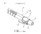
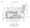
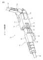
図1及び図2は、本発明の一実施形態によるプラグ型の光コネクタ10を示す図、図3及び図4は、光コネクタ10を備えた本発明の一実施形態によるコネクタ付き光ファイバ12を示す図、図5及び図6は、本発明の他の実施形態によるソケット型の光コネクタ14を示す図、図7及び図8は、光コネクタ14を備えた本発明の他の実施形態によるコネクタ付き光ファイバ16を示す図、図9及び図10は、プラグ型光コネクタ10とソケット型光コネクタ14とを備えた本発明の一実施形態による光ファイバ接続装置18を示す図である。光コネクタ10、14及び光ファイバ接続装置18は、一対の光ファイバ心線の被覆を除去した素線同士を、それぞれの先端面を互いに同軸に突き合わせた状態に接続することができる。Embodiments of the present invention will be described below in detail with reference to the accompanying drawings. Corresponding components are denoted by common reference symbols throughout the drawings.
1 and 2 show a plug-type
図1〜図4に示すように、本発明の一実施形態によるプラグ型光コネクタ10は、光ファイバ心線を内蔵する光伝送線部材の末端に装着して使用されるものであり、本体20と、本体20の所定位置に固定的に設置されるフェルール22と、本体20上でフェルール22に対し予め定めた位置に支持される整列スリーブ部材24とを備えて構成される。本体20は、フェルール22を固定支持する中空筒状のプラグハウジング26と、プラグハウジング26に軸線方向へ隣接して固定的に連結される中空筒状のブーツ28とを備える。プラグハウジング26及びブーツ28は、適当な樹脂材料から作製できる。 As shown in FIGS. 1 to 4, a plug-type
本体20のプラグハウジング26は、軸線方向一端で開口する略円筒状の第1部分30と、軸線方向他端で開口する略円筒状の第2部分32とを一体に備える。第1部分30は、その円筒状内周面によって第1凹部30aを画定し、第2部分32は、その円筒状内周面によって第2凹部32aを画定する。第1凹部30aと第2凹部32aとの間には、両者を連通する中心貫通穴を有する環状壁34が、第1及び第2部分30、32と一体に形成される。環状壁34の中心貫通穴は、第1凹部30a側の大径円筒状の嵌入穴34aと、第2凹部32a側で円錐台状に拡径する案内溝34bと、嵌入穴34aと案内溝34bとを連通する小径円筒状の挿通穴34cとを含む。第1凹部30a、第2凹部32a、嵌入穴34a、案内溝34b及び挿通穴34cは、互いに同軸に整列する。 The
プラグハウジング26の第1部分30には、その開口端30bの近傍で径方向へ対向する位置に、一対の係止穴36が形成され、各係止穴36と開口端30bとの間に、第1部分30の内周面に隣接する案内面36aが設けられる。プラグハウジング26の第1部分30にはさらに、開口端30bに隣接して一体形成される基端38aを有するクランク状のラッチレバー38が、プラグハウジング26の外側で第2部分32に至る長さを有して片持ち式に延設される。ラッチレバー38は、基端38aを支点として弾性的に撓むことにより、第1部分30上でプラグハウジング26に接近及び離反する方向へ揺動できる。ラッチレバー38の長手方向略中央には、その両側縁に一対の係合凹所38bが形成される。 In the
本体20のブーツ28は、軸線方向一端で開口する略円筒状の第1部分40と、軸線方向他端で開口する略円筒状の第2部分42とを一体に備える。第1部分40は、その円筒状内周面によって第1凹部40aを画定し、第2部分42は、その円筒状内周面によって第2凹部42aを画定する。第1凹部40aと第2凹部42aとは、僅かな段差を介して相互に同軸に連通する。ブーツ28の第1部分40は、第1凹部40aに、プラグハウジング26の第2部分32を圧入や接着により固定的に受容する。ブーツ28の第2部分42は、第1凹部40aに受容したプラグハウジング26の第2部分32の第2凹部32aに、第2凹部42aが連通した状態を維持しつつ、外力によって比較的容易に撓曲される可撓性を有する。ブーツ28の第2部分42には、その任意の撓曲形態を自己保持するための可撓ワイヤ44が内設される。 The
光コネクタ10のフェルール22は、図11に単体で示すように、中心軸線22aに沿ってファイバ保持用の1つの貫通孔を形成した筒状部材であり、その全体が、円筒状外周面22bを有する単心用の心出し部として機能する。フェルール22は、中心軸線22aに略直交して平坦に延設される軸線方向一端の衝合端面46と、衝合端面46の中心に開口し、中心軸線22aに沿って直線状に延びる素線保持孔48とを備える。衝合端面46は、テーパ面22cを介して円筒状外周面22bに連通する。素線保持孔48は、衝合端面46の反対側で、テーパ状の案内面48aにより拡径されて、軸線方向他端の環状端面22dに開口する。 As shown in FIG. 11, the
フェルール22は、その環状端面22dの近傍部分で、圧入や接着により、プラグハウジング26の環状壁34の嵌入穴34aに固定される。この状態で、フェルール22の主要長さ部分は、プラグハウジング26の第1部分30の第1凹部30a内に、隙間を介して実質的同軸に配置される。また、フェルール22の衝合端面46は、プラグハウジング26の第1部分30の開口端30bよりも僅かに外方へ突出して位置決めされる。なおフェルール22は、セラミックス、樹脂、金属等から作製できる。 The
光コネクタ10の整列スリーブ部材24は、図12及び図13に示すように、中空円筒状の割りスリーブ50と、割りスリーブ50を収容する中空筒状のスリーブホルダ52と、スリーブホルダ52に支持されて割りスリーブ50内に延出する可動シャッタ54とを備える。整列スリーブ部材24の割りスリーブ50は、円筒状に曲成された金属板等の弾性薄板部材からなり、中心軸線50aを規定する全体に一様な内周面50b及び外周面50cを有するとともに、それら内外周面50b、50cの周方向1箇所に、軸線方向全長に渡って延びるスリット56を有する。割りスリーブ50は、内周面50bによって画定される空洞部58の内径寸法を、それ自体の弾性復元力下で全体に一様に拡縮できる。 As shown in FIGS. 12 and 13, the
整列スリーブ部材24のスリーブホルダ52は、軸線方向一端で開口する略円筒状の第1部分60と、軸線方向他端で開口する略円筒状の第2部分62とを備える。第1部分60は、その円筒状内周面によって第1凹部60aを画定し、第2部分62は、その円筒状内周面によって第2凹部62aを画定する。第1凹部60aと第2凹部62aとは、互いに同一の内径を有して段差無く相互に連通する。スリーブホルダ52の第1部分60は、後述するように、光コネクタ10とその相手方コネクタ(例えば光コネクタ14)との接続時に、本体20の外側にプラグ状に突出して相手方コネクタのソケット状嵌合部に相補的に嵌合する相手コネクタ嵌合部として機能する。 The
スリーブホルダ52の第1部分60には、その開口端60bに隣接して、テーパ状の案内面64aを有する環状爪64が径方向内方へ突設され、開口端60bから離隔した位置で、環状フランジ66が径方向外方へ突設される。同様に第2部分62には、その開口端62bに隣接して、テーパ状の案内面68aを有する環状爪68が径方向内方へ突設され、開口端62bから離隔した位置で、環状フランジ70が径方向外方へ突設される。図示実施形態では、第1部分60と第2部分62とは、互いに別体に作製されて、それぞれの環状フランジ66、70を隣接させた位置関係で互いに組み合わされる。 In the
スリーブホルダ52の第2部分62にはさらに、環状フランジ70上の互いに径方向反対の位置に一体形成される基端72aをそれぞれに有する一対の係合片72が、第2部分62の外周面に沿っていずれも片持ち式に延設される。各係合片72は、基端72aを支点として弾性的に撓むことにより、第2部分62上でスリーブホルダ52に接近及び離反する方向へ揺動できる。各係合片72の長手方向略中央には、その外面に係合突起72bが形成される。スリーブホルダ52は、第1及び第2部分60、62の第1及び第2凹部60a、62aに、無負荷状態の割りスリーブ50を、適当な隙間を介して収容する。このとき割りスリーブ50は、第1及び第2部分60、62の環状爪64、68によって、第1及び第2凹部60a、62aから脱落しないように保持される。なおスリーブホルダ52は、適当な樹脂材料から作製できる。 The
整列スリーブ部材24の可動シャッタ54は、略J字状に曲成された金属板等の弾性薄板部材からなり、直線状に延びる支持部分54aと、支持部分54aよりも幾分短く、湾曲して延びる腕部分54bとを一体に有する。可動シャッタ54は、支持部分54aの末端に形成される取付片54cが、スリーブホルダ52の第1部分60と第2部分62との間に固定的に挟持されて、支持部分54aを第1部分60の内周面に沿って軸線方向へ延ばした状態で、スリーブホルダ52に片持ち式に支持される。この状態で、可動シャッタ54の腕部分54bは、割りスリーブ50のスリット56を通して空洞部58内に延長され、その末端54dが、割りスリーブ50の中心軸線50aに重畳する位置に配置される。可動シャッタ54の腕部分54bは、支持部分54aとの連結部位を支点として弾性的に撓むことにより、割りスリーブ50のスリット56に接近及び離反する方向へ揺動できる。すなわち可動シャッタ54の腕部分54bは、割りスリーブ50の空洞部58に受動的変位可能に設置される。 The
整列スリーブ部材24は、スリーブホルダ52の第2部分62が、本体20のプラグハウジング26の第1部分30に受容されることにより、本体20に着脱可能に取り付けられる。このとき、スリーブホルダ52の第2部分62をプラグハウジング26の第1部分30の第1凹部30aに挿入するに従い、スリーブホルダ52の一対の係合片72は、第1部分30の対応の案内面36aに押圧されて径方向内方へ撓み、最終的にそれら係合片72の係合突起72bが、第1部分30の対応の係止穴36にスナップ式に嵌着される。それと共に、プラグハウジング26に固定されたフェルール22の主要長さ部分が、スリーブホルダ52の第2部分62の開口端62bを通過して、割りスリーブ50の空洞部58に嵌入される。その結果、整列スリーブ部材24が本体20のプラグハウジング26上で適正位置に配置される。 The
整列スリーブ部材24が本体20に対し適正位置に配置された状態では、スリーブホルダ52の第2凹部62aに実質的に対応する長さの割りスリーブ50の空洞部58の一部分に、衝合端面46に隣接するフェルール22の任意長さ部分が受容される。この状態で、割りスリーブ50は、その内周面50bがフェルール22の円筒状外周面22bに密接して僅かに弾性的に押し拡げられ、その弾性復元力下でフェルール22を所定位置に心出し支持する。すなわちこの状態で、フェルール22の中心軸線22aは、割りスリーブ50の中心軸線50aに精確に整合して固定的に配置され、割りスリーブ50がフェルール22に対し予め定めた心出し位置に支持される。 In a state where the
また、この適正取付位置で、整列スリーブ部材24の可動シャッタ54は、その腕部分54bの末端54dが、フェルール22の衝合端面46から離隔して、中心軸線22a上で素線保持穴48の開口の軸線方向前方に重畳して配置される。したがって可動シャッタ54は、フェルール22の衝合端面46とスリーブホルダ52の第1部分60の開口端60bとの間で、腕部分54bが割りスリーブ50の空洞部58内に突出して、フェルール22を通して放出される光を開口端60bの位置まで到達しないように遮断できる。 Further, at this proper mounting position, the
整列スリーブ部材24を本体20から取り外す際には、スリーブホルダ52の両係合片72の係合突起72bを、プラグハウジング26の第1部分30の外側から、係止穴36内に強制的に押し込んで、係合突起72bと係止穴36とのスナップ式係合を解除する。その状態で、整列スリーブ部材24をプラグハウジング26から引き抜くことにより、割りスリーブ50がフェルール22から離脱して、整列スリーブ部材24が本体20から取り外される。なお、整列スリーブ部材24を本体20上に固定的に設置するための係合突起72bと係止穴36とのスナップ式係合は、専用工具を用いずに手作業で解除できることが有利であるが、光コネクタ10と相手方コネクタ(例えば光コネクタ14)との接続/分離時に整列スリーブ部材24が本体20から不用意に脱落しない信頼性を有することが望ましい。 When the
上記したプラグ型の光コネクタ10は、整列スリーブ部材24を本体20に取り付けた状態で、光ファイバ心線80を内蔵する光ファイバコード82の末端に装着されることにより、コネクタ付き光ファイバ12を構成することができる(図3及び図4)。ここで、光ファイバコード82は予め線端処理として、図14(a)に示すように、その末端の所望長さに渡り樹脂外被84及び抗張力材(図示せず)が除去されて光ファイバ心線80が露出されるとともに、光ファイバ心線80の先端所望長さに渡り被覆86が除去されて光ファイバ素線88が露出され、露出した光ファイバ素線88が専用の切断工具で、少なくともフェルール22の素線保持孔48に実質的に対応する長さに切断される。 The plug-type
このように線端処理を施した光ファイバコード82は、光コネクタ10の本体20のブーツ28に挿入されて、先端で露出した光ファイバ素線88が、プラグハウジング26の環状壁34の案内溝34b及び挿通穴34cを通して、第1凹部30aに固定的に設置されたフェルール22の案内面48aから素線保持孔48に挿通される。そして、光ファイバ素線88の軸線方向端面88aが、フェルール22の衝合端面46に隣接する所定位置に達した時点で、例えば、光ファイバ素線88と光ファイバ心線80の被覆86との少なくとも一方がフェルール22とプラグハウジング26(挿通穴34c)との少なくとも一方に接着剤で固定されるとともに、光ファイバコード82の外被84がプラグハウジング26の第2凹部32aに接着剤で固定される。このようにして、光ファイバコード82の末端に光コネクタ10が装着され、コネクタ付き光ファイバ12が完成する。 The
上記構成を有する光コネクタ10は、本体20に設置されたフェルール22の衝合端面48を含む部分を空洞部58に受容する整列スリーブ部材24を装備しているから、フェルール22の特に衝合端面48に対する人手の接触や塵埃の付着を、未然に防止することができる。整列スリーブ部材24は本体20に対し着脱可能であるから、フェルール22の周辺領域を清掃したいときには、整列スリーブ部材24を本体20から取り外すことにより容易に清掃できる。なお、このような作用効果は、可動シャッタ54を備えていない場合にも奏されるものである。 The
さらに光コネクタ10によれば、整列スリーブ部材24に可動シャッタ54を内蔵しているから、光コネクタ10を光ファイバ心線80に装着した状態で相手方コネクタとは接続していない間に、フェルール22を通して光ファイバ素線88から放出される光がプラグハウジング26の開口端30bから外方へ漏出することを、可動シャッタ54により確実に防止することができる。可動シャッタ54は整列スリーブ部材24の空洞部58内に設置されるので、不用意に可動シャッタ54を動作させてしまう危惧もない。また、フェルール22に支持される整列スリーブ部材24に可動シャッタ54を設けたから、光コネクタ10の外形に関わらず、光遮断機能を容易に付与することができる。このように光コネクタ10は、優れた防汚機能及び光遮断機能を有するものである。 Further, according to the
また、上記構成を有するコネクタ付き光ファイバ12は、光コネクタ10に関する優れた防汚機能及び光遮断機能を有するものとなる。したがってコネクタ付き光ファイバ12は、例えば一般家庭のように使用者の知識や熟練が乏しい場合にも、高度な保全性を発揮して、安定性及び信頼度の高い光伝送路の構築に寄与することができる。なお、光コネクタ10は、複数のフェルール22及び個々のフェルール22に対応する複数の整列スリーブ部材24を備えることにより、多心光コネクタとして構成することもできる。 Moreover, the
図5〜図8に示すように、本発明の他の実施形態によるソケット型光コネクタ14は、光ファイバ心線を内蔵する光伝送線部材の末端に装着して使用されるものであり、本体90と、本体90の所定位置に設置されるフェルール92と、本体90に設置され、フェルール92に取り付けられる光ファイバ心線を有する光伝送線部材を固定的に保持する保持部94とを備えて構成される。本体90は、フェルール92を固定支持する筒状のソケットブロック96と、ソケットブロック96を軸線方向変位可能に支持する中空筒状のソケットハウジング98とを備える。ソケットブロック96及びソケットハウジング98は、適当な樹脂材料から作製できる。 As shown in FIGS. 5 to 8, a socket-type
本体90のソケットブロック96は、軸線方向一端で開口する略円筒状の第1部分100と、軸線方向他端側で側方に開口する筒状の第2部分102とを一体に備える。第1部分100は、その円筒状内周面によって第1凹部100aを画定し、第2部分102は、その略直方体の内面によって第2凹部102aを画定する。第1凹部100aと第2凹部102aとの間には、両者を連通する中心貫通穴を有する環状壁104が、第1及び第2部分100、102と一体に形成される。環状壁104の中心貫通穴は、第1凹部100a側の大径円筒状の嵌入穴104aと、第2凹部102a側の小径円筒状の挿通穴104bとを含む。第2部分102はさらに、第2凹部102aに連通する中心貫通穴を有してソケットブロック96の軸線方向他端に設置される後端壁106を備える。後端壁106の中心貫通穴は、第2凹部102a側の小径円筒状の挿通穴106aと、外面に向かって円錐台状に拡径する案内溝106bとを含む。第1凹部100a、嵌入穴104a、挿通穴104b、挿通穴106a及び案内溝106bは、互いに同軸に整列する。 The
ソケットブロック96の第1部分100には、その開口端100bに隣接して、径方向外方へ突出する環状フランジ108が形成される。さらに、環状フランジ108の所定位置に、径方向外方へ局所的に突出する抜け止め108a及び回り止め108bが形成される。ソケットブロック96の第2部分102には、被覆を除去した光ファイバ素線を固定的に挟持する開閉可能な素線固定部材110と、素線固定部材110を開閉動作させる作動部材112とが、適正に組み合わせて第2凹部102aに収容される。 The
図15に示すように、素線固定部材110は、アルミニウム等の展性材料から予め所定形状に成形した薄板状部材を、その中心線に沿って二つ折りに畳んだ形態を有する。二つ折りの素線固定部材110は、折り目に沿った蝶番縁110aを介して対向配置される一対の翼114を備え、それら翼114の相互対向面に、光ファイバ素線を固定的に挟持する開閉可能な挟持面114aがそれぞれ形成される。図示実施形態では、両翼114の挟持面114aの対応位置に、光ファイバ素線を予め定めた位置に挟持するための直線状の支持溝116(例えば断面V字状のV溝)が、蝶番縁110aに平行にそれぞれ形成される。 As shown in FIG. 15, the
素線固定部材110の一対の翼114は、蝶番縁110aの領域における材料の弾性変形を伴いつつ、蝶番縁110aを中心として揺動すなわち開閉動作できるようになっている。通常は素線固定部材110は、両翼114がそれぞれの挟持面114a同士を若干離隔させた開位置(図15)に置かれ、この開位置から、両翼114に相互接近方向への外力を加えることにより、蝶番縁110aの弾性復元力に抗して、それぞれの挟持面114aが密接する閉位置へと変位する。素線固定部材110が開位置にあるときには、支持溝116に対する光ファイバ素線の円滑な出し入れが許容され、素線固定部材110が閉位置にあるときには、一対の支持溝116の間に受容された光ファイバ素線が両挟持面114aから圧力を受けて強固に固定的に挟持される。なお、素線固定部材110は、各支持溝116の幅を適宜調整して形成することにより、両支持溝116の間に、被覆を有する光ファイバ心線を固定的に挟持する構成とすることもできる。 The pair of
作動部材112は、例えば樹脂材料の一体成形品からなる蓋状部材であり、素線固定部材110の両翼114を受容可能な寸法の凹所118を画定する一対の抱持壁120を備える。それら抱持壁120は、互いに所定間隔を空けて略平行に対向し、それぞれの相互対向面が、凹所118の開口(図で下端)側の一次加圧面120aと、凹所118の内奥側の二次加圧面120bとを有する段付面として形成される。したがって凹所118には、両一次加圧面120aによって画定される比較的幅広の開口側領域と、両二次加圧面120bによって画定される比較的狭隘な内奥側領域とが形成される。 The actuating
素線固定部材110は、ソケットブロック96の第2部分102の第2凹部102aに、蝶番縁110aを内奥に向けて、上記開閉動作が可能な状態で収納される。素線固定部材110をソケットブロック96の第2凹部102aの適正位置に収納すると、両支持溝116は、ソケットブロック96の一対の挿通穴104b、106aに対し同軸状に整列できるように配置される。作動部材112は、ソケットブロック96の第2部分102の開口領域を相補的に塞ぐようにして、第2凹部102aに移動可能に取り付けられる。このとき作動部材112は、凹所118に素線固定部材110の両翼114を受容して、両抱持壁120がそれぞれの加圧面120a、120bで段階的に、両翼114を外側から抱き込むように支持する。作動部材112は、ソケットブロック96に対し仮取付位置(図6及び図8)から最終取付位置に移動する間に、両抱持壁120から素線固定部材110の両翼114にそれらの挟持面114aを密接させる方向への圧力を加えて、素線固定部材110を開位置から閉位置へと変位動作させる。 The
本体90のソケットハウジング98は、軸線方向一端で開口する筒状の第1部分122と、軸線方向他端で開口する筒状の第2部分124とを一体に備える。第1部分122は、その円筒状内周面によって第1凹部122aを画定し、第2部分124は、その円筒状内周面によって第2凹部124aを画定する。第1凹部122aと第2凹部124aとは、段差(肩面126)を介して相互に同軸に連通する。ソケットハウジング98は、第1部分122の第1凹部122aに、ソケットブロック96の第1部分100を軸線方向変位可能に収容するとともに、第2部分124の第2凹部124aに、ソケットブロック96の第2部分102を軸線方向変位可能に収容する。 The
ソケットハウジング98の第1凹部122aにはさらに、肩面126とソケットブロック96の環状フランジ108との間に圧縮可能な状態で介在する圧縮コイルばね128が、ソケットブロック96の第1部分100を囲繞する配置で収容される。圧縮コイルばね128は、ソケットブロック96をソケットハウジング98の第1部分122の開口端122bから外方へ押し出す方向へ弾性的に付勢する。また、ソケットハウジング98の第1部分122には、開口端122bの近傍所定位置に、ソケットブロック96の環状ハウジング108に設けた抜け止め108a及び回り止め108bを相補的に受容する複数の凹所130が形成される。それにより、ソケットブロック96は、ソケットハウジング98に対し、圧縮コイルばね128の付勢力下で軸線方向へのみ所定距離に渡って変位できる。 The
ソケットハウジング98の第2部分124には、ソケットブロック96の第2部分102に設置された作動部材112に対応する位置に、側方へ開口する操作窓132が形成される。操作窓132は、作動部材112を前述した仮取付位置から最終取付位置に移動させるための適当な工具の挿入を許容する。ソケットハウジング98の第2部分124にはさらに、第1部分122との境界領域で外面上の互いに径方向反対の位置に一体形成される基端134aをそれぞれに有する一対のラッチレバー134が、第2部分124の外面に沿っていずれも片持ち式に延設される。各ラッチレバー134は、基端134aを支点として弾性的に撓むことにより、第2部分124上でソケットハウジング98に接近及び離反する方向へ揺動できる。各ラッチレバー134の長手方向略中央には、その外面に係合突起134bが形成される。 An
光コネクタ14のフェルール92は、前述した光コネクタ10のフェルール22と実質的同一の構成を有する。すなわちフェルール92は、中心軸線92aに略直交して平坦に延設される軸線方向一端の衝合端面136と、衝合端面136の中心に開口し、中心軸線に沿って直線状に延びる素線保持孔138とを備える。衝合端面136は、テーパ面92cを介して円筒状外周面92bに連通する。 The
フェルール92は、衝合端面136の反対側の環状端面92dの近傍部分で、圧入や接着により、ソケットブロック96の環状壁104の嵌入穴104aに固定される。この状態で、フェルール92の主要長さ部分は、ソケットブロック96の第1部分100の第1凹部100a内に、隙間を介して実質的同軸に配置される。また、フェルール92の衝合端面136は、ソケットブロック96の第1部分100の開口端100bよりも僅かに外方へ突出して位置決めされる。 The
ソケットブロック96に固定されたフェルール92は、ソケットブロック96と共に、ソケットハウジング98に対して軸線方向へ所定距離に渡って変位できる。ソケットブロック96が圧縮コイルばね128の付勢によりソケットハウジング98の第1部分122の開口端122b側に偏倚した前端位置では、フェルール92の衝合端面136が、ソケットハウジング98の開口端122bよりも僅かに外方へ突出して配置される。また、ソケットブロック96が圧縮コイルばね128の付勢に抗してソケットハウジング98の第2部分124の開口端124b側に偏倚した後端位置では、フェルール92の衝合端面136が、ソケットハウジング98の開口端122bと略同一の仮想平面上に配置される。このような構成により、光コネクタ14を相手方コネクタ(例えば光コネクタ10)と接続する際に、別途用意される整列スリーブ部材(例えば光コネクタ10の整列スリーブ部材24)の中で、両コネクタのフェルールの衝合端面同士を圧縮コイルばね128のばね付勢力下で衝合させて、一対の光ファイバ心線同士を高精度に心合わせした端面突き合わせ状態で接続することができる。 The
光コネクタ14の保持部94は、本体90のソケットハウジング98の第2部分124に隣接して、その開口端124b(或いはソケットブロック96に固定されたフェルール92の環状端面92d)から所定距離だけ離れた位置に配置される保持部材140を備える。保持部材140は、ソケットハウジング98の第2部分124から第1部分122とは反対側へ一体に延長された第3部分142上に、ソケットブロック96に固定されたフェルール92の中心軸線92aに略直交する方向へ延びる回転軸線140aを有して回動可能に設置される。或いは保持部材140を、ソケットハウジング98の第3部分142に一体に(すなわち固定して)形成することもできる。 The holding
保持部材140は、例えば樹脂材料の一体成形品からなり、回転軸線140aを中心とした円板形状を有する基板部分144と、基板部分144から外方へ放射状に延設される断面U字状の延長部分146とを備える。保持部材140の基板部分144には、回転軸線140aを含まない外周近傍の略弓形の領域に、回転軸線方向へ突出する隆起148が設けられる。隆起148は、その回転軸線140a側の面に、光コネクタ14の装着対象となる光ファイバ心線に規定される最小曲げ半径よりも僅かに大きな所定曲率半径で円弧状に湾曲膨出する心線ガイド面148aを有する。さらに基板部分144は、隆起148とは反対側の所定中心角度位置で外周面上に局所的に突設される複数の突起144aを有する。各突起144aは、ソケットハウジング98の第3部分142の所定位置に形成した台座150上の係止溝150aに、関連する構成要素群の微小な弾性変形を伴いつつ嵌合する。 The holding
保持部材140の延長部分146には、光伝送線部材を直線状に延ばした状態で受容可能な保持溝152が形成される。保持溝152は、基板部分144に隣接するその基端152aで、隆起148の心線ガイド面148aに実質的に連続して、円弧状の心線ガイド面148aの略接線方向へ延長される。また保持溝152には、延長部分146の内面所望箇所に、光伝送線部材の外被に摩擦係合する複数の突起152bが形成される。保持部材140が図示の機能位置にあるときに、延長部分146の保持溝152は、本体90のソケットブロック96の後端壁106(或いはソケットブロック96に固定されたフェルール92の環状端面92d)から見て、回転軸線140a及び隆起148の心線ガイド面148aの双方よりも遠い位置に配置されるとともに、ソケットブロック96に固定されたフェルール92の中心軸線92a(すなわち素線保持孔138)に対し、所定角度で傾斜する方向へ延設される(図16(a)参照)。また、この機能位置において、基板部分144の隆起148の心線ガイド面148aは、ソケットハウジング98の第3部分142の台座150から見て、回転軸線140aよりも遠い位置に配置される。 The
保持部材140に設けた保持溝152は、上記した配置構成を有することにより、本体90のソケットハウジング98上でのフェルール92の位置に関わらず、光伝送線部材の光ファイバ心線を、予め定めた最小曲げ半径以上の曲げ半径で撓曲させるように機能する。このような光ファイバ心線の撓曲は、フェルール92の中心軸線92aに対する保持溝152の傾斜角度及び保持溝152とフェルール92との間の距離に依存して確立されるものである。また、隆起148の心線ガイド面148aは、保持溝152により撓曲された光ファイバ心線に近接して通常は接触しない位置に形成される。心線ガイド面148aは、撓曲状態にある光ファイバ心線が意図しない外力により最小曲げ半径未満の曲げ半径で撓曲してしまうことを、効果的に防止する。或いは、心線ガイド面148aは、撓曲状態の光ファイバ心線に張力を生じない程度に軽く接触することにより、曲げ作用を補助することもできる。 Since the holding
なお、図示の機能位置では、保持部材140の基板部分144に設けた1つの突起144aが、ソケットハウジング98の台座150の係止溝150aに嵌合して、保持部材140の不用意な回動を阻止する。また、保持部材140をソケットハウジング98の第3部分142に一体に形成した場合には、基板部分144及び延長部分146は図示の機能位置に予め固定して配置される。 In the illustrated functional position, one protrusion 144a provided on the
本体90に対して回動可能に設置された保持部材140は、延長部分146の保持溝152が、本体90のソケットブロック96の後端壁106から見て、回転軸線140a及び隆起148の心線ガイド面148aの双方よりも遠い位置で、ソケットブロック96に固定されたフェルール92の中心軸線92a(すなわち素線保持孔138)に略平行な方向へ(或いは中心軸線92aの延長線上に)延設される非機能位置に配置できる(図16(b)参照)。この非機能位置では、保持部材140の基板部分144に設けた他の1つの突起144aが、ソケットハウジング98の台座150の係止溝150aに嵌合して、保持部材140の不用意な回動を阻止する。後述するように保持部材140は、光コネクタ14を光伝送線部材に装着するときに、機能位置と非機能位置との間で適宜回動させられる。 The holding
上記したソケット型の光コネクタ14は、光ファイバ心線160を内蔵する光ファイバケーブル162の末端に装着されることにより、コネクタ付き光ファイバ16を構成することができる(図7及び図8)。ここで、光ファイバケーブル162は予め線端処理として、図14(b)に示すように、その末端の所望長さに渡り樹脂外被164及び抗張力体(図示せず)が除去されて光ファイバ心線160が露出されるとともに、光ファイバ心線160の先端所望長さに渡り被覆166が除去されて光ファイバ素線168が露出され、露出した光ファイバ素線168が専用の切断工具で、少なくともフェルール92の素線保持孔138に実質的に対応する長さに切断される。 The socket-type
このように線端処理を施した光ファイバケーブル162は、光コネクタ14の本体90のソケットブロック96にその後端壁106から挿入される。このとき、ソケットブロック96の第2部分102に設置した作動部材112は前述した仮取付位置に置かれ、それにより素線固定部材110が開位置に置かれている。また、保持部94の保持部材140は前述した非機能位置に置かれている。 The
そこで、光ファイバケーブル162の先端で露出した光ファイバ素線168は、ソケットブロック96の後端壁106の案内溝106b及び挿通穴106aを通過して、素線固定部材110の一対の支持溝116の間を通り、さらにソケットブロック96の環状壁104の挿通穴104bを通して、第1凹部100aに固定的に設置されたフェルール92の素線保持孔138に挿通される。そして、光ファイバ素線168の軸線方向端面168aが、フェルール92の衝合端面136に隣接する所定位置に達した時点で、作動部材112を仮取付位置から最終取付位置に押し込んで素線固定部材110を閉位置に変位させ、光ファイバ素線168(又は光ファイバ心線160)を一対の支持溝116の間に固定的に挟持する。 Therefore, the
このように光ファイバ素線168をソケットブロック96に対し固定した後に、光ファイバケーブル162を保持部材140の延長部分146の保持溝152に、前者の外被164に後者の複数の突起152bを食い込ませつつ嵌入する。この状態で、光ファイバケーブル162は、フェルール92の衝合端面136から保持溝152の末端に至る範囲で光ファイバ素線168が真っ直ぐに延びた形態に保持される(図16(b))。次いで、保持部材140を非機能位置から機能位置へ回動させて、保持溝152をフェルール92の中心軸線92aに対し所定角度で傾斜する位置に配置する。 After the
保持部材140を非機能位置から機能位置へ回転させるに従い、保持部材140の基板部分144に沿って延びている光ファイバ心線160は、隆起148の心線ガイド面148aに徐々に接近する。そして保持部材140が機能位置に到達すると、光ファイバ心線160は、ソケットブロック96の後端壁106から保持溝152の基端152aに至る範囲で、前述したように隆起148の心線ガイド面148aに近接して湾曲した形態を呈する(図16(a))。このとき、心線ガイド面148aの存在により、光ファイバ心線160が規定値の最小曲げ半径よりも小さな半径で曲がることは確実に回避される。しかも、光ファイバケーブル162がソケットブロック96の後端壁106から見て心線ガイド面148aよりも遠い位置で保持溝152に保持されているので、ソケットブロック96が前述したようにソケットハウジング98に対し軸線方向へ変位する際に、光ファイバ心線160は心線ガイド面148aに近接して、規定の最小曲げ半径よりも小さな半径にならない範囲で僅かに撓むことが許容される。このようにして、光ファイバケーブル162の末端に光コネクタ14が装着され、コネクタ付き光ファイバ16が完成する。 As the holding
上記構成を有する光コネクタ14は、本体90に設置されたフェルール92を受容する整列スリーブ部材を装備しておらず、しかも、装着対象の光ファイバ心線160をフェルール92の後方で規定値の最小曲げ半径以上の半径で曲げて保持できるから、光ファイバ心線160内での光損失を抑制しつつ、使用時におけるフェルール92の延長方向への外形寸法を効果的に削減することができる。このような光ファイバ心線160の撓曲は、保持部94に設けた保持溝152に予め設定された配置構成に従って確立されるものであるから、例えば工事現場で光ファイバケーブル162に対するコネクタ装着作業を実施する場合にも、迅速かつ正確に光コネクタ14を光ファイバ心線160に装着することができる。保持部94を回動式の保持部材140から構成すれば、光ファイバ心線160に捻りや引張り等の応力を不用意に集中させること無く、光ファイバ心線160を所定の曲げ半径に曲げることができるので、現場でのコネクタ装着作業が著しく容易になる。 The
さらに、光コネクタ14によれば、使用時にソケットブロック96と保持溝152との間で心線ガイド面148aに沿って湾曲して延びる光ファイバ心線160は、光コネクタ14を相手方コネクタ(例えば光コネクタ10)と接続する際にソケットブロック96が圧縮コイルばね128の付勢に抗して軸線方向後方へ移動したときにも、心線ガイド面148aの近傍で、規定の最小曲げ半径よりも小さな半径にならない範囲で僅かに撓むことができる。したがって、光損失の少ない接続部を安定的に構成できる。さらに、整列スリーブ部材を備えない光コネクタ14の構成は、フェルール周辺領域の清掃を容易にする効果も奏する。また、フェルール92と光ファイバ素線168とは、ソケットブロック96に設けた素線固定部材110及び作動部材112の作用により相互に固定されるから、接着剤を用いる必要が無く、現場でのコネクタ装着作業を一層迅速に実施できる。このように光コネクタ14は、フェルール延長方向への外形寸法を効果的に削減でき、しかも、優れた現場施工性及び保全性を有するものである。 Furthermore, according to the
また、上記構成を有するコネクタ付き光ファイバ16は、光コネクタ14に関する外形寸法の削減効果並びに優れた現場施工性及び保全性を有するものとなる。したがってコネクタ付き光ファイバ16は、例えば公共の光ファイバネットワークから光ファイバケーブルを個々の家屋まで延長して敷設する引込工事において、家屋の壁の内部に金属管を用いて配線される光ファイバケーブルとして、特に好適に使用できる。この用途では、ソケット型の光コネクタ14は、室内の所望位置に設けられるスイッチボックスに、光ファイバケーブル162内での光損失を抑制しつつ、十分な空間的余裕を持って収容できる。なお、光コネクタ14に装備した保持部94の構成は、図示実施形態のようなソケット型の光コネクタに限らず、光コネクタ10のようなプラグ型の光コネクタにも搭載できる。また、光コネクタ14は、複数のフェルール92及び個々のフェルール92に対応する複数の保持部94を備えることにより、多心光コネクタとして構成することもできる。 Moreover, the
前述したプラグ型の光コネクタ10とソケット型の光コネクタ14とは、図9及び図10に示すように、互いに着脱自在に組み合わされて、光ファイバ接続装置18を構成する。光ファイバ接続装置18において、光ファイバコード82の末端に装着した光コネクタ10と光ファイバケーブル162の末端に装着した光コネクタ14とを互いに接続する際には、光コネクタ10の本体20に取り付けた整列スリーブ部材24のスリーブホルダ52の第1部分60を、光コネクタ14のソケットブロック96の第1凹部100aに嵌入する。ここで、整列スリーブ部材24の第1部分60とソケットブロック96の第1凹部100aとは、互いにがたつき無く相補的に嵌合可能な形状及び寸法を有するように形成される。 The plug-type
整列スリーブ部材24をソケットブロック96に嵌入するに伴い、光コネクタ14のフェルール92はその衝合端面138から、整列スリーブ部材24の割りスリーブ50内に嵌入される。ここで、両コネクタ10、14のフェルール22、92を同一の寸法及び形状に形成しておくことにより、フェルール92は、衝合端面138に隣接する任意長さ部分が、スリーブホルダ52の第1部分60の開口端60bを通過して、光コネクタ10のフェルール22の衝合端面46に突き当たるまで、割りスリーブ50の空洞部58に挿入される(図10)。その状態で、割りスリーブ50は、その内周面50bがフェルール92の円筒状外周面92bに密接して僅かに弾性的に押し拡げられ、その弾性復元力下でフェルール92を所定位置に心出し支持する。したがってこの状態で、フェルール92の中心軸線92aは、割りスリーブ50の中心軸線50aすなわちフェルール22の中心軸線22aに精確に整合して固定的に配置される。さらに、両フェルール22、92の衝合端面46、136同士が、圧縮コイルばね128の付勢力下で密接して衝合し、それにより、両フェルール22、92に固定した一対の光ファイバ素線88、168同士が高精度に心合わせした端面突き合わせ状態で接続される。 As the
光コネクタ14のフェルール92が整列スリーブ部材24の割りスリーブ50の空洞部58に挿入されると、予め割りスリーブ50の空洞部58に受動的変位可能に配置されている可動シャッタ54の腕部分54bは、その末端54dでフェルール92に衝突して弾性的に撓み、割りスリーブ50のスリット56に受動的に引き込まれる(図10)。したがって可動シャッタ54は、フェルール22、92の衝合による光ファイバ素線88、168同士の端面突き合わせ接続を妨害しない。そして、光コネクタ10、14を互いに脱離すると、光コネクタ14のフェルール92が整列スリーブ部材24の割りスリーブ50の空洞部58から引き抜かれるに伴い、可動シャッタ54の腕部分54bは弾性的に復元して、その末端54dが割りスリーブ50の空洞部58内でフェルール22の中心軸線22aの延長線上に配置される。 When the
上記構成を有する光ファイバ接続装置18は、前述した光コネクタ10、14並びにコネクタ付き光ファイバ12、16の作用効果が相乗的に働いて、特に、屋内配線される光伝送路に好適に適用できるものとなることが理解されよう。なお、本発明に係る光ファイバ接続装置並びに本発明に係る光コネクタ及びコネクタ付き光ファイバにおいては、一対のフェルールの衝合端面同士を圧力下で衝合させるための可動フェルール構造(図示実施形態ではフェルール92を支持するソケットブロック96)及び付勢手段(図示実施形態では圧縮コイルばね128)は、ソケット型光コネクタに設ける図示構成に代えて、プラグ型光コネクタに設けたり双方の光コネクタに設けたりすることができる。また、ソケット型光コネクタにおいてフェルールに対し光ファイバ心線を固定する手段は、図示実施形態の素線固定部材110及び作動部材112を用いる構成に代えて、相互密着状態に弾性的に保持される一対の板をこじ開けて光ファイバ素線を挟み込むような構成や、一般的な熱硬化型、熱可塑型、紫外線硬化型等の接着剤を用いる構成を採用できる。さらに、プラグ型光コネクタにおいてフェルールに対し光ファイバ心線を固定する手段として、接着剤の代わりに素線固定部材110のような機械的固定構造を採用することもできる。 The optical
光ファイバ接続装置18を、前述した屋内配線される光伝送路に使用する場合には、ソケット型の光コネクタ14を、既存のスイッチボックスに安定的に設置するための専用のアダプタ170を用いることができる。図17に示すように、アダプタ170は、光コネクタ14の本体90のソケットハウジング98を固定的に抱持する上下一対のアダプタ部材172、174を組み合わせて構成される。それらアダプタ部材172、174は、互いに協働して、光コネクタ14のソケットハウジング98の第1及び第2部分122、124を固定的に受容する第1空洞部分176と、光コネクタ10のプラグハウジング26の第1部分30を挿抜自在に受容する第2空洞部分178とを形成する。 When the optical
アダプタ170の第1空洞部分176には、光コネクタ14のソケットハウジング98を挿入する開口176aの近傍に、ソケットハウジング98に設けた一対のラッチレバー134の係合突起134bをスナップ式に嵌着させる一対の係止穴180が形成される(図18)。また、第2空洞部分178には、光コネクタ10のプラグハウジング26を挿入する開口178aの近傍に、プラグハウジング26に設けたラッチレバー38の一対の係合凹所38bをスナップ式に嵌着させる一対の係止爪182が形成される(図19)。第2空洞部分178にはまた、光コネクタ10のプラグハウジング26を光コネクタ14のソケットハウジング98に向けて摺動式に案内するリブ184が形成される。アダプタ170は、両アダプタ部材172、174の前端面172b、174bをスイッチボックス(図示せず)の開口に配置して、スイッチボックスに固定的に取り付けられる。 An
アダプタ170はさらに、第2空洞部分178の開口178aを開閉自在に閉鎖するドア186を有する。ドア186は例えば、開口178aの内側で上ハウジング部材172に蝶番式に連結される。ドア186は、一対の光コネクタ10、14同士を接続しない光ファイバ接続装置18の非使用時には、自重又は図示しないばね等の付勢力により、アダプタ170の第2空洞部分178の開口178aを閉鎖する。それにより、スイッチボックスに収容される光コネクタ14のフェルール92の衝合端面136への人手の接触や塵埃の付着が未然に防止されるとともに、フェルール92を通して光ファイバ素線168から放出される光がスイッチボックスから漏出することが確実に防止される。 The
光ファイバ接続装置18の使用時には、光コネクタ10を、その整列スリーブ部材24の開口端60bをドア186に外側から押し付けて、アダプタ170の第2空洞部分178に挿入することにより、ドア186が上アダプタ部材172側に回動式に押し上げられて開口178aが開放される。そして、光コネクタ10をさらにアダプタ170の第2空洞部分178の内奥へ挿入することにより、整列スリーブ部材24が光コネクタ14のソケットハウジング98に嵌入されて、光コネクタ10、14が相互に接続される。この挿入動作の間、光コネクタ10のラッチレバー38は、アダプタ170に設けた一対の係止爪182に乗り上げて弾性的に撓み、対応の係合凹所38bに係止爪182を受容することにより弾性復元して、光コネクタ10を光コネクタ14に適正に接続した位置に固定的に保持する。このとき作業者は、ラッチレバー38が弾性復元する際に発する衝突音により、両光コネクタ10、14が適正に接続されたことを認識できる。 When the optical
光コネクタ10、14同士を脱離する際には、ラッチレバー38を強制的に押し上げて係止爪182との係合を解除した後に、光コネクタ10をアダプタ170の第2空洞部分178から引き抜く。それにより、ドア186が自動的に回動して開口178aを閉鎖する。なお、上記した係止爪182及びドア186の少なくとも一方を、アダプタ170に設ける代わりに、光コネクタ14のソケットハウジング98に設けることもできる。また、ドア186は、上記した跳ね上げ式開閉構造の代わりに、上下又は左右のスライド式開閉構造を採用することもできる。さらに、アダプタ170を、上下に分割されない一体構造とすることもできる。 When the
前述した本発明に係るコネクタ付き光ファイバ12、16においては、光ファイバコード82又は光ファイバケーブル162に線端処理を施す際に、光ファイバ素線88、168に直交鏡面状の軸線方向端面88a、168aを形成したりそれら軸線方向端面88a、168aの高精度の位置決めを要したりすることなく、接続損失を可及的に抑制した光ファイバ接続部を確立可能な構成を採用することができる。 In the
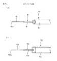
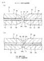
例えば、図20(a)に示すように、コネクタ付き光ファイバ12において、光ファイバ素線88は、その軸線方向端面88aに向かって先細り状に延びる面取り領域190を、軸線方向端面88aに隣接して備え、軸線方向端面88aをフェルール22の衝合端面46よりも外方へ僅かに突出させてフェルール22に取り付けられる。さらに、光ファイバ素線88は、フェルール22の素線保持孔48内で衝合端面46から所望長さの範囲に渡り、素線保持孔48に固定されない非固定領域192を、面取り領域190に隣接して備える。なお、光ファイバ素線88の非固定領域192以外の部分は、例えば図示のように接着剤194により素線保持孔48に固定できる。これに対し、コネクタ付き光ファイバ16において、光ファイバ素線168は、略平坦な軸線方向端面168aを有し、軸線方向端面168aをフェルール92の衝合端面136に対し実質的同一面上に配置してフェルール92に取り付けられる。さらに、光ファイバ素線168は、フェルール92の素線保持孔138内で衝合端面136から所望長さの範囲に渡り、素線保持孔138に固定されない非固定領域196を、軸線方向端面168aに隣接して備える。なお、光ファイバ素線168の非固定領域196以外の部分は、前述したように素線固定部材110によって固定したり、例えば図示のように接着剤198により素線保持孔138に固定したりすることができる。 For example, as shown in FIG. 20 (a), in the
このように構成されたコネクタ付き光ファイバ12、16に対し、前述したようにしてそれぞれの光コネクタ10、14同士を接続すると、圧縮コイルばね128の押圧力下で、両光ファイバ素線88、168の軸線方向端面88a、168aが互いに突き合わされる。このとき図20(b)に示すように、押圧力により、各フェルール22、92の素線保持孔48、138内で、光ファイバ素線88、168の非固定領域192、196が軸線方向へ圧縮されて、軸線方向端面88a、168a同士が強固に突き合わされるとともに、最終的に両フェルール22、92の衝合端面46、136が互いに衝合される。 When the respective
上記した突き合わせ接続形態によれば、フェルール22、92の衝合端面46、136に対して光ファイバ素線88、168の軸線方向端面88a、168aを高精度に(例えば0.1μmオーダで)位置決めする必要が無くなる。すなわち、光ファイバ素線88の軸線方向端面88aをフェルール22の衝合端面46から適当に(例えば数μm)突出させた状態で、光ファイバ素線88の後方領域を例えば素線保持孔48に接着剤194により固定しておけば、上記したように光ファイバ素線88、168の軸線方向端面88a、168a同士を強固に確実に突き合わせることができる。この程度の位置決め精度は、顕微鏡等の適当な道具を使用すれば、工事現場で手作業により達成できる。しかもこのとき、押圧力は両光ファイバ素線88、168の非固定領域192、196に分散して加わるので、軸線方向端面88a、168aの近傍領域への応力集中が回避され、接続後の光ファイバ素線88、168における光学特性の劣化が防止される。なお、他方の光ファイバ素線168の軸線方向端面168aは、同様にフェルール92の衝合端面136から適当に(例えば数μm)突出させた状態で、光ファイバ素線168の後方領域を例えば素線保持孔138に接着剤198により固定した後、光ファイバ素線168の突出部分を手作業で研磨することにより、衝合端面136に対し容易に同一平面化できる。 According to the butt connection form described above, the axial end surfaces 88a and 168a of the
また、上記した突き合わせ接続形態によれば、光ファイバ素線88、168の軸線方向端面88a、168aを軸線に対して正確に直角方向へ延びる鏡面として形成する必要が無くなる。例えば図21に示すように、各光ファイバ素線88、168の軸線方向端面88a、168aが軸線に対し僅かに傾斜して延びる場合であっても、一方の光ファイバ素線88に設けた面取り領域190が、双方のクラッド88b、168b同士の衝突位置をコア88c、168cに接近させるように作用する(図21(a))。その結果、コア88c、168cの間の隙間を可及的に削減することができ、以って接続損失を可及的に低減することができる。これに対し、いずれの光ファイバ素線88、168も面取り領域を有しない場合は、双方のクラッド88b、168b同士が外周付近で衝突する可能性が有り、その場合にはコア88c、168c間の隙間が増加して接続損失が増大する危惧が生じる(図21(b))。なお、光ファイバ素線88、168の軸線に対し適当に傾斜した軸線方向端面88a、168aは、一般的な光ファイバ切断工具を用いた劈開作用により、比較的容易に鏡面状に形成できる。 Further, according to the above-described butt connection form, it is not necessary to form the axial end faces 88a and 168a of the
さらに上記構成によれば、光ファイバ素線88、168の前述した傾斜端面88a、168aを、例えば直交端面に対する傾斜角度が8度程度となるように意図的に形成することもできる。このような傾斜角度を有する軸線方向端面88a、168aは、光の反射減衰量を削減する効果を奏する。なお、光ファイバ素線88、168の傾斜端面88a、168aは、フェルール22、92の衝合端面46、136を予め所望傾斜角度に成形しておき、光ファイバ素線88、168の軸線方向端面88a、168aを衝合端面46、136から適当に突出させて素線保持孔48、138に対し固定的に配置した後、光ファイバ素線88、168の突出部分を衝合端面46、136に沿うように手作業で研磨することにより、比較的容易に形成できる。 Furthermore, according to the above configuration, the above-described inclined end faces 88a and 168a of the
このように、本発明に係る光ファイバ素線の突き合わせ接続形態を採用すれば、屋内配線される光伝送路にコネクタ付き光ファイバ12、16を使用する目的で、工事現場でコネクタ装着作業を実施することが必要となる場合にも、直交鏡面状の軸線方向端面88a、168aを光ファイバ素線88、186に形成したりそれら軸線方向端面88a、168aの高精度の位置決めを要したりすることなく、接続損失を可及的に抑制した状態で光ファイバ素線88、186を相互接続することができる。 As described above, when the optical fiber butt connection form according to the present invention is adopted, the connector mounting work is performed on the construction site for the purpose of using the
上記した本発明に係る光ファイバ素線の突き合わせ接続形態は、一対のコネクタ付き光ファイバの少なくとも一方の光ファイバ素線に、対応のフェルールの素線保持孔内で衝合端面から所望長さの範囲に渡り素線保持孔に固定されない非固定領域を設けた上で、(1)少なくとも一方の光ファイバ素線に、軸線方向端面に向かって先細り状に延びる面取り領域を、軸線方向端面に隣接して形成すること、及び(2)少なくとも一方の光ファイバ素線の軸線方向端面を、対応のフェルールの衝合端面よりも外方へ突出させることの、いずれか一方又は双方の要件を満たせば良い。ここで要件(2)について、他方の光ファイバ素線を、その軸線方向端面がフェルールの素線保持孔内に引き込まれた位置に配置する場合は、両光ファイバ素線の端面突出量(引込量はマイナス符号)の和が零以上となるようにすれば良い。なお、図示実施形態におけるように、工場で組み立てることが一般的なコネクタ付き光ファイバにこれら要件を適用すれば、工事現場で組み立てることが一般的な相手方のコネクタ付き光ファイバを通常の単純な構成とすることができる。 The above-described butt connection form of the optical fiber according to the present invention is such that at least one optical fiber of the pair of optical fibers with connectors has a desired length from the abutting end face within the corresponding fiber holding hole of the ferrule. After providing a non-fixed region that is not fixed to the strand holding hole over the range, (1) a chamfered region that extends in a tapered manner toward the axial end surface is adjacent to at least one of the optical fiber strands. And (2) the axial end face of at least one of the optical fiber strands protrudes outward from the abutting end face of the corresponding ferrule, if one or both of the requirements are satisfied good. Here, for requirement (2), when the other end of the optical fiber is disposed at a position where its axial end face is drawn into the ferrule element holding hole, the end face protrusion amount (retraction) of both optical fiber elements The sum of the quantities (minus sign) may be zero or more. As shown in the illustrated embodiment, if these requirements are applied to an optical fiber with a connector that is generally assembled at a factory, the optical fiber with a connector of the other party that is generally assembled at a construction site is an ordinary simple configuration. It can be.
上記構成において、圧力下での光ファイバ素線同士の突き合わせ接続の完了時に、両フェルールの衝合端面が互いに密接しない場合には、光ファイバ素線自体の弾性によって安定した突き合わせ接続状態が得られていると考えられるので、圧縮コイルばね等の付勢手段を省略することもできる。また前述したように、少なくとも一方の光ファイバ素線を、対応のフェルールの素線保持孔の全体に渡って固定せず、例えばフェルールの外部に設置される機械的固定構造により光ファイバ素線をフェルールに対し固定的に支持する構成とすることもできる。 In the above configuration, when the abutting end faces of the two ferrules are not in close contact with each other when the butt connection between the optical fiber strands under pressure is completed, a stable butt connection state can be obtained due to the elasticity of the optical fiber strands themselves. Therefore, an urging means such as a compression coil spring can be omitted. Further, as described above, at least one of the optical fiber strands is not fixed over the entire wire holding hole of the corresponding ferrule. For example, the optical fiber strand is not fixed by a mechanical fixing structure installed outside the ferrule. It can also be set as the structure fixedly supported with respect to a ferrule.
上記した本発明に係る光ファイバ素線の突き合わせ接続形態は、以下の各ステップを実施することにより達成できる。すなわち、(A)衝合端面と、衝合端面に開口し、光ファイバ素線を固定的に収容する素線保持孔とをそれぞれに有する一対のフェルールを用意し、(B)一対の光ファイバ素線の少なくとも一方に、軸線方向端面に向かって先細り状に延びる面取り領域を、軸線方向端面に隣接して形成し、(C)一対の光ファイバ素線を一対のフェルールの素線保持孔にそれぞれ挿通して、少なくとも一方の光ファイバ素線の軸線方向端面を対応のフェルールの衝合端面よりも外方へ突出させるとともに、少なくとも一方の光ファイバ素線に対応のフェルールの素線保持孔内で衝合端面から所望長さの範囲に渡り素線保持孔に固定されない非固定領域を設け、(D)一対のフェルールを、それぞれの素線保持孔が互いに一直線に整列する整合位置に配置して、圧力下で、一対の光ファイバ素線の軸線方向端面同士を突き合わせる。 The above-described butt connection form of the optical fiber according to the present invention can be achieved by performing the following steps. That is, (A) a pair of ferrules each having an abutting end face and a strand holding hole that is open to the abutting end face and fixedly accommodates the optical fiber strand are prepared, and (B) a pair of optical fibers A chamfered region extending in a taper shape toward the axial end surface is formed adjacent to the axial end surface on at least one of the strands, and (C) the pair of optical fiber strands is used as the strand holding hole of the pair of ferrules. Each is inserted so that the axial end surface of at least one of the optical fiber strands protrudes outward from the abutting end surface of the corresponding ferrule, and in the ferrule strand holding hole of the at least one optical fiber strand The non-fixed area that is not fixed to the strand holding hole is provided over the range of the desired length from the abutting end face, and (D) the pair of ferrules are arranged at the alignment positions where the respective strand holding holes are aligned with each other. , Under pressure, matching the axial end faces of the pair of optical fibers.
本発明は、光ファイバの接続技術であって、例えば屋内配線される光伝送路における着脱自在な光接続部のように、外形寸法が制約され、しかも優れた現場施工性及び保全性が要求される用途に、極めて好適に適用できる。 The present invention is an optical fiber connection technique, and is required to have excellent on-site workability and maintainability, for example, with a limited external dimension like a detachable optical connection part in an optical transmission line wired indoors. The present invention can be applied to a very suitable application.
10、14…光コネクタ
12、16…コネクタ付き光ファイバ
18…光ファイバ接続装置
20、90…本体
22、92…フェルール
24…整列スリーブ部材
26…プラグハウジング
28…ブーツ
38、134…ラッチレバー
46、136…衝合端面
48、138…素線保持孔
50…割りスリーブ
52…スリーブホルダ
54…可動シャッタ
58…空洞部
80、160…光ファイバ心線
82…光ファイバコード
88、168…光ファイバ素線
88a、168a…軸線方向端面
94…保持部
96…ソケットブロック
98…ソケットハウジング
110…素線固定部材
112…作動部材
128…圧縮コイルばね
140…保持部材
148a…心線ガイド面
152…保持溝
162…光ファイバケーブル
170…アダプタ
186…ドア
190…面取り領域
192、196…非固定領域DESCRIPTION OF
Claims (12)
Translated fromJapanese軸線方向両端に開口を有する筒状の空洞部を備えた整列スリーブ部材であって、該空洞部の一部分に、前記衝合端面に隣接する前記フェルールの任意長さ部分を受容して、該フェルールに対し予め定めた位置に支持される整列スリーブ部材を具備し、
前記整列スリーブ部材は、前記本体の外側にプラグ状に突出する相手コネクタ嵌合部を有すること、
を特徴とする光コネクタ。In a plug-type optical connector comprising a main body and a ferrule installed on the main body and having an abutting end surface,
An alignment sleeve member having cylindrical cavities having openings at both ends in the axial direction, wherein an arbitrary length portion of the ferrule adjacent to the abutting end surface is received in a part of the cavities, and the ferrule An alignment sleeve member supported at a predetermined position with respect to
The alignment sleeve member has a mating connector fitting portion protruding in a plug shape outside the main body;
Optical connector characterized by.
軸線方向両端に開口を有する筒状の空洞部を備えた整列スリーブ部材であって、該空洞部の一部分に、前記衝合端面に隣接する前記フェルールの任意長さ部分を受容して、該フェルールに対し予め定めた位置に支持される整列スリーブ部材を具備し、
前記整列スリーブ部材は、前記空洞部に受動的変位可能に設置される可動シャッタを備え、該可動シャッタは、該空洞部の一方の前記開口から受容した前記フェルールと他方の前記開口との間で該空洞部内に突出して、該フェルールを通して放出される光を遮断する位置に配置されること、
を特徴とする光コネクタ。In an optical connector comprising a main body and a ferrule installed on the main body and having an abutting end surface,
An alignment sleeve member having cylindrical cavities having openings at both ends in the axial direction, wherein an arbitrary length portion of the ferrule adjacent to the abutting end surface is received in a part of the cavities, and the ferrule An alignment sleeve member supported at a predetermined position with respect to
The alignment sleeve member includes a movable shutter disposed in the cavity so as to be passively displaceable, and the movable shutter is disposed between the ferrule received from one of the openings of the cavity and the other of the openings. Projecting into the cavity and being disposed at a position to block light emitted through the ferrule;
Optical connector characterized by.
前記フェルールの前記衝合端面とは反対側の端面から予め定めた距離だけ離隔して前記本体に設置される保持部を具備し、
前記フェルールは、光ファイバ心線の先端に取り付けられた状態で、前記本体上で前記素線保持孔に略平行な方向へ変位でき、
前記保持部は、前記フェルールの前記素線保持孔の延長方向に対し傾斜した方向へ延設される保持溝を備え、該フェルールと該保持溝との間で、前記本体上での該フェルールの位置に関わらず、光ファイバ心線を予め定めた最小曲げ半径以上の曲げ半径で撓曲させること、
を特徴とする光コネクタ。In an optical connector comprising a main body, and a ferrule that is installed in the main body and has an abutting end surface and a wire holding hole that opens in the abutting end surface,
A holding portion installed in the main body at a predetermined distance from the end surface opposite to the abutting end surface of the ferrule;
The ferrule can be displaced in a direction substantially parallel to the strand holding hole on the main body in a state where the ferrule is attached to the tip of an optical fiber core wire,
The holding portion includes a holding groove extending in a direction inclined with respect to an extension direction of the wire holding hole of the ferrule, and the ferrule on the main body is interposed between the ferrule and the holding groove. Bending the optical fiber core with a bend radius greater than a predetermined minimum bend radius, regardless of position,
Optical connector characterized by.
前記フェルールは、衝合端面と、該衝合端面に開口し、前記光ファイバ心線が有する光ファイバ素線を収容する素線保持孔とを備え、
前記光ファイバ心線は、前記光ファイバ素線の軸線方向端面に隣接して形成され、該軸線方向端面に向かって先細り状に延びる面取り領域と、該面取り領域に隣接して形成され、該フェルールの前記素線保持孔内で該衝合端面から所望長さの範囲に渡り該素線保持孔に固定されない非固定領域とを有すること、
を特徴とするコネクタ付き光ファイバ。In an optical fiber with a connector comprising an optical connector having a ferrule and an optical fiber core wire having the ferrule attached to the tip,
The ferrule includes an abutting end surface, and a strand holding hole that opens to the abutting end surface and accommodates an optical fiber strand that the optical fiber core wire has,
The optical fiber core wire is formed adjacent to the axial end face of the optical fiber strand, is formed to be tapered toward the axial end face, is formed adjacent to the chamfer area, and the ferrule. A non-fixed region that is not fixed to the strand holding hole over a range of a desired length from the abutting end surface in the strand holding hole of
An optical fiber with a connector.
前記フェルールは、衝合端面と、該衝合端面に開口し、前記光ファイバ心線が有する光ファイバ素線を収容する素線保持孔とを備え、
前記光ファイバ心線は、前記光ファイバ素線の軸線方向端面を前記フェルールの前記衝合端面よりも外方へ突出させて該フェルールに取り付けられるとともに、該フェルールの前記素線保持孔内で該衝合端面から所望長さの範囲に渡り該素線保持孔に固定されない非固定領域を有すること、
を特徴とするコネクタ付き光ファイバ。In an optical fiber with a connector comprising an optical connector having a ferrule and an optical fiber core wire having the ferrule attached to the tip,
The ferrule includes an abutting end surface, and a strand holding hole that opens to the abutting end surface and accommodates an optical fiber strand that the optical fiber core wire has,
The optical fiber core wire is attached to the ferrule with an axial end surface of the optical fiber strand protruding outward from the abutting end surface of the ferrule, and the optical fiber core wire is attached to the ferrule in the strand holding hole. Having a non-fixed region that is not fixed to the wire holding hole over a range of a desired length from the abutting end surface;
An optical fiber with a connector.
衝合端面と、該衝合端面に開口し、光ファイバ素線を収容する素線保持孔とをそれぞれに有する一対のフェルールを用意し、
一対の光ファイバ素線の少なくとも一方に、軸線方向端面に向かって先細り状に延びる面取り領域を、該軸線方向端面に隣接して形成し、
前記一対の光ファイバ素線を前記一対のフェルールの前記素線保持孔にそれぞれ挿通して、少なくとも一方の該光ファイバ素線の前記軸線方向端面を対応の該フェルールの前記衝合端面よりも外方へ突出させるとともに、少なくとも一方の該光ファイバ素線に対応の該フェルールの該素線保持孔内で該衝合端面から所望長さの範囲に渡り該素線保持孔に固定されない非固定領域を設け、
前記一対のフェルールを、それぞれの前記素線保持孔が互いに一直線に整列する整合位置に配置して、圧力下で、前記一対の光ファイバ素線の前記軸線方向端面同士を突き合わせること、
を特徴とする光ファイバ接続方法。An optical fiber connection method for interconnecting a pair of optical fiber strands in a face-to-face state,
A pair of ferrules each having an abutting end surface and an element holding hole that opens to the abutting end surface and accommodates an optical fiber element are prepared,
A chamfering region extending in a tapered manner toward the axial end surface is formed adjacent to the axial end surface on at least one of the pair of optical fiber strands,
The pair of optical fiber strands are respectively inserted into the strand holding holes of the pair of ferrules, and the axial end surfaces of at least one of the optical fiber strands are outside the abutting end surfaces of the corresponding ferrules. And a non-fixed region that is not fixed to the strand holding hole over a range of a desired length from the abutting end surface in the strand holding hole of the ferrule corresponding to at least one of the optical fiber strands Provided,
Placing the pair of ferrules in alignment positions where the strand holding holes are aligned with each other, and abutting the axial end faces of the pair of optical fiber strands under pressure;
An optical fiber connection method.
Priority Applications (11)
| Application Number | Priority Date | Filing Date | Title |
|---|---|---|---|
| JP2003428071AJP2005189332A (en) | 2003-12-24 | 2003-12-24 | Optical connector, optical fiber with connector, optical fiber connecting apparatus and method for connecting optical fiber |
| CNA2009101379103ACN101556357A (en) | 2003-12-24 | 2004-07-23 | Optical connector, optical fiber with connector and optical fiber connection method |
| US10/897,741US7331718B2 (en) | 2003-12-24 | 2004-07-23 | Optical connector, optical fiber with connector, optical fiber connecting device, and optical fiber connection method |
| KR1020067012580AKR101085319B1 (en) | 2003-12-24 | 2004-07-23 | Optical connector, optical fiber with connector, optical fiber connection device, and optical fiber connection method |
| PCT/US2004/023923WO2005069051A1 (en) | 2003-12-24 | 2004-07-23 | Optical connector, optical fiber with connector, optical fiber connecting device, and optical fiber connection method |
| CNB2004800388030ACN100504475C (en) | 2003-12-24 | 2004-07-23 | Optical connector, optical fiber having connector, optical fiber connecting device, and optical fiber connecting method |
| EP04786103AEP1697779A1 (en) | 2003-12-24 | 2004-07-23 | Optical connector, optical fiber with connector, optical fiber connecting device, and optical fiber connection method |
| JP2006546956AJP2007517255A (en) | 2003-12-24 | 2004-07-23 | Optical connector, optical fiber with connector, optical fiber connection device, and optical fiber connection method |
| US12/032,918US7942589B2 (en) | 2003-12-24 | 2008-02-18 | Optical connector, optical fiber with connector, optical fiber connecting device, and optical fiber connection method |
| US12/032,904US20090080839A1 (en) | 2003-12-24 | 2008-02-18 | Optical connector, optical fiber with connector, optical fiber connecting device, and optical fiber connection method |
| JP2010163299AJP5108063B2 (en) | 2003-12-24 | 2010-07-20 | Optical connector, optical fiber with connector, and optical fiber connecting device |
Applications Claiming Priority (1)
| Application Number | Priority Date | Filing Date | Title |
|---|---|---|---|
| JP2003428071AJP2005189332A (en) | 2003-12-24 | 2003-12-24 | Optical connector, optical fiber with connector, optical fiber connecting apparatus and method for connecting optical fiber |
Publications (1)
| Publication Number | Publication Date |
|---|---|
| JP2005189332Atrue JP2005189332A (en) | 2005-07-14 |
Family
ID=34697502
Family Applications (3)
| Application Number | Title | Priority Date | Filing Date |
|---|---|---|---|
| JP2003428071APendingJP2005189332A (en) | 2003-12-24 | 2003-12-24 | Optical connector, optical fiber with connector, optical fiber connecting apparatus and method for connecting optical fiber |
| JP2006546956APendingJP2007517255A (en) | 2003-12-24 | 2004-07-23 | Optical connector, optical fiber with connector, optical fiber connection device, and optical fiber connection method |
| JP2010163299AExpired - Fee RelatedJP5108063B2 (en) | 2003-12-24 | 2010-07-20 | Optical connector, optical fiber with connector, and optical fiber connecting device |
Family Applications After (2)
| Application Number | Title | Priority Date | Filing Date |
|---|---|---|---|
| JP2006546956APendingJP2007517255A (en) | 2003-12-24 | 2004-07-23 | Optical connector, optical fiber with connector, optical fiber connection device, and optical fiber connection method |
| JP2010163299AExpired - Fee RelatedJP5108063B2 (en) | 2003-12-24 | 2010-07-20 | Optical connector, optical fiber with connector, and optical fiber connecting device |
Country Status (6)
| Country | Link |
|---|---|
| US (3) | US7331718B2 (en) |
| EP (1) | EP1697779A1 (en) |
| JP (3) | JP2005189332A (en) |
| KR (1) | KR101085319B1 (en) |
| CN (2) | CN101556357A (en) |
| WO (1) | WO2005069051A1 (en) |
Cited By (8)
| Publication number | Priority date | Publication date | Assignee | Title |
|---|---|---|---|---|
| JP2008090069A (en)* | 2006-10-03 | 2008-04-17 | Sanwa Denki Kogyo Co Ltd | Optical connector plug having light shielding function |
| JP2008116518A (en)* | 2006-11-01 | 2008-05-22 | Sanwa Denki Kogyo Co Ltd | Optical connector plug with optical shielding function |
| JP2008233450A (en)* | 2007-03-20 | 2008-10-02 | Sanwa Denki Kogyo Co Ltd | Hinge type right angle bending connector |
| JP2009092925A (en)* | 2007-10-09 | 2009-04-30 | Sumitomo Electric Ind Ltd | Optical connector |
| JP2009282177A (en)* | 2008-05-21 | 2009-12-03 | Sanwa Denki Kogyo Co Ltd | Bent boot for optical connector |
| WO2015162884A1 (en)* | 2014-04-21 | 2015-10-29 | オリンパス株式会社 | Connection adapter for optical fiber and endoscope device |
| WO2020075734A1 (en) | 2018-10-11 | 2020-04-16 | 株式会社フジクラ | Optical fiber cable |
| JP2022187127A (en)* | 2021-06-07 | 2022-12-19 | 矢崎総業株式会社 | optical connector |
Families Citing this family (155)
| Publication number | Priority date | Publication date | Assignee | Title |
|---|---|---|---|---|
| US5883995A (en) | 1997-05-20 | 1999-03-16 | Adc Telecommunications, Inc. | Fiber connector and adapter |
| JP4544928B2 (en)* | 2004-07-16 | 2010-09-15 | スリーエム イノベイティブ プロパティズ カンパニー | Optical connector and optical fiber connection system |
| JP4416591B2 (en)* | 2004-07-16 | 2010-02-17 | スリーエム イノベイティブ プロパティズ カンパニー | Optical connector and optical fiber connection system |
| JP4942327B2 (en)* | 2005-10-28 | 2012-05-30 | スリーエム イノベイティブ プロパティズ カンパニー | Optical connector |
| JP4660351B2 (en)* | 2005-10-31 | 2011-03-30 | スリーエム イノベイティブ プロパティズ カンパニー | Optical connector |
| EP2115508A1 (en) | 2007-02-16 | 2009-11-11 | 3M Innovative Properties Company | Remote grip optical fiber connector |
| US7775726B2 (en)* | 2007-02-16 | 2010-08-17 | 3M Innovative Properties Company | Remote grip optical fiber connector |
| JP2008216483A (en)* | 2007-03-01 | 2008-09-18 | Advanced Cable Systems Corp | Fiber optic cable and inserting method thereof |
| US7534050B2 (en)* | 2007-04-13 | 2009-05-19 | Adc Telecommunications, Inc. | Field terminatable fiber optic connector assembly |
| JP4806672B2 (en)* | 2007-10-22 | 2011-11-02 | 株式会社フジクラ | Optical connector |
| JP5313513B2 (en)* | 2008-02-04 | 2013-10-09 | スリーエム イノベイティブ プロパティズ カンパニー | Optical fiber cord holding device, holding method, and optical fiber connecting device |
| US8444326B2 (en)* | 2008-05-30 | 2013-05-21 | 3M Innovative Properties Company | Flexible optical coupling |
| US10718909B2 (en)* | 2008-07-29 | 2020-07-21 | Glenair, Inc. | Expanded beam fiber optic connection system |
| JP4788007B2 (en)* | 2008-08-06 | 2011-10-05 | Necアクセステクニカ株式会社 | Cable fixing structure |
| US11294136B2 (en) | 2008-08-29 | 2022-04-05 | Corning Optical Communications LLC | High density and bandwidth fiber optic apparatuses and related equipment and methods |
| US8452148B2 (en) | 2008-08-29 | 2013-05-28 | Corning Cable Systems Llc | Independently translatable modules and fiber optic equipment trays in fiber optic equipment |
| TW200921172A (en)* | 2008-12-11 | 2009-05-16 | Protai Photonic Co Ltd | Flexibly bended boot for optical fiber connector |
| US8348516B2 (en)* | 2009-02-10 | 2013-01-08 | Amphenol Corporation | High density front panel optical interconnect |
| EP2221932B1 (en) | 2009-02-24 | 2011-11-16 | CCS Technology Inc. | Holding device for a cable or an assembly for use with a cable |
| JP2010237330A (en)* | 2009-03-30 | 2010-10-21 | Furukawa Electric Co Ltd:The | Optical fiber connection structure |
| JP5497332B2 (en)* | 2009-05-14 | 2014-05-21 | スリーエム イノベイティブ プロパティズ カンパニー | Optical connector |
| US8699838B2 (en) | 2009-05-14 | 2014-04-15 | Ccs Technology, Inc. | Fiber optic furcation module |
| JP4863319B2 (en)* | 2009-05-19 | 2012-01-25 | 日本航空電子工業株式会社 | Optical connector |
| US9075216B2 (en) | 2009-05-21 | 2015-07-07 | Corning Cable Systems Llc | Fiber optic housings configured to accommodate fiber optic modules/cassettes and fiber optic panels, and related components and methods |
| US8201322B2 (en)* | 2009-05-29 | 2012-06-19 | Schratz Gary F | Fiber optic connector tooling device |
| JP2010277999A (en)* | 2009-06-01 | 2010-12-09 | Korea Electronics Telecommun | Dye-sensitized solar cell and manufacturing method thereof |
| EP2443497B1 (en) | 2009-06-19 | 2020-03-04 | Corning Cable Systems LLC | High density and bandwidth fiber optic apparatus |
| US8712206B2 (en)* | 2009-06-19 | 2014-04-29 | Corning Cable Systems Llc | High-density fiber optic modules and module housings and related equipment |
| CN101614846B (en)* | 2009-06-30 | 2011-01-19 | 宁波电业局 | Fiber core alignment device |
| US8152384B2 (en)* | 2009-10-15 | 2012-04-10 | Corning Cable Systems Llc | Push-pull fiber optic connectors and methods for making the same |
| US20110129185A1 (en)* | 2009-11-30 | 2011-06-02 | Lewallen C Paul | Articulated Strain Relief Boot on a Fiber Optic Module and Associated Methods |
| US8625950B2 (en) | 2009-12-18 | 2014-01-07 | Corning Cable Systems Llc | Rotary locking apparatus for fiber optic equipment trays and related methods |
| US8992099B2 (en) | 2010-02-04 | 2015-03-31 | Corning Cable Systems Llc | Optical interface cards, assemblies, and related methods, suited for installation and use in antenna system equipment |
| US8579518B2 (en)* | 2010-03-19 | 2013-11-12 | Corning Incorporated | Optical receptacles and systems and devices including optical receptacles |
| US8727636B2 (en)* | 2010-03-19 | 2014-05-20 | Corning Incorporated | Fiber optic interface device with positionable cleaning cover |
| US8913866B2 (en) | 2010-03-26 | 2014-12-16 | Corning Cable Systems Llc | Movable adapter panel |
| CA2796221C (en) | 2010-04-16 | 2018-02-13 | Ccs Technology, Inc. | Sealing and strain relief device for data cables |
| US9720195B2 (en) | 2010-04-30 | 2017-08-01 | Corning Optical Communications LLC | Apparatuses and related components and methods for attachment and release of fiber optic housings to and from an equipment rack |
| US8705926B2 (en) | 2010-04-30 | 2014-04-22 | Corning Optical Communications LLC | Fiber optic housings having a removable top, and related components and methods |
| US9632270B2 (en) | 2010-04-30 | 2017-04-25 | Corning Optical Communications LLC | Fiber optic housings configured for tool-less assembly, and related components and methods |
| US8660397B2 (en) | 2010-04-30 | 2014-02-25 | Corning Cable Systems Llc | Multi-layer module |
| US9075217B2 (en) | 2010-04-30 | 2015-07-07 | Corning Cable Systems Llc | Apparatuses and related components and methods for expanding capacity of fiber optic housings |
| US8879881B2 (en) | 2010-04-30 | 2014-11-04 | Corning Cable Systems Llc | Rotatable routing guide and assembly |
| US9519118B2 (en) | 2010-04-30 | 2016-12-13 | Corning Optical Communications LLC | Removable fiber management sections for fiber optic housings, and related components and methods |
| US8718436B2 (en) | 2010-08-30 | 2014-05-06 | Corning Cable Systems Llc | Methods, apparatuses for providing secure fiber optic connections |
| US9279951B2 (en) | 2010-10-27 | 2016-03-08 | Corning Cable Systems Llc | Fiber optic module for limited space applications having a partially sealed module sub-assembly |
| US9116324B2 (en) | 2010-10-29 | 2015-08-25 | Corning Cable Systems Llc | Stacked fiber optic modules and fiber optic equipment configured to support stacked fiber optic modules |
| US8662760B2 (en) | 2010-10-29 | 2014-03-04 | Corning Cable Systems Llc | Fiber optic connector employing optical fiber guide member |
| JP5755872B2 (en)* | 2010-11-30 | 2015-07-29 | スリーエム イノベイティブ プロパティズ カンパニー | Optical connector and method for manufacturing optical connector with cable |
| CA2819235C (en) | 2010-11-30 | 2018-01-16 | Corning Cable Systems Llc | Fiber device holder and strain relief device |
| WO2012106510A2 (en) | 2011-02-02 | 2012-08-09 | Corning Cable Systems Llc | Dense fiber optic connector assemblies and related connectors and cables suitable for establishing optical connections for optical backplanes in equipment racks |
| US8636425B2 (en) | 2011-03-15 | 2014-01-28 | Adc Telecommunications, Inc. | Fiber optic connector |
| US9008485B2 (en) | 2011-05-09 | 2015-04-14 | Corning Cable Systems Llc | Attachment mechanisms employed to attach a rear housing section to a fiber optic housing, and related assemblies and methods |
| US9188747B2 (en) | 2011-05-23 | 2015-11-17 | Senko Advanced Components, Inc. | True one piece housing fiber optic adapter |
| AU2012275598A1 (en) | 2011-06-30 | 2014-01-16 | Corning Optical Communications LLC | Fiber optic equipment assemblies employing non-U-width-sized housings and related methods |
| US8953924B2 (en) | 2011-09-02 | 2015-02-10 | Corning Cable Systems Llc | Removable strain relief brackets for securing fiber optic cables and/or optical fibers to fiber optic equipment, and related assemblies and methods |
| CN102313936A (en)* | 2011-09-07 | 2012-01-11 | 江苏宇特光电科技有限公司 | Inclination-angle-line-type fiber splicer capable of being opened and used repeatedly |
| KR101203509B1 (en)* | 2011-11-21 | 2012-11-21 | 박찬설 | Fiber optic connectors |
| US9038832B2 (en) | 2011-11-30 | 2015-05-26 | Corning Cable Systems Llc | Adapter panel support assembly |
| JP2015500516A (en)* | 2011-12-15 | 2015-01-05 | 矢崎総業株式会社 | Optical connector |
| WO2013177016A1 (en) | 2012-05-22 | 2013-11-28 | Adc Telecommunications, Inc. | Ruggedized fiber optic connector |
| JP6201222B2 (en) | 2012-06-26 | 2017-09-27 | ▲ホア▼▲ウェイ▼技術有限公司Huawei Technologies Co.,Ltd. | Optical fiber connector, optical fiber adapter, and optical fiber connector assembly |
| US9250409B2 (en) | 2012-07-02 | 2016-02-02 | Corning Cable Systems Llc | Fiber-optic-module trays and drawers for fiber-optic equipment |
| US8974124B2 (en) | 2012-08-16 | 2015-03-10 | Senko Advanced Components, Inc. | Fiber optic connector |
| US9042702B2 (en) | 2012-09-18 | 2015-05-26 | Corning Cable Systems Llc | Platforms and systems for fiber optic cable attachment |
| ES2551077T3 (en) | 2012-10-26 | 2015-11-16 | Ccs Technology, Inc. | Fiber optic management unit and fiber optic distribution device |
| US8985862B2 (en) | 2013-02-28 | 2015-03-24 | Corning Cable Systems Llc | High-density multi-fiber adapter housings |
| US9268103B2 (en) | 2013-05-10 | 2016-02-23 | Senko Advanced Components, Inc. | Interlockable fiber optic connector adaptors |
| US9360649B2 (en) | 2013-05-22 | 2016-06-07 | Senko Advanced Components, Inc. | Cable guide for fiber optic cables |
| JP5656099B1 (en)* | 2013-06-28 | 2015-01-21 | Toto株式会社 | Optical receptacle, ferrule and plug ferrule |
| WO2015047380A1 (en) | 2013-09-30 | 2015-04-02 | Hewlett-Packard Development Company, Lp | Optical blind-mate connector and adapter |
| US9618703B2 (en) | 2013-10-03 | 2017-04-11 | Senko Advanced Components, Inc. | Connector housing for securing an optical cable and methods of use and manufacture thereof |
| US9829646B2 (en)* | 2013-11-04 | 2017-11-28 | CommScope Connectivity Belgium BVBA | Fiber optic connector having an optical fiber that is axially moveable within a ferrule |
| JP5815657B2 (en)* | 2013-12-17 | 2015-11-17 | スリーエム イノベイティブ プロパティズ カンパニー | Optical connector |
| US9477049B2 (en) | 2013-12-20 | 2016-10-25 | Senko Advanced Components, Inc. | Lockable connectors and connection assemblies |
| CN104777561B (en)* | 2014-01-14 | 2018-03-23 | 泰科电子(上海)有限公司 | Calibration system and method, fiber stub component and manufacture method, the joints of optical fibre |
| US9535230B2 (en) | 2014-01-31 | 2017-01-03 | Senko Advanced Components, Inc. | Integrated fiber optic cable fan-out connector |
| CN103823278B (en)* | 2014-02-20 | 2016-05-04 | 深圳日海通讯技术股份有限公司 | A kind of joints of optical fibre and manufacture method thereof |
| EP3132296B1 (en)* | 2014-04-17 | 2023-01-04 | Boston Scientific Scimed, Inc. | Self-cleaning optical connector |
| US9297964B2 (en) | 2014-04-18 | 2016-03-29 | Senko Advanced Components, Inc. | Optical fiber connector assembly |
| US9274287B2 (en) | 2014-05-13 | 2016-03-01 | Senko Advanced Components, Inc. | Optical fiber connector and ferrule |
| US9618702B2 (en) | 2014-06-09 | 2017-04-11 | Senko Advanced Components, Inc. | Reduced-profile data transmission element connectors, adapters, and connection assemblies thereof |
| US9599778B2 (en) | 2014-10-22 | 2017-03-21 | Senko Advanced Components, Inc. | Latching connector with remote release |
| US10345526B2 (en)* | 2014-12-14 | 2019-07-09 | Telescent Inc. | High reliability robotic cross-connect systems |
| US9494745B2 (en) | 2015-01-16 | 2016-11-15 | Senko Advanced Components, Inc. | Sealable communication cable connection assemblies |
| US9658409B2 (en) | 2015-03-03 | 2017-05-23 | Senko Advanced Components, Inc. | Optical fiber connector with changeable polarity |
| US9684139B2 (en) | 2015-05-29 | 2017-06-20 | Senko Advanced Components, Inc. | Optical fiber connector with changeable gender |
| KR102419396B1 (en)* | 2015-09-25 | 2022-07-08 | 엘에스전선 주식회사 | Joint for optical fiber and power line composite cable |
| CN105278051B (en)* | 2015-11-27 | 2017-05-31 | 宁波市樱铭电子科技有限公司 | A kind of fiber core docking structure |
| CN105301708B (en)* | 2015-11-27 | 2017-05-31 | 宁波市樱铭电子科技有限公司 | A kind of fiber core docking facilities |
| CN105301707B (en)* | 2015-11-27 | 2017-05-31 | 宁波市樱铭电子科技有限公司 | A kind of fiber core docking facilities |
| EP3419514B1 (en) | 2016-02-23 | 2023-08-23 | Boston Scientific Scimed, Inc. | Pressure sensing guidewire systems including an optical connector cable |
| US9885843B2 (en)* | 2016-05-31 | 2018-02-06 | Corning Optical Communications LLC | Forming a fiber bulge in an optical fiber end for positioning the optical fiber in a ferrule bore |
| US9726830B1 (en) | 2016-06-28 | 2017-08-08 | Senko Advanced Components, Inc. | Connector and adapter system for two-fiber mechanical transfer type ferrule |
| US10228521B2 (en) | 2016-12-05 | 2019-03-12 | Senko Advanced Components, Inc. | Narrow width adapters and connectors with modular latching arm |
| US10078188B1 (en) | 2016-12-05 | 2018-09-18 | Senko Advanced Components, Inc. | Springless push/pull fiber optic connector |
| US10725248B2 (en) | 2017-01-30 | 2020-07-28 | Senko Advanced Components, Inc. | Fiber optic receptacle with integrated device therein incorporating a behind-the-wall fiber optic receptacle |
| CN110249248B (en) | 2017-01-30 | 2021-07-27 | 扇港元器件股份有限公司 | Optical connectors with reversible polarity |
| US11333836B2 (en) | 2017-01-30 | 2022-05-17 | Senko Advanced Components, Inc. | Adapter for optical connectors |
| US10416394B2 (en) | 2017-01-30 | 2019-09-17 | Senko Advanced Components, Inc. | Fiber optic receptacle with integrated device therein |
| US10444444B2 (en) | 2017-01-30 | 2019-10-15 | Senko Advanced Components, Inc. | Remote release tab connector assembly |
| US10185100B2 (en) | 2017-01-30 | 2019-01-22 | Senko Advanced Components, Inc | Modular connector and adapter assembly using a removable anchor device |
| US10820440B2 (en)* | 2017-03-02 | 2020-10-27 | Cisco Technology, Inc. | Minimal touch bracket for cable routing with rack mounted devices |
| US10575429B2 (en)* | 2017-04-04 | 2020-02-25 | Cisco Technology, Inc. | Adjustable cable management slide and direction control for optimized routing |
| US10209461B2 (en) | 2017-04-07 | 2019-02-19 | Senko Advanced Components | Behind the wall optical connector with reduced components |
| US10989884B2 (en) | 2017-04-07 | 2021-04-27 | Senko Advanced Components, Inc. | Behind the wall optical connector with reduced components |
| US10754098B2 (en) | 2017-04-07 | 2020-08-25 | Senko Advanced Components, Inc. | Behind the wall optical connector with reduced components |
| US10359583B2 (en) | 2017-04-07 | 2019-07-23 | Senko Advanced Components, Inc. | Behind the wall optical connector with reduced components |
| US10718910B2 (en) | 2017-05-03 | 2020-07-21 | Senko Advanced Components, Inc | Field terminated ruggedized fiber optic connector system |
| US10401576B2 (en) | 2017-05-10 | 2019-09-03 | Senko Advanced Components, Inc. | MPO micro-latch-lock connector |
| US10146016B1 (en) | 2017-05-10 | 2018-12-04 | Senko Advanced Components, Inc | MPO micro-latchlock connector |
| US10295759B2 (en) | 2017-05-18 | 2019-05-21 | Senko Advanced Components, Inc. | Optical connector with forward-biasing projections |
| US10359576B2 (en) | 2017-06-15 | 2019-07-23 | Senko Advanced Components, Inc. | SC low profile connector with optional boot |
| US11822133B2 (en) | 2017-07-14 | 2023-11-21 | Senko Advanced Components, Inc. | Ultra-small form factor optical connector and adapter |
| US10281669B2 (en) | 2017-07-14 | 2019-05-07 | Senko Advance Components, Inc. | Ultra-small form factor optical connectors |
| US12001064B2 (en) | 2017-07-14 | 2024-06-04 | Senko Advanced Components, Inc. | Small form factor fiber optic connector with multi-purpose boot |
| US10718911B2 (en) | 2017-08-24 | 2020-07-21 | Senko Advanced Components, Inc. | Ultra-small form factor optical connectors using a push-pull boot receptacle release |
| CN116327157B (en) | 2017-08-03 | 2025-09-30 | 波士顿科学国际有限公司 | Methods for assessing fractional flow reserve |
| US10641972B2 (en) | 2017-08-17 | 2020-05-05 | Senko Advanced Components, Inc | Anti-jam alignment sleeve holder or connector housing for a ferrule assembly |
| US10444442B2 (en) | 2017-11-03 | 2019-10-15 | Senko Advanced Components, Inc. | MPO optical fiber connector |
| US11002923B2 (en) | 2017-11-21 | 2021-05-11 | Senko Advanced Components, Inc. | Fiber optic connector with cable boot release having a two-piece clip assembly |
| US11016250B2 (en)* | 2017-12-19 | 2021-05-25 | Us Conec, Ltd. | Mini duplex connector with push-pull polarity mechanism, carrier, and rail-receiving crimp body |
| US11311196B2 (en) | 2018-02-23 | 2022-04-26 | Boston Scientific Scimed, Inc. | Methods for assessing a vessel with sequential physiological measurements |
| WO2019183070A2 (en) | 2018-03-19 | 2019-09-26 | Senko Advanced Components, Inc. | Removal tool for removing a plural of micro optical connectors from an adapter interface |
| EP3768156B1 (en) | 2018-03-23 | 2023-09-20 | Boston Scientific Scimed, Inc. | Medical device with pressure sensor |
| EP3776038B1 (en) | 2018-03-28 | 2024-07-03 | Senko Advanced Components Inc. | Small form factor fiber optic connector with multi-purpose boot |
| WO2019195721A1 (en) | 2018-04-06 | 2019-10-10 | Boston Scientific Scimed, Inc. | Medical device with pressure sensor |
| CN119564167A (en) | 2018-04-18 | 2025-03-07 | 波士顿科学国际有限公司 | System for vascular assessment using continuous physiological measurements |
| US11041993B2 (en) | 2018-04-19 | 2021-06-22 | Senko Advanced Components, Inc. | Fiber optic adapter with removable insert for polarity change and removal tool for the same |
| US10921528B2 (en) | 2018-06-07 | 2021-02-16 | Senko Advanced Components, Inc. | Dual spring multi-fiber optic connector |
| CN112088327A (en) | 2018-07-15 | 2020-12-15 | 扇港元器件股份有限公司 | Subminiature Optical Connectors and Adapters |
| US10444441B1 (en) | 2018-08-10 | 2019-10-15 | Senko Advanced Components, Inc. | Pivotable housing for a fiber optic connector |
| US11073664B2 (en) | 2018-08-13 | 2021-07-27 | Senko Advanced Components, Inc. | Cable boot assembly for releasing fiber optic connector from a receptacle |
| WO2020055440A1 (en) | 2018-09-12 | 2020-03-19 | Senko Advanced Componetns, Inc. | Lc type connector with clip-on push/pull tab for releasing connector from a receptacle using a cable boot |
| US10921530B2 (en) | 2018-09-12 | 2021-02-16 | Senko Advanced Components, Inc. | LC type connector with push/pull assembly for releasing connector from a receptacle using a cable boot |
| US10921531B2 (en) | 2018-09-12 | 2021-02-16 | Senko Advanced Components, Inc. | LC type connector with push/pull assembly for releasing connector from a receptacle using a cable boot |
| CN110941054B (en)* | 2018-09-25 | 2022-05-31 | 韩国奥特伦株式会社 | On-site assembled optical fiber connector |
| US11806831B2 (en) | 2018-11-21 | 2023-11-07 | Senko Advanced Components, Inc. | Fixture and method for polishing fiber optic connector ferrules |
| US11175464B2 (en) | 2018-11-25 | 2021-11-16 | Senko Advanced Components, Inc. | Open ended spring body for use in an optical fiber connector |
| US12038613B2 (en) | 2019-03-28 | 2024-07-16 | Senko Advanced Components, Inc. | Behind-the-wall optical connector and assembly of the same |
| US11579379B2 (en) | 2019-03-28 | 2023-02-14 | Senko Advanced Components, Inc. | Fiber optic adapter assembly |
| US11340406B2 (en) | 2019-04-19 | 2022-05-24 | Senko Advanced Components, Inc. | Small form factor fiber optic connector with resilient latching mechanism for securing within a hook-less receptacle |
| US11112015B2 (en)* | 2019-06-06 | 2021-09-07 | Robert Bosch Llc | Fluid valve assembly including seal having retention features |
| WO2020252355A1 (en) | 2019-06-13 | 2020-12-17 | Senko Advanced Components, Inc | Lever actuated latch arm for releasing a fiber optic connector from a receptacle port and method of use |
| CN114600018B (en) | 2019-07-23 | 2024-04-09 | 扇港元器件有限公司 | Ultra-small receptacle for receiving a fiber optic connector opposite a ferrule assembly |
| CN110286458A (en)* | 2019-07-24 | 2019-09-27 | 嘉兴旭锐电子科技有限公司 | A reconfigurable optical positioning system and method using a block structure |
| US11353664B1 (en) | 2019-08-21 | 2022-06-07 | Senko Advanced Components, Inc. | Fiber optic connector |
| WO2021097304A1 (en) | 2019-11-13 | 2021-05-20 | Senko Advanced Components, Inc. | Fiber optic connector |
| US11796742B1 (en)* | 2020-04-24 | 2023-10-24 | Carlisle Interconnect Technologies, Inc. | Protective seal assembly for connector mating interface |
| CN114839725A (en)* | 2021-02-01 | 2022-08-02 | 东莞云晖光电有限公司 | Optical fiber end fixing structure and optical fiber end fixing method |
| US12087000B2 (en) | 2021-03-05 | 2024-09-10 | Boston Scientific Scimed, Inc. | Systems and methods for vascular image co-registration |
| US11899245B2 (en)* | 2021-07-26 | 2024-02-13 | Te Connectivity Solutions Gmbh | Optical receptacle connector for an optical communication system |
| US11906801B2 (en)* | 2021-07-26 | 2024-02-20 | Te Connectivity Solutions Gmbh | Optical receptacle connector for an optical communication system |
| CN116125602B (en)* | 2022-12-27 | 2024-04-05 | 镭神技术(深圳)有限公司 | Optical fiber connector and optical signal transmission device |
| GB2637736A (en)* | 2024-02-01 | 2025-08-06 | Ridgemount Tech Limited | Fibre optic connector |
Family Cites Families (69)
| Publication number | Priority date | Publication date | Assignee | Title |
|---|---|---|---|---|
| FR2464490A1 (en) | 1979-08-31 | 1981-03-06 | Deutsch Co | Two-part optical fibre connector - with female part contg. spring loaded insert in which fibre can freely slide |
| JPS5790407A (en)* | 1980-11-22 | 1982-06-05 | Shinji Tanaka | Injection apparatus for pressurized fluid |
| JPH0322725Y2 (en) | 1980-11-25 | 1991-05-17 | ||
| US4611887A (en)* | 1983-02-24 | 1986-09-16 | Amp Incorporated | Fiber optic connector assembly and wall outlet thereof |
| US5159653A (en)* | 1988-04-18 | 1992-10-27 | Minnesota Mining And Manufacturing Company | Optical fiber splice |
| JPH02148109A (en)* | 1988-11-29 | 1990-06-07 | Fanuc Ltd | Cnc control system |
| JPH0626886Y2 (en) | 1989-05-17 | 1994-07-20 | 日本航空電子工業株式会社 | Dust-proof optical connector |
| JPH07104457B2 (en)* | 1989-10-19 | 1995-11-13 | 日本板硝子株式会社 | Optical connector |
| US5042902A (en)* | 1989-11-16 | 1991-08-27 | Advanced Custom Applications, Inc. | Optical fiber splice and method of use |
| US5082344A (en)* | 1990-03-09 | 1992-01-21 | Mulholland Denis G | Adapter assembly with improved receptacle for a push-pull coupling type of optical fiber connector |
| US5094552A (en)* | 1990-11-16 | 1992-03-10 | Amp Incorporated | Interlocking strain relief |
| US5129023A (en)* | 1991-05-14 | 1992-07-07 | At&T Bell Laboratories | Optical fiber connector having enhanced provisions for interconnection and for prevention of optical and mechanical disconnection |
| JPH04345105A (en)* | 1991-05-23 | 1992-12-01 | Nec Corp | Optical connector |
| JPH0750224B2 (en)* | 1991-09-10 | 1995-05-31 | 岡野電線株式会社 | Optical connector |
| RU94045862A (en) | 1992-04-21 | 1996-08-20 | Миннесота Майнинг энд Мануфакчуринг Компани (US) | Connector of optical fibers |
| AU660859B2 (en)* | 1992-11-26 | 1995-07-06 | Diamond S.A. | Sleeve portion for an optical fibre plug connector |
| GB9307488D0 (en)* | 1993-04-08 | 1993-06-02 | Amp Holland | Optical fibre connector latching mechanism |
| US5347603A (en)* | 1993-06-14 | 1994-09-13 | Molex Incorporated | Right angle cable strain relief |
| US5390272A (en)* | 1993-08-31 | 1995-02-14 | Amphenol Corporation | Fiber optic cable connector with strain relief boot |
| WO1995007794A1 (en) | 1993-09-16 | 1995-03-23 | Minnesota Mining And Manufacturing Company | Beveling tool for optical fibers |
| EP0674196A1 (en) | 1994-03-22 | 1995-09-27 | The Whitaker Corporation | Fibre optic connector |
| US5461690A (en)* | 1994-07-29 | 1995-10-24 | At&T Ipm Corp. | Bend-limiting apparatus for a cable |
| JP3332642B2 (en)* | 1994-10-28 | 2002-10-07 | 富士通株式会社 | Optical connector |
| IT1274448B (en)* | 1995-05-09 | 1997-07-17 | Sirti Spa | HEADING PROCEDURE OF CONNECTORS FOR FIBER OPTICS WITH CYLINDRICAL FERULA |
| JP3270858B2 (en)* | 1995-05-12 | 2002-04-02 | 日本電信電話株式会社 | Optical fiber connection device |
| US5734770A (en)* | 1995-06-29 | 1998-03-31 | Minnesota Mining And Manufacturing Company | Cleave and bevel fiber optic connector |
| US5710851A (en)* | 1995-11-06 | 1998-01-20 | Amphenol Corporation | Strain relief system for a fiber optic connector |
| US5619610A (en)* | 1995-12-29 | 1997-04-08 | Lucent Technologies Inc. | Optical terminator |
| US5812718A (en)* | 1996-03-27 | 1998-09-22 | Minnesota Mining And Manufacturing Company | Method for connecting optical fibers and the interconnection |
| JP3540096B2 (en)* | 1996-05-30 | 2004-07-07 | 株式会社フジクラ | Optical fiber splicer |
| JPH1078534A (en)* | 1996-09-03 | 1998-03-24 | Yazaki Corp | Optical connector |
| JPH10111434A (en) | 1996-10-04 | 1998-04-28 | Hirose Electric Co Ltd | Optical fiber connector |
| JP3515677B2 (en)* | 1996-10-09 | 2004-04-05 | 住友電気工業株式会社 | Optical connector and its mounting method |
| US5966485A (en)* | 1996-11-22 | 1999-10-12 | Siecor Corporation | Method of producing core protrusion relative to cladding in an optical fiber of a fiber optic connector |
| US5940561A (en)* | 1997-04-23 | 1999-08-17 | Siecor Corporation | Adapter assembly for precise alignment of fiber optic connectors |
| US5883995A (en)* | 1997-05-20 | 1999-03-16 | Adc Telecommunications, Inc. | Fiber connector and adapter |
| DE69833915T2 (en)* | 1997-11-13 | 2006-12-14 | The Whitaker Corp., Wilmington | Multiple fiber splice element and plug |
| US6317555B1 (en)* | 1998-05-06 | 2001-11-13 | Cidra Corporation | Creep-resistant optical fiber attachment |
| JPH11344681A (en)* | 1998-06-01 | 1999-12-14 | Sony Corp | Optical selector device and optical connector device used suitably for the same |
| JP2000081541A (en)* | 1998-06-29 | 2000-03-21 | Yazaki Corp | Optical fiber connector |
| JP3200735B2 (en)* | 1998-06-29 | 2001-08-20 | 日本航空電子工業株式会社 | Optical fiber connection device |
| KR100409112B1 (en) | 1998-06-29 | 2003-12-11 | 니폰 덴신 덴와 가부시끼가이샤 | Optical fiber connector plug, optical fiber connector plug assembly, and optical fiber connector plug assembly connecting structure |
| DK1128199T3 (en)* | 1998-07-27 | 2003-03-24 | Huber+Suhner Ag | Connector for light conductors |
| JP3585762B2 (en) | 1999-02-16 | 2004-11-04 | 株式会社フジクラ | Optical connector |
| JP2000241669A (en)* | 1999-02-19 | 2000-09-08 | Hitachi Ltd | Optical module, connector and optical communication device |
| JP2000258658A (en) | 1999-03-09 | 2000-09-22 | Sony Corp | Plastic optical fiber connector |
| US6220889B1 (en)* | 1999-07-19 | 2001-04-24 | Avaya Technology Corp. | Adjustable cable egress mechanism for cable connectors |
| US6464402B1 (en)* | 1999-07-28 | 2002-10-15 | Fitel Usa Corp. | Optical fiber connector tuning index tool |
| JP3731794B2 (en)* | 1999-08-05 | 2006-01-05 | 矢崎総業株式会社 | Optical connector |
| JP3731795B2 (en)* | 1999-08-05 | 2006-01-05 | 矢崎総業株式会社 | Optical connector and optical plug assembly method |
| JP2001296453A (en)* | 2000-03-24 | 2001-10-26 | Tyco Electronics Corp | Adaptor |
| US6456768B1 (en) | 2000-10-18 | 2002-09-24 | Fitel Usa Corp. | Optical fiber cable tracing system |
| US6595696B1 (en)* | 2001-03-14 | 2003-07-22 | Amphenol Corporation | Internal shutter for optical adapters |
| US7490997B2 (en)* | 2001-06-12 | 2009-02-17 | Robert Verhagen | Integrated bend limiter for fiber optic connectors |
| JP3956656B2 (en)* | 2001-07-10 | 2007-08-08 | 古河電気工業株式会社 | Retention method of flat cable with tensile wire |
| JP2003066240A (en)* | 2001-08-23 | 2003-03-05 | Oki Electric Ind Co Ltd | Structure and method for fixing optical cable |
| JP2003149504A (en) | 2001-11-14 | 2003-05-21 | Auto Network Gijutsu Kenkyusho:Kk | Optical connector |
| JP3805238B2 (en)* | 2001-11-26 | 2006-08-02 | 株式会社オートネットワーク技術研究所 | Optical connector |
| US6688780B2 (en)* | 2002-02-07 | 2004-02-10 | Amphenol Corporation | Cantilevered shutter for optical adapter |
| JP3679061B2 (en)* | 2002-02-08 | 2005-08-03 | 日本航空電子工業株式会社 | connector |
| JP2003287648A (en)* | 2002-03-28 | 2003-10-10 | Furukawa Electric Co Ltd:The | Optical connector |
| JP3660641B2 (en)* | 2002-04-09 | 2005-06-15 | 日本航空電子工業株式会社 | connector |
| US7377700B2 (en)* | 2002-05-02 | 2008-05-27 | Tyco Electronics Corporation | Ferrule assembly |
| JP4052877B2 (en)* | 2002-05-24 | 2008-02-27 | 株式会社ジャパンリーコム | Cable fixture |
| US7140787B2 (en)* | 2002-08-21 | 2006-11-28 | 3M Innovative Properties Company | Optical fiber mechanical splice with strain relief mechanism |
| WO2004072703A1 (en)* | 2003-02-17 | 2004-08-26 | Sumitomo Electric Industries, Ltd. | Optical fiber connecting tool |
| US6984077B2 (en)* | 2003-03-25 | 2006-01-10 | Aurora Instruments, Inc. | System for joining polarization-maintaining optical fiber waveguides |
| US7011454B2 (en)* | 2003-08-25 | 2006-03-14 | Panduit Corp. | Reversible fiber optic stub fiber connector |
| CA2560225C (en)* | 2005-06-09 | 2014-08-05 | Sumitomo Electric Industries, Ltd. | Splice protection heater and fusion splicing method |
- 2003
- 2003-12-24JPJP2003428071Apatent/JP2005189332A/enactivePending
- 2004
- 2004-07-23USUS10/897,741patent/US7331718B2/ennot_activeExpired - Fee Related
- 2004-07-23CNCNA2009101379103Apatent/CN101556357A/enactivePending
- 2004-07-23JPJP2006546956Apatent/JP2007517255A/enactivePending
- 2004-07-23WOPCT/US2004/023923patent/WO2005069051A1/ennot_activeApplication Discontinuation
- 2004-07-23KRKR1020067012580Apatent/KR101085319B1/ennot_activeExpired - Fee Related
- 2004-07-23CNCNB2004800388030Apatent/CN100504475C/ennot_activeExpired - Fee Related
- 2004-07-23EPEP04786103Apatent/EP1697779A1/ennot_activeWithdrawn
- 2008
- 2008-02-18USUS12/032,918patent/US7942589B2/ennot_activeExpired - Fee Related
- 2008-02-18USUS12/032,904patent/US20090080839A1/ennot_activeAbandoned
- 2010
- 2010-07-20JPJP2010163299Apatent/JP5108063B2/ennot_activeExpired - Fee Related
Cited By (10)
| Publication number | Priority date | Publication date | Assignee | Title |
|---|---|---|---|---|
| JP2008090069A (en)* | 2006-10-03 | 2008-04-17 | Sanwa Denki Kogyo Co Ltd | Optical connector plug having light shielding function |
| JP2008116518A (en)* | 2006-11-01 | 2008-05-22 | Sanwa Denki Kogyo Co Ltd | Optical connector plug with optical shielding function |
| JP2008233450A (en)* | 2007-03-20 | 2008-10-02 | Sanwa Denki Kogyo Co Ltd | Hinge type right angle bending connector |
| JP2009092925A (en)* | 2007-10-09 | 2009-04-30 | Sumitomo Electric Ind Ltd | Optical connector |
| JP2009282177A (en)* | 2008-05-21 | 2009-12-03 | Sanwa Denki Kogyo Co Ltd | Bent boot for optical connector |
| WO2015162884A1 (en)* | 2014-04-21 | 2015-10-29 | オリンパス株式会社 | Connection adapter for optical fiber and endoscope device |
| JP2015206912A (en)* | 2014-04-21 | 2015-11-19 | オリンパス株式会社 | Connection adaptor of optical fiber and endoscope device |
| WO2020075734A1 (en) | 2018-10-11 | 2020-04-16 | 株式会社フジクラ | Optical fiber cable |
| JP2022187127A (en)* | 2021-06-07 | 2022-12-19 | 矢崎総業株式会社 | optical connector |
| JP7661137B2 (en) | 2021-06-07 | 2025-04-14 | 矢崎総業株式会社 | Optical Connector |
Also Published As
| Publication number | Publication date |
|---|---|
| US20090080839A1 (en) | 2009-03-26 |
| WO2005069051A1 (en) | 2005-07-28 |
| KR101085319B1 (en) | 2011-11-23 |
| US20080292246A1 (en) | 2008-11-27 |
| CN100504475C (en) | 2009-06-24 |
| EP1697779A1 (en) | 2006-09-06 |
| US7942589B2 (en) | 2011-05-17 |
| US20050141817A1 (en) | 2005-06-30 |
| CN1898588A (en) | 2007-01-17 |
| US7331718B2 (en) | 2008-02-19 |
| JP2010231246A (en) | 2010-10-14 |
| JP2007517255A (en) | 2007-06-28 |
| KR20060114354A (en) | 2006-11-06 |
| JP5108063B2 (en) | 2012-12-26 |
| CN101556357A (en) | 2009-10-14 |
Similar Documents
| Publication | Publication Date | Title |
|---|---|---|
| JP5108063B2 (en) | Optical connector, optical fiber with connector, and optical fiber connecting device | |
| JP4416591B2 (en) | Optical connector and optical fiber connection system | |
| CN100474018C (en) | Optical connector and optical fiber connecting system | |
| US8118494B2 (en) | Remote grip optical fiber connector | |
| US20070196053A1 (en) | Isolated Fiber Optic Union Adapters | |
| US8403569B2 (en) | Termination system for fiber optic connection | |
| US20150003790A1 (en) | Field mountable duplex optical fiber connector with mechanical splice elements | |
| US20140079356A1 (en) | Field terminable st format optical fiber connector | |
| US20180172914A1 (en) | Optical fiber with thin film coating and connector | |
| US7264401B2 (en) | Panel-mountable optical fiber splice | |
| US11815723B2 (en) | Optical connection structure, optical connector, and optical connecting method |