JP2005184467A - Network system using common line signaling - Google Patents
Network system using common line signalingDownload PDFInfo
- Publication number
- JP2005184467A JP2005184467AJP2003422443AJP2003422443AJP2005184467AJP 2005184467 AJP2005184467 AJP 2005184467AJP 2003422443 AJP2003422443 AJP 2003422443AJP 2003422443 AJP2003422443 AJP 2003422443AJP 2005184467 AJP2005184467 AJP 2005184467A
- Authority
- JP
- Japan
- Prior art keywords
- signal
- network
- stp
- node
- identifier
- Prior art date
- Legal status (The legal status is an assumption and is not a legal conclusion. Google has not performed a legal analysis and makes no representation as to the accuracy of the status listed.)
- Pending
Links
Images


Classifications
- H—ELECTRICITY
- H04—ELECTRIC COMMUNICATION TECHNIQUE
- H04Q—SELECTING
- H04Q3/00—Selecting arrangements
- H04Q3/0016—Arrangements providing connection between exchanges
- H04Q3/0025—Provisions for signalling
Landscapes
- Engineering & Computer Science (AREA)
- Computer Networks & Wireless Communication (AREA)
- Data Exchanges In Wide-Area Networks (AREA)
- Telephonic Communication Services (AREA)
Abstract
Description
Translated fromJapanese本発明は、共通線信号方式を利用したネットワークシステムに係わり、特に、信号中継局を利用して共通線信号方式の制御信号を転送するネットワークシステムに係わる。 The present invention relates to a network system using a common line signal system, and more particularly to a network system that transfers a control signal of a common line signal system using a signal relay station.
近年、ネットワークのIP化に伴い、既存の電話交換網をIP網に接続するシステム、或いは既存の電話交換網を介してIPネットワークサービスを提供するシステムが実用化されてきている。そして、このようなシステムとして、例えば、特許文献1、2に記載の構成が提案されている。 In recent years, with the introduction of IP in networks, systems for connecting existing telephone exchange networks to IP networks, or systems for providing IP network services via existing telephone exchange networks have been put into practical use. As such a system, for example, configurations described in
図13は、特許文献2に記載されているゲートウェイシステムの構成図である。図13において、交換機101は、既存の回線交換網内に設けられ、加入者端末102を収容する。また、交換機101は、SS7(Signalling System No.7)ネットワーク110に接続されている。なお、SS7ネットワーク110は、既存回線交換網のNo.7共通線信号方式の制御信号を転送する。 FIG. 13 is a configuration diagram of the gateway system described in
IP網120は、IPネットワークサービスを提供するネットワークであり、メディアゲートウェイ(MG)121、シグナリングゲートウェイ(SG)122、メディアゲートウェイコントローラ(MGC)123を備えている。メディアゲートウェイ121は、通話回線またはデータ回線により交換機101およびIP網120を構成する不図示のルータに接続されており、メディアゲートウェイコントローラ123の制御に従って既存回線交換網とIP網120との間の信号の送受信(信号のフォーマット変換を含む)を行う。また、シグナリングゲートウェイ122は、SS7ネットワーク110を介して交換機101との間でNo.7信号を送受信すると共に、IP網120を介してメディアゲートウェイコントローラ123との間で制御信号を送受信する。さらに、メディアゲートウェイコントローラ123は、No.7信号またはそれに対応して生成される制御信号に基づいてメディアゲートウェイ121を制御する。 The
上記ゲートウェイシステムにおいて、加入者端末102がIPネットワークサービスを要求した発呼を行うと、交換機101からSS7ネットワーク110を介してシグナリングゲートウェイ122へMTP3(Message Transfer Part level-3)のユーザメッセージであるISUPメッセージが送られる。シグナリングゲートウェイ122は、このメッセージに格納されている情報に従って対応するメディアゲートウェイコントローラ123に制御信号を送る。そして、メディアゲートウェイコントローラ123は、受信した制御信号に従って対応するメディアゲートウェイ121を制御する。さらに、メディアゲートウェイコントローラ123からシグナリングゲートウェイ122およびSS7ネットワーク110を介して交換機101に必要な情報が返送される。この結果、既存回線交換網とIP網120とを接続する通話パスが設定される。 In the gateway system described above, when the
ところで、IP網120に設けられる各ノード(メディアゲートウェイ121、シグナリングゲートウェイ122、メディアゲートウェイコントローラ123等)は、一般に、既存の回線交換網に設けられる交換機101と比べて遙かに小型で安価な構成になっている。そして、このような小型のノードを多数設けることにより、ネットワーク構成を柔軟にしている。このため、IP網では、ノードの数が多くなることが予想される。 By the way, each node (
このとき、図14(a)に示すように、各ノード間をすべて相互に接続すると、各ノードが管理すべきリンク(例えば、SCTP(Stream Control Transmission Protocol)リンク)の数が増加し、各ノードの資源を多く使用することになる。 At this time, as shown in FIG. 14A, when all the nodes are mutually connected, the number of links (for example, SCTP (Stream Control Transmission Protocol) links) to be managed by each node increases. Will use a lot of resources.
この問題を解決するための構成としては、図14(b)に示すように、ノード間に信号中継局(STP:Signalling Transfer Point)を設ける構成が考えられる。ここで、STPは、シグナリングメッセージを中継する信号局である。また、この構成を図13に示すIP網120に導入する場合には、各STPは、IPパケットを転送する機能を備えている必要がある。したがって、このようなSTPは、「IP−STP」と呼ばれることがある。なお、STPを利用してトラヒック量の増加を図ったネットワークシステムが特許文献3に記載されている。
IP網は、既存の回線交換網と異なり、多数の小型で安価な通信装置を接続することにより柔軟性のあるシステムを実現している。そして、IP−STPは、既存の回線交換網に設けられているSTPと比較して遙かに小型で安価な構成になっている。このため、IP−STPの処理能力は、一般に、既存の回線交換網に設けられているSTPと比較して劣っている。すなわち、IP網内には、多数のIP−STPを設置する必要がある。 Unlike existing circuit switching networks, an IP network realizes a flexible system by connecting a large number of small and inexpensive communication devices. The IP-STP is much smaller and less expensive than the STP provided in the existing circuit switching network. For this reason, the processing capability of IP-STP is generally inferior to that of STP provided in existing circuit-switched networks. That is, it is necessary to install a large number of IP-STPs in the IP network.
ところで、共通線信号方式では、各ノード(ここでは、IP−STPを含む)は、信号局コード(SPC:Signalling Point Code )と呼ばれるノード識別子によって識別される。しかし、信号局コードのビット数は固定的に決められている。このため、上述のように、IP−STPの数が増加すると、信号局コードが不足してしまうという問題が発生する。 By the way, in the common line signal system, each node (including IP-STP here) is identified by a node identifier called a signal station code (SPC). However, the number of bits of the signal station code is fixedly determined. For this reason, as described above, when the number of IP-STPs increases, there is a problem that the signal station code becomes insufficient.
また、多数のIP−STPに対してそれぞれ互いに異なる信号局コードが割り当てられるので、各信号端局(SEP:Signalling End Point)においてIP−STPを管理するための情報を設定する作業が煩雑である。 Also, since different signal station codes are assigned to a large number of IP-STPs, it is complicated to set information for managing IP-STPs at each signal terminal station (SEP: Signaling End Point). .
本発明の目的は、共通線信号方式における信号局コードの不足を解消することである。また、本発明の他の目的は、共通線信号方式を利用したネットワークの管理を簡単にすることである。 An object of the present invention is to solve the shortage of signal station codes in the common line signal system. Another object of the present invention is to simplify the management of a network using a common line signal system.
本発明のネットワークシステムは、複数の信号端局および複数の信号中継局を含み、ネットワーク識別子およびノード識別子に基づいて共通線信号方式の制御信号を転送する。また、本発明のネットワークシステムは、上記複数の信号端局および上記複数の信号中継局を含む論理ネットワークに対して第1のネットワーク識別子を設定すると共に、上記複数の信号中継局のみを含む論理ネットワークに対して第2のネットワーク識別子を設定する設定手段と、上記第1のネットワーク識別子に対応づけて上記複数の信号端局および上記複数の信号中継局に第1のグループに属するノード識別子を割り当てると共に、上記第2のネットワーク識別子に対応づけて上記複数の信号中継局に第2のグループに属するノード識別子を割り当てる割当て手段、を備える。そして、上記複数の信号中継局に割り当てられる上記第1のグループに属するノード識別子の数は、それら複数の信号中継局の数よりも少ない。 The network system of the present invention includes a plurality of signal terminal stations and a plurality of signal relay stations, and transfers a control signal of the common line signal system based on the network identifier and the node identifier. The network system of the present invention sets a first network identifier for a logical network including the plurality of signal terminal stations and the plurality of signal relay stations, and includes a logical network including only the plurality of signal relay stations. Setting means for setting a second network identifier for the first network identifier, assigning a node identifier belonging to the first group to the plurality of signal terminal stations and the plurality of signal relay stations in association with the first network identifier; Allocating means for allocating node identifiers belonging to a second group to the plurality of signal relay stations in association with the second network identifiers. The number of node identifiers belonging to the first group assigned to the plurality of signal relay stations is smaller than the number of the plurality of signal relay stations.
上記ネットワークシステムにおいて、信号端局間で制御信号を転送する際には、第1のネットワーク識別子および着信先の信号端局に対して割り当てられている上記第1のグループに属するノード識別子がその制御信号に設定される。また、信号中継局間で制御信号を転送する際には、第2のネットワーク識別子および着信先の信号中継局に対して割り当てられている上記第2のグループに属するノード識別子がその制御信号に設定される。これにより、任意の信号局間で制御信号の送受信が可能である。 In the network system, when a control signal is transferred between signal terminal stations, the first network identifier and the node identifier belonging to the first group assigned to the destination signal terminal station are controlled. Set to signal. When transferring a control signal between signal relay stations, the second network identifier and the node identifier belonging to the second group assigned to the destination signal relay station are set in the control signal. Is done. Thereby, transmission / reception of a control signal is possible between arbitrary signal stations.
本発明によれば、信号中継局に対して割り当てる信号局コードの数が少ないので、共通線信号方式における信号局コードの不足が解消または緩和される。また、これに伴い、共通線信号方式を利用したネットワークの管理が簡単になる。 According to the present invention, since the number of signal station codes assigned to the signal relay station is small, the shortage of signal station codes in the common line signal system is solved or alleviated. This also simplifies network management using the common line signal system.
本発明のネットワークシステムは、複数の信号端局およびそれら複数の信号端局を接続する複数の信号中継局を含み、ネットワーク識別子およびノード識別子に基づいて共通線信号方式の制御信号を転送する。 The network system of the present invention includes a plurality of signal terminal stations and a plurality of signal relay stations connecting the plurality of signal terminal stations, and transfers a control signal of the common line signal system based on the network identifier and the node identifier.
信号端局(SEP:Signalling End Point)は、共通線信号方式の制御信号を処理する機能を備えた通信ノードであり、特に限定されるものではないが、例えば、図13に示すメディアゲートウェイ(MG)121、シグナリングゲートウェイ(SG)122、およびメディアゲートウェイコントローラ(MGC)123を含むものとする。なお、以下では、信号端局のことを、単に「ノード」と呼ぶことがある。他方、信号中継局(STP:Signalling Transfer Point)は、共通線信号方式の制御信号を中継する機能を備えた通信ノードであり、以下の実施例では、IP網内に設けられるIP−STPであるものとする。そして、信号端局および信号中継局は、信号局コード(SPC:Signalling Point Code)と呼ばれるノード識別子により識別される。なお、共通線信号方式は、特に限定されるものではないが、例えば、No.7信号方式である。 A signal terminal station (SEP: Signaling End Point) is a communication node having a function of processing a control signal of a common line signal system, and is not particularly limited. For example, the media gateway (MG) shown in FIG. ) 121, signaling gateway (SG) 122, and media gateway controller (MGC) 123. Hereinafter, the signal terminal station may be simply referred to as a “node”. On the other hand, a signal relay station (STP: Signaling Transfer Point) is a communication node having a function of relaying a control signal of a common line signal system, and is an IP-STP provided in an IP network in the following embodiments. Shall. The signal terminal station and the signal relay station are identified by a node identifier called a signal station code (SPC: Signaling Point Code). The common line signal system is not particularly limited. 7 signal system.
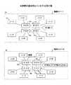
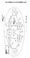
図1は、本発明の基本的なコンセプトを示す図である。ここでは、図1(a)に示すように、複数のノード11が4台のIP−STP12a〜12dにより接続されたネットワーク構成を想定する。なお、ノード11は、上述した信号端局である。 FIG. 1 is a diagram showing the basic concept of the present invention. Here, as shown in FIG. 1A, a network configuration in which a plurality of
上記ネットワークにおいて、複数のノード11およびIP−STP12a〜12dには互いに異なる信号局コードが割り当てられる。すなわち、図1(a)に示す例では、IP−STP12a〜12dに対して合計4個の信号局コードが割り当てられている。 In the network, different signal station codes are assigned to the plurality of
本発明のネットワークシステムでは、図1(b)に示すように、IP−STPに対して割り当てられる信号局コードの数は、IP−STPの数よりも少ない。すなわち、本発明のネットワークシステムでは、複数のIP−STPに対して1つの信号局コードが割り当てられる。例えば、1つの信号局コードがIP−STP12a〜12dに対して割り当てられるようにしてもよい。この場合、ノード11は、IP−STPが1台だけ存在していると認識する。あるいは、IP−STP12a〜12dのなかの2台に対してある1つの信号局コードを割り当てると共に、他の2台に対して別の1つの信号局コードを割り当てるようにしてもよい。この場合、ノード11は、IP−STPが2台だけ存在していると認識する。 In the network system of the present invention, as shown in FIG. 1B, the number of signaling station codes assigned to IP-STP is smaller than the number of IP-STPs. That is, in the network system of the present invention, one signal station code is assigned to a plurality of IP-STPs. For example, one signal station code may be assigned to the IP-
また、このネットワークにおいて制御信号を転送するためのルーチングテーブルは、論理ネットワーク毎に分割して管理される。ここで、図1(b)に示す例では、論理ネットワークAは、複数のノード11及びIP−STP12a〜12dから構成されている。他方、論理ネットワークBは、IP−STP12a〜12dから構成されている。そして、各IP−STPに設けられるルーチングテーブルは、ノード間の信号転送およびノードとIP−STPとの間の信号転送のための情報と、IP−STP間の信号転送のための情報とが分割して管理される。 In addition, a routing table for transferring control signals in this network is divided and managed for each logical network. Here, in the example illustrated in FIG. 1B, the logical network A is configured by a plurality of
このように、本発明のネットワークシステムでは、IP−STPに割り当てるべき信号局コードの数が少なくなるので、信号局コードの不足または枯渇の問題が緩和される。また、IP−STPに割り当てるべき信号局コードの数が少ないので、ノード11においてIP−STPに係わる情報の設定および管理が簡単になる。 As described above, in the network system according to the present invention, the number of signal station codes to be allocated to the IP-STP is reduced, so that the problem of signal station code shortage or exhaustion is alleviated. Further, since the number of signal station codes to be assigned to the IP-STP is small, the setting and management of information related to the IP-STP in the
図2は、下記の実施例で想定するネットワークシステムの構成を示す図である。ここでは、ネットワークシステムは、2台の信号端局(ノード11X、11Y)、4台の信号中継局(IP−STP12a〜12d)、それらの信号局(信号端局および信号中継局を含む)を接続するための10本のリンクから構成されている。なお、これらのリンクは、SCTP(Stream Control Transmission Protocol)では「アソシエイト(Associate)」と呼ばれている。 FIG. 2 is a diagram illustrating a configuration of a network system assumed in the following embodiment. Here, the network system includes two signal terminal stations (
また、このネットワークシステムは、「ネットワーク識別子NI=0」により識別される論理ネットワークA、および「ネットワーク識別子NI=15」により識別される論理ネットワークBが存在する。ここで、論理ネットワークAには、ノード11X、11Y、およびIP−STP12a〜12dが存在し、論理ネットワークBには、IP−STP12a〜12dが存在する。 Further, this network system includes a logical network A identified by “network identifier NI = 0” and a logical network B identified by “network identifier NI = 15”. Here,
図3は、共通線信号方式で使用される制御信号のフォーマットを示す図である。ここでは、MTP3(Message Transfer Part level-3)信号のフォーマットを示す。なお、MTPは、共通線信号方式のメッセージを転送するためのプロトコルである。 FIG. 3 is a diagram showing a format of a control signal used in the common line signal system. Here, the format of an MTP3 (Message Transfer Part level-3) signal is shown. Note that MTP is a protocol for transferring a common line signaling message.
「SIO」は、4ビットのSI領域および4ビットのSSF領域から構成されている。そして、このSSFビットの中の2ビットを用いて「ネットワーク識別子NI」が設定される。ただし、現在、日本国内の通信では、ネットワーク識別子NIとして「0」が固定的に使用されている。 “SIO” is composed of a 4-bit SI area and a 4-bit SSF area. Then, “network identifier NI” is set using 2 bits of the SSF bits. However, at present, “0” is fixedly used as the network identifier NI in communications in Japan.
「DPC」は、着信先信号局の信号局コードを設定するための領域であり、「OPC」は、発信元信号局の信号局コードを設定するための領域である。ここで、「DPC」および「OPC」には、それぞれ16ビットが割り当てられている。また、「CIC」は、回線識別コードであり、「A/Bビット」を含む。ここで、「A/Bビット」は、ネットワークが冗長的に構成されている場合に、通信経路としてA面/B面のいずれの面を使用するのかを指定する。 “DPC” is an area for setting the signal station code of the destination signal station, and “OPC” is an area for setting the signal station code of the source signal station. Here, 16 bits are assigned to “DPC” and “OPC”, respectively. “CIC” is a line identification code and includes “A / B bit”. Here, the “A / B bit” designates which side of the A side / B side is used as a communication path when the network is configured redundantly.
上記制御信号は、図2に示す任意の信号局(ノード11X、11Y、IP−STP12a〜12dを含む)により生成されてネットワークに送出される。そして、各信号局は、受信信号の「ネットワーク識別子NI」および「着信先信号局コードDPS」を参照し、その信号を着信先の信号局へ転送する。 The control signal is generated by an arbitrary signal station (including
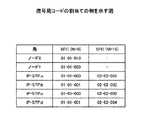
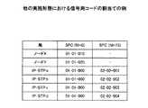
図4は、信号局コードの割当ての例を示す図である。なお、信号局コードは、例えば、ネットワークの管理者により割り当てられる。
実施形態のシステムでは、信号局コードは、ネットワーク識別子毎に割り当てられる。すなわち、「ネットワーク識別子NI=0」により識別される論理ネットワークAにおいては、ノード11Xおよび11Yに対して、それぞれ「NI=01−01−010」および「01−01−020」が割り当てられている。また、IP−STP12a、12cに対して「01−01−000」が割り当てられるとともに、IP−STP12b、12dに対して「01−01−001」が割り当てられている。FIG. 4 is a diagram illustrating an example of signal station code assignment. The signal station code is assigned by a network administrator, for example.
In the system of the embodiment, a signaling station code is assigned for each network identifier. That is, in the logical network A identified by “network identifier NI = 0”, “NI = 01-01-010” and “01-01-020” are assigned to the
このように、この論理ネットワークにおいては、各信号端局(ノード11X、11Y)に対して互いに異なる信号局コードが割り当てられる。ところが、信号中継局(IP−STP12a〜12d)に対しては、その信号中継局の台数よりも少ない数の信号局コードが割り当てられる。具体的には、4台の信号中継局に対して2つの信号局コードが割り当てられている。したがって、この場合、ノード11X、11Yからは、2台の信号中継局しか見えないことになる。 Thus, in this logical network, different signal station codes are assigned to the signal terminal stations (
また、別の見かたをすれば、ノード11X、11Y間には、「01−01−000」により識別されるIP−STPを経由するルート(ノード11X、IP−STP12a、IP−STP12c、ノード11Y)、及び「01−01−001」により識別されるIP−STPを経由するルート(ノード11X、IP−STP12b、IP−STP12d、ノード11Y)が存在することになる。すなわち、冗長的な構成が実現される。なお、前者のルートを「A面」、後者のルートを「B面」と呼ぶことがある。 In another way, between the
一方、「ネットワーク識別子NI=15」により識別される論理ネットワークBにおいては、IP−STP12a、12b、12c、12dに対して、それぞれ「02−02−001」「02−02−002」「02−02−003」「02−02−004」が割り当てられている。すなわち、この論理ネットワークにおいては、各信号中継局に対して互いに異なる信号局コードが割り当てられる。 On the other hand, in the logical network B identified by “network identifier NI = 15”, “02-02-001”, “02-02-002”, “02-” are assigned to the IP-
なお、ネットワーク識別子NIは、上述したMTP3信号が転送される既存のネットワークシステムでは、図3に示すSSF領域の中の2ビットを用いて表されるが、実施形態のシステムでは、4ビットのSSF領域全体を用いて表される。 The network identifier NI is represented by using 2 bits in the SSF area shown in FIG. 3 in the existing network system to which the MTP3 signal described above is transferred, but in the system of the embodiment, the network identifier NI is 4 bits. Represented using the entire region.
各信号局は、それぞれ、後述する自局コードテーブル、アソシエイトテーブル、ルーチングテーブルを備える。そして、これらのテーブルの内容は、上述した信号局コードの割当てに基づいて設定される。 Each signal station includes a local code table, an associate table, and a routing table, which will be described later. The contents of these tables are set based on the above-described assignment of signal station codes.
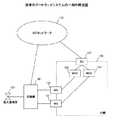
図5は、IP−STPの構成図である。NICカード21は、回線を終端するインタフェース機能を提供する。OS/IPルート管理部22は、下位レイヤの信号処理を実行する。SCTP制御部23は、SCTP(Stream Control Transmission Protocol)に係わる信号処理を実行する。ルーチングデータ管理部24は、制御信号の転送に係わる情報(ルーチングテーブルを含む)を格納および管理する。転送制御部25は、メッセージの転送に係わる制御(MTP3(Message Transfer Part level-3)、M3UA(Mtp3-User Adaptation layer)、M2UA、M2PA、MTP3等)を実行する。O&M部26は、システムの管理者からの指示を受け付け、IP−STPに必要な情報を設定する。 FIG. 5 is a configuration diagram of IP-STP. The
なお、IP−STPは、例えば、コンピュータにNICカード21を装着すると共に、OS/IPルート管理部22〜O&M部26の機能を記述したプログラムを実装することにより実現される。 Note that IP-STP is realized, for example, by mounting the
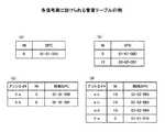
図6は、各信号局に設けられる管理テーブルの例である。ここでは、図2に示すシステムを前提とし、信号端局に設けられる管理テーブルの一例としてノード11Xに設けられる管理テーブルを示し、また、信号中継局に設けられる管理テーブルの一例としてIP−STP12aに設けられる管理テーブルを示す。 FIG. 6 is an example of a management table provided in each signal station. Here, on the premise of the system shown in FIG. 2, a management table provided in the
図6(a)は、ノード11Xに設けられる自局コードテーブルの例であり、図6(b)は、IP−STP12aに設けられる自局コードテーブルの例である。このように、自局コードテーブルは、各信号局が属する論理ネットワークを識別するネットワーク識別子NIおよび信号局コードSPCの組合せが登録される。なお、各IP−STP(ここでは、IP−STP12a)は、論理ネットワークA、Bの双方に属するので、図6(b)に示すように、論理ネットワークAにおける信号局コードおよび論理ネットワークBにおける信号局コードの双方が登録されている。 6A is an example of the local station code table provided in the
図6(c)および図6(d)は、それぞれ、ノード11XおよびIP−STP12aに設けられるアソシエイトテーブルの例である。アソシエイトテーブルには、自局に接続されているリンク(すなわち、アソシエイト)毎に、そのリンクが属する論理ネットワークのネットワーク識別子NI、およびそのリンクの接続先の信号局の信号局コード(対向SPC)が登録される。例えば、図6(c)において、「アソシエイトX−a」は、「NI=0」により識別される論理ネットワークを介してノード11XとIP−STP12aとを接続するリンクを表し、「アソシエイトX−b」は、「NI=0」により識別される論理ネットワークを介してノード11XとIP−STP12bとを接続するリンクを表している。また、図6(d)において、「アソシエイトa−c」は、「NI=15」により識別される論理ネットワークを介してIP−STP12aとIP−STP12cとを接続するリンクを表し、「アソシエイトa−b」は、「NI=15」により識別される論理ネットワークを介してIP−STP12aとIP−STP12bとを接続するリンクを表し、「アソシエイトa−d」は、「NI=15」により識別される論理ネットワークを介してIP−STP12aとIP−STP12dとを接続するリンクを表し、さらに、「アソシエイトX−a」は、「NI=0」により識別される論理ネットワークを介してノード11XとIP−STP12aとを接続するリンクを表している。 FIG. 6C and FIG. 6D are examples of associate tables provided in the
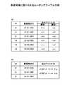
図7は、各信号局に設けられるルーチングテーブルの例である。ここでは、図2に示すシステムを前提とし、信号端局に設けられるルーチングテーブルの一例としてノード11Xに設けられるルーチングテーブルを図7(a)に示し、また、信号中継局に設けられるルーチングテーブルの一例としてIP−STP12aに設けられるルーチングテーブルを図7(b)に示す。なお、これらのルーチングテーブルは、制御信号をその着信先へ転送するために使用される。 FIG. 7 is an example of a routing table provided in each signal station. Here, assuming the system shown in FIG. 2, a routing table provided in the
図7(a)において、第1〜第3レコードには、「ネットワーク識別子NI=0」により識別される論理ネットワークAにおける各着信先信号局コードに対する出力アソシエイトが登録されている。ここで、第3レコードに登録されている着信先は、論理ネットワークAにおいて「信号局コードSPC=01−01−001」により識別される信号局であり、IP−STP12bおよびIP−STP12dを意味する。また、第4〜第6レコードには、「ネットワーク識別子NI=15」により識別される論理ネットワークBにおける各着信先信号局コードに対する出力アソシエイトが登録されている。なお、1つの着信先に対して複数の出力アソシエイトが存在する場合には、各出力アソシエイトに優先順位が付される。 In FIG. 7A, output associates for each destination signal station code in the logical network A identified by “network identifier NI = 0” are registered in the first to third records. Here, the destinations registered in the third record are signal stations identified by “signal station code SPC = 0-01-01-001” in the logical network A, which means IP-
信号端局においては、図7(b)に示すように、図3に示したA/Bビットの値により出力アソシエイトが決定される。この例では、ノード11Xにおいて、「A/Bビット=0」のときにアソシエイトX−aが選択され、「A/Bビット=1」のときにアソシエイトX−bが選択される旨を定義した情報が格納されている。そして、制御信号を送信しようとする信号端局は、A/Bビットを利用して、冗長的に構成されているIP−STP網のA面またはB面を指定できる。すなわち、制御信号を送信しようとする信号端局においてA/Bビットを適切に設定することにより、IP−STP網のロードバランス(負荷分散)を実現できる。 In the signal terminal station, as shown in FIG. 7B, the output associate is determined by the value of the A / B bit shown in FIG. In this example, the
次に、上述のネットワークシステムにおける信号転送の例を説明する。 Next, an example of signal transfer in the above network system will be described.
実施例1では、ノード11Xからノード11Yへ制御信号を転送する場合の手順を説明する。この場合、ノード11Xにより作成される制御信号には、図3に示すフォーマットにおいて以下の情報が設定される。すなわち、SSF領域には、「NI=0」が設定される。このとき、既存の方式と同様にSSF領域の中の予め規定されている所定の2ビットを用いて「NI=0」が設定されてもよいし、4ビットのSSF領域全体を利用して「NI=0」が設定されるようにしてもよい。また、DPC領域には、ノード11Yを表す信号局コード「01−01−020」が設定され、OPC領域には、ノード11Xを表す信号局コード「01−01−010」が設定される。さらに、「A/Bビット」には、「0」が設定されるものとする。なお、信号情報領域には、ノード11Yに通知すべき情報またはコマンド等が格納されている。 In the first embodiment, a procedure for transferring a control signal from the
そして、上述のようにして作成された制御信号は、以下の手順によりノード11Xからノード11Yへ転送される。なお、この手順は、図8を参照しながら説明する。
1.ノード11Xは、まず、制御信号に設定されている「A/Bビット=0」に従ってアソシエイトX−aを選択する。そして、その選択されたアソシエイトX−aを介してその制御信号を送出する。この結果、この制御信号は、IP−STP12aにより受信される。The control signal created as described above is transferred from the
1. The
2.IP−STP12aは、受信した制御信号からネットワーク識別子NIおよび着信先信号局コードDPCを抽出し、それらの値を検索キーとしてルーチングテーブルを参照する。ここで、IP−STP12aに設けられているルーチングテーブルは、図7(a)に示した通りである。したがって、「NI=0」および「SPC=01−01−020」に基づいて出力アソシエイトとして「a−c」が得られる。このとき、出力アソシエイトの選択は、ルーチングテーブルに登録されている優先順位に従う。そして、IP−STP12aは、ノード11Xから受信した制御信号をアソシエイトa−cに出力する。この結果、この制御信号は、IP−STP12cに転送される。 2. The IP-
3.IP−STP12cの動作は、基本的に、上述したIP−STP12aの動作と同じである。すなわち、IP−STP12cは、ルーチングテーブルを利用して出力アソシエイトを決定し、IP−STP12aから受信した制御信号をその決定したアソシエイトに出力する。この結果、この制御信号は、ノード11Yに転送される。 3. The operation of the IP-
4.ノード11Yは、受信した制御信号の着信先信号局コードDPCが自己の信号局コードと一致していることを検出すると、その制御信号に格納されている通知またはコマンドに対応する動作を実行する。 4). When the node 11Y detects that the destination signal station code DPC of the received control signal matches its own signal station code, the node 11Y performs an operation corresponding to the notification or command stored in the control signal.
このように、信号端局間での信号転送においては、ネットワーク識別子として「NI=0」を設定するとともに、そのネットワーク識別子により識別される論理ネットワーク上で割り当てられている信号局コードを着信先として設定することにより、所望の信号端局へ制御信号を送ることができる。このとき、各IP−STPは、それぞれ、ルーチングテーブル内でそのネットワーク識別子と対応付けて管理されている情報を参照して制御信号を着信先へ転送する。 Thus, in signal transfer between signal terminal stations, “NI = 0” is set as the network identifier, and the signal station code assigned on the logical network identified by the network identifier is used as the destination. By setting, a control signal can be sent to a desired signal terminal station. At this time, each IP-STP refers to the information managed in association with the network identifier in the routing table and transfers the control signal to the destination.
実施例2では、ノード11XとIP−STP12bとを接続するアソシエイトX−bに障害が発生した際の手順を説明する。ここでは、たとえば、ノード11XからIP−STP12bへ制御信号を送信している途中でアソシエイトX−bに障害が発生したものとする。すなわち、上記障害が発生する前は、制御信号に「NI=0」および「SPC=01−01−010」が設定されており、ノード11XからIP−STP12bへアソシエイトX−bを介してその制御信号が送られていたものとする。また、ノード11Xは、何らかの方法(例えば、IP−STP12bからの通知)により上記障害を検出したものとする。以下、図9を参照しながら、実施例2の手順を説明する。 In the second embodiment, a procedure when a failure occurs in the associate X-b connecting the
1.ノード11Xは、後続の制御信号または再送すべき制御信号に、上記障害発生前と同じネットワーク識別子NIおよび着信先信号局コードSPCを設定する。すなわち、この制御信号には「NI=0」および「SPC=01−01−010」が設定される。ただし、アソシエイトX−bに障害が発生しているので、この制御信号のA/Bビットには、IP−STP12a、12cから構成されるA面を指示する「1」が設定される。 1. The
2.ノード11Xは、A/Bビットに従って上記制御信号を送出する。すなわち、ノード11Xは、上記制御信号をアソシエイトX−aへ出力する。この結果、上記制御信号はIP−STP12aにより受信される。 2. The
3.IP−STP12aは、受信した制御信号からネットワーク識別子NIおよび着信先信号局コードDPCを抽出し、それらの値を検索キーとしてルーチングテーブルを参照する。ここで、IP−STP12aに設けられているルーチングテーブルは、図7(a)に示した通りである。したがって、「NI=0」および「SPC=01−01−001」に基づいて出力アソシエイトとして「a−b」が得られる。そして、IP−STP12aは、ノード11Xから受信した制御信号をアソシエイトa−bに出力する。この結果、この制御信号は、IP−STP12bに転送される。 3. The IP-
4.IP−STP12bは、受信した制御信号に格納されている通知またはコマンドに対応する動作を実行する。
このように、信号端局と信号中継局との間のリンクに障害が発生した場合であっても、制御信号は、障害発生前と同じネットワーク識別子および着信先信号局コードにより、他のルートを介して目的の着信先に転送される。4). The IP-
In this way, even when a failure occurs in the link between the signal terminal station and the signal relay station, the control signal is routed to another route by the same network identifier and destination signal station code as before the failure occurrence. To the desired destination.
実施例3では、ノード11XとIP−STP12aとを接続するアソシエイトX−aに障害が発生した際の手順を説明する。具体的には、IP−STP12aがアソシエイトX−aの障害を検出し、隣接する全てのIP−STPへその旨を通知する手順を説明する。以下、図10を参照しながら、実施例3の手順を説明する。 In the third embodiment, a procedure when a failure occurs in the associate X-a that connects the
1.IP−STP12aは、上記障害を検出すると、図6(d)に示したアソシエイトテーブルを参照し、IP−STP12aに隣接するすべての信号局を認識する。そして、これらの信号局をそれぞれ着信先とする制御信号を作成する。ただし、アソシエイトX−aに障害が発生しているので、ノード11X宛ての制御信号は作成しない。すなわち、IP−STP12b、12c、12d宛ての制御信号を作成する。このとき、これらの制御信号は信号中継局間で送受信されるので、これらの制御信号には、それぞれ「ネットワーク識別子NI=15」が設定される。また、着信先信号局コードとしては、「ネットワーク識別子NI=15」と対応付けられている値(02−02−002、02−02−003、02−02−004)が設定される。なお、この制御信号は、アソシエイトX−aを介した信号転送を禁止する旨を表示した転送禁止信号である。 1. When detecting the failure, the IP-
2.上述のようにして作成した制御信号を、各隣接信号局へ送出する。このとき、「NI=15、SPC=02−02−002」が設定された制御信号は、アソシエイトa−bを介してIP−STP12bへ送られ、「NI=15、SPC=02−02−003」が設定された制御信号は、アソシエイトa−cを介してIP−STP12cへ送られ、「NI=15、SPC=02−02−004」が設定された制御信号は、アソシエイトa−dを介してIP−STP12dへ送られる。 2. The control signal created as described above is sent to each adjacent signal station. At this time, the control signal in which “NI = 15, SPC = 0-02-022” is set is sent to the IP-
3.IP−STP12b〜12dは、それぞれ、受信した制御信号(転送禁止信号)に対応する動作を実行する。具体的には、例えば、制御信号が転送ルートからアソシエイトX−aが外れるように、各IP−STPのルーチングテーブルが更新される。 3. Each of the IP-
このように、IP−STPに接続するリンクに障害が発生したときは、それを検出したIP−STPから他のIP−STPへ転送禁止信号が送られる。そして、転送禁止信号を受け取ったIP−STPは、その転送禁止信号に従い、障害の発生したリンクを迂回するルートを実現するための情報を設定するためにルーチングテーブルを更新する。したがって、以降、制御信号は、障害が発生したリンクを迂回して所望の信号局へ転送される。 As described above, when a failure occurs in the link connected to the IP-STP, a transfer prohibition signal is transmitted from the IP-STP that has detected the failure to another IP-STP. Then, the IP-STP that has received the transfer prohibition signal updates the routing table in accordance with the transfer prohibition signal in order to set information for realizing a route that bypasses the failed link. Therefore, thereafter, the control signal is transferred to a desired signal station bypassing the link where the failure has occurred.
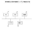
図11は、信号端局および信号中継局のハードウェア構成を示す図である。実施形態の信号端局および信号中継局は、例えば、図11に示すようなコンピュータにより実現することができ、CPU51、メモリ52、記憶部53、ユーザI/F部54、通信I/F部55を備える。そして、信号端局または信号中継局の動作を記述したプログラムが記憶部53(または、メモリ52)に格納されており、そのプログラムを実行することにより上述の動作が実現される。また、図6〜図7に示したテーブルは、メモリ52(または、記憶部53)に設けられる。 FIG. 11 is a diagram illustrating a hardware configuration of the signal terminal station and the signal relay station. The signal terminal station and the signal relay station of the embodiment can be realized by, for example, a computer as shown in FIG. 11, and includes a
また、ネットワーク識別子NIおよび信号局コードSPCは、例えば、ネットワーク管理者により決定され、ユーザI/F部54または通信I/F部55を介して各信号局に設定される。ここで、「ネットワーク識別子の設定」および「信号局コード(ノード識別子)の割当て」は、決定した値を各信号局が備えるテーブルに登録する動作を含むものとする。 The network identifier NI and the signal station code SPC are determined by, for example, a network administrator, and set in each signal station via the user I /
なお、上述の実施例では、IP−STP網に対して2つの信号局コードを割り当てることによりIP−STP網の二重化を図っているが、本発明はこの構成に限定されるものではない。すなわち、図12に示すように、IP−STP網全体に対して信号局コードを1つだけ割り当てるようにしてもよい。すなわち、IP−STP網を構成するすべてのIP−STPに対して同じ信号局コードを割り当てるようにしてもよい。この場合、信号端局は、IP−STPが1台だけ存在すると認識する。あるいは、IP−STP網に対して3以上の信号局コードを割り当てるようにしてもよい。ただし、この場合であっても、IP−STP網全体に対して割り当てられる信号局コードの数は、そのIP−STP網を構成するIP−STPの台数よりも少ないものとする。 In the above-described embodiment, the IP-STP network is duplexed by assigning two signal station codes to the IP-STP network, but the present invention is not limited to this configuration. That is, as shown in FIG. 12, only one signal station code may be assigned to the entire IP-STP network. In other words, the same signal station code may be assigned to all IP-STPs constituting the IP-STP network. In this case, the signal terminal station recognizes that only one IP-STP exists. Alternatively, three or more signal station codes may be assigned to the IP-STP network. However, even in this case, the number of signaling station codes assigned to the entire IP-STP network is smaller than the number of IP-STPs constituting the IP-STP network.
また、上述の実施例では、共通線信号方式の一形態として「No.7」を採り上げて説明をしたが、本発明はこれに限定されるものではなく、他の共通線信号方式の信号を転送するためのネットワークシステムにも適用可能である。 In the above-described embodiment, “No. 7” is taken as an example of the common line signal system, but the present invention is not limited to this, and signals of other common line signal systems are used. It is also applicable to a network system for transferring.
さらに、上述の実施例では、既存の回線交換網を介してIPネットワークサービスを提供するシステムを想定しているが、本発明はこれに限定されるものではない。すなわち、本発明の信号端局は、メディアゲートウェイ、シグナリングゲートウェイ、メディアゲートウェイコントローラに限定されるものではない。また、本発明の信号中継局は、IP網に設けられるIP−STPに限定されるものではない。 Furthermore, in the above-described embodiment, a system that provides an IP network service via an existing circuit switching network is assumed, but the present invention is not limited to this. That is, the signal terminal station of the present invention is not limited to the media gateway, the signaling gateway, and the media gateway controller. The signal relay station of the present invention is not limited to the IP-STP provided in the IP network.
(付記1)複数の信号端局および複数の信号中継局を含み、ネットワーク識別子およびノード識別子に基づいて共通線信号方式の制御信号を転送するネットワークシステムであって、
上記複数の信号端局および上記複数の信号中継局を含む論理ネットワークに対して第1のネットワーク識別子を設定すると共に、上記複数の信号中継局のみを含む論理ネットワークに対して第2のネットワーク識別子を設定する設定手段と、
上記第1のネットワーク識別子に対応づけて上記複数の信号端局および上記複数の信号中継局に第1のグループに属するノード識別子を割り当てると共に、上記第2のネットワーク識別子に対応づけて上記複数の信号中継局に第2のグループに属するノード識別子を割り当てる割当て手段、
を備え、
上記複数の信号中継局に割り当てられる上記第1のグループに属するノード識別子の数は、それら複数の信号中継局の数よりも少ない
ことを特徴とするネットワークシステム。
(付記2)付記1に記載のネットワークシステムであって、
上記第1のネットワーク識別子は、上記信号端局間の信号転送において使用され、上記第2のネットワーク識別子は、上記信号中継局間の信号転送において使用される。
(付記3)付記2に記載のネットワークシステムであって、
上記第1のネットワーク識別子は、上記信号端局と上記信号中継局との間の信号転送にも使用さる。(Appendix 1) A network system including a plurality of signal terminal stations and a plurality of signal relay stations, and transferring a control signal of a common line signal system based on a network identifier and a node identifier,
A first network identifier is set for a logical network including the plurality of signal terminal stations and the plurality of signal relay stations, and a second network identifier is set for a logical network including only the plurality of signal relay stations. Setting means for setting;
A node identifier belonging to a first group is assigned to the plurality of signal terminal stations and the plurality of signal relay stations in association with the first network identifier, and the plurality of signals in association with the second network identifier. An assigning means for assigning a node identifier belonging to the second group to the relay station;
With
The network system characterized in that the number of node identifiers belonging to the first group assigned to the plurality of signal relay stations is smaller than the number of the plurality of signal relay stations.
(Appendix 2) The network system according to
The first network identifier is used in signal transfer between the signal terminal stations, and the second network identifier is used in signal transfer between the signal relay stations.
(Supplementary note 3) The network system according to
The first network identifier is also used for signal transfer between the signal terminal station and the signal relay station.
(付記4)付記1に記載のネットワークシステムであって、
上記信号端局間の信号転送には、上記第1のネットワーク識別子および上記第1のグループに属するノード識別子が使用され、上記信号中継局間の信号転送には、上記第2のネットワーク識別子および上記第2のグループに属するノード識別子が使用される。(Supplementary note 4) The network system according to
The signal transfer between the signal terminal stations uses the first network identifier and the node identifier belonging to the first group, and the signal transfer between the signal relay stations uses the second network identifier and the node identifiers. Node identifiers belonging to the second group are used.
(付記5)付記1に記載のネットワークシステムであって、
上記設定手段は、上記複数の信号中継局に対して上記第1のグループに属する同一のノード識別子を割り当てる。(Supplementary note 5) The network system according to
The setting means assigns the same node identifier belonging to the first group to the plurality of signal relay stations.
(付記6)付記1に記載のネットワークシステムであって、
上記設定手段は、上記複数の信号中継局のなかの一部の信号中継局に対して上記第1のグループに属する第1のノード識別子を割り当てると共に、上記複数の信号中継局のなかの他の残りの信号中継局に対して上記第1のグループに属する第2のノード識別子を割り当てる。
(付記7)付記1に記載のネットワークシステムであって、
上記設定手段は、上記第1のグループに属するノード識別子を上記複数の信号中継局に対して重複して割り当てる。(Supplementary note 6) The network system according to
The setting means allocates a first node identifier belonging to the first group to a part of the signal relay stations of the plurality of signal relay stations, and sets the other ones of the plurality of signal relay stations. The second node identifier belonging to the first group is assigned to the remaining signal relay stations.
(Supplementary note 7) The network system according to
The setting means redundantly assigns node identifiers belonging to the first group to the plurality of signal relay stations.
(付記8)付記1に記載のネットワークシステムであって、
上記複数の信号端局は、それぞれ、隣接する信号中継局との間のリンクを識別する情報として上記第1のネットワーク識別子と上記第1のグループに属するノード識別子との組合せを格納するリンク情報格納手段を有する。(Supplementary note 8) The network system according to
Each of the plurality of signal terminal stations stores a link information storing a combination of the first network identifier and the node identifier belonging to the first group as information for identifying a link with an adjacent signal relay station. Have means.
(付記9)付記1に記載のネットワークシステムであって、
上記複数の信号中継局は、それぞれ、隣接する信号端局との間のリンクを識別する情報として上記第1のネットワーク識別子と上記第1のグループに属するノード識別子との組合せを格納すると共に、隣接する信号中継局との間のリンクを識別する情報として上記第2のネットワーク識別子と上記第2のグループに属するノード識別子との組合せを格納するリンク情報格納手段を有する。(Supplementary note 9) The network system according to
Each of the plurality of signal relay stations stores a combination of the first network identifier and the node identifier belonging to the first group as information for identifying a link with an adjacent signal terminal station. Link information storage means for storing a combination of the second network identifier and the node identifier belonging to the second group as information for identifying a link with the signal relay station.
(付記10)付記1に記載のネットワークシステムであって、
上記複数の信号中継局は、それぞれ、上記第1のグループに属するノード識別子または上記第2のグループに属するノード識別子により表された宛先情報ごとに上記制御信号を出力すべきリンクを表すリンク情報が登録されたルーチングテーブルを備える。
(付記11)付記10に記載のネットワークシステムであって、
上記リンク情報は、上記制御信号を出力すべき複数のリンクの優先順位を表す情報を含む。(Supplementary note 10) The network system according to
Each of the plurality of signal relay stations has link information representing a link to which the control signal should be output for each destination information represented by a node identifier belonging to the first group or a node identifier belonging to the second group. A registered routing table is provided.
(Supplementary note 11) The network system according to supplementary note 10,
The link information includes information indicating the priority order of a plurality of links that should output the control signal.
(付記12)付記10に記載のネットワークシステムであって、
上記複数の信号中継局は、それぞれ、
障害の発生したリンクを表す障害情報を他の信号中継局に通知する手段と、
通知された障害情報に従ってルーチングテーブルを更新する手段、
を有する。(Supplementary note 12) The network system according to supplementary note 10,
Each of the plurality of signal relay stations is
Means for notifying other signaling relay stations of failure information indicating a failed link;
Means for updating the routing table in accordance with the notified fault information;
Have
(付記13)複数の信号端局および複数の信号中継局を含み、ネットワーク識別子およびノード識別子に基づいて共通線信号方式の制御信号を転送するネットワークシステムであって、
信号端局間の信号転送のために第1のネットワーク識別子を設定すると共に、信号中継局間の信号転送のために第2のネットワーク識別子を設定する設定手段と、
上記第1のネットワーク識別子に対応づけて上記複数の信号端局および上記複数の信号中継局に第1のグループに属するノード識別子を割り当てると共に、上記第2のネットワーク識別子に対応づけて上記複数の信号中継局に第2のグループに属するノード識別子を割り当てる割当て手段、
を備え、
上記複数の信号中継局に割り当てられる上記第1のグループに属するノード識別子の数は、それら複数の信号中継局の数よりも少ない
ことを特徴とするネットワークシステム。
(付記14)複数の信号端局および複数の信号中継局を含みネットワーク識別子およびノード識別子に基づいて共通線信号方式の制御信号を転送するネットワークシステムを構築する方法であって、
上記複数の信号端局および上記複数の信号中継局を含む論理ネットワークに対して第1のネットワーク識別子を設定し、
上記複数の信号中継局のみを含む論理ネットワークに対して第2のネットワーク識別子を設定し、
上記第1のネットワーク識別子に対応づけて上記複数の信号端局および上記複数の信号中継局に第1のグループに属するノード識別子を割り当て、
上記第2のネットワーク識別子に対応づけて上記複数の信号中継局に第2のグループに属するノード識別子を割り当て、
上記複数の信号中継局に割り当てられる上記第1のグループに属するノード識別子の数は、それら複数の信号中継局の数よりも少ない
ことを特徴とするネットワークシステム構築方法。(Supplementary note 13) A network system including a plurality of signal terminal stations and a plurality of signal relay stations, and transferring a control signal of a common line signal system based on a network identifier and a node identifier,
Setting means for setting a first network identifier for signal transfer between signal terminal stations and setting a second network identifier for signal transfer between signal relay stations;
A node identifier belonging to a first group is assigned to the plurality of signal terminal stations and the plurality of signal relay stations in association with the first network identifier, and the plurality of signals in association with the second network identifier. An assigning means for assigning a node identifier belonging to the second group to the relay station;
With
The network system characterized in that the number of node identifiers belonging to the first group assigned to the plurality of signal relay stations is smaller than the number of the plurality of signal relay stations.
(Supplementary note 14) A method of constructing a network system including a plurality of signal terminal stations and a plurality of signal relay stations and transferring a control signal of a common line signal system based on a network identifier and a node identifier,
Setting a first network identifier for a logical network including the plurality of signal terminal stations and the plurality of signal relay stations;
Setting a second network identifier for a logical network including only the plurality of signal relay stations,
A node identifier belonging to a first group is assigned to the plurality of signal terminal stations and the plurality of signal relay stations in association with the first network identifier,
A node identifier belonging to a second group is assigned to the plurality of signal relay stations in association with the second network identifier,
The network system construction method characterized in that the number of node identifiers belonging to the first group allocated to the plurality of signal relay stations is smaller than the number of the plurality of signal relay stations.
11(11X、11Y) ノード(信号端局)
12(12a〜12d) IP−STP(信号中継局)
21 NICカード
22 OS/IPルート管理部
23 SCTP制御部
24 ルーチングデータ管理部
25 転送制御部
26 O&M部
101 加入者端末
102 交換機
110 SS7ネットワーク
120 IP網
121 メディアゲートウェイ(MG)
122 シグナリングゲートウェイ(SG)
123 メディアゲートウェイコントローラ(MGC)
11 (11X, 11Y) Node (Signal Terminal)
12 (12a to 12d) IP-STP (Signal Relay Station)
21 NIC card 22 OS / IP
122 Signaling Gateway (SG)
123 Media Gateway Controller (MGC)
Claims (5)
Translated fromJapanese上記複数の信号端局および上記複数の信号中継局を含む論理ネットワークに対して第1のネットワーク識別子を設定すると共に、上記複数の信号中継局のみを含む論理ネットワークに対して第2のネットワーク識別子を設定する設定手段と、
上記第1のネットワーク識別子に対応づけて上記複数の信号端局および上記複数の信号中継局に第1のグループに属するノード識別子を割り当てると共に、上記第2のネットワーク識別子に対応づけて上記複数の信号中継局に第2のグループに属するノード識別子を割り当てる割当て手段、
を備え、
上記複数の信号中継局に割り当てられる上記第1のグループに属するノード識別子の数は、それら複数の信号中継局の数よりも少ない
ことを特徴とするネットワークシステム。A network system including a plurality of signal terminal stations and a plurality of signal relay stations, and transferring a control signal of a common line signaling system based on a network identifier and a node identifier,
A first network identifier is set for a logical network including the plurality of signal terminal stations and the plurality of signal relay stations, and a second network identifier is set for a logical network including only the plurality of signal relay stations. Setting means for setting;
A node identifier belonging to a first group is assigned to the plurality of signal terminal stations and the plurality of signal relay stations in association with the first network identifier, and the plurality of signals in association with the second network identifier. An assigning means for assigning a node identifier belonging to the second group to the relay station;
With
The network system characterized in that the number of node identifiers belonging to the first group assigned to the plurality of signal relay stations is smaller than the number of the plurality of signal relay stations.
上記第1のネットワーク識別子は、上記信号端局間または上記信号端局と上記信号中継局との間の信号転送において使用され、上記第2のネットワーク識別子は、上記信号中継局間の信号転送において使用される。The network system according to claim 1,
The first network identifier is used in signal transfer between the signal terminal stations or between the signal terminal station and the signal relay station, and the second network identifier is used in signal transfer between the signal relay stations. used.
上記設定手段は、上記複数の信号中継局のなかの一部の信号中継局に対して上記第1のグループに属する第1のノード識別子を割り当てると共に、上記複数の信号中継局のなかの他の残りの信号中継局に対して上記第1のグループに属する第2のノード識別子を割り当てる。The network system according to claim 1,
The setting means allocates a first node identifier belonging to the first group to a part of the signal relay stations of the plurality of signal relay stations, and sets the other ones of the plurality of signal relay stations. The second node identifier belonging to the first group is assigned to the remaining signal relay stations.
上記複数の信号中継局は、それぞれ、上記第1のグループに属するノード識別子または上記第2のグループに属するノード識別子により表された宛先情報ごとに上記制御信号を出力すべきリンクを表すリンク情報が登録されたルーチングテーブルを備える。The network system according to claim 1,
Each of the plurality of signal relay stations has link information representing a link to which the control signal should be output for each destination information represented by a node identifier belonging to the first group or a node identifier belonging to the second group. A registered routing table is provided.
信号端局間の信号転送のために第1のネットワーク識別子を設定すると共に、信号中継局間の信号転送のために第2のネットワーク識別子を設定する設定手段と、
上記第1のネットワーク識別子に対応づけて上記複数の信号端局および上記複数の信号中継局に第1のグループに属するノード識別子を割り当てると共に、上記第2のネットワーク識別子に対応づけて上記複数の信号中継局に第2のグループに属するノード識別子を割り当てる割当て手段、
を備え、
上記複数の信号中継局に割り当てられる上記第1のグループに属するノード識別子の数は、それら複数の信号中継局の数よりも少ない
ことを特徴とするネットワークシステム。
A network system including a plurality of signal terminal stations and a plurality of signal relay stations, and transferring a control signal of a common line signaling system based on a network identifier and a node identifier,
Setting means for setting a first network identifier for signal transfer between signal terminal stations and setting a second network identifier for signal transfer between signal relay stations;
A node identifier belonging to a first group is assigned to the plurality of signal terminal stations and the plurality of signal relay stations in association with the first network identifier, and the plurality of signals in association with the second network identifier. An assigning means for assigning a node identifier belonging to the second group to the relay station;
With
The network system characterized in that the number of node identifiers belonging to the first group assigned to the plurality of signal relay stations is smaller than the number of the plurality of signal relay stations.
Priority Applications (2)
| Application Number | Priority Date | Filing Date | Title |
|---|---|---|---|
| JP2003422443AJP2005184467A (en) | 2003-12-19 | 2003-12-19 | Network system using common line signaling |
| US10/858,966US20050135337A1 (en) | 2003-12-19 | 2004-06-02 | Network system using common channel signalling |
Applications Claiming Priority (1)
| Application Number | Priority Date | Filing Date | Title |
|---|---|---|---|
| JP2003422443AJP2005184467A (en) | 2003-12-19 | 2003-12-19 | Network system using common line signaling |
Publications (1)
| Publication Number | Publication Date |
|---|---|
| JP2005184467Atrue JP2005184467A (en) | 2005-07-07 |
Family
ID=34675322
Family Applications (1)
| Application Number | Title | Priority Date | Filing Date |
|---|---|---|---|
| JP2003422443APendingJP2005184467A (en) | 2003-12-19 | 2003-12-19 | Network system using common line signaling |
Country Status (2)
| Country | Link |
|---|---|
| US (1) | US20050135337A1 (en) |
| JP (1) | JP2005184467A (en) |
Cited By (2)
| Publication number | Priority date | Publication date | Assignee | Title |
|---|---|---|---|---|
| JP2009530919A (en)* | 2006-03-16 | 2009-08-27 | ソーナス ネットワークス, インコーポレイテッド | Using a single point code to represent multiple switching devices |
| JP2010062777A (en)* | 2008-09-03 | 2010-03-18 | Nec Corp | Sctp association aggregator, communication system including the same and routing method |
Families Citing this family (5)
| Publication number | Priority date | Publication date | Assignee | Title |
|---|---|---|---|---|
| JP4208710B2 (en)* | 2003-12-24 | 2009-01-14 | 富士通株式会社 | Frame transmission equipment |
| US7356628B2 (en)* | 2005-05-13 | 2008-04-08 | Freescale Semiconductor, Inc. | Packet switch with multiple addressable components |
| US8400947B2 (en)* | 2006-07-20 | 2013-03-19 | Tekelec, Inc. | Methods, systems, and computer program products for specifying a particular ENUM service type in a communications network that utilizes a plurality of different ENUM service types |
| CN101383840B (en)* | 2007-09-05 | 2011-12-21 | 华为技术有限公司 | Network, device and message transmitting method based on M3UA protocol networking |
| JP2010226180A (en)* | 2009-03-19 | 2010-10-07 | Fujitsu Ltd | Communication device |
Family Cites Families (6)
| Publication number | Priority date | Publication date | Assignee | Title |
|---|---|---|---|---|
| US6061432A (en)* | 1997-12-23 | 2000-05-09 | Bell Atlantic Network Services, Inc. | Voice mail system for obtaining routing information from signaling nodes |
| AU2024300A (en)* | 1998-12-01 | 2000-06-19 | Thor Simon | Improved signaling system for telecommunications |
| US6717940B1 (en)* | 1999-12-22 | 2004-04-06 | Lucent Technologies Inc. | Message transfer part level three alias point codes |
| US6515985B2 (en)* | 2000-02-08 | 2003-02-04 | Airslide Systems Ltd. | Convergence of telephone signaling, voice and data over a packet-switched network |
| US7197036B2 (en)* | 2001-08-16 | 2007-03-27 | Tekelec Us | Methods and systems for routing messages between a mated pair of routing nodes with a distributed processing architecture and one or more redundantly connected remote applications |
| US6792100B2 (en)* | 2002-03-08 | 2004-09-14 | Siemens Information And Communication Networks, Inc. | Method and apparatus for sharing point codes in a network |
- 2003
- 2003-12-19JPJP2003422443Apatent/JP2005184467A/enactivePending
- 2004
- 2004-06-02USUS10/858,966patent/US20050135337A1/ennot_activeAbandoned
Cited By (2)
| Publication number | Priority date | Publication date | Assignee | Title |
|---|---|---|---|---|
| JP2009530919A (en)* | 2006-03-16 | 2009-08-27 | ソーナス ネットワークス, インコーポレイテッド | Using a single point code to represent multiple switching devices |
| JP2010062777A (en)* | 2008-09-03 | 2010-03-18 | Nec Corp | Sctp association aggregator, communication system including the same and routing method |
Also Published As
| Publication number | Publication date |
|---|---|
| US20050135337A1 (en) | 2005-06-23 |
Similar Documents
| Publication | Publication Date | Title |
|---|---|---|
| CN100407712C (en) | Gateway system and integrated management method | |
| US6751478B1 (en) | Mobile-service switch, home memory node, and gateway switch | |
| US6606379B2 (en) | Methods and systems for collapsing signal transfer point (STP) infrastructure in a signaling network | |
| EP0840530B1 (en) | Call handling in a communication network | |
| US7116774B2 (en) | Method and device for routing messages in SS7 networks | |
| US6952433B1 (en) | Method for increasing the flexibility of a communication network with separated call control and bearer control | |
| US7327712B2 (en) | Selection system, its selection method for voice channels, and switchboard for use therein | |
| JPH0787488B2 (en) | Common link signaling system Signal link connection allocation and routing method for relay station | |
| US20050047401A1 (en) | Methods and apparatus for controlling signalling gateways | |
| JP2005184467A (en) | Network system using common line signaling | |
| US7496087B2 (en) | Methods and apparatus for controlling signalling gateways | |
| KR100621325B1 (en) | Short message service system of load balancing method using S7 gateway and processing method of sms message using same | |
| CN100583833C (en) | Method and device for selecting the signaling route of the different service messages | |
| CN101184047A (en) | A message routing method, device and system | |
| CN101136845A (en) | Multi-protocol routing configuration device and method | |
| CN1870764B (en) | Method and system for load sharing of signalling point | |
| CN101335795B (en) | Method for signaling forwarding and signaling switching device | |
| US8538447B2 (en) | Handling resources in a communications network | |
| KR101205722B1 (en) | System and method for setting priority for signal route in mobile communication system | |
| KR100483696B1 (en) | Load Shraring Method of Signaling No.7 Messages | |
| KR101249677B1 (en) | Device for assigning signal traffic in mobile communication network and method thereof | |
| KR19990001471A (en) | Multiple local point processing method using common line No.7 signaling between exchange base stations | |
| KR20040107221A (en) | method for transmission and reception with other station by VSP in the exchange of common channel signalling | |
| KR20000074162A (en) | Method For Processing In Case Of Routing Failure Of Signal Message In A No.7 Signalling Network | |
| KR19980035950A (en) | A method for processing internal message of common line signal user part in distributed architecture exchange |
Legal Events
| Date | Code | Title | Description |
|---|---|---|---|
| A621 | Written request for application examination | Free format text:JAPANESE INTERMEDIATE CODE: A621 Effective date:20061004 | |
| A977 | Report on retrieval | Free format text:JAPANESE INTERMEDIATE CODE: A971007 Effective date:20080902 | |
| A131 | Notification of reasons for refusal | Free format text:JAPANESE INTERMEDIATE CODE: A131 Effective date:20081111 | |
| A02 | Decision of refusal | Free format text:JAPANESE INTERMEDIATE CODE: A02 Effective date:20090331 |