JP2005181799A - Display device - Google Patents
Display deviceDownload PDFInfo
- Publication number
- JP2005181799A JP2005181799AJP2003424359AJP2003424359AJP2005181799AJP 2005181799 AJP2005181799 AJP 2005181799AJP 2003424359 AJP2003424359 AJP 2003424359AJP 2003424359 AJP2003424359 AJP 2003424359AJP 2005181799 AJP2005181799 AJP 2005181799A
- Authority
- JP
- Japan
- Prior art keywords
- display device
- wall
- air
- casing
- display
- Prior art date
- Legal status (The legal status is an assumption and is not a legal conclusion. Google has not performed a legal analysis and makes no representation as to the accuracy of the status listed.)
- Granted
Links
- 238000007664blowingMethods0.000claimsabstractdescription8
- 238000005192partitionMethods0.000claimsdescription21
- 229910000838Al alloyInorganic materials0.000claimsdescription6
- XAGFODPZIPBFFR-UHFFFAOYSA-NaluminiumChemical compound[Al]XAGFODPZIPBFFR-UHFFFAOYSA-N0.000claimsdescription4
- 229910052782aluminiumInorganic materials0.000claimsdescription4
- 238000007789sealingMethods0.000claimsdescription4
- 238000001816coolingMethods0.000abstractdescription10
- 238000012423maintenanceMethods0.000abstractdescription7
- 238000004140cleaningMethods0.000abstractdescription4
- 239000003570airSubstances0.000abstract5
- 239000012080ambient airSubstances0.000abstract2
- 238000007599dischargingMethods0.000abstract1
- 230000004048modificationEffects0.000description8
- 238000012986modificationMethods0.000description8
- 239000000428dustSubstances0.000description3
- 230000000694effectsEffects0.000description3
- 238000007689inspectionMethods0.000description3
- 238000000034methodMethods0.000description2
- 229910018134Al-MgInorganic materials0.000description1
- 229910018467Al—MgInorganic materials0.000description1
- 239000000853adhesiveSubstances0.000description1
- 230000001070adhesive effectEffects0.000description1
- 238000010586diagramMethods0.000description1
- 238000009434installationMethods0.000description1
- 239000004973liquid crystal related substanceSubstances0.000description1
- 230000000737periodic effectEffects0.000description1
- 230000035699permeabilityEffects0.000description1
- 239000000725suspensionSubstances0.000description1
- 238000009423ventilationMethods0.000description1
Images


Landscapes
- Cooling Or The Like Of Electrical Apparatus (AREA)
- Devices For Indicating Variable Information By Combining Individual Elements (AREA)
Abstract
Description
Translated fromJapanese本発明は、筐体内に表示器を内装した表示装置に関する。 The present invention relates to a display device in which a display is housed in a housing.
駅や空港の構内には、行先や発車時刻等を案内する案内表示、或いは広告表示のための表示装置が設置されているが、装置筐体に内装されている表示器が発熱するため、従来、筐体壁に通風口を設け、ファンにより強制的に外気を取り入れて装置内部を冷却していた(例えば、特許文献1参照。)。
しかしながら、特に地下鉄等の塵埃が多い場所では、外気取り込み口に設けたフィルターが1ヶ月〜半年程度の短期間で目詰まりして交換が必要となり、また、取り込まれた外気中の湿気により電子部品の不良の可能性もあり、定期的に清掃、メンテナンスが必要であることからランニングコストが高くなるといった問題があった。A display device for guidance display or advertisement display that guides the destination, departure time, etc. is installed in the premises of the station or airport, but since the display unit built in the device case generates heat, A ventilation port is provided in the housing wall, and the inside of the apparatus is cooled by forcibly taking in outside air by a fan (see, for example, Patent Document 1).
However, especially in places with a lot of dust such as subways, the filter provided at the outside air intake port is clogged in a short period of about one month to half a year and needs to be replaced. There is also a possibility that the running cost becomes high because periodic cleaning and maintenance are necessary.
そこで筐体を密閉構造とし、内気を冷却するための空調機を内蔵したものや、ヒートパイプを突設したものなどが提案されているが(例えば、特許文献2、3参照。)、これら特殊な機器を備えるものはコスト増大の原因となり、装置全体の重量も重くなり、軽量小型化のニーズに反するものであった。また、ファンを設けただけのものでは、発熱量の大きいLED表示器を内装した近年の表示装置では冷却効果が不十分であり対応できない。 In view of this, there have been proposed a case in which the casing has a sealed structure and an air conditioner for cooling the inside air is built in, or a case in which a heat pipe is protruded (see, for example,
そこで、本発明が前述の状況に鑑み、解決しようとするところは、フィルター交換や内部清掃、メンテナンスなどのランニングコストを低減できるとともに、特別な機器等を必要とすることなく効率よく装置内部を冷却して温度上昇を抑制できる表示装置を提供する点にある。 Therefore, in view of the above-mentioned situation, the present invention intends to solve the problem of reducing the running cost such as filter replacement, internal cleaning, and maintenance, and efficiently cooling the inside of the apparatus without requiring special equipment. Thus, a display device capable of suppressing a temperature rise is provided.
本発明は、前述の課題解決のために、筐体内に表示器を内装した表示装置であって、前記筐体を内気密閉構造とするとともに、外気に接する筐体壁における内部空間側の面に沿って、当該筐体壁内面に接する流通路を形成するダクト部材を配設し、内気を導入する導入口から内部空間に放出する排出口に至る前記流通路に、内気を強制的に流通させるための送風手段を設け、導入された内気の熱を当該流通路に臨む筐体壁を通じて外気中に放熱してなることを特徴とする表示装置を構成した。 In order to solve the above-described problems, the present invention is a display device in which a display is housed in a housing, wherein the housing has an inside air sealing structure, and is provided on a surface on the inner space side of the housing wall in contact with outside air. A duct member that forms a flow path that contacts the inner surface of the housing wall is disposed along the forcible flow of the inside air through the flow path that extends from the introduction port that introduces the inside air to the discharge port that discharges it to the internal space. There is provided a display device characterized in that a blowing means is provided, and the heat of the introduced inside air is radiated into the outside air through a housing wall facing the flow passage.
ここで、前記ダクト部材が、断面視略コ字形又は略半円形の部材で構成され、対面する筐体壁内面との間に形成される中空部に沿って前記流通路が構成されるものが好ましい。 Here, the duct member is formed of a substantially U-shaped or substantially semicircular member in cross-sectional view, and the flow path is configured along a hollow portion formed between the housing wall inner surfaces facing each other. preferable.
また、前記筐体壁に、内面側の前記流通路内に突出する凹部を設けてなるものが好ましく、具体的には、前記凹部が、筐体内を貫通して両端部が筐体外部に開放された外気流通用の管状体よりなるものが好ましい。 In addition, it is preferable that the housing wall is provided with a recess protruding into the flow path on the inner surface side. Specifically, the recess penetrates the housing and both ends are open to the outside of the housing. What consists of the tubular body for external air distribution made is preferable.
さらに、前記筐体壁に、内面側の前記流通路内に連通する中空部を内部に有した突出部を形成してなるものが好ましい。 Further, it is preferable that the housing wall is formed with a projecting portion having a hollow portion communicating with the inside of the flow passage on the inner surface side.
また、前記筐体壁に、外部に突出した先端部が閉塞され、且つ内面側の前記流通路を貫通して他端部が筐体内部に開放される内気流通用の筒状体を設けてなるものが好ましい。 The casing wall is provided with a tubular body for circulating the inside air whose front end protruding outside is closed and through which the other end is opened inside the casing. Is preferred.
より具体的な構成としては、前記筐体を前板及び後板の少なくとも一方に表示欄を備えた箱体形状に構成するとともに、筐体壁を構成する天板、左右側板および底板の内面側に沿って前記ダクト部材を配設し、天板内面に位置するダクト部材に、内気を導入する導入口及び送風手段を設け、前記底板内面に位置するダクト部材における前記表示欄を有する前板及び後板の少なくとも一方に対向する壁面に、前記内気を放出させる排出口を設けてなるものが好ましい。 As a more specific configuration, the casing is configured in a box shape having a display column on at least one of the front plate and the rear plate, and the top plate, the left and right side plates, and the bottom plate that form the casing wall A front plate having the display column in the duct member located on the inner surface of the bottom plate; It is preferable to provide a discharge port for releasing the inside air on a wall surface facing at least one of the rear plates.
この場合、前記排出口から放出された内気を、前記表示欄を備えた前板又は後板の内面とその内側に設けられる表示器との間の隙間の流通路と、前記表示器の裏面側の内部空間とに分岐させる隔壁を設けてなるものが好ましい。 In this case, the inside air discharged from the discharge port, the flow path of the gap between the inner surface of the front plate or the rear plate provided with the display column and the display provided on the inside, and the back side of the display It is preferable to provide a partition wall that branches into the inner space.
前記筐体壁をアルミニウム又はアルミニウム合金より構成してなるものが好ましい。 What comprises the said housing | casing wall from aluminum or aluminum alloy is preferable.
以上にしてなる本願発明に係る表示装置は、装置筐体を内気密閉構造として塵埃や湿気の侵入を無くしたことから、フィルター交換や内部清掃、メンテナンスなどのランニングコストを低減することができる。
また、空調機やヒートパイプなどの特別な機器等を必要とすることなく、内気を筐体壁内面に接する流通路に沿って流通させるダクト部材を設けることにより、筐体壁を通じて内気の熱を効率よく放出でき、軽量小型化を図ることも可能であり、前記ダクト部材により筐体強度も向上するため、従来より薄い板材を用いて筐体を構成したり、従来必要としていた補強材などの削除或いは軽量化が可能となり、より一層の冷却効率の向上及び軽量化を図ることが可能である。The display device according to the present invention having the above configuration can reduce the running cost of filter replacement, internal cleaning, maintenance, and the like because the device casing has an inside air sealing structure to eliminate the entry of dust and moisture.
In addition, by providing a duct member that circulates the inside air along the flow path in contact with the inner surface of the housing wall without requiring special equipment such as an air conditioner or a heat pipe, the heat of the inside air is passed through the housing wall. It can be discharged efficiently, and it is possible to reduce the weight and size, and the duct member improves the strength of the housing. It is possible to delete or reduce the weight, and it is possible to further improve the cooling efficiency and reduce the weight.
また、ダクト部材は、断面視略コ字形又は略半円形の部材で構成され、対面する筐体壁内面との間に形成される中空部に沿って前記流通路が構成されるので、モノコック構造により筐体強度が向上できるとともに内気の流通もスムーズに行うことができる。 In addition, the duct member is configured by a substantially U-shaped or substantially semicircular member in cross-section, and the flow passage is configured along a hollow portion formed between the casing wall inner surface and the monocoque structure. Thus, the housing strength can be improved and the inside air can be circulated smoothly.
また、筐体壁に、内面側の前記流通路内に突出する凹部を設けたので、外気と接する壁内面の表面積を増大させることなり、これにより流通路内の内気冷却効率が向上する。特に、前記凹部が、筐体内を貫通して両端部が筐体外部に開放された外気流通用の管状体よりなるものでは、管状体壁面に接するダクト部材を通じて、流通路内の内気の熱を効率的に筒状体内部の外気中に放出することができる。 Moreover, since the recessed part which protrudes in the said flow path by the inner surface side was provided in the housing | casing wall, it will increase the surface area of the wall inner surface which contacts external air, and, thereby, the internal air cooling efficiency in a flow path improves. In particular, in the case where the concave portion is made of a tubular body for circulating the outside air that penetrates the inside of the casing and both ends are opened to the outside of the casing, the heat of the inside air in the flow passage is radiated through a duct member in contact with the tubular body wall surface. It can be efficiently discharged into the outside air inside the cylindrical body.
また、筐体壁に、内面側の前記流通路内に連通する中空部を内部に有した突出部を形成したので、同じく外気と接する壁内面の表面積を増大させることなり、これにより流通路内の内気冷却効率が向上する。 In addition, since the projecting portion having a hollow portion communicating with the inside of the flow passage on the inner surface side is formed on the housing wall, the surface area of the inner surface of the wall that is also in contact with the outside air is increased. The inside air cooling efficiency is improved.
また、筐体壁に、外部に突出した先端部が閉塞され、且つ内面側の前記流通路を貫通して他端部が筐体内部に開放される内気流通用の筒状体を設けたので、外部に突設した筒状体に内気を流通させることにより、当該筒壁を通じて内気の熱を外気中に放熱させることができる。 In addition, the casing wall is provided with a cylindrical body for circulating the inside air whose front end protruding outside is closed and which penetrates the flow path on the inner surface side and the other end is opened inside the casing. By flowing the inside air through the cylindrical body protruding outside, the heat of the inside air can be radiated into the outside air through the cylinder wall.
また、筐体を前板及び後板の少なくとも一方に表示欄を備えた箱体形状に構成するとともに、筐体壁を構成する天板、左右側板および底板の内面側に沿って前記ダクト部材を配設し、天板内面に位置するダクト部材に、内気を導入する導入口及び送風手段を設け、前記底板内面に位置するダクト部材における前記表示欄を有する前板及び後板の少なくとも一方に対向する壁面に、前記内気を放出させる排出口を設けてなるので、筐体内部で昇温されて上昇した内気が前記導入口から流通路内に導入され、流通過程で筐体壁により熱を奪われ冷やされた内気が前記排出口から内部空間に再度放出されることにより表示器などの熱を奪い、当該内部機器の温度上昇が抑えられる。 Further, the casing is configured in a box shape having a display column on at least one of the front plate and the rear plate, and the duct member is disposed along the inner surfaces of the top plate, the left and right side plates, and the bottom plate constituting the housing wall. The duct member located on the inner surface of the top plate is provided with an inlet for introducing the inside air and the air blowing means, and is opposed to at least one of the front plate and the rear plate having the display column in the duct member located on the inner surface of the bottom plate. Since the discharge port for releasing the inside air is provided in the wall surface to be discharged, the inside air that has been heated and raised inside the housing is introduced into the flow passage from the introduction port, and heat is taken away by the housing wall during the distribution process. The inside air that has been cooled is discharged again from the discharge port into the internal space, thereby depriving the heat of the display and the like, and the temperature rise of the internal device is suppressed.
また、排出口から放出された内気を、前記表示欄を備えた前板又は後板の内面とその内側に設けられる表示器との間の隙間の流通路と、前記表示器の裏面側の内部空間とに分岐させる隔壁を設けたので、表示器を冷却するとともにその裏面側のその他の電子機器等をも効率よく冷却できる。 Further, the inside air discharged from the discharge port is divided into a flow passage of a gap between the inner surface of the front plate or the rear plate provided with the display column and a display device provided on the inside thereof, and the inside of the back surface side of the display device. Since the partition wall branched into the space is provided, the display can be cooled and other electronic devices on the back side can be efficiently cooled.
また、筐体壁をアルミニウム又はアルミニウム合金より構成したので、優れた熱伝導により内気の熱を効率よく外部に放出できるとともに、電磁遮蔽効果も高く、EMC/EMI対策が立て易いといったメリットもある。 In addition, since the housing wall is made of aluminum or an aluminum alloy, the heat of the inside air can be efficiently released to the outside by excellent heat conduction, and the electromagnetic shielding effect is high, so that there is an advantage that EMC / EMI measures can be easily taken.
次に、本発明の実施形態を添付図面に基づき詳細に説明する。 Next, embodiments of the present invention will be described in detail with reference to the accompanying drawings.
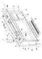
図1は、本発明に係る表示装置の全体構成図であり、図1〜3は代表的実施形態を示し、図中符号1は表示装置、2は筐体、3はダクト部材、4は送風手段、5は流通路をそれぞれ示している。 FIG. 1 is an overall configuration diagram of a display device according to the present invention. FIGS. 1 to 3 show typical embodiments. Reference numeral 1 is a display device, 2 is a housing, 3 is a duct member, and 4 is a blower.
本発明の表示装置1は、筐体2内に表示器10が内装され、前記筐体2を内気密閉構造とするとともに、外気に接する筐体壁20における内部空間側の面に沿って、当該筐体壁内面20aに接する流通路5を形成するダクト部材3を配設し、内気を導入する導入口31から内部空間に放出する排出口32に至る前記流通路5に、内気を強制的に流通させるための送風手段4を設け、導入された内気の熱を当該流通路5に臨む筐体壁20を通じて外気中に放熱してなることを特徴としている。尚、以下の実施形態では駅構内や空港ロビー等において天井から吊り下げられる行先表示装置を例示しているが、その他の案内看板や広告看板等であってもよく、また、支柱等を介して床面に載置されたり壁面に取り付けたり、様々な設置態様が可能である。 In the display device 1 of the present invention, a
前記筐体2は方形の箱体形状に構成され、筐体壁20を構成している前板21及び後板22には、それぞれ表示器10に対応する表示欄11が設けられており、同じく筐体壁20を構成する天板23、左右側板24、25および底板26の内面側に沿って、前記ダクト部材3がそれぞれ配設されている。
前記筐体壁20を構成する各板やダクト部材3は、アルミニウム又はアルミニウム合金より構成され、好ましくはAl−Mg系アルミニウム合金のA5052 H14、H34(高力アルミニウム合金)が用いられ、接着剤とリベット接合を併用して組み立てられている。The
Each plate and
前記表示器10は、文字や画像を表示するための発光ダイオードよりなるLEDモジュールで構成され、表示欄11を有する前板21及び後板22の内側近傍に平行に立設した隔壁14、14にそれぞれ固定されている。尚、表示器10及び表示欄11は、筐体2の前後片側面にのみ設けてもよい。また、表示器10はLEDモジュールに何ら限定されず、有機EL素子からなる表示器や液晶表示器その他の従来からの表示器も採用できる。 The
また、前記隔壁14に対し所定間隔をおいた内側の所定位置には、別途隔壁15が立設され、該隔壁15に、前記表示器10に対して電力を供給するための電源ユニット12や表示内容を制御するための制御器13などが配設されている。尚、表示器10や電源ユニット12、制御器13等が配設されるこれら隔壁14、15には、適宜スリット穴や切欠部を形成したり複数の分割板で構成することにより、各部への通気性を向上させることが好ましい実施例である。 Separately, a
前記ダクト部材3は、断面視略コ字形又は略半円形の部材であり、前後両端縁に沿って形成されたフランジ部30、30を筐体壁内面20aに対して接着剤やリベット接合、溶接等で固定することにより、対面する当該内面20aとの間の中空部に流通路5が形成される。このようなダクト部材3は、天板23、左右側板24、25および底板26の内面側に沿って、互いに端部を連結して連続的に配置されており、これら上下左右の筐体内面に沿って環状の流通路5が構成されている。尚、各ダクト部材3の流通路5が連通するように多少の間隔をあけて配置しても良く、また、一部又は全体を一体形成した部材を用いてもよい。 The
本例では各面の略中央部に真直なダクト部材3が配設されているが、斜め方向に沿って配したり、屈曲したジグザグ状又は曲線状に構成したダクト部材を各面に配することにより流路長さを稼いだり、複数のダクト部材を並設して流通路を複数設けることや、流通路が複数に分岐したり或いは合流するようなダクト部材を設けることも好ましい。また、本例では上下左右の4面にそれぞれダクト部材3を配して環状の流通路が構成されているが、前板又は後板にダクト部材を配することもでき、また、一面又は二面若しくは三面にのみダクト部材を設けたものであっても良い。 In this example, the
天板23内面側のダクト部材3には、流通路5に内気を導入するための導入口31、31が開設されており、各導入口31には、内気を強制的に導入する送風手段4として電動ファン40が設けられている。一方、底板26内面側のダクト部材3の前壁及び後壁には、それぞれ前板21及び後板22の内面側に配設される表示器10に対して内気を放出させる排出口32が開設されている。そして、筐体内部で昇温されて上昇した内気が前記導入口31から流通路5内に導入され、流通過程で筐体壁により熱を奪われ冷やされた内気が前記排出口32から内部空間に再度放出されることにより表示器などの熱を奪い、当該内部機器の温度上昇が抑えられるのである。 The
排出口32は、ダクト部材3の左右長手方向に沿って、所定間隔おきに複数開設されており、排出口32から放出された内気は、上記隔壁14の下端部に形成された通孔14aを通じて当該隔壁14と前板21又は後板22との間の隙間を表示器10等の熱を奪いながら上昇する流路60と、隔壁14より内側の空間を上昇する流路61とに分岐される。 A plurality of
前記隔壁14は、上記通孔14aを有するベース板16と、その上端に蝶番18を介して連結される支持板17とより構成され、表示器10が固定された当該支持板17は前記蝶番18を介して前後に開閉可能に構成されている。また、表示欄11を備えた前板21及び後板22も、それぞれ天板23の前縁部及び後縁部に蝶番19を介して連結され、同じく前後に開閉可能に構成されている。したがって保守点検等の際には、前記前板21又は後板22の下端側を持ち上げて外方に開くことにより表示器10等の保守点検等を行うことが可能となり、更に、支持板17の上端側を外方に引いて開くことにより、隔壁15に設けられている電源ユニット12や制御器13等の保守点検等が可能となる。 The
隔壁14により内側に分岐された流路61は、さらに隔壁15によって外側の流路62と内側の流路63とに分岐される。これら流路60、62、63を流通する内気は、表示器10や電源ユニット12、制御器13等の熱を奪いつつ、それぞれ隔壁14上端と天板23との隙間や隔壁15上端と天板23との隙間、隔壁14、15自体に形成される隙間などを介して合流し、再び電動ファン40により流通路5内に強制的に導入され、ダクト内で筐体壁20により熱を奪われた後、再び冷気となって上記排出口32から内部空間に放出されるといった循環が繰り返されるのである。 The
表示装置1は、さらに筐体2内を貫通し、両端部が筐体外部に開放された外気流通用の管状体7が設けられており、該管状体7の管壁は前記流通路5内に突出している。そして、流通路5内の内気は、上述のごとく筐体壁内面20aで熱を奪われるとともに、前記突出している管壁70を通じて熱を奪われ、管内部を流通する外気中にその熱が放出されることになる。このような管状体7壁面を流通路5内に突出させることは、当該流通路5内に臨む外気と接する壁内面の表面積を増大させることなり、これにより流通路5内の内気冷却効率を向上させることになるのである。更に、管状体7壁面はダクト部材3を貫通しているため、当該管状体7壁面に接するダクト部材3を通じて、流通路内の内気の熱が効率的に筒状体7内部の外気中に放出されることになる。尚、図中符号74は、底板26に被着される前記管状体7開口端部のフィルター部材であり、管状体7への埃等の侵入を防止するためのものである。 The display device 1 is further provided with a
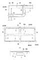
このような表面積増大により冷却効率を向上させる構造は、本例の構造に何ら限定されず、例えば図4(a)、(b)に示すように、筐体壁20の一部を流通路5内部に突出するように凹陥部71を設けたものや、逆に外方に突出した突出部72を設けることも好ましい。突出部72を設けて表面積増大を図る応用例としては、図5に示すように、筐体外部に突出する管状体73の両端を流通路5に連通させてバイパス路を形成してなるものも好ましい実施例である。また、本実施形態は天板23及び底板26間の内部空間に上下に管状体7を貫通させたものであるが、図6(a)に示すように、例えば屈曲した管状体7を天板23及び側板24(25)間に設けたものや、他の筐体壁から他の筐体壁へ連通させたものであってもよく、図6(b)に示すように三以上の筐体壁外面に連通するものも好ましい。 Such a structure for improving the cooling efficiency by increasing the surface area is not limited to the structure of this example. For example, as shown in FIGS. It is also preferable to provide a
また、流通路5の流通方向に対して直角に貫通するものにも何ら限定されず、例えば図6(c)に示すように流通方向に沿った管状体の壁面を一部又は全部突出させたものや、斜め或いは曲線的に貫通するものであってもよい。
更に、両端を筐体壁外面に連通させたもの以外に、図7(a)(b)に例示するように、ダクト部材を貫通した後、内部空間の途中部で閉塞された筒状体7を設けたものや、図7(c)に示すように筐体壁20の外面に突出させたものも好ましい実施例である。Moreover, it does not limit at all to what penetrates at right angles with the distribution direction of the
Further, in addition to the case in which both ends communicate with the outer surface of the housing wall, as illustrated in FIGS. 7A and 7B, the
前記管状体7の管壁は流通路内部以外の内気にも接しており、当該内気の熱を奪って内気を冷却する効果も奏しており、この点に着目して、例えば図8に示すように、管状体7を螺旋状に形成して内気と接する表面積を増大させることも好ましい実施例である。 The tube wall of the
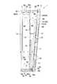
また、本実施形態は、流通路を貫通して、その一端が筐体壁20外面に開口するとともに他端が内部空間に開放される方形の筒体80を配設し、筐体壁外面の開口部80aに、一端閉塞された筒状体8の開口部を略一致させて内気が連通する状態に密着させて取り付けられている。このように筐体外部に突設した筒状体8に内気を流通させることにより、当該筒壁を通じて内気の熱を外気中に放熱させることができるのである。前記筒状体8は、本例では表示装置1全体を天井から吊り下げるための吊りパイプである。 Further, the present embodiment is provided with a
1 表示装置
2 筐体
3 ダクト部材
4 送風手段
5 流通路
7 管状体
8 筒状体
10 表示器
11 表示欄
12 電源ユニット
13 制御器
14 隔壁
14a 通孔
15 隔壁
16 ベース板
17 支持板
18、19 蝶番
20 筐体壁
20a 内面
21 前板
22 後板
23 天板
24、25 側板
26 底板
30 フランジ部
31 導入口
32 排出口
40 電動ファン
60、61、62、63 流路
70 管壁
71 凹陥部
72 突出部
73 管状体
80 筒体
80a 開口部
DESCRIPTION OF SYMBOLS 1
Claims (9)
Translated fromJapaneseThe display device according to claim 1, wherein the housing wall is made of aluminum or an aluminum alloy.
Priority Applications (1)
| Application Number | Priority Date | Filing Date | Title |
|---|---|---|---|
| JP2003424359AJP3685200B2 (en) | 2003-12-22 | 2003-12-22 | Display device |
Applications Claiming Priority (1)
| Application Number | Priority Date | Filing Date | Title |
|---|---|---|---|
| JP2003424359AJP3685200B2 (en) | 2003-12-22 | 2003-12-22 | Display device |
Publications (2)
| Publication Number | Publication Date |
|---|---|
| JP2005181799Atrue JP2005181799A (en) | 2005-07-07 |
| JP3685200B2 JP3685200B2 (en) | 2005-08-17 |
Family
ID=34784578
Family Applications (1)
| Application Number | Title | Priority Date | Filing Date |
|---|---|---|---|
| JP2003424359AExpired - Fee RelatedJP3685200B2 (en) | 2003-12-22 | 2003-12-22 | Display device |
Country Status (1)
| Country | Link |
|---|---|
| JP (1) | JP3685200B2 (en) |
Cited By (22)
| Publication number | Priority date | Publication date | Assignee | Title |
|---|---|---|---|---|
| JP2008310137A (en)* | 2007-06-15 | 2008-12-25 | Kyosan Electric Mfg Co Ltd | Support tool for guide display unit, and installation method therefor |
| JP2008310140A (en)* | 2007-06-15 | 2008-12-25 | Kyosan Electric Mfg Co Ltd | Guide display unit |
| WO2010007821A1 (en)* | 2008-07-17 | 2010-01-21 | 日本電気株式会社 | Electronic apparatus, image display, and method of cooling electronic apparatus |
| JP2010085781A (en)* | 2008-09-30 | 2010-04-15 | Sanyo Electric Co Ltd | Image display device |
| JP2010175851A (en)* | 2009-01-29 | 2010-08-12 | Sanyo Electric Co Ltd | Image display apparatus |
| JP2010175852A (en)* | 2009-01-29 | 2010-08-12 | Sanyo Electric Co Ltd | Image display apparatus |
| JP2011022362A (en)* | 2009-07-16 | 2011-02-03 | Sanyo Electric Co Ltd | Image display apparatus |
| JP2011075819A (en)* | 2009-09-30 | 2011-04-14 | Sanyo Electric Co Ltd | Image display device |
| JP2011180182A (en)* | 2010-02-26 | 2011-09-15 | Sanyo Electric Co Ltd | Electronic signboard |
| JP2012185322A (en)* | 2011-03-04 | 2012-09-27 | Sharp Corp | Multi-display system and display |
| JP2014512024A (en)* | 2011-04-01 | 2014-05-19 | サムスン エレクトロニクス カンパニー リミテッド | Display device |
| JP2015169851A (en)* | 2014-03-07 | 2015-09-28 | 株式会社新陽社 | guide display device |
| US12096607B1 (en) | 2019-02-26 | 2024-09-17 | Manufacturing Resources International, Inc. | Display assembly with loopback cooling |
| US12108546B1 (en) | 2022-07-25 | 2024-10-01 | Manufacturing Resources International, Inc. | Electronic display assembly with fabric panel communications box |
| US12108562B2 (en) | 2008-03-03 | 2024-10-01 | Manufacturing Resources International, Inc. | Electronic display with cooling |
| US12127383B2 (en) | 2007-11-16 | 2024-10-22 | Manufacturing Resources International, Inc. | Electronic display assembly with thermal management |
| US12185513B2 (en) | 2021-11-23 | 2024-12-31 | Manufacturing Resources International, Inc. | Display assembly with divided interior space |
| US12193187B2 (en) | 2022-07-22 | 2025-01-07 | Manufacturing Resources International, Inc. | Self-contained electronic display assembly, mounting structure and methods for the same |
| US12200877B2 (en) | 2020-10-23 | 2025-01-14 | Manufacturing Resources International, Inc. | Display assemblies incorporating electric vehicle charging equipment |
| US12222592B2 (en) | 2022-07-22 | 2025-02-11 | Manufacturing Resources International, Inc. | Self-contained electronic display assembly, mounting structure and methods for the same |
| US12271229B2 (en) | 2019-04-03 | 2025-04-08 | Manufacturing Resources International, Inc. | Electronic display assembly with a channel for ambient air in an access panel |
| US12314093B2 (en) | 2021-07-28 | 2025-05-27 | Manufacturing Resources International, Inc. | Display assemblies for providing compressive forces at electronic display layers |
- 2003
- 2003-12-22JPJP2003424359Apatent/JP3685200B2/ennot_activeExpired - Fee Related
Cited By (33)
| Publication number | Priority date | Publication date | Assignee | Title |
|---|---|---|---|---|
| JP2008310140A (en)* | 2007-06-15 | 2008-12-25 | Kyosan Electric Mfg Co Ltd | Guide display unit |
| JP2008310137A (en)* | 2007-06-15 | 2008-12-25 | Kyosan Electric Mfg Co Ltd | Support tool for guide display unit, and installation method therefor |
| US12207452B2 (en) | 2007-11-16 | 2025-01-21 | Manufacturing Resources International, Inc. | Electronic display assembly with thermal management |
| US12207453B1 (en) | 2007-11-16 | 2025-01-21 | Manufacturing Resources International, Inc. | Electronic display assembly with thermal management |
| US12127383B2 (en) | 2007-11-16 | 2024-10-22 | Manufacturing Resources International, Inc. | Electronic display assembly with thermal management |
| US12185512B2 (en) | 2007-11-16 | 2024-12-31 | Manufacturing Resources International, Inc. | Electronic display assembly with thermal management |
| US12207438B2 (en) | 2008-03-03 | 2025-01-21 | Manufacturing Resources International, Inc. | Electronic display with cooling |
| US12108562B2 (en) | 2008-03-03 | 2024-10-01 | Manufacturing Resources International, Inc. | Electronic display with cooling |
| US12207437B2 (en) | 2008-03-03 | 2025-01-21 | Manufacturing Resources International, Inc. | Electronic display with cooling |
| US12274022B2 (en) | 2008-03-03 | 2025-04-08 | Manufacturing Resources International, Inc. | Electronic display with cooling |
| US20110114384A1 (en)* | 2008-07-17 | 2011-05-19 | Nec Corporation | Electronic apparatus, image display apparatus and method of cooling electronic apparatus |
| US8698010B2 (en) | 2008-07-17 | 2014-04-15 | Nec Corporation | Electronic apparatus, image display apparatus and method of cooling electronic apparatus |
| WO2010007821A1 (en)* | 2008-07-17 | 2010-01-21 | 日本電気株式会社 | Electronic apparatus, image display, and method of cooling electronic apparatus |
| JP2010085781A (en)* | 2008-09-30 | 2010-04-15 | Sanyo Electric Co Ltd | Image display device |
| US8746912B2 (en) | 2008-09-30 | 2014-06-10 | Sanyo Electric Co., Ltd. | Display device having an advertizing part |
| JP2010175852A (en)* | 2009-01-29 | 2010-08-12 | Sanyo Electric Co Ltd | Image display apparatus |
| JP2010175851A (en)* | 2009-01-29 | 2010-08-12 | Sanyo Electric Co Ltd | Image display apparatus |
| JP2011022362A (en)* | 2009-07-16 | 2011-02-03 | Sanyo Electric Co Ltd | Image display apparatus |
| JP2011075819A (en)* | 2009-09-30 | 2011-04-14 | Sanyo Electric Co Ltd | Image display device |
| JP2011180182A (en)* | 2010-02-26 | 2011-09-15 | Sanyo Electric Co Ltd | Electronic signboard |
| JP2012185322A (en)* | 2011-03-04 | 2012-09-27 | Sharp Corp | Multi-display system and display |
| KR101791914B1 (en)* | 2011-04-01 | 2017-11-01 | 삼성전자주식회사 | Display apparatus |
| US9301435B2 (en) | 2011-04-01 | 2016-03-29 | Samsung Electronics Co., Ltd. | Display apparatus |
| JP2014512024A (en)* | 2011-04-01 | 2014-05-19 | サムスン エレクトロニクス カンパニー リミテッド | Display device |
| JP2015169851A (en)* | 2014-03-07 | 2015-09-28 | 株式会社新陽社 | guide display device |
| US12096607B1 (en) | 2019-02-26 | 2024-09-17 | Manufacturing Resources International, Inc. | Display assembly with loopback cooling |
| US12271229B2 (en) | 2019-04-03 | 2025-04-08 | Manufacturing Resources International, Inc. | Electronic display assembly with a channel for ambient air in an access panel |
| US12200877B2 (en) | 2020-10-23 | 2025-01-14 | Manufacturing Resources International, Inc. | Display assemblies incorporating electric vehicle charging equipment |
| US12314093B2 (en) | 2021-07-28 | 2025-05-27 | Manufacturing Resources International, Inc. | Display assemblies for providing compressive forces at electronic display layers |
| US12185513B2 (en) | 2021-11-23 | 2024-12-31 | Manufacturing Resources International, Inc. | Display assembly with divided interior space |
| US12193187B2 (en) | 2022-07-22 | 2025-01-07 | Manufacturing Resources International, Inc. | Self-contained electronic display assembly, mounting structure and methods for the same |
| US12222592B2 (en) | 2022-07-22 | 2025-02-11 | Manufacturing Resources International, Inc. | Self-contained electronic display assembly, mounting structure and methods for the same |
| US12108546B1 (en) | 2022-07-25 | 2024-10-01 | Manufacturing Resources International, Inc. | Electronic display assembly with fabric panel communications box |
Also Published As
| Publication number | Publication date |
|---|---|
| JP3685200B2 (en) | 2005-08-17 |
Similar Documents
| Publication | Publication Date | Title |
|---|---|---|
| JP3685200B2 (en) | Display device | |
| KR101494856B1 (en) | A LCD Installation Frame for the Bus Shelter | |
| CN110573946B (en) | display screen | |
| US8072752B2 (en) | Electrical cabinet with two cooling channels | |
| JP5723036B2 (en) | Battery cooling system and battery rack applied to the same | |
| KR20040019187A (en) | A case for covering electronic parts and a displaying apparatus having it | |
| JP2006064303A (en) | Computer room air conditioning and system exhaust guidance system | |
| CN102668546A (en) | Radiation unit of electronic device and electronic device using same | |
| EP2613078B1 (en) | Light source apparatus and cooling thereof | |
| JP2011014715A (en) | Heat radiating unit and electronic component using the same | |
| JP6683487B2 (en) | refrigerator | |
| JP2008209464A (en) | Projector device | |
| US20070030651A1 (en) | Instrument cabinet | |
| JP2005294456A (en) | Power apparatus control board and power source device | |
| KR101441622B1 (en) | Stand type kiosk having heat dissipation structure of natural ventilation and exhaustion | |
| JP6678482B2 (en) | Station information display | |
| SE9700814L (en) | Refrigerated | |
| JP2013218257A (en) | Electronic apparatus | |
| JP2008209463A (en) | Projector device | |
| JP5434713B2 (en) | Heat dissipation unit and electronic device using the same | |
| JPH0697688A (en) | Cooling structure of electronic device | |
| JP2011119424A (en) | Heat radiation unit and electronic apparatus using the same | |
| JP6242169B2 (en) | Control panel and pump device | |
| JP2006261215A (en) | Heat dissipation structure of electronic apparatus | |
| JP2008003263A (en) | Power supply unit for projection display device and projection display device including the same |
Legal Events
| Date | Code | Title | Description |
|---|---|---|---|
| A521 | Request for written amendment filed | Free format text:JAPANESE INTERMEDIATE CODE: A523 Effective date:20050415 | |
| TRDD | Decision of grant or rejection written | ||
| A01 | Written decision to grant a patent or to grant a registration (utility model) | Free format text:JAPANESE INTERMEDIATE CODE: A01 Effective date:20050510 | |
| A61 | First payment of annual fees (during grant procedure) | Free format text:JAPANESE INTERMEDIATE CODE: A61 Effective date:20050523 | |
| R150 | Certificate of patent or registration of utility model | Ref document number:3685200 Country of ref document:JP Free format text:JAPANESE INTERMEDIATE CODE: R150 Free format text:JAPANESE INTERMEDIATE CODE: R150 | |
| FPAY | Renewal fee payment (event date is renewal date of database) | Free format text:PAYMENT UNTIL: 20080610 Year of fee payment:3 | |
| FPAY | Renewal fee payment (event date is renewal date of database) | Free format text:PAYMENT UNTIL: 20110610 Year of fee payment:6 | |
| R250 | Receipt of annual fees | Free format text:JAPANESE INTERMEDIATE CODE: R250 | |
| FPAY | Renewal fee payment (event date is renewal date of database) | Free format text:PAYMENT UNTIL: 20110610 Year of fee payment:6 | |
| FPAY | Renewal fee payment (event date is renewal date of database) | Free format text:PAYMENT UNTIL: 20120610 Year of fee payment:7 | |
| R250 | Receipt of annual fees | Free format text:JAPANESE INTERMEDIATE CODE: R250 | |
| FPAY | Renewal fee payment (event date is renewal date of database) | Free format text:PAYMENT UNTIL: 20120610 Year of fee payment:7 | |
| FPAY | Renewal fee payment (event date is renewal date of database) | Free format text:PAYMENT UNTIL: 20130610 Year of fee payment:8 | |
| R250 | Receipt of annual fees | Free format text:JAPANESE INTERMEDIATE CODE: R250 | |
| FPAY | Renewal fee payment (event date is renewal date of database) | Free format text:PAYMENT UNTIL: 20140610 Year of fee payment:9 | |
| R250 | Receipt of annual fees | Free format text:JAPANESE INTERMEDIATE CODE: R250 | |
| R250 | Receipt of annual fees | Free format text:JAPANESE INTERMEDIATE CODE: R250 | |
| R250 | Receipt of annual fees | Free format text:JAPANESE INTERMEDIATE CODE: R250 | |
| R250 | Receipt of annual fees | Free format text:JAPANESE INTERMEDIATE CODE: R250 | |
| R250 | Receipt of annual fees | Free format text:JAPANESE INTERMEDIATE CODE: R250 | |
| R250 | Receipt of annual fees | Free format text:JAPANESE INTERMEDIATE CODE: R250 | |
| R250 | Receipt of annual fees | Free format text:JAPANESE INTERMEDIATE CODE: R250 | |
| R250 | Receipt of annual fees | Free format text:JAPANESE INTERMEDIATE CODE: R250 | |
| R250 | Receipt of annual fees | Free format text:JAPANESE INTERMEDIATE CODE: R250 | |
| R250 | Receipt of annual fees | Free format text:JAPANESE INTERMEDIATE CODE: R250 | |
| LAPS | Cancellation because of no payment of annual fees |