JP2005181114A - Leading vehicle detection device and control method thereof - Google Patents
Leading vehicle detection device and control method thereofDownload PDFInfo
- Publication number
- JP2005181114A JP2005181114AJP2003422560AJP2003422560AJP2005181114AJP 2005181114 AJP2005181114 AJP 2005181114AJP 2003422560 AJP2003422560 AJP 2003422560AJP 2003422560 AJP2003422560 AJP 2003422560AJP 2005181114 AJP2005181114 AJP 2005181114A
- Authority
- JP
- Japan
- Prior art keywords
- laser radar
- scanning laser
- host vehicle
- calculated
- point
- Prior art date
- Legal status (The legal status is an assumption and is not a legal conclusion. Google has not performed a legal analysis and makes no representation as to the accuracy of the status listed.)
- Granted
Links
Images


Landscapes
- Traffic Control Systems (AREA)
- Optical Radar Systems And Details Thereof (AREA)
- Control Of Driving Devices And Active Controlling Of Vehicle (AREA)
- Controls For Constant Speed Travelling (AREA)
Abstract
Translated fromJapaneseDescription
Translated fromJapanese本発明は、スキャニングレーザレーダを用いて自車両前方の先行車両を検出する先行車両検出装置及びその制御方法に関する。 The present invention relates to a preceding vehicle detection device that detects a preceding vehicle ahead of the host vehicle using a scanning laser radar and a control method therefor.
従来、スキャニングレーザレーダを用いた先行車両検出装置が知られている。スキャニングレーザレーダは、自車両前方をレーザ光により所定のスキャン幅でスキャンして先行車両を検出するものであり、このようなスキャニングレーザレーダを用いた先行車両検出装置は、例えば、自車両を先行車両に対して所定の車間距離で追従させる自動追従走行を実現するものとして、実用化に向けての技術開発が様々な観点からなされている。 Conventionally, a preceding vehicle detection device using a scanning laser radar is known. The scanning laser radar scans the front of the host vehicle with a laser beam with a predetermined scan width to detect a preceding vehicle. The preceding vehicle detection device using such a scanning laser radar, for example, precedes the host vehicle. Technological development for practical use has been made from various viewpoints as a means for realizing automatic follow-up traveling that follows a vehicle at a predetermined inter-vehicle distance.
この種の先行車両検出装置で自動追従走行を実現する上で、特に重要な課題とされているのは、カーブ路走行における先行車両の検出精度向上である。カーブ路走行においては、先行車両がカーブに沿って先行したときに、その位置が自車両の走行方向前方から大きくずれてスキャニングレーザレーダのスキャン領域から外れ、先行車両を見失うことも想定される。 In realizing automatic follow-up running with this type of preceding vehicle detection device, it is particularly important to improve the accuracy of detection of the preceding vehicle in curve road running. In traveling on a curved road, when the preceding vehicle has advanced along the curve, it is assumed that the position of the preceding vehicle deviates greatly from the front in the traveling direction of the host vehicle and deviates from the scanning area of the scanning laser radar, and the preceding vehicle is lost.
そこで、このようなカーブ路走行での走行車両の検出精度を向上させるべく、前方カメラで撮像された画像から自車両前方の道路形状を判定し、自車両前方の道路がカーブ路の場合にはその曲率に応じてスキャニングレーザレーダのスキャン幅中心を補正することで、カーブに沿って先行する先行車両を検出できるようにする技術が提案されている(例えば、特許文献1参照。)。 Therefore, in order to improve the detection accuracy of the traveling vehicle on such a curved road, the road shape ahead of the host vehicle is determined from the image captured by the front camera, and the road ahead of the host vehicle is a curved road. A technique has been proposed in which the preceding vehicle preceding the curve can be detected by correcting the scanning width center of the scanning laser radar according to the curvature (see, for example, Patent Document 1).
この特許文献1に記載の技術では、前回の処理で検出された先行車両が今回の処理で検出されなくなった場合で、ステアリング操作を行っていない場合には、先行車両がカーブ路を走行中であるためにスキャニングレーザレーダのスキャン領域から外れたものと判定している。そして、このような場合には、前方カメラで撮像された画像から前方カーブ路の曲率を求め、それに基づき自車両前方の直線上からの先行車両の位置のずれ量を予測して、このずれ量に応じてスキャニングレーザレーダのスキャン幅中心を補正するようにしている。
しかしながら、上述した特許文献1に記載された技術では、スキャニングレーザレーダのスキャン幅中心を実際に補正する際の動作に要する時間が考慮されていないため、例えば曲率が不規則に変動するようなカーブ路等においては、先行車両の検出を適切に行えない虞がある。すなわち、補正量を算出してから実際にアクチュエータ等によりスキャニングレーザレーダのスキャン幅中心を補正するまでの間にはアクチュエータの性能等に応じたタイムラグが生じるが、この間も自車両及び先行車両は走行を継続しているため、実際にスキャニングレーザレーダのスキャン幅中心が補正されたときには、先行車両が予測位置とは異なる位置に移動してスキャニングレーザレーダのスキャン領域から外れてしまうといった問題が生じる。 However, in the technique described in
本発明は、以上のような従来技術の有する問題点を解消すべく創案されたものであって、最適なタイミングでスキャニングレーザレーダのスキャン幅中心を適切に変化させることができ、様々な道路状況に応じて先行車両の検出を高精度に行うことが可能な先行車両検出装置及びその制御方法を提供することを目的としている。 The present invention was devised to solve the above-described problems of the prior art, and can appropriately change the scan width center of the scanning laser radar at an optimal timing. It is an object of the present invention to provide a preceding vehicle detection device and a control method thereof that can detect the preceding vehicle with high accuracy in accordance with the above.
本発明に係る先行車両検出装置は、スキャニングレーザレーダを用いて自車両前方の先行車両を検出するものであり、スキャニングレーザレーダのスキャン幅中心をアクチュエータの動作で変化させることができるようにしている。そして、アクチュエータの動作を制御するアクチュエータ制御部が、目標地点算出手段、目標変化量算出手段、動作所要時間算出手段、経過走行距離算出手段の各手段を有している。 The preceding vehicle detection device according to the present invention detects a preceding vehicle ahead of the host vehicle using a scanning laser radar, and can change the scan width center of the scanning laser radar by the operation of the actuator. . The actuator control unit that controls the operation of the actuator includes a target point calculation unit, a target change amount calculation unit, an operation required time calculation unit, and an elapsed travel distance calculation unit.
このような構成の本発明に係る先行車両検出装置では、アクチュエータ制御部の目標地点算出手段により、スキャニングレーザレーダのスキャン幅中心を変化させる必要がある地点が算出され、目標変化量算出手段により、この地点で必要とされるスキャニングレーザレーダのスキャン幅中心の変化量が算出される。また、動作所要時間算出手段により、アクチュエータがスキャニングレーザレーダのスキャン幅中心を前記変化量だけ変化させるのに要する時間がアクチュエータの可動速度に基づいて算出され、経過走行距離算出手段により、この時間で自車両が走行する距離が自車両の走行速度に基づいて算出される。そして、アクチュエータ制御部は、自車両が目標地点算出手段により算出された地点から経過走行距離算出手段により算出された距離分だけ手前の地点に到達した段階で、アクチュエータの動作を開始させる。したがって、自車両が目標地点算出手段により算出された地点に到達したときには、スキャン幅中心を変化させる動作が完了した状態で、スキャニングレーザレーダにより所望の領域を対象としたスキャンが実施されることになる。 In the preceding vehicle detection device according to the present invention having such a configuration, a point where the scan width center of the scanning laser radar needs to be changed is calculated by the target point calculation unit of the actuator control unit, and the target change amount calculation unit The amount of change at the center of the scanning width of the scanning laser radar required at this point is calculated. Further, the time required for the actuator to change the scan width center of the scanning laser radar by the amount of change is calculated based on the moving speed of the actuator, and the elapsed travel distance calculating means The distance traveled by the host vehicle is calculated based on the traveling speed of the host vehicle. Then, the actuator control unit starts the operation of the actuator when the host vehicle reaches a point in front of the distance calculated by the elapsed travel distance calculating unit from the point calculated by the target point calculating unit. Therefore, when the host vehicle reaches the point calculated by the target point calculating means, the scanning for the desired region is performed by the scanning laser radar with the operation for changing the center of the scan width being completed. Become.
また、本発明に係る先行車両検出装置の制御方法は、スキャニングレーザレーダのスキャン幅中心をアクチュエータの動作で変化させることができるようにした先行車両検出装置の制御方法であり、スキャニングレーザレーダのスキャン幅中心を変化させる必要がある地点を算出する第1のステップと、この第1のステップで算出された地点で必要とされるスキャニングレーザレーダのスキャン幅中心の変化量を算出する第2のステップと、アクチュエータの可動速度に基づいて、アクチュエータがスキャニングレーザレーダのスキャン幅中心を第2のステップで算出された変化量だけ変化させるのに要する時間を算出する第3のステップと、自車両の走行速度に基づいて、第3のステップで算出された時間で自車両が走行する距離を算出する第4のステップと、自車両が第1のステップで算出された地点から第4のステップで算出された距離分だけ手前の地点に到達した段階で、アクチュエータの動作を開始させる第5のステップとを有することを特徴としている。 The preceding vehicle detection device control method according to the present invention is a preceding vehicle detection device control method in which the scanning width center of the scanning laser radar can be changed by the operation of the actuator. A first step for calculating a point where the width center needs to be changed, and a second step for calculating a change amount of the scanning width center of the scanning laser radar required at the point calculated in the first step And a third step of calculating a time required for the actuator to change the scan width center of the scanning laser radar by the amount of change calculated in the second step based on the moving speed of the actuator; Based on the speed, the distance traveled by the vehicle in the time calculated in the third step is calculated. A fourth step, and a fifth step in which the operation of the actuator is started when the host vehicle reaches the previous point by the distance calculated in the fourth step from the point calculated in the first step. It is characterized by having.
本発明によれば、アクチュエータによりスキャニングレーザレーダのスキャン幅中心を変化させる動作が最適なタイミングで実行され、スキャニングレーザレーダのスキャン幅中心を変化させる必要がある地点に自車両が到達したときには、スキャン幅中心を変化させる動作が完了した状態で所望の領域を対象としたスキャンが実施されるので、様々な道路状況に対応して、常に高精度に先行車両の検出を行うことができる。 According to the present invention, the operation of changing the scan width center of the scanning laser radar by the actuator is executed at an optimal timing, and when the host vehicle reaches the point where the scan width center of the scanning laser radar needs to be changed, the scan is performed. Since the scan for the desired region is performed in a state where the operation for changing the width center is completed, it is possible to always detect the preceding vehicle with high accuracy corresponding to various road conditions.
以下、本発明の具体的な実施形態について、図面を参照しながら詳細に説明する。 Hereinafter, specific embodiments of the present invention will be described in detail with reference to the drawings.
(第1の実施形態)
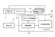
本発明を適用した先行車両検出装置の一構成例を図1に示す。この図1に示す先行車両検出装置は、スキャニングレーザレーダ1を用いて自車両前方を走行する先行車両を検出するものであり、特に、道路曲率が変化するカーブ路をはじめ、様々な道路状況に対応して高精度な検出を行えるようにしたものである。(First embodiment)
A configuration example of a preceding vehicle detection apparatus to which the present invention is applied is shown in FIG. The preceding vehicle detection device shown in FIG. 1 detects a preceding vehicle that travels ahead of the host vehicle using the
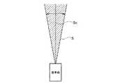
スキャニングレーザレーダ1は、自車両前方に向けて出射したレーザ光が物体にて反射されて戻ってくるまでの経過時間に基づいて、自車両前方の物体までの距離を測定するものであり、レーザ光の出射角度を所定範囲で振りながらレーザ光の出射を微小間隔で連続的に行うことで、図2に示すように、自車両前方の所定の領域をレーザ光によりスキャンできるようにしたものである。このスキャニングレーザレーダ1でスキャンされる自車両前方の領域は、レーザ光の出射角度が振られる範囲に対応しており、ここでは、その領域をスキャン幅Sと呼び、その中心をスキャン幅中心Scと呼ぶ。 The
このスキャニングレーザレーダ1のスキャン幅中心Scは、アクチュエータ2の動作により可変とされている。直線道路走行中においては、自車両前方の直線上を先行車両が走行しているので、自車両の向きに沿った延長線上をスキャニングレーザレーダ1のスキャン幅中心Scとしておけばよいが、自車両がカーブ路手前に差し掛かったときやカーブ路走行中では、先行車両が自車両の向きに沿った延長線上から左右に変位した位置を走行することになるので、先行車両を確実に検出するためには、スキャニングレーザレーダ1のスキャン幅中心Scを先行車両が走行している方向へと変化させる必要が生じる。そこで、本発明を適用した先行車両検出装置では、道路状況に応じて必要があると判断したときには、アクチュエータ2がスキャニングレーザレーダ1のスキャン幅中心Sc(詳しくは、自車両に対するスキャン幅中心Scの向き)を変化させるようにしている。このアクチュエータ2の動作は、詳細を後述するが、コントローラ10のアクチュエータ制御部11によって制御される。 The scan width center Sc of the
また、本発明を適用した先行車両検出装置では、スキャニングレーザレーダ1の他に、自車両前方の画像を撮像する前方カメラ3を備えている。この前方カメラ3で撮像された自車両前方の画像は、コントローラ10の画像処理部11に送られてここで処理される。この画像処理部11における画像処理によって、自車両前方の道路形状等が認識されることになる。 In addition to the
また、コントローラ10は、先行車両判定部13を有している。この先行車両判定部13は、スキャニングレーザレーダ1の測定結果と、画像処理部11の処理結果とから、自車両前方の先行車両の有無や、先行車両がいる場合にはその先行車両の方位や自車両との車間距離等を判定する。 The
以上が本発明を適用した先行車両検出装置の基本構成であるが、この先行車両検出装置では、特にコントローラ10のアクチュエータ制御部11の処理に大きな特徴を有しており、アクチュエータ制御部11が以下のような処理を行ってアクチュエータ2を動作させることで、最適なタイミングでスキャニングレーザレーダ2のスキャン幅中心を適切に変化させ、様々な道路状況に応じて先行車両の検出を高精度に行えるようにしている。 The above is the basic configuration of the preceding vehicle detection device to which the present invention is applied. This preceding vehicle detection device has a great feature particularly in the processing of the
すなわち、本発明を適用した先行車両検出装置において、コントローラ10のアクチュエータ制御部11は、先ず、自車両前方の道路曲率の変化率に基づいて、スキャニングレーザレーダ1のスキャン幅中心Scを変化させる必要がある地点(以下、目標地点という。)を算出する(目標値点算出手段)。また、この目標地点で必要とされるスキャニングレーザレーダ1のスキャン幅中心Scの変化量(以下、目標変化量という。)を算出する(目標変化量算出手段)。ここで、自車両前方の道路曲率やその変化率は、前方カメラ3により撮像された自車両前方の画像をコントローラ10の画像処理部12で処理したデータに基づき認識される。 That is, in the preceding vehicle detection apparatus to which the present invention is applied, the
次に、アクチュエータ制御部11は、アクチュエータ2の可動速度に基づいて、アクチュエータ2がスキャニングレーザレーダ1のスキャン幅中心Scを前記目標変化量だけ変化させるのに要する時間(以下、動作所要時間という。)を算出する(動作所要時間算出手段)。ここで、アクチュエータ2の可動速度は、アクチュエータ2の性能により決まる固有のパラメータであり、アクチュエータ制御部11は、このパラメータを予め記憶しておく。 Next, the
次に、アクチュエータ制御部11は、自車両の走行速度に基づいて、前記動作所要時間で自車両が走行する距離(以下、経過走行距離という。)を算出する(走行距離算出手段)。ここで、自車両の走行速度は、自車両の左右前後輪に各々設置された車輪速センサ4の検出値に基づいて算出される。 Next, the
そして、アクチュエータ制御部11は、自車両が前記目標地点から前記経過走行距離分だけ手前の地点に到達した段階で、アクチュエータ2の動作を開始させる。これにより、自車両が目標地点に到達したときには、アクチュエータ2によるスキャニングレーザレーダ1のスキャン幅中心Scを変化させる動作が完了することになり、道路曲率に対応してスキャン幅中心Scを変化させた状態で、スキャニングレーザレーダ1により所望の領域を対象としたスキャンが実施されることになる。 Then, the
図3は、以上のようなコントローラ10のアクチュエータ制御部11により所定周期で繰り返し実行される処理の具体的な一例を示すフローチャートである。以下、このフローチャートに沿って、コントローラ10のアクチュエータ制御部11により実行される処理について、更に詳しく説明する。 FIG. 3 is a flowchart showing a specific example of the process repeatedly executed at a predetermined cycle by the
アクチュエータ制御部11は、先ず、ステップS101において、車輪速センサ4から自車両の車輪速度を示すセンサ信号を読み込むと共に、画像処理部12から、自車両が走行している走行レーンのレーン形状を示すデータや、自車両のヨー角(走行レーンに対する傾き)φrのデータ等、自車両の走行環境に関するデータを読み込む。 First, in step S101, the
次に、ステップS102において、車輪速センサ4から読み込んだセンサ信号に基づいて、下記式(1)により、自車両の走行速度Vを算出する。なお、Vrは自車両の右側車輪に取り付けられた車輪速センサ4からのセンサ信号であり、Vlは自車両の左側車輪に取り付けられた車輪速センサ4からのセンサ信号である。 Next, in step S102, based on the sensor signal read from the wheel speed sensor 4, the traveling speed V of the host vehicle is calculated by the following equation (1). Vr is a sensor signal from the wheel speed sensor 4 attached to the right wheel of the host vehicle, and Vl is a sensor signal from the wheel speed sensor 4 attached to the left wheel of the host vehicle.
V=(Vr+Vl)/2 ・・・(1)
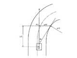
次に、ステップS103において、画像処理部12からのデータに基づき、自車両前方に等間隔で並ぶ複数の地点を前方注視点P(i:i=1〜n)としてサンプリングし、各前方注視点P(i)における走行レーンの曲率推定値ρ(i)を求める。具体的には、例えば図4に示すように、前方注視点P(i)の走行レーン境界線に対する横変位量をys(i)、走行レーン中央に対する自車両の横変位量をycr、前方注視点P(i)における走行レーンの接線に対する自車両の傾き(ヨー角)をφr、自車両から前方注視点P(i)までの距離をL(i)とすると、前方注視点P(i)における走行レーンの曲率推定値ρ(i)は、下記式(2)から求められる。V = (Vr + Vl) / 2 (1)
Next, in step S103, based on the data from the
ys(i)=ycr+L(i)・φr−L(i)2/2・ρ(i) ・・・(2)
なお、前方注視点をサンプリングする間隔は、自車両の走行速度Vやアクチュエータ2の性能、コントローラ10の処理能力等に応じて適宜設定すればよい。ys (i) = ycr + L (i) · φr-L (i) 2/2 · ρ (i) ··· (2)
In addition, what is necessary is just to set the space | interval which samples a front gaze point suitably according to the driving speed V of the own vehicle, the performance of the
次に、ステップS104において、自車両に最も近い前方注視点から順に、この前方注視点における走行レーンの曲率と、次の前方注視点における走行レーンの曲率との変化率ρa(i)を、下記式(3)により算出する。 Next, in step S104, the rate of change ρa (i) between the curvature of the traveling lane at the forward gazing point and the curvature of the traveling lane at the next forward gazing point in order from the closest forward gazing point to the host vehicle is Calculated according to equation (3).
ρa(i)=ρ(i)−ρ(i+1) ・・・(3)
次に、ステップS105において、ステップS104で算出した変化率ρa(i)が基準値α以上となっているかどうかを判定し、変化率ρa(i)が基準値α以上となっている場合には、前方注視点P(i)がスキャニングレーザレーダ1のスキャン幅中心Scを変化させる必要のある目標地点であると判断して、次のステップS106へと進む。一方、変化率ρa(i)が基準値αを下回っている場合には、ステップS111へと処理を移行する。ρa (i) = ρ (i) −ρ (i + 1) (3)
Next, in step S105, it is determined whether or not the rate of change ρa (i) calculated in step S104 is greater than or equal to the reference value α. If the rate of change ρa (i) is greater than or equal to the reference value α, Then, it is determined that the forward gazing point P (i) is a target point where the scan width center Sc of the
ステップS106では、目標地点である前方注視点P(i)において必要とされるスキャニングレーザレーダ1のスキャン幅中心Scの変化量(目標変化量)θwantを算出する。具体的には、先ず、図5に示すように、スキャニングレーザレーダ1のスキャン幅中心Scを変更しない状態で自車両が前方注視点P(i)に到達したときのスキャン幅中心Scの向き(自車両が走行レーンに沿って走行していると仮定した場合には、前方注視点P(i)における走行レーンの接線)と、前方注視点P(i)と次の前方注視点P(i+1)における走行レーン境界を結ぶ線とがなす角θlaneを求める。そして、この求めた値θlaneとスキャニングレーザレーダ1のスキャン幅Sの角度θraderとから、下記式(4)により、スキャン幅中心Scの目標変化量θwantを算出する。In step S106, the amount of change (target amount of change) θwant of the scan width center Sc of the
θwant=θlane−θrader/2 ・・・(4)
次に、ステップS107において、ステップS106で求めた目標変化量θwantとアクチュエータ2の可動速度Sとに基づいて、下記式(5)により、アクチュエータ2がスキャニングレーザレーダ1のスキャン幅中心Scを目標変化量θwant分だけ変化させるのに要する動作所要時間Tを算出する。θwant = θlane −θrader / 2 (4)
Next, in step S107, the
T=θwant/S ・・・(5)
次に、ステップS108において、ステップS102で算出した自車両の走行速度Vと、ステップS107で算出した動作所要時間Tとに基づいて、下記式(6)により、動作所要時間Tが経過する間に自車両が走行する経過走行距離Yを算出する。T =θwant / S (5)
Next, in step S108, based on the traveling speed V of the host vehicle calculated in step S102 and the required operation time T calculated in step S107, the following equation (6) indicates that the required operation time T has elapsed. The elapsed travel distance Y traveled by the host vehicle is calculated.
Y=V・T ・・・(6)
次に、ステップS109において、自車両が目標地点である前方注視点P(i)から経過走行距離Y分だけ手前の地点に到達したかどうかを判定し、到達した段階でアクチュエータ2の動作を開始させる(ステップS110)。Y = V · T (6)
Next, in step S109, it is determined whether or not the host vehicle has reached a point in front of the target point, the forward gazing point P (i), by the elapsed travel distance Y. (Step S110).
以上のステップS104からステップS110までの処理は、ステップS103においてサンプリングした各前方注視点P(n)毎にそれぞれ行われる。すなわち、ステップS111においてi=nであるかどうかが判定され、i=nでない場合、すなわち未処理の前方注視点P(i)が残されている場合には、ステップS112でiの値がインクリメントされた上でステップS104に戻り、以降の処理が繰り返し行われる。そして、最後の前方注視点P(n)に対する処理が終了した段階で、一連の処理が終了する。 The processes from step S104 to step S110 are performed for each forward gazing point P (n) sampled in step S103. That is, whether or not i = n is determined in step S111. If i = n is not satisfied, that is, if an unprocessed forward gazing point P (i) remains, the value of i is incremented in step S112. After that, the process returns to step S104, and the subsequent processing is repeated. And a series of processings are complete | finished in the stage which the process with respect to the last front gaze point P (n) was complete | finished.
なお、以上の例では、サンプリングした各前方注視点P(n)に対して、それぞれスキャニングレーザレーダ1のスキャン幅中心Scを変更する必要があるかどうかを判定するようにしているが、複数の前方注視点P(n)の中で曲率の変化率が最も大きい地点を判定してここを目標地点とし、この地点を対象とした処理のみを行うようにしてもよい。 In the above example, it is determined whether it is necessary to change the scan width center Sc of the
本発明を適用した先行車両検出装置では、コントローラ10のアクチュエータ制御部11が、以上のような一連の処理を所定周期で繰り返し実行することにより、スキャニングレーザレーダ1のスキャン幅中心Scを、道路状況に応じて常に最適な状態に保つことができ、様々な道路形状に対応して、先行車両の検出を高精度に行うことが可能となる。 In the preceding vehicle detection apparatus to which the present invention is applied, the
(第2の実施形態)
次に、本発明を適用した先行車両検出装置の他の例について説明する。本実施形態の先行車両検出装置は、基本構成を上述した第1の実施形態と同様とし、コントローラ10のアクチュエータ制御部11による処理内容が、第1の実施形態とは若干異なるものである。すなわち、本実施形態の先行車両検出装置では、自車両が複数のレーンを有する道路を走行しており、自車両の走行レーンよりも曲率の大きな内側レーンが存在する場合を想定して、そのような道路環境でのカーブ路走行における傾向をふまえて、自車両が走行している走行車線前方の先行車両を追跡しているときと、走行車線前方に先行車両が存在していないときとで、前記スキャニングレーザレーダのスキャン幅中心の変化量として、異なる値を算出するようにしている。(Second Embodiment)
Next, another example of the preceding vehicle detection device to which the present invention is applied will be described. The preceding vehicle detection device of the present embodiment has the same basic configuration as that of the first embodiment described above, and the processing content by the
本実施形態の先行車両検出装置の構成は、上述した第1の実施形態と同様であるので、ここでは図示及び詳細な説明を省略し、以下、本実施形態に特徴的なアクチュエータ制御部11による処理内容について具体的な例を挙げながら説明する。 Since the configuration of the preceding vehicle detection device of the present embodiment is the same as that of the first embodiment described above, illustration and detailed description thereof will be omitted here, and hereinafter, the
図6及び図7は、本実施形態の先行車両検出装置におけるコントローラ10のアクチュエータ制御部11により所定周期で実行される処理の具体的な一例を示すフローチャートである。 6 and 7 are flowcharts showing a specific example of processing executed at a predetermined cycle by the
本実施形態の先行車両検出装置では、コントローラ10のアクチュエータ制御部11が、先ず、ステップS201において、車輪速センサ4から自車両の車輪速度を示すセンサ信号を読み込むと共に、画像処理部12から、自車両が走行している走行レーンのレーン形状を示すデータや、自車両のヨー角(走行レーンに対する傾き)φrのデータ等、自車両の走行環境に関するデータを読み込む。 In the preceding vehicle detection device of the present embodiment, the
次に、ステップS202において、車輪速センサ4から読み込んだセンサ信号に基づいて、第1の実施形態と同様の手法で、自車両の走行速度Vを算出する。 Next, in step S202, based on the sensor signal read from the wheel speed sensor 4, the traveling speed V of the host vehicle is calculated by the same method as in the first embodiment.
次に、ステップS203において、画像処理部12からのデータに基づき、自車両が走行している走行レーンを検出する。具体的には、例えば図7(a)に示すように、自車両が3つのレーンを有する道路を走行している場合において、自車両の走行レーンが左側のレーンである場合(車両位置がAの場合)には、前方カメラ2で撮像される画像は図7(b)のようになり、画面右側に隣接レーンが現れるが画面左側には隣接レーンが認められない。また、自車両の走行レーンが中央のレーンである場合(車両位置がBの場合)には、前方カメラ2で撮像される画像は図7(c)のようになり、画面の左右に隣接レーンが現れる。また、自車両の走行レーンが右側レーンの場合(車両位置がCの場合)には、前方カメラ2で撮像される画像は図7(d)のようになり、画面左側に隣接レーンが現れるが画面右側には隣接レーンが認められない。このように、自車両が複数のレーンを有する道路を走行している場合には、自車両がどのレーンを走行しているかによって前方カメラ2で撮像される画像に違いが現れるので、前方カメラ2で撮像された画像を処理する画像処理部12からのデータを解析することで、自車両が走行している走行レーンを検出することができる。 Next, in step S203, based on the data from the
次に、ステップS204において、ステップS203で検出した走行レーンに先行車両が存在するか否か、すなわち、今回の処理が先行車両の追跡を行っている状態での処理であるかどうかを判定する。 Next, in step S204, it is determined whether or not there is a preceding vehicle in the travel lane detected in step S203, that is, whether or not the current process is a process in which the preceding vehicle is being tracked.
次に、ステップS205において、画像処理部12からのデータに基づき、自車両前方に等間隔で並ぶ複数の地点を前方注視点P(i:i=1〜n)としてサンプリングし、第1の実施形態と同様の手法で、各前方注視点P(i)における走行レーンの曲率推定値ρ(i)を求める。このとき、自車両が走行している走行レーンよりも曲率の大きい内側レーンがあるときは、この内側レーンの曲率推定値も合わせて算出する。 Next, in step S205, based on the data from the
次に、ステップS206において、自車両に最も近い前方注視点から順に、この前方注視点における走行レーンの曲率と、次の前方注視点における走行レーンの曲率との変化率ρa(i)を、第1の実施形態と同様の手法で算出する。 Next, in step S206, the rate of change ρa (i) between the curvature of the traveling lane at the forward gazing point and the curvature of the traveling lane at the next forward gazing point is determined in order from the forward gazing point closest to the host vehicle. The calculation is performed in the same manner as in the first embodiment.
次に、ステップS207において、ステップS206で算出した変化率ρa(i)が基準値α以上となっているかどうかを判定し、変化率ρa(i)が基準値α以上となっている場合には、前方注視点P(i)がスキャニングレーザレーダ1のスキャン幅中心Scを変化させる必要のある目標地点であると判断して、次のステップS208へと進む。一方、変化率ρa(i)が基準値αを下回っている場合には、ステップS213へと処理を移行する。 Next, in step S207, it is determined whether or not the rate of change ρa (i) calculated in step S206 is greater than or equal to the reference value α. If the rate of change ρa (i) is greater than or equal to the reference value α, Then, it is determined that the forward gazing point P (i) is a target point where the scan width center Sc of the
ステップS208では、目標地点である前方注視点P(i)において必要とされるスキャニングレーザレーダ1のスキャン幅中心Scの変化量(目標変化量)θwantを算出する。ここで、特に本実施形態では、図7に示すように、自車両が走行している道路に内側レーンがあるかどうか、更には内側レーンがある場合には先行車両追跡中であるかどうかによって、目標変化量θwantとして異なる値を算出するようにしている。図7は図6のステップS208での処理の詳細を示すサブルーチンであり、先ず、ステップS301において、走行レーンの内側に内側レーンがあるかどうかをステップS203での検出結果に基づいて判定する。そして、内側レーンがない場合には、ステップS302において、第1の実施形態と同様の手法で、スキャニングレーザレーダ1のスキャン幅中心Scが、走行レーンの中の内側の領域をスキャンできる向きとなるように、目標変化量θwantを算出する。In step S208, the amount of change (target amount of change) θwant of the scan width center Sc of the
一方、内側レーンがある場合には、次にステップS303において、ステップS204での判定結果に基づいて、先行車両追跡中であるかどうかを判定する。そして、先行車両追跡中である場合には、ステップS304において、スキャニングレーザレーダ1のスキャン幅中心Scが、走行レーンと内側レーンとの境界周辺の領域をスキャンできる向きとなるように、目標変化量θwantを算出する。On the other hand, if there is an inner lane, it is next determined in step S303 whether the preceding vehicle is being tracked based on the determination result in step S204. When the preceding vehicle is being tracked, in step S304, the target change amount is set such that the scan width center Sc of the
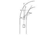
具体的には、先ず、図9に示すように、スキャニングレーザレーダ1のスキャン幅中心Scを変更しない状態で自車両が前方注視点P(i)に到達したときのスキャン幅中心Scの向きと、前方注視点P(i)と次の前方注視点P(i+1)における内側レーン中央位置を結ぶ線とがなす角θlane_centerを求める。そして、この求めた値θlane_centerとスキャニングレーザレーダ1のスキャン幅Sの角度θraderとから、下記式(7)により、スキャン幅中心Scの目標変化量θwantを算出する。Specifically, first, as shown in FIG. 9, the direction of the scan width center Sc when the host vehicle reaches the forward gazing point P (i) without changing the scan width center Sc of the
θwant=θlane_center−θrader/2 ・・・(7)
一方、ステップS303で先行車両追跡中でないと判定された場合には、ステップS305において、スキャニングレーザレーダ1のスキャン幅中心Scが、内側レーンを中心とした領域をスキャンできる向きとなるように、目標変化量θwantを算出する。θwant = θlane_center −θrader / 2 (7)
On the other hand, if it is determined in step S303 that the preceding vehicle is not being tracked, in step S305, the scan width center Sc of the
具体的には、先ず、図10に示すように、スキャニングレーザレーダ1のスキャン幅中心Scを変更しない状態で自車両が前方注視点P(i)に到達したときのスキャン幅中心Scの向きと、前方注視点P(i)と次の前方注視点P(i+1)における内側レーンの内側の境界を結ぶ線とがなす角θlane_innerを求める。そして、この求めた値θlane_innerとスキャニングレーザレーダ1のスキャン幅Sの角度θraderとから、下記式(8)により、スキャン幅中心Scの目標変化量θwantを算出する。Specifically, first, as shown in FIG. 10, the direction of the scan width center Sc when the host vehicle reaches the forward gazing point P (i) without changing the scan width center Sc of the
θwant=θlane_inner−θrader/2 ・・・(8)
カーブ路走行中において、走行レーンの内側に走行レーンよりも曲率の大きな内側レーンがあるときは、車両はこの内側レーンよりを走行する傾向にある。そこで、本実施形態では、以上のような傾向をふまえ、内側レーンがある走行レーンを自車両が走行しているときで、先行車両を追跡中の場合には、先行車両が内側レーンよりを走行する可能性が高いので、走行レーンと内側レーンとの境界周辺を中心にスキャンできるように、スキャニングレーザレーダ1のスキャン幅中心Scの目標変化量θwantを算出するようにしている。また、内側レーンがある走行レーンを自車両が走行しているときで、走行レーン上に先行車両が存在しない場合には、自車両が内側レーンに車線変更することも考慮して、内側レーンを中心にスキャンできるように、スキャニングレーザレーダ1のスキャン幅中心Scの目標変化量θwantを算出するようにしている。θwant = θlane_inner −θrader / 2 (8)
When traveling on a curved road, if there is an inner lane having a larger curvature than the traveling lane inside the traveling lane, the vehicle tends to travel from the inner lane. Therefore, in the present embodiment, based on the above-described tendency, when the host vehicle is traveling in a traveling lane with an inner lane and the preceding vehicle is being tracked, the preceding vehicle travels from the inner lane. Therefore, the target change amount θwant of the scan width center Sc of the
以上の処理によってスキャニングレーザレーダ1のスキャン幅中心Scの目標変化量θwantを算出したら、次に、ステップS209において、ステップS208で求めた目標変化量θwantとアクチュエータ2の可動速度Sとに基づいて、第1の実施形態と同様の手法で、アクチュエータ2がスキャニングレーザレーダ1のスキャン幅中心Scを目標変化量θwant分だけ変化させるのに要する動作所要時間Tを算出する。After calculating the target change amount θwant of the scan width center Sc of the
次に、ステップS210において、ステップS202で算出した自車両の走行速度Vと、ステップS209で算出した動作所要時間Tとに基づいて、第1の実施形態と同様の手法で、動作所要時間Tが経過する間に自車両が走行する経過走行距離Yを算出する。 Next, in step S210, based on the traveling speed V of the host vehicle calculated in step S202 and the required operation time T calculated in step S209, the required operation time T is calculated in the same manner as in the first embodiment. The elapsed travel distance Y traveled by the host vehicle during the elapsed time is calculated.
次に、ステップS211において、自車両が目標地点である前方注視点P(i)から経過走行距離Y分だけ手前の地点に到達したかどうかを判定し、到達した段階でアクチュエータ2の動作を開始させる(ステップS212)。 Next, in step S211, it is determined whether or not the host vehicle has reached a point in front of the target point, the forward gazing point P (i), by the elapsed travel distance Y, and the operation of the
以上のステップS206からステップS212までの処理は、ステップS205においてサンプリングした各前方注視点P(n)毎にそれぞれ行われる。すなわち、ステップS213においてi=nであるかどうかが判定され、i=nでない場合、すなわち未処理の前方注視点P(i)が残されている場合には、ステップS214でiの値がインクリメントされた上でステップS206に戻り、以降の処理が繰り返し行われる。そして、最後の前方注視点P(n)に対する処理が終了した段階で、一連の処理が終了する。 The processes from step S206 to step S212 are performed for each forward gazing point P (n) sampled in step S205. That is, in step S213, it is determined whether i = n. If i = n is not satisfied, that is, if an unprocessed forward gazing point P (i) remains, the value of i is incremented in step S214. After that, the process returns to step S206, and the subsequent processing is repeated. And a series of processings are complete | finished in the stage which the process with respect to the last front gaze point P (n) was complete | finished.
なお、以上の例では、サンプリングした各前方注視点P(n)に対して、それぞれスキャニングレーザレーダ1のスキャン幅中心Scを変更する必要があるかどうかを判定するようにしているが、複数の前方注視点P(n)の中で曲率の変化率が最も大きい地点を判定してここを目標地点とし、この地点を対象とした処理のみを行うようにしてもよい。 In the above example, it is determined whether it is necessary to change the scan width center Sc of the
本実施形態の先行車両検出装置では、コントローラ10のアクチュエータ制御部11が、以上のような一連の処理を所定周期で繰り返し実行することにより、第1の実施形態と同様に、スキャニングレーザレーダ1のスキャン幅中心Scを道路状況に応じて常に最適な状態に保つことができ、様々な道路形状に対応して、先行車両の検出を高精度に行うことが可能となる。 In the preceding vehicle detection device of the present embodiment, the
特に、本実施形態の先行車両検出装置では、走行レーンの内側に内側レーンがある道路でのカーブ路走行における運転傾向をふまえ、スキャニングレーザレーダ1のスキャン幅中心Scの向きをこの運転傾向に沿ったかたちで決定するようにしているので、更に高精度な検出を行うことができる。 In particular, in the preceding vehicle detection device of the present embodiment, based on the driving tendency when driving on a curved road on a road having an inner lane inside the driving lane, the direction of the scan width center Sc of the
1 スキャニングレーザレーダ
2 アクチュエータ
3 前方カメラ
10 コントローラ
11 アクチュエータ制御部
12 画像処理部
13 先行車両判定部DESCRIPTION OF
Claims (7)
Translated fromJapanese前記スキャニングレーザレーダのスキャン幅中心を可変にするアクチュエータと、
前記アクチュエータの動作を制御するアクチュエータ制御部とを備え、
前記アクチュエータ制御部が、
前記スキャニングレーザレーダのスキャン幅中心を変化させる必要がある地点を算出する目標地点算出手段と、
前記目標地点算出手段により算出された地点で必要とされる前記スキャニングレーザレーダのスキャン幅中心の変化量を算出する目標変化量算出手段と、
前記アクチュエータの可動速度に基づき、前記アクチュエータが前記スキャニングレーザレーダのスキャン幅中心を前記目標変化量算出手段により算出された変化量だけ変化させるのに要する時間を算出する動作所要時間算出手段と、
自車両の走行速度に基づき、前記動作所要時間算出手段により算出された時間で自車両が走行する距離を算出する経過走行距離算出手段とを有し、
自車両が前記目標地点算出手段により算出された地点から前記経過走行距離算出手段により算出された距離分だけ手前の地点に到達した段階で、前記アクチュエータの動作を開始させること
を特徴とする先行車両検出装置。A scanning laser radar that detects the preceding vehicle by scanning the front of the host vehicle with a laser beam at a predetermined scan width;
An actuator for varying the scan width center of the scanning laser radar;
An actuator control unit for controlling the operation of the actuator,
The actuator controller is
Target point calculating means for calculating a point where the scanning width center of the scanning laser radar needs to be changed;
Target change amount calculating means for calculating the change amount at the center of the scanning width of the scanning laser radar required at the point calculated by the target point calculating means;
Based on the moving speed of the actuator, the operation required time calculation means for calculating the time required for the actuator to change the scan width center of the scanning laser radar by the change amount calculated by the target change amount calculation means;
Elapsed travel distance calculating means for calculating the distance traveled by the host vehicle at the time calculated by the operation required time calculating means based on the travel speed of the host vehicle;
The preceding vehicle starts the operation of the actuator when the host vehicle reaches a point in front of the distance calculated by the elapsed travel distance calculating means from the point calculated by the target point calculating means. Detection device.
を特徴とする請求項1に記載の先行車両検出装置。The preceding point according to claim 1, wherein the target point calculation means calculates a point where a scan width center of the scanning laser radar needs to be changed based on a change rate of a road curvature ahead of the host vehicle. Vehicle detection device.
を特徴とする請求項2に記載の先行車両検出装置。The front camera which images the image ahead of the own vehicle is further provided, and the rate of change of the road curvature ahead of the own vehicle is recognized based on the image taken by the front camera. Preceding vehicle detection device.
を特徴とする請求項3に記載の先行車両検出装置。The preceding vehicle detection device according to claim 3, wherein a traveling lane in which the host vehicle is traveling is recognized from a relationship between lanes appearing in an image captured by the front camera.
を特徴とする請求項4に記載の先行車両検出装置。The target change amount calculation means scans the scanning laser radar when tracking a preceding vehicle ahead of the traveling lane in which the host vehicle is traveling and when there is no preceding vehicle ahead of the traveling lane. The preceding vehicle detection device according to claim 4, wherein a different value is calculated as the change amount at the width center.
を特徴とする請求項5に記載の先行車両検出装置。When the target change amount calculating means is tracking a preceding vehicle ahead of the traveling lane in which the host vehicle is traveling, the periphery of the boundary between the traveling lane and the inner lane having a larger curvature than the traveling lane is scanned. The amount of change in the scan width center of the scanning laser radar is calculated as described above, and when there is no preceding vehicle ahead of the traveling lane, the change in the scan width center of the scanning laser radar is scanned so that the inner lane is scanned. The preceding vehicle detection device according to claim 5, wherein an amount is calculated.
前記スキャニングレーザレーダのスキャン幅中心を変化させる必要がある地点を算出する第1のステップと、
前記第1のステップで算出された地点で必要とされる前記スキャニングレーザレーダのスキャン幅中心の変化量を算出する第2のステップと、
前記アクチュエータの可動速度に基づき、前記アクチュエータが前記スキャニングレーザレーダのスキャン幅中心を前記第2のステップで算出された変化量だけ変化させるのに要する時間を算出する第3のステップと、
自車両の走行速度に基づき、前記第3のステップで算出された時間で自車両が走行する距離を算出する第4のステップと、
自車両が前記第1のステップで算出された地点から前記第4のステップで算出された距離分だけ手前の地点に到達した段階で、前記アクチュエータの動作を開始させる第5のステップとを有すること
を特徴とする先行車両検出装置の制御方法。This is a control method for a traveling vehicle detection device comprising a scanning laser radar that scans the front of the host vehicle with a laser beam at a predetermined scan width to detect a preceding vehicle, and an actuator that varies the scan center width of the scanning laser radar. And
A first step of calculating a point where the scan width center of the scanning laser radar needs to be changed;
A second step of calculating the amount of change in the center of the scan width of the scanning laser radar required at the point calculated in the first step;
A third step of calculating a time required for the actuator to change the scan width center of the scanning laser radar by the amount of change calculated in the second step based on the moving speed of the actuator;
A fourth step of calculating a distance traveled by the host vehicle in the time calculated in the third step based on the traveling speed of the host vehicle;
And a fifth step of starting the operation of the actuator when the host vehicle reaches a point in front of the point calculated in the fourth step from the point calculated in the first step. A control method for a preceding vehicle detection device.
Priority Applications (1)
| Application Number | Priority Date | Filing Date | Title |
|---|---|---|---|
| JP2003422560AJP4367127B2 (en) | 2003-12-19 | 2003-12-19 | Leading vehicle detection device and control method thereof |
Applications Claiming Priority (1)
| Application Number | Priority Date | Filing Date | Title |
|---|---|---|---|
| JP2003422560AJP4367127B2 (en) | 2003-12-19 | 2003-12-19 | Leading vehicle detection device and control method thereof |
Publications (2)
| Publication Number | Publication Date |
|---|---|
| JP2005181114Atrue JP2005181114A (en) | 2005-07-07 |
| JP4367127B2 JP4367127B2 (en) | 2009-11-18 |
Family
ID=34783392
Family Applications (1)
| Application Number | Title | Priority Date | Filing Date |
|---|---|---|---|
| JP2003422560AExpired - Fee RelatedJP4367127B2 (en) | 2003-12-19 | 2003-12-19 | Leading vehicle detection device and control method thereof |
Country Status (1)
| Country | Link |
|---|---|
| JP (1) | JP4367127B2 (en) |
Cited By (9)
| Publication number | Priority date | Publication date | Assignee | Title |
|---|---|---|---|---|
| US7663736B2 (en) | 2007-04-10 | 2010-02-16 | Sanyo Electric Co., Ltd. | Laser radar driving apparatus |
| US7903236B2 (en) | 2007-08-07 | 2011-03-08 | Sanyo Electric Co., Ltd. | Optical member driving apparatus for laser radar |
| JP2016043700A (en)* | 2014-08-19 | 2016-04-04 | 日野自動車株式会社 | Travel road edge estimation apparatus |
| WO2016110731A1 (en)* | 2015-01-05 | 2016-07-14 | 日産自動車株式会社 | Forward fixation point distance setting device and travel control device |
| CN106428003A (en)* | 2016-09-26 | 2017-02-22 | 长安大学 | Lane departure forewarning device and method for vehicle on highway under adverse weather |
| CN109562788A (en)* | 2016-08-11 | 2019-04-02 | 株式会社电装 | Travel controlling system |
| CN109828283A (en)* | 2019-03-14 | 2019-05-31 | 珠海丽亭智能科技有限公司 | A kind of vehicle appearance measurement method and device and equipment based on laser radar apparatus |
| CN115953905A (en)* | 2023-03-15 | 2023-04-11 | 河北博士林科技开发有限公司 | Laser radar-based vehicle and road cooperative control system |
| CN116359946A (en)* | 2023-04-07 | 2023-06-30 | 深圳海星智驾科技有限公司 | Target detection method, device, equipment and medium |
Citations (6)
| Publication number | Priority date | Publication date | Assignee | Title |
|---|---|---|---|---|
| JPS53123093A (en)* | 1977-04-04 | 1978-10-27 | Nissan Motor | Radar for crawler vehicle |
| JPH04248489A (en)* | 1991-02-04 | 1992-09-03 | Toyota Motor Corp | Vehicle preceding vehicle detection device |
| JPH05113482A (en)* | 1991-10-22 | 1993-05-07 | Omron Corp | Rear end collision prevention device mounted on car |
| JPH05196736A (en)* | 1992-01-20 | 1993-08-06 | Nissan Motor Co Ltd | Vehicle radar device |
| JPH0749380A (en)* | 1993-08-05 | 1995-02-21 | Toyota Motor Corp | On-board radar system |
| JPH1068777A (en)* | 1997-05-08 | 1998-03-10 | Toyota Motor Corp | Vehicle preceding vehicle detection device |
- 2003
- 2003-12-19JPJP2003422560Apatent/JP4367127B2/ennot_activeExpired - Fee Related
Patent Citations (6)
| Publication number | Priority date | Publication date | Assignee | Title |
|---|---|---|---|---|
| JPS53123093A (en)* | 1977-04-04 | 1978-10-27 | Nissan Motor | Radar for crawler vehicle |
| JPH04248489A (en)* | 1991-02-04 | 1992-09-03 | Toyota Motor Corp | Vehicle preceding vehicle detection device |
| JPH05113482A (en)* | 1991-10-22 | 1993-05-07 | Omron Corp | Rear end collision prevention device mounted on car |
| JPH05196736A (en)* | 1992-01-20 | 1993-08-06 | Nissan Motor Co Ltd | Vehicle radar device |
| JPH0749380A (en)* | 1993-08-05 | 1995-02-21 | Toyota Motor Corp | On-board radar system |
| JPH1068777A (en)* | 1997-05-08 | 1998-03-10 | Toyota Motor Corp | Vehicle preceding vehicle detection device |
Cited By (11)
| Publication number | Priority date | Publication date | Assignee | Title |
|---|---|---|---|---|
| US7663736B2 (en) | 2007-04-10 | 2010-02-16 | Sanyo Electric Co., Ltd. | Laser radar driving apparatus |
| US7903236B2 (en) | 2007-08-07 | 2011-03-08 | Sanyo Electric Co., Ltd. | Optical member driving apparatus for laser radar |
| JP2016043700A (en)* | 2014-08-19 | 2016-04-04 | 日野自動車株式会社 | Travel road edge estimation apparatus |
| WO2016110731A1 (en)* | 2015-01-05 | 2016-07-14 | 日産自動車株式会社 | Forward fixation point distance setting device and travel control device |
| CN109562788A (en)* | 2016-08-11 | 2019-04-02 | 株式会社电装 | Travel controlling system |
| CN109562788B (en)* | 2016-08-11 | 2021-05-11 | 株式会社电装 | Travel control device |
| CN106428003A (en)* | 2016-09-26 | 2017-02-22 | 长安大学 | Lane departure forewarning device and method for vehicle on highway under adverse weather |
| CN106428003B (en)* | 2016-09-26 | 2023-03-17 | 长安大学 | Early warning device and method for lane departure of highway vehicles in bad weather |
| CN109828283A (en)* | 2019-03-14 | 2019-05-31 | 珠海丽亭智能科技有限公司 | A kind of vehicle appearance measurement method and device and equipment based on laser radar apparatus |
| CN115953905A (en)* | 2023-03-15 | 2023-04-11 | 河北博士林科技开发有限公司 | Laser radar-based vehicle and road cooperative control system |
| CN116359946A (en)* | 2023-04-07 | 2023-06-30 | 深圳海星智驾科技有限公司 | Target detection method, device, equipment and medium |
Also Published As
| Publication number | Publication date |
|---|---|
| JP4367127B2 (en) | 2009-11-18 |
Similar Documents
| Publication | Publication Date | Title |
|---|---|---|
| US6489887B2 (en) | Lane-keep assisting system for vehicle | |
| CN107207008B (en) | Vehicle control device and vehicle control method | |
| US11242048B2 (en) | Parking assistance method and parking control device | |
| US11526173B2 (en) | Traveling trajectory correction method, traveling control method, and traveling trajectory correction device | |
| US6748302B2 (en) | Lane tracking control system for vehicle | |
| US10345443B2 (en) | Vehicle cruise control apparatus and vehicle cruise control method | |
| JP4037722B2 (en) | Outside-of-vehicle monitoring device and travel control device equipped with this out-of-vehicle monitoring device | |
| US10384681B2 (en) | Vehicle cruise control device and cruise control method | |
| JP3964287B2 (en) | Outside-of-vehicle monitoring device and travel control device equipped with this out-of-vehicle monitoring device | |
| JP3860061B2 (en) | Outside-of-vehicle monitoring device and travel control device equipped with this out-of-vehicle monitoring device | |
| JP6507839B2 (en) | Vehicle travel control device | |
| JP6363516B2 (en) | Vehicle travel control device | |
| JP5363921B2 (en) | Vehicle white line recognition device | |
| JP6520863B2 (en) | Traveling control device | |
| JP2007300181A (en) | Peripheral recognition device, peripheral recognition method, and program | |
| JP2014004922A (en) | Head lamp light distribution control device for vehicle | |
| JP2002502496A (en) | Method and apparatus for determining front course area of vehicle | |
| JP2016134095A (en) | Lane marking recognition system | |
| JP4367127B2 (en) | Leading vehicle detection device and control method thereof | |
| JP6544168B2 (en) | Vehicle control device and vehicle control method | |
| CN116513181A (en) | Vehicle merging method, device, electronic equipment and storage medium | |
| JP7068017B2 (en) | Vehicle travel path recognition device and travel control device | |
| JPH07296291A (en) | Traveling lane detector for vehicle | |
| JP2017052412A (en) | Driving support device, and driving support method | |
| JP2003312505A (en) | Vehicle steering control device |
Legal Events
| Date | Code | Title | Description |
|---|---|---|---|
| A621 | Written request for application examination | Free format text:JAPANESE INTERMEDIATE CODE: A621 Effective date:20061025 | |
| A977 | Report on retrieval | Free format text:JAPANESE INTERMEDIATE CODE: A971007 Effective date:20090729 | |
| TRDD | Decision of grant or rejection written | ||
| A01 | Written decision to grant a patent or to grant a registration (utility model) | Free format text:JAPANESE INTERMEDIATE CODE: A01 Effective date:20090804 | |
| A01 | Written decision to grant a patent or to grant a registration (utility model) | Free format text:JAPANESE INTERMEDIATE CODE: A01 | |
| A61 | First payment of annual fees (during grant procedure) | Free format text:JAPANESE INTERMEDIATE CODE: A61 Effective date:20090817 | |
| R150 | Certificate of patent or registration of utility model | Free format text:JAPANESE INTERMEDIATE CODE: R150 | |
| FPAY | Renewal fee payment (event date is renewal date of database) | Free format text:PAYMENT UNTIL: 20120904 Year of fee payment:3 | |
| FPAY | Renewal fee payment (event date is renewal date of database) | Free format text:PAYMENT UNTIL: 20120904 Year of fee payment:3 | |
| FPAY | Renewal fee payment (event date is renewal date of database) | Free format text:PAYMENT UNTIL: 20130904 Year of fee payment:4 | |
| LAPS | Cancellation because of no payment of annual fees |