JP2005179026A - Equipment management system - Google Patents
Equipment management systemDownload PDFInfo
- Publication number
- JP2005179026A JP2005179026AJP2003425036AJP2003425036AJP2005179026AJP 2005179026 AJP2005179026 AJP 2005179026AJP 2003425036 AJP2003425036 AJP 2003425036AJP 2003425036 AJP2003425036 AJP 2003425036AJP 2005179026 AJP2005179026 AJP 2005179026A
- Authority
- JP
- Japan
- Prior art keywords
- sensor
- electronic device
- space
- management system
- shape
- Prior art date
- Legal status (The legal status is an assumption and is not a legal conclusion. Google has not performed a legal analysis and makes no representation as to the accuracy of the status listed.)
- Withdrawn
Links
Images


Classifications
- G—PHYSICS
- G01—MEASURING; TESTING
- G01S—RADIO DIRECTION-FINDING; RADIO NAVIGATION; DETERMINING DISTANCE OR VELOCITY BY USE OF RADIO WAVES; LOCATING OR PRESENCE-DETECTING BY USE OF THE REFLECTION OR RERADIATION OF RADIO WAVES; ANALOGOUS ARRANGEMENTS USING OTHER WAVES
- G01S13/00—Systems using the reflection or reradiation of radio waves, e.g. radar systems; Analogous systems using reflection or reradiation of waves whose nature or wavelength is irrelevant or unspecified
- G01S13/87—Combinations of radar systems, e.g. primary radar and secondary radar
- G01S13/878—Combination of several spaced transmitters or receivers of known location for determining the position of a transponder or a reflector
- G—PHYSICS
- G01—MEASURING; TESTING
- G01B—MEASURING LENGTH, THICKNESS OR SIMILAR LINEAR DIMENSIONS; MEASURING ANGLES; MEASURING AREAS; MEASURING IRREGULARITIES OF SURFACES OR CONTOURS
- G01B11/00—Measuring arrangements characterised by the use of optical techniques
- G01B11/002—Measuring arrangements characterised by the use of optical techniques for measuring two or more coordinates
- G—PHYSICS
- G01—MEASURING; TESTING
- G01S—RADIO DIRECTION-FINDING; RADIO NAVIGATION; DETERMINING DISTANCE OR VELOCITY BY USE OF RADIO WAVES; LOCATING OR PRESENCE-DETECTING BY USE OF THE REFLECTION OR RERADIATION OF RADIO WAVES; ANALOGOUS ARRANGEMENTS USING OTHER WAVES
- G01S15/00—Systems using the reflection or reradiation of acoustic waves, e.g. sonar systems
- G01S15/87—Combinations of sonar systems
- G01S15/876—Combination of several spaced transmitters or receivers of known location for determining the position of a transponder or a reflector
- G—PHYSICS
- G01—MEASURING; TESTING
- G01S—RADIO DIRECTION-FINDING; RADIO NAVIGATION; DETERMINING DISTANCE OR VELOCITY BY USE OF RADIO WAVES; LOCATING OR PRESENCE-DETECTING BY USE OF THE REFLECTION OR RERADIATION OF RADIO WAVES; ANALOGOUS ARRANGEMENTS USING OTHER WAVES
- G01S5/00—Position-fixing by co-ordinating two or more direction or position line determinations; Position-fixing by co-ordinating two or more distance determinations
- G01S5/02—Position-fixing by co-ordinating two or more direction or position line determinations; Position-fixing by co-ordinating two or more distance determinations using radio waves
- G01S5/14—Determining absolute distances from a plurality of spaced points of known location
- G—PHYSICS
- G01—MEASURING; TESTING
- G01S—RADIO DIRECTION-FINDING; RADIO NAVIGATION; DETERMINING DISTANCE OR VELOCITY BY USE OF RADIO WAVES; LOCATING OR PRESENCE-DETECTING BY USE OF THE REFLECTION OR RERADIATION OF RADIO WAVES; ANALOGOUS ARRANGEMENTS USING OTHER WAVES
- G01S5/00—Position-fixing by co-ordinating two or more direction or position line determinations; Position-fixing by co-ordinating two or more distance determinations
- G01S5/18—Position-fixing by co-ordinating two or more direction or position line determinations; Position-fixing by co-ordinating two or more distance determinations using ultrasonic, sonic, or infrasonic waves
- G01S5/30—Determining absolute distances from a plurality of spaced points of known location
- H—ELECTRICITY
- H04—ELECTRIC COMMUNICATION TECHNIQUE
- H04L—TRANSMISSION OF DIGITAL INFORMATION, e.g. TELEGRAPHIC COMMUNICATION
- H04L67/00—Network arrangements or protocols for supporting network services or applications
- H04L67/01—Protocols
- H04L67/12—Protocols specially adapted for proprietary or special-purpose networking environments, e.g. medical networks, sensor networks, networks in vehicles or remote metering networks
Landscapes
- Engineering & Computer Science (AREA)
- Radar, Positioning & Navigation (AREA)
- Remote Sensing (AREA)
- Physics & Mathematics (AREA)
- General Physics & Mathematics (AREA)
- Computer Networks & Wireless Communication (AREA)
- Health & Medical Sciences (AREA)
- Computing Systems (AREA)
- General Health & Medical Sciences (AREA)
- Medical Informatics (AREA)
- Signal Processing (AREA)
- General Factory Administration (AREA)
- Warehouses Or Storage Devices (AREA)
- Position Fixing By Use Of Radio Waves (AREA)
Abstract
Translated fromJapaneseDescription
Translated fromJapanese本発明は、電子機器の配置位置および形状を管理する機器管理システムに関する。 The present invention relates to a device management system that manages the arrangement position and shape of electronic devices.
一般に、オフィス、工場のような施設においては、パーソナルコンピュータ、サーバコンピュータ、プリンタ、ファクシミリのような様々な電子機器が利用されている。また、家庭内においても、パーソナルコンピュータ、TV、ビデオレコーダ、冷蔵庫、電子レンジのような様々な電子機器が利用されている。 In general, facilities such as offices and factories use various electronic devices such as personal computers, server computers, printers, and facsimiles. Also in the home, various electronic devices such as personal computers, TVs, video recorders, refrigerators, and microwave ovens are used.
電子機器を管理するシステムとしては、部屋の中に存在する機器それぞれに関する情報(機器の種類、機器が有するサービス)を携帯端末に提供する情報提供システムが知られている(例えば、特許文献1参照。)。この情報提供システムでは、各部屋に存在する機器それぞれの情報が予め記憶されたディレクトリサーバが利用される。ディレクトリサーバは、携帯端末から送信される位置情報に基づいて、その携帯端末が現在存在している部屋の中の機器それぞれに関する情報を携帯端末に対して提供する。
しかし、オフィス、工場のような施設においては、部屋のレイアウト変更、従業員の配置転換等により、各電子機器が配置されている場所は時間の経過と共に大きく変化する。このため、実際にどの電子機器がどこに存在しているかを正確に把握することは、企業の設備管理者にとって極めて困難な作業となっている。 However, in facilities such as offices and factories, the location where each electronic device is arranged varies greatly with the passage of time due to room layout changes, employee relocation, and the like. For this reason, it is extremely difficult for a facility manager of a company to accurately grasp which electronic device is actually present.
特に、多数の電子機器が収納されている倉庫においては、各電子機器が倉庫内の何処にあり、どのような形状のものであるかが判らないために、目的の電子機器を探し出すためにしばしば多くの時間と労力が必要となる。 Especially in warehouses where a large number of electronic devices are stored, it is often difficult to find the target electronic device because it is not possible to know where each electronic device is in the warehouse and what shape it is. It takes a lot of time and effort.
よって、実際にどの電子機器がどこに存在しているかを管理することができる機能の実現が必要である。 Therefore, it is necessary to realize a function capable of managing which electronic device is actually located where.
本発明は上述の事情を考慮してなされたものであり、部屋、倉庫のような空間内における電子機器の配置位置および形状を正しく管理することが可能な機器管理システムを提供することを目的とする。 The present invention has been made in consideration of the above-described circumstances, and an object thereof is to provide a device management system capable of correctly managing the arrangement position and shape of electronic devices in a space such as a room or a warehouse. To do.
上述の課題を解決するため、本発明の機器管理システムは、無線信号を用いて空間内に存在する各電子機器との間の距離および前記各電子機器の識別子を検知するようにそれぞれ構成された第1センサ、第2センサ、および第3センサと、前記第1センサ、第2センサ、および第3センサそれぞれとの通信を実行するホスト装置であって、前記第1センサ、第2センサ、および第3センサそれぞれによって検知された前記各電子機器との間の距離と、前記空間内における前記第1センサ、第2センサ、および第3センサそれぞれの位置とに基づいて、前記空間内における前記各電子機器の位置を検出する手段と、前記第1センサ、第2センサ、および第3センサそれぞれによって検知された前記各電子機器の識別子を用いて前記各電子機器との無線通信を実行することによって、前記各電子機器から当該電子機器の形状を示す形状情報を取得する手段とを含むホスト装置とを具備することを特徴とする。 In order to solve the above-described problems, the device management system of the present invention is configured to detect a distance between each electronic device existing in the space and an identifier of each electronic device using a wireless signal. A host device that performs communication between a first sensor, a second sensor, and a third sensor, and each of the first sensor, the second sensor, and the third sensor, the first sensor, the second sensor, and Based on the distance between each of the electronic devices detected by each third sensor and the position of each of the first sensor, the second sensor, and the third sensor in the space, the each in the space. Means for detecting the position of the electronic device, and each electronic device using an identifier of each electronic device detected by each of the first sensor, the second sensor, and the third sensor; By performing radio communication, characterized by comprising a host device and means for obtaining the shape information indicating the shape of the the electronic device from the electronic device.
本発明によれば、部屋、倉庫のような空間内における電子機器の配置位置および形状を正しく認識することが可能となり、例えば、倉庫の在庫管理、引っ越し作業の準備、部屋のレイアウトの変更等の作業を効率よく支援することができる。 According to the present invention, it is possible to correctly recognize the arrangement position and shape of an electronic device in a space such as a room or a warehouse. For example, inventory management of a warehouse, preparation for moving work, change of a room layout, etc. Work can be supported efficiently.
以下、図面を参照して、本発明の実施形態を説明する。
図1には、本発明の一実施形態に係る機器管理システムの構成が示されている。この機器管理システムは、オフィス、工場のような施設内の部屋、あるいは倉庫のような管理対象の空間内における各電子機器の配置位置と各電子機器の形状を認識するためのシステムである。この機器管理システムは、ホスト装置11と、第1乃至第3の3つのセンサ21,22,23とを含んでいる。Hereinafter, embodiments of the present invention will be described with reference to the drawings.
FIG. 1 shows the configuration of a device management system according to an embodiment of the present invention. This device management system is a system for recognizing the arrangement position of each electronic device and the shape of each electronic device in a room in a facility such as an office or factory, or a space to be managed such as a warehouse. This device management system includes a
3つのセンサ21,22,23は3次元の管理対象空間内における各電子機器の配置位置を検出するために使用されるセンサ群である。センサ21,22,23は3次元の管理対象空間内の予め決められた位置にそれぞれ分散して配置される。たとえば、第1のセンサ21は、3次元の管理対象空間内に定義されたX,Y,Z座標軸のX座標軸上の所定位置に配置される。また、第2のセンサ22はY座標軸上の所定位置に配置され、第3のセンサ23はZ座標軸上の所定位置に配置される。センサ21,22,23の各々は、例えば音波、電波のような無線信号を用いて、自身の配置位置と3次元の管理対象空間内に存在する各電子機器との間の距離を検知する(測距)。 The three
3次元の管理対象空間内には、複数のデバイス31が配置されている。各デバイス31は、例えば、パーソナルコンピュータ、サーバコンピュータ、プリンタ、ファクシミリ、TV、ビデオレコーダのような電子機器である。各デバイス31は、自己の属性を示す自己データを記憶している。自己データは、デバイス識別子(デバイスID)、およびデバイスの形状を示す形状データ、等を含んでいる。さらに、各デバイス31は、無線通信装置を含んでいる。 A plurality of
センサ21,22,23の各々は、例えば、ビーコン信号(BEACON)を管理対象空間内にブロードキャスト送信し、そしてそのビーコン信号に対応する応答信号(ACK)を用いて、各デバイス31のデバイスIDおよび各デバイス31との間の距離を検知する。具体的には、センサ21,22,23の各々は、ビーコン信号(BEACON)が送信されてから応答信号(ACK)を受信するまでに要した時間(応答時間)を測定し、その応答時間を距離として検知する。ビーコン信号(BEACON)は、デバイスを探索するためのポーリング信号である。各デバイス31からの応答信号(ACK)は、当該デバイスのデバイスIDが含まれている。なお、もし各デバイスが応答信号(ACK)の送信時間を示すタイムスタンプを含む応答信号(ACK)を送信するならば、センサ21,22,23の各々は、タイムスタンプが示す時刻と応答信号(ACK)を受信した時刻との差分を、距離として検知することもできる。 For example, each of the
センサ21,22,23は、予め決められた順番でビーコン信号(BEACON)を順番に送信する。例えば、センサ21が最初にビーコン信号(BEACON)を送信し、一定時間経過後にセンサ22がビーコン信号(BEACON)を送信し、さらに一定時間経過後にセンサ23がビーコン信号(BEACON)を送信する。 The
ホスト装置11は、例えば有線または無線のネットワーク1を介してセンサ21,22,23に接続されている。このホスト装置11は、センサ21,22,23の各々の動作を制御するために、ネットワーク1を介してセンサ21,22,23の各々との通信を実行する。また、ホスト装置11は、センサ21,22,23によって検知されたデバイスIDを用いて、各デバイス31との無線通信を実行する。 The
ホスト装置11は、位置検出部111、および形状データ取得部112を含んでいる。位置検出部111は、センサ21,22,23によって検知された各デバイス31との距離と、3次元の管理対象空間内におけるセンサ21,22,23それぞれの位置とに基づいて、各デバイス31が配置されている管理対象空間内の位置を検出する。形状データ取得部112は、各デバイス31との無線通信を実行して、それら各デバイス31から形状データを取得する。形状データ取得部112と各デバイス31との間の無線通信は、センサ21,22,23によって検知されたデバイスIDを用いて実行される。もしセンサ21,22,23によって2つのデバイスID#1,#2が検知されたならば、形状データ取得部112は、デバイスID#1を宛先アドレスとして含む形状データ取得要求(REQ)を送信して、デバイスID#1で指定されるデバイス31から形状データを取得する。さらに、形状データ取得部112は、デバイスID#2を宛先アドレスとして含む形状データ取得要求(REQ)を送信して、デバイスID#2で指定されるデバイス31から形状データを取得する。 The
さらに、ホスト装置11は、有線または無線のネットワーク2を介してクライアント端末51に接続されている。クライアント端末51は、例えばパーソナルコンピュータによって実現されている。クライアント端末51には、CAD(computer-aided design)ソフトウェアのような設計支援プログラムがインストールされている。この設計支援プログラムは、ホスト装置11によって検出された各デバイスの位置と、ホスト装置11によって取得された各デバイス31の形状データとに基づいて、管理対象空間内における各デバイス31の配置位置および形状を示すレイアウト図を自動作成する機能を有している。なお、このレイアウト図自動作成機能をホスト装置11に設けてもよい。 Further, the
図2には、各デバイス31の構成が示されている。 FIG. 2 shows the configuration of each
各デバイス31は、本実施形態の機器管理システムとの連携を実現するために、ID送信ジュール311を備えている。ID送信ジュール311は、デバイス31の本体に取り外し自在に装着可能なモジュールであり、例えばカードとして実現されている。ID送信ジュール311を構成するカード内には、メモリ312と、無線通信ユニット313とが設けられている。 Each
メモリ312は例えば不揮発性メモリから構成されており、ここには自己データが記憶されている。自己データは、デバイス31のデバイスIDに加え、デバイス31のサイズおよび形状を示すサイズデータ(WxHxD)、色を示すカラーデータ(RGB)、デバイス31のイメージデータ等を含んでいる。サイズデータ(WxHxD)、カラーデータ(RGB)、およびイメージデータは、デバイス31の形状データとして用いられる。イメージデータとしては、例えば、デバイス31の筐体表面のテクスチャを示すイメージデータ、あるいはデバイス31を撮影することによって得られた写真イメージを用いることが出来る。さらに、デバイス31の重量を示す情報を自己データ内の一つの情報としてメモリ312に記憶してもよい。 The
無線通信ユニット312は外部との無線通信を実行する。もしデバイス31と上述のセンサ21,22,23の各々との間の無線通信方式と、デバイス31と上述のホストセンサ11との間の無線通信方式とが異なるならば、ID送信ジュール311には2種類の無線通信ユニット312が設けられる。 The
次に、図3を参照して、デバイス31の位置をどのように検出するかについて説明する。 Next, how to detect the position of the
図3に示されているように、センサ21,22,23は、部屋の中に定義されたX,Y,Zの3次元座標上の既知の位置に配置される。例えば、センサ21の位置は(x,0,0)であり、センサ22の位置は(0,y,0)であり、センサ23の位置は(0,0,z)である。 As shown in FIG. 3, the
センサ21は、ビーコン信号を送信してからデバイス31からの応答信号(ACK)を受信するまでに要した時間(応答時間)を検知し、その応答時間Txをセンサ21とデバイス31との間の距離として検知する。応答時間Txから物理的な距離の値への換算は、例えば、位置検出部111によって実行される。位置検出部111は、センサ21,22,23とデバイス31との間の無線通信に使用される無線信号の伝搬速度の値に基づいて、応答時間Txを、センサ21とデバイス31との間の物理的な距離の値に換算する。換算処理では、例えば、応答時間Txの1/2の値を、無線信号の伝搬速度の値を乗じる演算が実行される。 The
センサ22は、ビーコン信号を送信してからデバイス31からの応答信号(ACK)を受信するまでに要した時間(応答時間)を検知し、その応答時間Tyをセンサ22とデバイス31との間の距離として検知する。応答時間Tyから物理的な距離の値への換算は、センサ21,22,23とデバイス31との間の無線通信に使用される無線信号の伝搬速度の値に基づいて、行われる。 The
センサ23は、ビーコン信号を送信してからデバイス31からの応答信号(ACK)を受信するまでに要した時間(応答時間)を検知し、その応答時間Tzをセンサ23とデバイス31との間の距離として検知する。応答時間Tzから物理的な距離の値への換算は、センサ21,22,23とデバイス31との間の無線通信に使用される無線信号の伝搬速度の値に基づいて実行される。 The
センサ21,22,23それぞれの配置位置は既知である。よって、それらセンサ21,22,23それぞれとデバイス31との間の距離を検出することにより、デバイス31の3次元空間上の位置(x,y,z)を特定することが出来る。 The arrangement positions of the
次に、図4のフローチャートを参照して、センサ21,22,23の各々によって実行される動作について説明する。 Next, operations executed by each of the
センサ21,22,23の各々は、デバイス31を探索するためのビーコン信号を管理対象の空間内にブロードキャスト送信する(ステップS101)。ビーコン信号を受信したデバイス31は、デバイスID付きの応答信号(ACK)を、ビーコン信号の送信元当てに送信する。センサ21,22,23の各々は、応答信号(ACK)を受信すると(ステップS102)、ビーコン信号を送信してから応答信号(ACK)を受信するまでの経過時間を示す応答時間を、応答信号(ACK)を送信したデバイス31との距離として算出する(ステップS103)。 Each of the
次いで、センサ21,22,23の各々は、応答時間と、受信した応答信号(ACK)に含まれるデバイスIDとを、ホスト装置11に送信する(ステップS104)。これにより、デバイスID毎に、センサ21,22,23それぞれに対応する3つの応答時間がホスト装置11に提供される。 Next, each of the
次に、図5のフローチャートを参照して、ホスト装置11によって実行される動作について説明する。 Next, operations executed by the
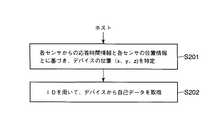
ホスト装置11は、同一デバイスIDに対応するセンサ21,22,23それぞれからの3つの応答時間が揃うと、そのデバイスIDに対応するデバイスの位置を特定するための処理を行う(ステップS201)。このステップS201では、ホスト装置11は、センサ21によって検知された応答時間Tx、センサ22によって検知された応答時間Ty、センサ23によって検知された応答時間Tzの値を、それぞれ物理的な距離の値に換算する。そして、ホスト装置11は、換算によって得られた3つの距離の値と、センサ21,22,23それぞれの配置位置とに基づいて、デバイスの位置(x,y,z)を算出する。 When the three response times from the
この後、ホスト装置11は、センサ21,22,23から受信したデバイスID毎に、そのデバイスIDで指定されるデバイスに対して形状情報取得要求を送信することにより、そのデバイスIDで指定されるデバイスから形状情報を含む自己データを取得する(ステップS202)。 Thereafter, for each device ID received from the
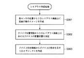
次に、図6のフローチャートを参照して、クライアント端末51によって実行されるレイアウト図自動作成処理について説明する。
ホスト装置11から各デバイス31の位置情報および形状情報を受信すると、クライアント端末51は、以下の処理を実行する。Next, the layout diagram automatic creation processing executed by the
When the position information and shape information of each
クライアント端末51は、センサ21,22,23それぞれの3次元空間上の位置から、部屋の壁のイメージを3Dレイアウト画面上に作成する(ステップS301)。3レイアウト画面は、CADソフトウェアによって提供される作図画面である。ステップS301では、図7に示すように、3次元形状の壁のイメージ100が作図される。 The
次いで、クライアント端末51は、各デバイス31の位置情報から、3Dレイアウト画面上における各デバイス31の位置を決定する(ステップS302)。そして、クライアント端末51は、各デバイス31の形状情報から、図7に示すように、各デバイスの形状を示す3Dオブジェクト101を作成し、各3Dオブジェクト101を3Dレイアウト画面上における該当する位置に配置する(ステップS303)。3Dオブジェクト101の表面の色は、形状情報で指定される色で塗られる。 Next, the
3Dレイアウト画面を見ることにより、設備管理者は、どこにどのような形状のデバイスが存在するかを容易に把握することが出来る。 By looking at the 3D layout screen, the facility manager can easily grasp where and what type of device exists.
次に、図8を参照して、互いに関連するデバイス群の中の一つのデバイスから、関連するデバイス群それぞれの自己データをまとめて取得する処理について説明する。 Next, with reference to FIG. 8, a description will be given of a process for collectively acquiring the self data of each related device group from one device among the related device groups.
一般に、多くのデバイスは互いに関連して動作する。互いに関連するデバイス同士(例えば、パーソナルコンピュータとそれに接続されたプリンタ、あるいはTVとそれに接続されたビデオレコーダ)のいずれか一方はマスタとして機能し、他方はスレーブとして機能する。図8においては、デバイス(A)31とデバイス(B)31とがUSBのようなケーブル100で接続されており、デバイス(A)31がマスタ、デバイス(B)31がスレーブとして機能する。デバイス(A)31およびデバイス(B)31は近接して配置されている。 In general, many devices operate in conjunction with each other. One of devices associated with each other (for example, a personal computer and a printer connected thereto, or a TV and a video recorder connected thereto) functions as a master, and the other functions as a slave. In FIG. 8, a device (A) 31 and a device (B) 31 are connected by a
デバイス(A)31は、デバイス(B)31に記憶されている自己データをケーブル100を介してデバイス(B)31から取得し、それをデバイス(A)31の周辺機器を示すスレーブ情報として自身の自己データに追加する。デバイス(B)31はビーコン信号に対して応答せず、デバイス(A)31だけがビーコン信号に対して応答する。デバイス(A)31のデバイスIDおよび位置のみが検知され、デバイス(B)31のデバイスIDおよび位置は検知されない。 The device (A) 31 acquires its own data stored in the device (B) 31 from the device (B) 31 via the
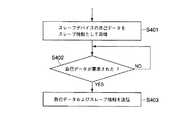
次に、図9のフローチャートを参照して、デバイス(A)31によって実行される動作について説明する。 Next, operations executed by the device (A) 31 will be described with reference to the flowchart of FIG.
デバイス(A)31は、上述したように、まず、デバイス(B)31に記憶されている自己データをケーブル100を介してデバイス(B)31から取得し、それをデバイス(A)31の周辺機器を示すスレーブ情報として自身の自己データに追加する(ステップS401)。デバイス(A)31のデバイスIDを含む形状データ取得要求(REQ)をホスト装置11から受信すると、デバイス(A)31は、自身の自己データとスレーブ情報とをホスト装置11に送信する(ステップS403)。ホスト装置11は、デバイス(A)31との通信を行うだけで、デバイス(A)31の形状のみならず、そのデバイス(A)31に近接した位置に周辺機器が存在すること、およびその周辺機器の形状を認識することが出来る。これにより、より少ない通信回数で、管理対象空間内の各デバイスの位置および形状を認識することが可能となる。 As described above, the device (A) 31 first acquires the self-data stored in the device (B) 31 from the device (B) 31 via the
また、本発明は上記実施形態そのままに限定されるものではなく、実施段階ではその要旨を逸脱しない範囲で構成要素を変形して具体化できる。また、上記実施形態に開示されている複数の構成要素の適宜な組み合わせにより、種々の発明を形成できる。例えば、実施形態に示される全構成要素から幾つかの構成要素を削除してもよい。さらに、異なる実施形態にわたる構成要素を適宜組み合わせてもよい。 Further, the present invention is not limited to the above-described embodiments as they are, and can be embodied by modifying the constituent elements without departing from the scope of the invention in the implementation stage. In addition, various inventions can be formed by appropriately combining a plurality of components disclosed in the embodiment. For example, some components may be deleted from all the components shown in the embodiment. Furthermore, constituent elements over different embodiments may be appropriately combined.
11…ホスト装置、21,22,23…センサ、31…デバイス(電子機器)、111…位置検出部、112…形状データ取得部、51…クライアント端末、312…メモリ、313…無線通信ユニット。 DESCRIPTION OF
Claims (8)
Translated fromJapanese前記第1センサ、第2センサ、および第3センサそれぞれとの通信を実行するホスト装置であって、前記第1センサ、第2センサ、および第3センサそれぞれによって検知された前記各電子機器との間の距離と、前記空間内における前記第1センサ、第2センサ、および第3センサそれぞれの位置とに基づいて、前記空間内における前記各電子機器の位置を検出する手段と、前記第1センサ、第2センサ、および第3センサそれぞれによって検知された前記各電子機器の識別子を用いて前記各電子機器との無線通信を実行することによって、前記各電子機器から当該電子機器の形状を示す形状情報を取得する手段とを含むホスト装置とを具備することを特徴とする機器管理システム。A first sensor, a second sensor, and a third sensor configured to detect a distance between each electronic device existing in the space and an identifier of each electronic device using a wireless signal;
A host device that performs communication with each of the first sensor, the second sensor, and the third sensor, and each of the electronic devices detected by the first sensor, the second sensor, and the third sensor. Means for detecting the position of each electronic device in the space based on the distance between the first sensor, the second sensor, and the third sensor in the space; and the first sensor The shape indicating the shape of the electronic device from each electronic device by performing wireless communication with each electronic device using the identifier of each electronic device detected by each of the second sensor and the third sensor A device management system comprising: a host device including means for acquiring information.
マスタとして機能する電子機器は、当該電子機器のスレーブとして機能する他の電子機器から当該他の電子機器の計情情報をスレーブ情報として取得する手段と、前記ホスト装置からの要求に応じて、前記記憶装置の形状情報と前記スレーブ情報とを前記ホスト装置に送信する手段とを含むことを特徴とする請求項4記載の機器管理システム。Each electronic device functions as one of a master and a slave,
In response to a request from the host device, the electronic device functioning as a master obtains information information of the other electronic device as slave information from another electronic device functioning as a slave of the electronic device. 5. The device management system according to claim 4, further comprising means for transmitting shape information of the storage device and the slave information to the host device.
空間内にそれぞれ分散して配置され、各々が無線信号を用いて前記空間内に存在する前記電子機器との間の距離および前記電子機器の識別子を検知するように構成された第1センサ、第2センサ、および第3センサと、
前記第1センサ、第2センサ、および第3センサそれぞれとの通信を実行するホスト装置であって、前記第1センサ、第2センサ、および第3センサそれぞれによって検知された前記電子機器との間の距離と、前記空間内における前記第1センサ、第2センサ、および第3センサそれぞれの位置とに基づいて、前記空間内における前記電子機器の位置を検出する手段と、前記第1センサ、第2センサ、および第3センサの各々によって検知された識別子を用いて前記電子機器との無線通信を実行することによって、前記電子機器から当該電子機器の形状を示す形状情報を取得する手段とを含むホスト装置とを具備することを特徴とする機器管理システム。An electronic device including a main body, a storage device storing shape information indicating the shape of the main body, and a wireless communication device that performs wireless communication with the outside;
A first sensor arranged to be dispersed in the space, each configured to detect a distance from the electronic device existing in the space and an identifier of the electronic device using a wireless signal; Two sensors and a third sensor;
A host device that performs communication with each of the first sensor, the second sensor, and the third sensor, between the electronic device detected by each of the first sensor, the second sensor, and the third sensor Based on the distance and the positions of the first sensor, the second sensor, and the third sensor in the space, a means for detecting the position of the electronic device in the space, the first sensor, Means for acquiring shape information indicating the shape of the electronic device from the electronic device by performing wireless communication with the electronic device using an identifier detected by each of the two sensors and the third sensor. A device management system comprising a host device.
Priority Applications (2)
| Application Number | Priority Date | Filing Date | Title |
|---|---|---|---|
| JP2003425036AJP2005179026A (en) | 2003-12-22 | 2003-12-22 | Equipment management system |
| US10/979,156US20050137827A1 (en) | 2003-12-22 | 2004-11-03 | System and method for managing arrangement position and shape of device |
Applications Claiming Priority (1)
| Application Number | Priority Date | Filing Date | Title |
|---|---|---|---|
| JP2003425036AJP2005179026A (en) | 2003-12-22 | 2003-12-22 | Equipment management system |
Publications (1)
| Publication Number | Publication Date |
|---|---|
| JP2005179026Atrue JP2005179026A (en) | 2005-07-07 |
Family
ID=34675415
Family Applications (1)
| Application Number | Title | Priority Date | Filing Date |
|---|---|---|---|
| JP2003425036AWithdrawnJP2005179026A (en) | 2003-12-22 | 2003-12-22 | Equipment management system |
Country Status (2)
| Country | Link |
|---|---|
| US (1) | US20050137827A1 (en) |
| JP (1) | JP2005179026A (en) |
Cited By (6)
| Publication number | Priority date | Publication date | Assignee | Title |
|---|---|---|---|---|
| JP2014065567A (en)* | 2012-09-25 | 2014-04-17 | Daifuku Co Ltd | Position measuring system and article storing facility with the same |
| JP2014194663A (en)* | 2013-03-28 | 2014-10-09 | Fujitsu Ltd | Management device, article inventory management program and article inventory management method |
| KR101857130B1 (en) | 2017-10-11 | 2018-05-11 | 엘아이지넥스원 주식회사 | System for tracing location of surveillance assets |
| KR101857131B1 (en)* | 2017-10-11 | 2018-05-11 | 엘아이지넥스원 주식회사 | Method for tracing location of surveillance assets |
| JP2019067370A (en)* | 2017-09-28 | 2019-04-25 | アップル インコーポレイテッドApple Inc. | Location-Based Credential Selection for Wireless Transactions |
| WO2025197511A1 (en)* | 2024-03-18 | 2025-09-25 | ソニーセミコンダクタソリューションズ株式会社 | Information processing device, information processing method, program, and wireless communication system |
Families Citing this family (23)
| Publication number | Priority date | Publication date | Assignee | Title |
|---|---|---|---|---|
| WO2005086802A2 (en) | 2004-03-08 | 2005-09-22 | Proxense, Llc | Linked account system using personal digital key (pdk-las) |
| US7643965B2 (en)* | 2005-08-10 | 2010-01-05 | Olympus Corporation | EMI management system and method |
| TW200723146A (en)* | 2005-09-06 | 2007-06-16 | Uchida Yoko Kk | Space providing system and information display system |
| WO2007051118A2 (en)* | 2005-10-25 | 2007-05-03 | Nxstage Medical, Inc | Safety features for medical devices requiring assistance and supervision |
| US8219129B2 (en)* | 2006-01-06 | 2012-07-10 | Proxense, Llc | Dynamic real-time tiered client access |
| US11206664B2 (en) | 2006-01-06 | 2021-12-21 | Proxense, Llc | Wireless network synchronization of cells and client devices on a network |
| US7904718B2 (en) | 2006-05-05 | 2011-03-08 | Proxense, Llc | Personal digital key differentiation for secure transactions |
| US9269221B2 (en) | 2006-11-13 | 2016-02-23 | John J. Gobbi | Configuration of interfaces for a location detection system and application |
| US8659427B2 (en) | 2007-11-09 | 2014-02-25 | Proxense, Llc | Proximity-sensor supporting multiple application services |
| WO2009102979A2 (en) | 2008-02-14 | 2009-08-20 | Proxense, Llc | Proximity-based healthcare management system with automatic access to private information |
| KR101020859B1 (en)* | 2008-08-19 | 2011-03-09 | 광주과학기술원 | A method and system for detecting distance between nodes in wireless sensor network |
| US8606903B2 (en)* | 2008-12-04 | 2013-12-10 | King Saud University | Cooperative packet routing for wireless sensor networks |
| US9418205B2 (en) | 2010-03-15 | 2016-08-16 | Proxense, Llc | Proximity-based system for automatic application or data access and item tracking |
| US8918854B1 (en) | 2010-07-15 | 2014-12-23 | Proxense, Llc | Proximity-based system for automatic application initialization |
| US20120120051A1 (en)* | 2010-11-16 | 2012-05-17 | Shu-Ming Liu | Method and system for displaying stereoscopic images |
| US8857716B1 (en) | 2011-02-21 | 2014-10-14 | Proxense, Llc | Implementation of a proximity-based system for object tracking and automatic application initialization |
| CN103253515B (en)* | 2012-02-20 | 2015-06-03 | 苏州人为峰软件科技有限公司 | Pipeline type logistics ultrasound conveying control method |
| WO2014183106A2 (en) | 2013-05-10 | 2014-11-13 | Proxense, Llc | Secure element as a digital pocket |
| KR102516354B1 (en)* | 2015-09-15 | 2023-03-31 | 삼성전자주식회사 | Method of measuring time difference between detection time, and a device operating the same |
| JP6623869B2 (en)* | 2016-03-16 | 2019-12-25 | 株式会社リコー | Device management system, device management device, program, and device management method |
| WO2018143994A1 (en) | 2017-02-02 | 2018-08-09 | Hewlett-Packard Development Company, L.P. | Three-dimensional scanning with functional elements |
| CN113642938B (en)* | 2021-10-13 | 2021-12-10 | 江苏宽程装备科技有限公司 | Intelligent production management method and system |
| CN116080108B (en)* | 2023-02-17 | 2023-07-25 | 浙江恒亿达复合材料有限公司 | Data acquisition management system for production process of wind power glass fiber pultrusion plate |
Family Cites Families (3)
| Publication number | Priority date | Publication date | Assignee | Title |
|---|---|---|---|---|
| GB9625208D0 (en)* | 1996-12-04 | 1997-01-22 | Olivetti Research Ltd | Detection system for determining information about objects |
| US6556942B1 (en)* | 2000-09-29 | 2003-04-29 | Ut-Battelle, Llc | Short range spread-spectrum radiolocation system and method |
| US7035757B2 (en)* | 2003-05-09 | 2006-04-25 | Intel Corporation | Three-dimensional position calibration of audio sensors and actuators on a distributed computing platform |
- 2003
- 2003-12-22JPJP2003425036Apatent/JP2005179026A/ennot_activeWithdrawn
- 2004
- 2004-11-03USUS10/979,156patent/US20050137827A1/ennot_activeAbandoned
Cited By (7)
| Publication number | Priority date | Publication date | Assignee | Title |
|---|---|---|---|---|
| JP2014065567A (en)* | 2012-09-25 | 2014-04-17 | Daifuku Co Ltd | Position measuring system and article storing facility with the same |
| JP2014194663A (en)* | 2013-03-28 | 2014-10-09 | Fujitsu Ltd | Management device, article inventory management program and article inventory management method |
| JP2019067370A (en)* | 2017-09-28 | 2019-04-25 | アップル インコーポレイテッドApple Inc. | Location-Based Credential Selection for Wireless Transactions |
| US10972911B2 (en) | 2017-09-28 | 2021-04-06 | Apple Inc. | Location-based credential selection for wireless transactions |
| KR101857130B1 (en) | 2017-10-11 | 2018-05-11 | 엘아이지넥스원 주식회사 | System for tracing location of surveillance assets |
| KR101857131B1 (en)* | 2017-10-11 | 2018-05-11 | 엘아이지넥스원 주식회사 | Method for tracing location of surveillance assets |
| WO2025197511A1 (en)* | 2024-03-18 | 2025-09-25 | ソニーセミコンダクタソリューションズ株式会社 | Information processing device, information processing method, program, and wireless communication system |
Also Published As
| Publication number | Publication date |
|---|---|
| US20050137827A1 (en) | 2005-06-23 |
Similar Documents
| Publication | Publication Date | Title |
|---|---|---|
| JP2005179026A (en) | Equipment management system | |
| EP3605314B1 (en) | Display method and apparatus | |
| US9781546B2 (en) | Server information handling system wireless management and topology | |
| KR101969624B1 (en) | Gesture control method, apparatus and system | |
| US9432802B2 (en) | Communication device and communication system | |
| KR102821700B1 (en) | Electronic device and method for calculating position | |
| US9807728B2 (en) | Server information handling system wireless management and topology | |
| CN105100390A (en) | Mobile terminal and method for controlling the mobile terminal | |
| JP5421762B2 (en) | Display device, control method thereof, and display system | |
| KR101898101B1 (en) | IOT interaction system | |
| KR101680667B1 (en) | Mobile device and method for controlling the mobile device | |
| US10889001B2 (en) | Service provision system | |
| US20160171353A1 (en) | Method and apparatus for generating or using interaction activity information | |
| JP2001297044A (en) | Digital information equipment network device | |
| US20180069975A1 (en) | Information display system and image forming apparatus | |
| KR101185097B1 (en) | Method for using contents with mobile terminal by using localization and system thereof | |
| US8285303B2 (en) | Area specifying apparatus, communication system, and area specifying method | |
| KR20170083328A (en) | Mobile device and method for controlling the mobile device | |
| CN116300499A (en) | Equipment control method, device, electronic equipment and storage medium | |
| CN109873958B (en) | Camera shutter control method, device and system | |
| CN108012024A (en) | The method and mobile terminal of a kind of calendar notification | |
| JP6094035B2 (en) | Image transmission apparatus, image transmission system, and program | |
| US20140237270A1 (en) | Power supply control apparatus, power supply control system and power supply control method | |
| JP2007019575A (en) | Terminal management apparatus, terminal management system, processing method in these, and program for causing computer to execute this method | |
| CN110998621A (en) | Method for real-time material and inventory management based on location information using beacons and system for performing the same |
Legal Events
| Date | Code | Title | Description |
|---|---|---|---|
| A621 | Written request for application examination | Free format text:JAPANESE INTERMEDIATE CODE: A621 Effective date:20060130 | |
| A761 | Written withdrawal of application | Free format text:JAPANESE INTERMEDIATE CODE: A761 Effective date:20061117 |