Movatterモバイル変換


[0]ホーム

URL:


JP2005177227A - Headrest of car seat - Google Patents

Headrest of car seat
Download PDF

Info

Publication number
JP2005177227A
JP2005177227AJP2003424197AJP2003424197AJP2005177227AJP 2005177227 AJP2005177227 AJP 2005177227AJP 2003424197 AJP2003424197 AJP 2003424197AJP 2003424197 AJP2003424197 AJP 2003424197AJP 2005177227 AJP2005177227 AJP 2005177227A
Authority
JP
Japan
Prior art keywords
link
headrest
arm
motor
collision
Prior art date
Legal status (The legal status is an assumption and is not a legal conclusion. Google has not performed a legal analysis and makes no representation as to the accuracy of the status listed.)
Granted
Application number
JP2003424197A
Other languages
Japanese (ja)
Other versions
JP4453901B2 (en
Inventor
Eiji Masutani
英二 増谷
Current Assignee (The listed assignees may be inaccurate. Google has not performed a legal analysis and makes no representation or warranty as to the accuracy of the list.)
TS Tech Co Ltd
Original Assignee
TS Tech Co Ltd
Priority date (The priority date is an assumption and is not a legal conclusion. Google has not performed a legal analysis and makes no representation as to the accuracy of the date listed.)
Filing date
Publication date
Application filed by TS Tech Co LtdfiledCriticalTS Tech Co Ltd
Priority to JP2003424197ApriorityCriticalpatent/JP4453901B2/en
Publication of JP2005177227ApublicationCriticalpatent/JP2005177227A/en
Application grantedgrantedCritical
Publication of JP4453901B2publicationCriticalpatent/JP4453901B2/en
Anticipated expirationlegal-statusCritical
Expired - Fee Relatedlegal-statusCriticalCurrent

Links

Images

Landscapes

Abstract

<P>PROBLEM TO BE SOLVED: To provide a headrest which solves the problem that a full effect of preventing whiplash injury by actuation after sensing a rear-end collision cannot be expected as a subtle back and forth adjustment is difficult. <P>SOLUTION: A headrest 3 is formed in an upper part of a backrest seat 2 of a car seat 1 so that it can move back and forth freely against a pillar 8 attached to a support member 9 of the backrest seat 2 with a parallel link mechanism L, the parallel link mechanism L is so structured that it can easily adjust a lengthwise position by the operation of a position adjustment link A with a motor 16, a forecasting system S which anticipates rear impact by a radar or the like provided at a desired position is installed in the car body provided with the car seat 1, an impact forecasting signal from the forecasting system S turns on electricity to the motor 16, an impact forecasting actuation link B is operated prior to the position adjustment link A and the headrest 3 is moved to the forefront position. <P>COPYRIGHT: (C)2005,JPO&NCIPI

Description

Translated fromJapanese

本発明は、車両用シートのヘッドレストに係るものであり、特に、むち打ち症対策のヘッドレストを提供するものである。  The present invention relates to a headrest for a vehicle seat, and particularly provides a headrest for preventing whiplash.

従来、背凭シートの上部に設けたヘッドレストは、該ヘッドレストのピラーを背凭シートの支持部材に装着している。
このヘッドレストのヘッドレストフレームとピラーとの間に平行リンク機構を設け、平行リンク機構によりヘッドレストは背凭シートに対して前後移動可能に構成する。平行リンク機構にはラッチとラチェットを設けて、一段ずつ前側に移動させ、一段ずつ移動させるためのヘッドレストの前側への移動は可能であるが、ヘッドレストの後側の移動は阻止して頭部を支持するようにしている。
ヘッドレストは前後位置調節操作により最前方位置まで前進すると、ラチェットを開放させ、一旦最後方位置に戻る。
一方、ヘッドレスト内には後突を感知するセンサー部を設け、センサー部が後突を感知すると、ヘッドレストを最前方位置まで強制移動させるようにした車両用シートのヘッドレストは公知である(特許文献1参照)。
特開2000−342379号公報
2. Description of the Related Art Conventionally, a headrest provided on an upper portion of a backrest seat has a pillar of the headrest attached to a support member of the backrest seat.
A parallel link mechanism is provided between the headrest frame of the headrest and the pillar, and the headrest is configured to be movable back and forth with respect to the back seat by the parallel link mechanism. The parallel link mechanism is provided with a latch and a ratchet, and it is possible to move the headrest to the front side one step at a time, but it is possible to move the headrest to the front side. I try to support it.
When the headrest is advanced to the forefront position by the front / rear position adjustment operation, the ratchet is released and temporarily returned to the rearmost position.
On the other hand, a headrest of a vehicle seat in which a sensor unit for detecting a rear collision is provided in the headrest and the headrest is forcibly moved to the foremost position when the sensor unit detects the rear collision is known (Patent Document 1). reference).
JP 2000-342379 A

前記公知例は、ラッチとラチェットによる「段」調節のため、微妙な前後調節が困難である課題がある。
また、センサー部の後突感知後のヘッドレストの移動では、既に頭部も後方移動を開始しており、むち打ち症予防の十分な効果を期待できない。
本願は、無段階のヘッドレストの位置調節をしつつ、この無段階の位置調節機構によって、予想される後突に対応させてヘッドレストを支持位置に移動させるように工夫したものである。
In the known example, there is a problem that it is difficult to make a fine back-and-forth adjustment because of the “step” adjustment by the latch and the ratchet.
Further, in the movement of the headrest after detecting the rear collision of the sensor unit, the head has already started to move backward, and a sufficient effect for preventing whiplash cannot be expected.
In the present application, while adjusting the position of the stepless headrest, the stepless position adjustment mechanism is devised so as to move the headrest to the support position in accordance with an expected rear collision.

本発明は、車両用シート1の背凭シート2の上部に該背凭シート2の支持部材9に装着するピラー8に対して平行リンク機構Lにより前後動自在にヘッドレスト3を設け、該平行リンク機構Lはモータ16により位置調節リンクAを作動させて前後位置調節自在に構成し、前記車両用シート1を設けた車体には所望位置に設けたレーダー等により後方からの衝突を事前に予測する予測システムSを搭載し、該予測システムSからの衝突予測信号によりモータ16に通電して、前記位置調節リンクAに優先させて衝突予測時作動リンクBを作動させてヘッドレスト3を最前方位置に移動するように構成した車両用シートのヘッドレストとしたものである。
本発明は、前記位置調節リンクAは、前記モータ16の出力回転軸18の一端に設けた位置調節用アーム19と、該位置調節用アーム19に取付けられ平行リンク機構Lの後側リンクアーム12aのピン23に係合する長孔22を有する調節ロッド20とを有して構成し、前記衝突予測時作動リンクBは、前記モータ16の出力回転軸18の他端に設けたワンウエイクラッチ27と、該ワンウエイクラッチ27により回動する後突作動アーム35と、該後突作動アーム35の軸37に継脱する上部フック部48を有するロックリンク45と、該ロックリンク45の下部係合部46に係合する前側係合フック43を有するドライブリンク39とを有して構成し、前記ドライブリンク39は前記前側係合フック43が前記ロックリンク45の下部係合部46に係合して前後調節時には回動停止し、予測システムSからの衝突予測信号によりモータ16に通電されると、前記後突作動アーム35の軸37との係合が外れたロックリンク45の下部係合部46がドライブリンク39の前側係合フック43から外れ、ドライブリンク39の後側係合フック部42が後側リンクアーム12aのピン23に係合して前記長孔22内を移動させるように構成した車両用シートのヘッドレストとしたものである。
本発明は、前記平行リンク機構Lは常時バネ24によりヘッドレスト3を後方移動させるように付勢され、前記ドライブリンク39は前側係合フック43が下部係合部46より外れるとピン23を前方移動させるように常時バネ50により付勢し、該バネ50は前記バネ24より弾力を強くした車両用シートのヘッドレストとしたものである。
In the present invention, aheadrest 3 is provided on the upper portion of abackrest 2 of avehicle seat 1 so as to be movable back and forth by a parallel link mechanism L with respect to apillar 8 attached to asupport member 9 of thebackrest 2. The mechanism L is configured such that the position adjustment link A is actuated by themotor 16 so that the front and rear positions can be adjusted, and the vehicle body provided with thevehicle seat 1 predicts a collision from the rear in advance by a radar or the like provided at a desired position. A prediction system S is mounted, themotor 16 is energized by a collision prediction signal from the prediction system S, the collision adjustment operation link B is operated in preference to the position adjustment link A, and theheadrest 3 is brought to the foremost position. The vehicle seat headrest is configured to move.
In the present invention, the position adjusting link A includes aposition adjusting arm 19 provided at one end of theoutput rotation shaft 18 of themotor 16 and arear link arm 12a of the parallel link mechanism L attached to theposition adjusting arm 19. And anadjustment rod 20 having along hole 22 that engages with thepin 23, and the collision prediction operation link B includes a one-way clutch 27 provided at the other end of theoutput rotation shaft 18 of themotor 16. A rear-projection operating arm 35 that is rotated by the one-way clutch 27; alock link 45 having anupper hook portion 48 that is connected to and disengaged from theshaft 37 of the rear-projection operating arm 35; and a lowerengaging portion 46 of the lock link 45 Adrive link 39 having afront engagement hook 43 that engages with thedrive link 39, and thedrive link 39 includes a lower portion of thelock link 45. When themotor 16 is energized by the collision prediction signal from the prediction system S, the lock is released from the engagement with theshaft 37 of the rear-projection operating arm 35. Thelower engagement portion 46 of thelink 45 is disengaged from thefront engagement hook 43 of thedrive link 39, and the rearengagement hook portion 42 of thedrive link 39 is engaged with thepin 23 of therear link arm 12a, so that thelong hole 22 is engaged. The vehicle seat headrest is configured to move inside.
In the present invention, the parallel link mechanism L is always urged by thespring 24 to move theheadrest 3 backward, and thedrive link 39 moves thepin 23 forward when thefront engagement hook 43 is disengaged from thelower engagement portion 46. Thespring 50 is always urged by aspring 50, and thespring 50 is a headrest of a vehicle seat that is more elastic than thespring 24.

請求項1の発明では、モータ16による無段階のヘッドレスト3の位置調節にして操作性を向上させると共に、モータ16によって予想される後突に対応させてヘッドレスト3を支持位置に移動させることができ、むち打ち症予防の十分な効果が高く、また、モータ16を含めて機構部をヘッドレスト3内に設けられ、車両用シート1側の対応を最小限にできる。
また、一個のモータ16により全ての操作(作動)を可能にでき、コストを低くできる。
請求項2の発明では、位置調節リンクAと衝突予測時作動リンクBにより構成しているので、簡単な構成でモータ16を含めて機構部を小型にしてヘッドレスト3内に設けられる。
According to the first aspect of the invention, the operability is improved by adjusting the position of theheadrest 3 steplessly by themotor 16 and theheadrest 3 can be moved to the support position in response to the rear collision expected by themotor 16. In addition, the effect of preventing whiplash is sufficiently high, and the mechanism portion including themotor 16 is provided in theheadrest 3, so that the correspondence on thevehicle seat 1 side can be minimized.
In addition, all operations (operations) can be performed by onemotor 16, and the cost can be reduced.
According to the second aspect of the present invention, since the position adjusting link A and the collision predicting operation link B are used, the mechanism including themotor 16 can be reduced in size and provided in theheadrest 3 with a simple configuration.

本発明の実施例を図面により説明すると、1は車両用シート、2は車両用シート1の背凭シート、3は背凭シート2の上部に設けたヘッドレストである。
ヘッドレスト3は、ヘッドレストフレーム4にクッション材5を設けて構成する。実施例のヘッドレスト3はクッション材5の周囲を表皮部材6で被覆しているが表皮部材6は要件ではない。
8はヘッドレスト3を背凭シート2の支持部9に装着するピラーであり、実施例では左右一対の脚部10を所定間隔を置いて設けているが、平板形状に形成してもよい。
また、背凭シート2の支持部材9には公知の構成の脚部10に設けた係合部に係合する係合体を設け、ピラー8を上下所定位置にて保持するようにして、ヘッドレスト3の高さ調節を行えるようにすると、ヘッドレスト3の位置を着座者の体格に合わせられて、好適である。
An embodiment of the present invention will be described with reference to the drawings.Reference numeral 1 denotes a vehicle seat, 2 denotes a backrest seat of thevehicle seat 1, and 3 denotes a headrest provided on an upper portion of thebackrest seat 2.
Theheadrest 3 is configured by providing acushion material 5 on aheadrest frame 4. Theheadrest 3 of the embodiment covers the periphery of thecushion material 5 with the skin member 6, but the skin member 6 is not a requirement.
Reference numeral 8 denotes a pillar for mounting theheadrest 3 to thesupport portion 9 of thedorsal seat 2, and in the embodiment, a pair of left andright leg portions 10 are provided at a predetermined interval, but may be formed in a flat plate shape.
Further, thesupport member 9 of thedorsal seat 2 is provided with an engagement body that engages with an engagement portion provided on aleg portion 10 of a known configuration, so that thepillar 8 is held at a predetermined position in the vertical direction. If the height of theheadrest 3 can be adjusted, the position of theheadrest 3 can be adjusted to the physique of the seated person, which is preferable.

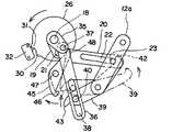
しかして、前記ヘッドレストフレーム4は、平行リンク機構Lにより前記ピラー8に前後動自在に取付ける。ピラー8には固定部材11を設け、固定部材11には前後一対のリンクアーム12の下部を軸13により回動自在に取付ける。各リンクアーム12の上部は連動部材14(ヘッドレストフレーム4)に軸15により回動自在に取付ける。
前記固定部材11には、モータ16を取付け、モータ16の出力回転軸18の一端には位置調節用アーム19の基部を取付け、位置調節用アーム19には調節ロッド20の一端を軸21により取付ける。調節ロッド20の他端には長孔22を形成し、長孔22には前記後側リンクアーム12aのピン23を係合させる。
モータ16は位置調節用アーム19を正逆何れかの方向に回転させて、位置調節用アーム19の長孔22の先端側に係合しているピン23を押し引きし、後側後側リンクアーム12aのピン23を軸13中心に前後回動させ、ピン23の前後回動によりヘッドレストフレーム4をピラー8に対して前後移動させる。
したがって、位置調節用アーム19と調節ロッド20とにより位置調節リンクAを構成する。
Thus, theheadrest frame 4 is attached to thepillar 8 by the parallel link mechanism L so as to be movable back and forth. A fixing member 11 is provided on thepillar 8, and a lower portion of a pair of front andrear link arms 12 is attached to the fixing member 11 so as to be rotatable by ashaft 13. The upper part of eachlink arm 12 is rotatably attached to the interlocking member 14 (headrest frame 4) by ashaft 15.
Amotor 16 is attached to the fixing member 11, a base of aposition adjusting arm 19 is attached to one end of anoutput rotating shaft 18 of themotor 16, and one end of an adjustingrod 20 is attached to theposition adjusting arm 19 by ashaft 21. . Along hole 22 is formed at the other end of the adjustingrod 20, and thepin 23 of therear link arm 12 a is engaged with thelong hole 22.
Themotor 16 rotates theposition adjusting arm 19 in either the forward or reverse direction, and pushes and pulls thepin 23 engaged with the distal end side of thelong hole 22 of theposition adjusting arm 19, and the rear rear link. Thepin 23 of thearm 12a is rotated back and forth about theshaft 13, and theheadrest frame 4 is moved back and forth with respect to thepillar 8 by rotating thepin 23 back and forth.
Therefore, the position adjusting link A is constituted by theposition adjusting arm 19 and the adjustingrod 20.

24はリンクアーム12を常時後方回動するように付勢するバネであり、一端をリンクアーム12に係止し、他端は図示は省略するが、固定部材11に係止する。
前記モータ16の出力回転軸18の他端にはロータ26をワンウエイクラッチ27を介して正逆何れか一方向に回転するように取付ける。ロータ26の外周には突起30、31を設け、突起30、31の移動路にはスイッチ32を設ける。
前記出力回転軸18の他端にはワンウエイクラッチ27を介して後突作動アーム35の基部を取付ける(なお、理解を容易にするため、後突作動アーム35は側面図で位置調節用アーム19と一緒に記載している。)。後突作動アーム35の先端には後突作動ロッド36の一端を軸37により取付ける。後突作動ロッド36の他端には長孔38を形成し、長孔38にはドライブリンク39の一端に設けたピン40を係合させる。ドライブリンク39は、その前後中間部を固定部材11に軸13により回動自在に取付ける。ドライブリンク39は後端には後側係合フック部42を設ける。後側係合フック部42はドライブリンク39が軸13中心に回動すると、ピン23に当接するように配置する。
Reference numeral 24 denotes a spring that urges thelink arm 12 to always rotate backward, and one end is locked to thelink arm 12, and the other end is locked to the fixing member 11 although not shown.
Arotor 26 is attached to the other end of theoutput rotating shaft 18 of themotor 16 via a one-way clutch 27 so as to rotate in either the forward or reverse direction.Protrusions 30 and 31 are provided on the outer periphery of therotor 26, and aswitch 32 is provided on the movement path of theprotrusions 30 and 31.
The other end of theoutput rotating shaft 18 is attached with a base portion of a rearimpact operating arm 35 via a one-way clutch 27 (for the sake of easy understanding, the rearimpact operating arm 35 is connected to theposition adjusting arm 19 in a side view). It is listed together.) One end of a rear-projection operating rod 36 is attached to the tip of the rear-projection operating arm 35 by ashaft 37. Along hole 38 is formed at the other end of the rearimpact operating rod 36, and apin 40 provided at one end of thedrive link 39 is engaged with thelong hole 38. Thedrive link 39 is pivotally attached to the fixed member 11 by ashaft 13 at the front and rear intermediate portions. Thedrive link 39 is provided with a rearengagement hook portion 42 at the rear end. The rearengagement hook portion 42 is disposed so as to contact thepin 23 when thedrive link 39 rotates about theshaft 13.

ドライブリンク39の前端には前側係合フック43を設ける。前側係合フック43はロックリンク45の下部係合部46に継脱するようにする。ロックリンク45の上下中間部は軸47により固定部材11に取付け、ロックリンク45の上部には上部フック部48を形成し、上部フック部48は軸37に係合するように構成する。
この場合、ロックリンク45の下部係合部46とドライブリンク39の前側係合フック43の夫々には案内面46aと案内面43aの夫々を形成し、ドライブリンク39の前側係合フック43が下部係合部46に係合するのを案内誘導する。
また、ロックリンク45には、ドライブリンク39の前側係合フック43に係合する方向に常時回動するように付勢するバネ49を設ける。バネ49は一端をロックリンク45に係止し、他端は図示は省略するが、固定部材11に係止する。
Afront engagement hook 43 is provided at the front end of thedrive link 39. Thefront engagement hook 43 is connected to and detached from thelower engagement portion 46 of thelock link 45. The upper and lower intermediate portions of thelock link 45 are attached to the fixing member 11 by ashaft 47, and anupper hook portion 48 is formed on the upper portion of thelock link 45, and theupper hook portion 48 is configured to engage with theshaft 37.
In this case, thelower engagement portion 46 of thelock link 45 and thefront engagement hook 43 of thedrive link 39 are respectively formed with a guide surface 46a and a guide surface 43a, and thefront engagement hook 43 of thedrive link 39 is lower. It is guided to engage with theengaging portion 46.
Further, thelock link 45 is provided with aspring 49 that urges thelock link 45 so as to always rotate in a direction in which thelock link 45 is engaged with thefront engagement hook 43 of thedrive link 39. One end of thespring 49 engages with thelock link 45, and the other end engages with the fixing member 11 although not shown.

また、ロックリンク45の回動路には、ドライブリンク39の前側係合フック43が離脱したときに所定位置に待機させるためのストッパ50を設ける。
51は前記ドライブリンク39の後側係合フック部42が後側リンクアーム12aのピン23に当接するように付勢するバネであり、バネ51の弾力はバネ24の弾力より強く設定し、バネ51はバネ24の弾力に抗して平行リンク機構Lを介してヘッドレスト3を前方移動させる。
このように、後突作動アーム35とドライブリンク39とロックリンク45とにより衝突予測時作動リンクBを構成する。
In addition, astopper 50 is provided on the rotation path of thelock link 45 for waiting at a predetermined position when the front engagement hook 43 of thedrive link 39 is released.
Reference numeral 51 denotes a spring that biases the rearengagement hook portion 42 of thedrive link 39 so as to contact thepin 23 of therear link arm 12a. The elasticity of thespring 51 is set to be stronger than the elasticity of thespring 24. 51 moves theheadrest 3 forward through the parallel link mechanism L against the elasticity of thespring 24.
As described above, the collision prediction operation link B is configured by the rearcollision operation arm 35, thedrive link 39, and thelock link 45.

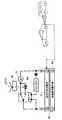
しかして、車体所望位置にはレーダー等により後方からの衝突を事前に予測する予測システムSを設け、予測システムSからの衝突予測信号によりモータ16に通電するように構成する。
実施例では、ヘッドレスト3のピラー8にモータ16に一端を接続した接続コード55の他端に設けた接続端子56を設け、背凭シート2の支持部9に前記接続端子56が接続する接続端子57を設け、接続端子57には前記接続コード58を接続し、接続コード58から接続端子56および接続端子57を介してモータ16に通電するように構成し、モータ16への通電は前後調節スイッチ59および予測システムSからの衝突予測信号により行われるように構成している。
また、予測システムSが作動して、ヘッドレスト3を後突予知作動によって前方移動させると、一旦、通電を切り、タイマー60により所定時間経過後、自動的に通電するように構成する。
Accordingly, a prediction system S that predicts a collision from behind by a radar or the like in advance is provided at a desired body position, and themotor 16 is energized by a collision prediction signal from the prediction system S.
In the embodiment, theconnection terminal 56 provided at the other end of theconnection cord 55 having one end connected to themotor 16 is provided in thepillar 8 of theheadrest 3, and theconnection terminal 56 is connected to thesupport portion 9 of thebackrest seat 2. 57, and theconnection cord 58 is connected to theconnection terminal 57, and themotor 16 is energized from theconnection cord 58 via theconnection terminal 56 and theconnection terminal 57. 59 and the collision prediction signal from the prediction system S.
Further, when the prediction system S is activated and the
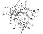
headrest 3 is moved forward by the rear collision prediction operation, the energization is once turned off, and thetimer 60 is configured to energize automatically after a predetermined time has elapsed.

次に実施例の作用を述べる。
(前後調節モード)
図3は、ヘッドレスト3が最も後方に位置しており、後側リンクアーム12aは、調節ロッド20の長孔22の後端に位置している。
この状態で、モータ16に通電すると、図3において、出力回転軸18が回転し、出力回転軸18の一端に固定の位置調節用アーム19は時計回転方向に回動する(出力回転軸18の他端側のロータ26はワンウエイクラッチ27により図において時計方向の回転は伝達されず、位置調節用アーム19が回動している間、後突作動アーム35は位置不動で停止している。)。
Next, the operation of the embodiment will be described.
(Front / back adjustment mode)
In FIG. 3, theheadrest 3 is located at the rearmost position, and therear link arm 12 a is located at the rear end of thelong hole 22 of theadjustment rod 20.
When themotor 16 is energized in this state, theoutput rotating shaft 18 rotates in FIG. 3, and theposition adjusting arm 19 fixed to one end of theoutput rotating shaft 18 rotates in the clockwise direction (theoutput rotating shaft 18 Therotor 26 on the other end side is not transmitted clockwise in the drawing by the one-way clutch 27, and therear impact arm 35 is stopped while theposition adjusting arm 19 is rotating while theposition adjusting arm 19 is rotating. .

位置調節用アーム19が回動すると調節ロッド20を牽引し、調節ロッド20の長孔22の後端内周がピン23を牽引して後側リンクアーム12aを軸13中心に前方回動させ(図4)、ヘッドレスト3を前側に移動させる。
更に、モータ16により位置調節用アーム19を回動させると、ヘッドレスト3が最前方位置に位置し、このとき、位置調節用アーム19は調節ロッド20を最大に牽引する最大牽引位置に位置する(図5)。
この状態から更に、モータ16により位置調節用アーム19を回動させると、位置調節用アーム19が調節ロッド20の最大牽引位置を通過し、調節ロッド20を戻すように作用する。
When theposition adjustment arm 19 rotates, theadjustment rod 20 is pulled, and the inner periphery of the rear end of thelong hole 22 of theadjustment rod 20 pulls thepin 23 to rotate therear link arm 12a forward about the shaft 13 ( 4), theheadrest 3 is moved to the front side.
Further, when theposition adjusting arm 19 is rotated by themotor 16, theheadrest 3 is positioned at the foremost position. At this time, theposition adjusting arm 19 is positioned at the maximum traction position where theadjustment rod 20 is pulled to the maximum ( FIG. 5).
When theposition adjusting arm 19 is further rotated by themotor 16 from this state, theposition adjusting arm 19 passes through the maximum pulling position of the adjustingrod 20 and acts to return the adjustingrod 20.

このとき、後側リンクアーム12aはバネ24により常時後方回動するように付勢され、ピン23は調節ロッド20の長孔22の後端に押し付けられているから、位置調節用アーム19が調節ロッド20を後側移動させ、調節ロッド20の長孔22が後側に移動すると、長孔22の後端にあるピン23は後方移動が許容されて調節ロッド20と共に後方移動し、後側リンクアーム12aは後側回動し、ヘッドレスト3は後側に移動する。
このように、前後調節するときの位置調節用アーム19は常時時計回転し、調節ロッド20は前後に往復移動し、ピン23は調節ロッド20の長孔22の後端内周に当接したまま前後移動させ、ヘッドレスト3はモータ16の回転力により前側に移動し、バネ24の弾力で後側に移動し、その結果、ヘッドレスト3は前後往復移動して途中の所望位置のときモータ16の通電を切ると、前後位置調節操作が終了する。
At this time, therear link arm 12a is urged so as to always rotate backward by thespring 24, and thepin 23 is pressed against the rear end of thelong hole 22 of the adjustingrod 20, so that theposition adjusting arm 19 is adjusted. When therod 20 is moved rearward and theelongated hole 22 of the adjustingrod 20 moves rearward, thepin 23 at the rear end of theelongated hole 22 is allowed to move backward and moves backward together with the adjustingrod 20, and the rear link. Thearm 12a rotates rearward, and theheadrest 3 moves rearward.
In this way, theposition adjusting arm 19 for the back and forth adjustment always rotates clockwise, theadjustment rod 20 reciprocates back and forth, and thepin 23 remains in contact with the inner periphery of the rear end of thelong hole 22 of theadjustment rod 20. Theheadrest 3 is moved forward and backward by the rotational force of themotor 16 and moved rearward by the elasticity of thespring 24. As a result, theheadrest 3 is reciprocated back and forth to energize themotor 16 when it is at a desired position in the middle. When is turned off, the front / rear position adjustment operation ends.

この前後調節モードでは、出力回転軸18は時計方向に回転し、このときワンウエイクラッチ27は切りになってロータ26と後突作動アーム35を回転させない。  In this front / rear adjustment mode, theoutput rotary shaft 18 rotates in the clockwise direction, and at this time, the one-way clutch 27 is disengaged and therotor 26 and the rearcollision operating arm 35 are not rotated.

(後突予知作動モード)
車体所望位置に設けたレーダー等により後方からの衝突を事前に予測する予測システムからの衝突予測信号がモータ16に送られ、モータ16は出力回転軸18を図6において反時計回転させる。
出力回転軸18の回転はワンウエイクラッチ27を介して後突作動アーム35に伝達され、後突作動アーム35は反時計方向に回動し、後突作動アーム35の軸37が反時計方向に回動し、軸37はロックリンク45の上部フック部48との係合を外ずすように、ロックリンク45を時計回転方向に軸47中心に回動させる。
(Rear collision prediction operation mode)
A collision prediction signal from a prediction system that predicts a collision from the rear in advance by a radar or the like provided at a desired position of the vehicle body is sent to themotor 16, and themotor 16 rotates theoutput rotary shaft 18 counterclockwise in FIG.
The rotation of theoutput rotating shaft 18 is transmitted to the rearimpact operating arm 35 via the one-way clutch 27, the rearimpact operating arm 35 rotates counterclockwise, and theshaft 37 of the rearimpact operating arm 35 rotates counterclockwise. Theshaft 37 rotates thelock link 45 about theshaft 47 in the clockwise direction so that the engagement with theupper hook portion 48 of thelock link 45 is released.

ロックリンク45が時計回転方向に軸47中心に回動すると、ロックリンク45の下部係合部46はドライブリンク39の前側係合フック43から離れ、ドライブリンク39の前側係合フック43がロックリンク45の下部係合部46から外れると、ドライブリンク39はバネ51の弾力で急激に軸13中心に時計回転方向に回転し(図7)、ドライブリンク39の後側係合フック部42が後側リンクアーム12aのピン23に当たって後側リンクアーム12aを前方回動させる(図8)。
そのため、後側リンクアーム12aの前方回動によりヘッドレスト3を前側に移動させる。
この場合、ピン23は調節ロッド20の長孔22内を前方移動するので、瞬時に後側リンクアーム12aは前方回動する。
一方、ワンウエイクラッチ27を介して出力回転軸18の回転がロータ26に伝達され、スイッチ32に接触しているロータ26の突起30が離れ、ロックリンク45の下部係合部46からドライブリンク39の前側係合フック43が外れて、ドライブリンク39が後側リンクアーム12aを前方回動させると、31がスイッチ32に接触して、モータ16を停止させる。
When thelock link 45 rotates about theshaft 47 in the clockwise direction, thelower engagement portion 46 of thelock link 45 is separated from thefront engagement hook 43 of thedrive link 39, and thefront engagement hook 43 of thedrive link 39 is locked. When thedrive link 39 is disengaged from thelower engagement portion 46 of 45, thedrive link 39 suddenly rotates clockwise around theshaft 13 due to the elasticity of the spring 51 (FIG. 7), and the rearengagement hook portion 42 of thedrive link 39 moves to the rear. Therear link arm 12a is rotated forward by hitting thepin 23 of theside link arm 12a (FIG. 8).
Therefore, theheadrest 3 is moved forward by the forward rotation of therear link arm 12a.
In this case, since thepin 23 moves forward in thelong hole 22 of the adjustingrod 20, therear link arm 12a instantaneously rotates forward.
On the other hand, the rotation of theoutput rotating shaft 18 is transmitted to therotor 26 via the one-way clutch 27, and theprotrusion 30 of therotor 26 that is in contact with theswitch 32 is separated, so that thedrive link 39 is disengaged from the lower engagingportion 46 of thelock link 45. When thefront engagement hook 43 is released and thedrive link 39 rotates therear link arm 12a forward, 31 contacts theswitch 32 and stops themotor 16.

(復帰作動モード)
後突予知作動モードにおいて、モータ16が作動してヘッドレスト3が緊急前側移動すると、ロータ26の突起31がスイッチ32に接触し、モータ16の通電を切り、その後、タイマータイマー60により所定時間経過すると自動的にモータ16に通電し、ロータ26および後突作動アーム35は反時計方向に回転する。
後突作動アーム35は軸37を反時計方向に回転させ、軸37は後突作動ロッド36を上方に牽引し、後突作動ロッド36の長孔38に係合しているドライブリンク39のピン40を上方に引き上げる。
(Return operation mode)
In the rear impact prediction operation mode, when themotor 16 is operated and theheadrest 3 is moved to the front side of the emergency, theprotrusion 31 of therotor 26 contacts theswitch 32 and themotor 16 is deenergized. Themotor 16 is automatically energized, and therotor 26 and therear impact arm 35 rotate counterclockwise.
The rear-projection operating arm 35 rotates theshaft 37 counterclockwise, and theshaft 37 pulls the rear-projection operating rod 36 upward and engages with thelong hole 38 of the rear-projection operating rod 36. Pull 40 upward.

その結果、ドライブリンク39は軸13中心に時計回転し、ドライブリンク39の前側係合フック43の案内面43aがロックリンク45の下部係合部46の案内面46aに当接してロックリンク45を時計回転させて退避し、前側係合フック43の案内面43aがロックリンク45の下部係合部46の案内面46aを通過すると、前側係合フック43がロックリンク45の下部係合部46に係合する。
また、ドライブリンク39の前側係合フック43がロックリンク45の下部係合部46に係合すると、ドライブリンク39の後側係合フック部42は後側リンクアーム12aのピン23より退避し、そのまま、位置調節用アーム19の反時計方向の回動により調節ロッド20は元の位置に戻り、後側リンクアーム12aのピン23も長孔22の後側に移動する。
そして、位置調節用アーム19および調節ロッド20が初期位置に復帰すると、後突作動アーム35の軸37はロックリンク45の上部フック部48に当接する。
この状態で、ロータ26の突起30がスイッチ32に当接してモータ16への通電を切る。
As a result, thedrive link 39 rotates clockwise around theshaft 13, and the guide surface 43 a of the frontside engagement hook 43 of thedrive link 39 abuts on the guide surface 46 a of thelower engagement portion 46 of thelock link 45, causing thelock link 45 to move. When the guide surface 43 a of thefront engagement hook 43 passes through the guide surface 46 a of thelower engagement portion 46 of thelock link 45, thefront engagement hook 43 moves to thelower engagement portion 46 of thelock link 45. Engage.
When thefront engagement hook 43 of thedrive link 39 is engaged with thelower engagement portion 46 of thelock link 45, the rearengagement hook portion 42 of thedrive link 39 is retracted from thepin 23 of therear link arm 12a, As it is, theadjustment rod 20 returns to the original position by the counterclockwise rotation of theposition adjusting arm 19, and thepin 23 of therear link arm 12 a is also moved to the rear side of thelong hole 22.
Then, when theposition adjusting arm 19 and the adjustingrod 20 return to the initial positions, theshaft 37 of the rearimpact operating arm 35 contacts theupper hook portion 48 of thelock link 45.
In this state, theprotrusion 30 of therotor 26 contacts theswitch 32 and themotor 16 is deenergized.

背凭シートおよびヘッドレストの側面図。The side view of a back seat and a headrest.ヘッドレスト内のリンク機構の斜視図。The perspective view of the link mechanism in a headrest.同側面図。The same side view.ヘッドレストを前後中間位置へ移動させた状態のリンク機構の側面図。The side view of the link mechanism of the state which moved the headrest to the front-back intermediate position.ヘッドレストを最前方位置へ移動させた状態のリンク機構の側面図。The side view of the link mechanism of the state which moved the headrest to the foremost position.後突予測信号によりモーターに通電した状態のリンク機構の側面図。The side view of the link mechanism in the state which energized the motor by the rear collision prediction signal.同ドライブリンク回動開始状態の側面図。The side view of the drive link rotation start state.同ドライブリンクによるヘッドレストを最前方位置へ移動させた状態のリンク機構の側面図。The side view of the link mechanism of the state which moved the headrest by the drive link to the foremost position.同ドライブリンクを元への復帰開始状態の側面図。The side view of the return start state based on the drive link.同ドライブリンクの復帰状態の側面図。The side view of the return state of the drive link.ロックリンクおよびドライブリンクの復帰状態の側面図。The side view of the reset state of a lock link and a drive link.ブロック図。Block Diagram.

符号の説明Explanation of symbols

1…車両用シート、2…背凭シート、3…ヘッドレスト、4…ヘッドレストフレーム、5…クッション材、6…表皮部材、8…ピラー、9…支持部材、11…固定部材、12…リンクアーム、12a…後側リンクアーム、13…軸、14…連動部材、15…軸、16…モータ、18…出力回転軸、19…位置調節用アーム、20…調節ロッド、21…軸、22…長孔、23…ピン、24…バネ、26…ロータ、27…ワンウエイクラッチ、30…突起、31…突起、32…スイッチ、35…後突作動アーム、36…後突作動ロッド、37…軸、38…長孔、39…ドライブリンク、40…ピン、42…後側係合フック部、43…前側係合フック、45…ロックリンク、46…下部係合部、47…軸、48…上部フック部、49…バネ、50…ストッパ、51…バネ、55…接続コード、56…接続端子、57…接続端子、58…接続コード、59…前後調節スイッチ、60…タイマー。  DESCRIPTION OFSYMBOLS 1 ... Vehicle seat, 2 ... Backrest seat, 3 ... Headrest, 4 ... Headrest frame, 5 ... Cushion material, 6 ... Skin member, 8 ... Pillar, 9 ... Support member, 11 ... Fixing member, 12 ... Link arm, 12a ... rear side link arm, 13 ... shaft, 14 ... interlocking member, 15 ... shaft, 16 ... motor, 18 ... output rotating shaft, 19 ... position adjusting arm, 20 ... adjusting rod, 21 ... shaft, 22 ... long hole , 23 ... pin, 24 ... spring, 26 ... rotor, 27 ... one-way clutch, 30 ... protrusion, 31 ... protrusion, 32 ... switch, 35 ... rear operation arm, 36 ... rear operation rod, 37 ... shaft, 38 ... Long hole, 39 ... Drive link, 40 ... Pin, 42 ... Rear side engagement hook part, 43 ... Front side engagement hook, 45 ... Lock link, 46 ... Lower engagement part, 47 ... Shaft, 48 ... Upper hook part, 49 ... Spring, 50 ... Stopper, 51 ... spring, 55 ... connection cord, 56 ... connection terminal, 57 ... connection terminal, 58 ... connection cord, 59 ... longitudinal adjustment switch, 60 ... timer.

Claims (3)

Translated fromJapanese
車両用シート1の背凭シート2の上部に該背凭シート2の支持部材9に装着するピラー8に対して平行リンク機構Lにより前後動自在にヘッドレスト3を設け、該平行リンク機構Lはモータ16により位置調節リンクAを作動させて前後位置調節自在に構成し、前記車両用シート1を設けた車体には所望位置に設けたレーダー等により後方からの衝突を事前に予測する予測システムSを搭載し、該予測システムSからの衝突予測信号によりモータ16に通電して、前記位置調節リンクAに優先させて衝突予測時作動リンクBを作動させてヘッドレスト3を最前方位置に移動するように構成した車両用シートのヘッドレスト。A headrest 3 is provided on the upper part of the backrest 2 of the vehicle seat 1 so as to be movable back and forth by a parallel link mechanism L with respect to a pillar 8 attached to the support member 9 of the backrest 2. The parallel link mechanism L is a motor. 16 is configured so that the position adjustment link A is actuated to adjust the front-rear position, and the vehicle body provided with the vehicle seat 1 is provided with a prediction system S that predicts a collision from the rear in advance by a radar or the like provided at a desired position. It is mounted, and the motor 16 is energized by the collision prediction signal from the prediction system S, and the headrest 3 is moved to the foremost position by operating the collision prediction operation link B in preference to the position adjustment link A. Constructed vehicle seat headrest.請求項1において、前記位置調節リンクAは、前記モータ16の出力回転軸18の一端に設けた位置調節用アーム19と、該位置調節用アーム19に取付けられ平行リンク機構Lの後側リンクアーム12aのピン23に係合する長孔22を有する調節ロッド20とを有して構成し、前記衝突予測時作動リンクBは、前記モータ16の出力回転軸18の他端に設けたワンウエイクラッチ27と、該ワンウエイクラッチ27により回動する後突作動アーム35と、該後突作動アーム35の軸37に継脱する上部フック部48を有するロックリンク45と、該ロックリンク45の下部係合部46に係合する前側係合フック43を有するドライブリンク39とを有して構成し、前記ドライブリンク39は前記前側係合フック43が前記ロックリンク45の下部係合部46に係合して前後調節時には回動停止し、予測システムSからの衝突予測信号によりモータ16に通電されると、前記後突作動アーム35の軸37との係合が外れたロックリンク45の下部係合部46がドライブリンク39の前側係合フック43から外れ、ドライブリンク39の後側係合フック部42が後側リンクアーム12aのピン23に係合して前記長孔22内を移動させるように構成した車両用シートのヘッドレスト。2. The position adjustment link A according to claim 1, wherein the position adjustment link A includes a position adjustment arm 19 provided at one end of the output rotation shaft 18 of the motor 16, and a rear link arm of the parallel link mechanism L attached to the position adjustment arm 19. And an adjustment rod 20 having a long hole 22 that engages with a pin 23 of 12a, and the collision-predicting operation link B is a one-way clutch 27 provided at the other end of the output rotating shaft 18 of the motor 16. A rear-projection operating arm 35 that is rotated by the one-way clutch 27, a lock link 45 having an upper hook portion 48 that is connected to and disengaged from the shaft 37 of the rear-projection operating arm 35, and a lower engaging portion of the lock link 45 46 and a drive link 39 having a front engagement hook 43 that engages with the drive link 39, and the drive link 39 is connected to the lock link 4. When the motor 16 is energized by the collision prediction signal from the prediction system S, the engagement with the shaft 37 of the rear collision operating arm 35 is engaged. The lower engaging portion 46 of the disengaged lock link 45 is disengaged from the front engaging hook 43 of the drive link 39, and the rear engaging hook portion 42 of the drive link 39 is engaged with the pin 23 of the rear link arm 12a. A vehicle seat headrest configured to move in the long hole 22.請求項2において、前記平行リンク機構Lは常時バネ24によりヘッドレスト3を後方移動させるように付勢され、前記ドライブリンク39は前側係合フック43が下部係合部46より外れるとピン23を前方移動させるように常時バネ50により付勢し、該バネ50は前記バネ24より弾力を強くした車両用シートのヘッドレスト。In claim 2, the parallel link mechanism L is always urged by the spring 24 to move the headrest 3 backward, and the drive link 39 moves the pin 23 forward when the front engagement hook 43 is disengaged from the lower engagement portion 46. A vehicle seat headrest that is always urged by a spring 50 so as to be moved, and the spring 50 is more elastic than the spring 24.
JP2003424197A2003-12-222003-12-22 Vehicle seat headrestExpired - Fee RelatedJP4453901B2 (en)

Priority Applications (1)

Application NumberPriority DateFiling DateTitle
JP2003424197AJP4453901B2 (en)2003-12-222003-12-22 Vehicle seat headrest

Applications Claiming Priority (1)

Application NumberPriority DateFiling DateTitle
JP2003424197AJP4453901B2 (en)2003-12-222003-12-22 Vehicle seat headrest

Related Child Applications (1)

Application NumberTitlePriority DateFiling Date
JP2009164521ADivisionJP5164274B2 (en)2009-07-132009-07-13 Vehicle seat

Publications (2)

Publication NumberPublication Date
JP2005177227Atrue JP2005177227A (en)2005-07-07
JP4453901B2 JP4453901B2 (en)2010-04-21

Family

ID=34784463

Family Applications (1)

Application NumberTitlePriority DateFiling Date
JP2003424197AExpired - Fee RelatedJP4453901B2 (en)2003-12-222003-12-22 Vehicle seat headrest

Country Status (1)

CountryLink
JP (1)JP4453901B2 (en)

Cited By (10)

* Cited by examiner, † Cited by third party
Publication numberPriority datePublication dateAssigneeTitle
JP2007055500A (en)*2005-08-252007-03-08Aisin Seiki Co Ltd Vehicle headrest device
JP2007153066A (en)*2005-12-022007-06-21Toyota Boshoku CorpMethod and device for controlling movement of vehicular seat headrest
JP2007331576A (en)*2006-06-152007-12-27Toyota Boshoku CorpHeadrest for vehicle seat
US7517015B2 (en)2005-10-172009-04-14Aisin Seiki Kabushiki KaishaHeadrest device
US7614690B2 (en)2006-08-232009-11-10Toyota Jidosha Kabushiki KaishaHeadrest control apparatus and method
WO2010084911A1 (en)2009-01-212010-07-29テイ・エス テック株式会社Vehicle seat
WO2012050656A3 (en)*2010-10-122012-08-02La-Z-Boy IncorporatedFurniture member powered headrest rotation and release system
JP2015507576A (en)*2012-01-052015-03-12ビーイー・エアロスペース・インコーポレーテッド Adjustable headrest for aircraft seat
JP5902847B1 (en)*2015-05-142016-04-13備前発条株式会社 Headrest
CN105559415A (en)*2016-02-022016-05-11锐迈机械科技(吴江)有限公司Independent headrest device

Cited By (17)

* Cited by examiner, † Cited by third party
Publication numberPriority datePublication dateAssigneeTitle
JP2007055500A (en)*2005-08-252007-03-08Aisin Seiki Co Ltd Vehicle headrest device
US7517015B2 (en)2005-10-172009-04-14Aisin Seiki Kabushiki KaishaHeadrest device
JP2007153066A (en)*2005-12-022007-06-21Toyota Boshoku CorpMethod and device for controlling movement of vehicular seat headrest
JP2007331576A (en)*2006-06-152007-12-27Toyota Boshoku CorpHeadrest for vehicle seat
US7614690B2 (en)2006-08-232009-11-10Toyota Jidosha Kabushiki KaishaHeadrest control apparatus and method
WO2010084911A1 (en)2009-01-212010-07-29テイ・エス テック株式会社Vehicle seat
US8708409B2 (en)2009-01-212014-04-29Ts Tech Co., Ltd.Vehicle seat
US8702173B2 (en)2010-10-122014-04-22La-Z-Boy IncorporatedFurniture member powered headrest rotation and release system
CN103228182A (en)*2010-10-122013-07-31La-Z-博伊有限公司 Power-driven headrest rotation and release system for furniture components
WO2012050656A3 (en)*2010-10-122012-08-02La-Z-Boy IncorporatedFurniture member powered headrest rotation and release system
CN103228182B (en)*2010-10-122016-08-10拉兹男孩联合公司 Power-driven headrest rotation and release system for furniture components
AU2011314346B2 (en)*2010-10-122016-09-29La-Z-Boy IncorporatedFurniture member powered headrest rotation and release system
AU2020203206B2 (en)*2010-10-122022-06-02La-Z-Boy IncorporatedFurniture Member Powered Headrest Rotation And Release System
JP2015507576A (en)*2012-01-052015-03-12ビーイー・エアロスペース・インコーポレーテッド Adjustable headrest for aircraft seat
JP5902847B1 (en)*2015-05-142016-04-13備前発条株式会社 Headrest
US9855873B2 (en)2015-05-142018-01-02Bizen Hatsujo Co., Ltd.Head rest
CN105559415A (en)*2016-02-022016-05-11锐迈机械科技(吴江)有限公司Independent headrest device

Also Published As

Publication numberPublication date
JP4453901B2 (en)2010-04-21

Similar Documents

PublicationPublication DateTitle
JP4005963B2 (en) Flat foldable vehicle seat
RU2673225C2 (en)Motor vehicle seats (versions)
JP5558110B2 (en) Vehicle seat
JP4453901B2 (en) Vehicle seat headrest
JP2003080985A (en) Automotive seating equipment
ATE142858T1 (en) TILT DEVICE
KR101071580B1 (en)Headrest for cars
KR101837386B1 (en)neckrest of head rest for vehicle
US20120098317A1 (en)Automobile seat
KR101371868B1 (en)Walk―in Seat
KR200476827Y1 (en)Seat cushion extension apparatus
KR101144870B1 (en)Apparatus for forward and backward movement of car headrests
JP5164274B2 (en) Vehicle seat
KR101506351B1 (en) Seat cushion extension device
JP4580835B2 (en) Vehicle seat back-forward mechanism
JP2000289505A (en)Vehicle seat
JP2000052825A (en) Seat with flip-up headrest
JPH11334439A (en)Occupant protector for vehicle
EP1800944A2 (en)Active head restraint apparatus for vehicle seats
JPS6314689Y2 (en)
JP2020125072A (en)Vehicle seat
KR101578072B1 (en)Headrest Moving Device
JP5343593B2 (en) Vehicle seat
KR100501577B1 (en)Neck anti-injury device of head rest for automobile
JPH09238776A (en) Excitation sheet

Legal Events

DateCodeTitleDescription
A621Written request for application examination

Free format text:JAPANESE INTERMEDIATE CODE: A621

Effective date:20061122

A977Report on retrieval

Free format text:JAPANESE INTERMEDIATE CODE: A971007

Effective date:20090413

A131Notification of reasons for refusal

Free format text:JAPANESE INTERMEDIATE CODE: A131

Effective date:20090512

A521Written amendment

Free format text:JAPANESE INTERMEDIATE CODE: A523

Effective date:20090713

A131Notification of reasons for refusal

Free format text:JAPANESE INTERMEDIATE CODE: A131

Effective date:20090826

A521Written amendment

Free format text:JAPANESE INTERMEDIATE CODE: A523

Effective date:20091022

TRDDDecision of grant or rejection written
A01Written decision to grant a patent or to grant a registration (utility model)

Free format text:JAPANESE INTERMEDIATE CODE: A01

Effective date:20100127

A01Written decision to grant a patent or to grant a registration (utility model)

Free format text:JAPANESE INTERMEDIATE CODE: A01

A61First payment of annual fees (during grant procedure)

Free format text:JAPANESE INTERMEDIATE CODE: A61

Effective date:20100128

FPAYRenewal fee payment (event date is renewal date of database)

Free format text:PAYMENT UNTIL: 20130212

Year of fee payment:3

R150Certificate of patent or registration of utility model

Ref document number:4453901

Country of ref document:JP

Free format text:JAPANESE INTERMEDIATE CODE: R150

Free format text:JAPANESE INTERMEDIATE CODE: R150

FPAYRenewal fee payment (event date is renewal date of database)

Free format text:PAYMENT UNTIL: 20140212

Year of fee payment:4

R250Receipt of annual fees

Free format text:JAPANESE INTERMEDIATE CODE: R250

R250Receipt of annual fees

Free format text:JAPANESE INTERMEDIATE CODE: R250

R250Receipt of annual fees

Free format text:JAPANESE INTERMEDIATE CODE: R250

R250Receipt of annual fees

Free format text:JAPANESE INTERMEDIATE CODE: R250

R250Receipt of annual fees

Free format text:JAPANESE INTERMEDIATE CODE: R250

R250Receipt of annual fees

Free format text:JAPANESE INTERMEDIATE CODE: R250

R250Receipt of annual fees

Free format text:JAPANESE INTERMEDIATE CODE: R250

LAPSCancellation because of no payment of annual fees

[8]ページ先頭

©2009-2025 Movatter.jp