JP2005173553A - Packet-type stream transport scheduler and method of using the same - Google Patents
Packet-type stream transport scheduler and method of using the sameDownload PDFInfo
- Publication number
- JP2005173553A JP2005173553AJP2004271144AJP2004271144AJP2005173553AJP 2005173553 AJP2005173553 AJP 2005173553AJP 2004271144 AJP2004271144 AJP 2004271144AJP 2004271144 AJP2004271144 AJP 2004271144AJP 2005173553 AJP2005173553 AJP 2005173553A
- Authority
- JP
- Japan
- Prior art keywords
- data
- link
- stream
- source
- packet
- Prior art date
- Legal status (The legal status is an assumption and is not a legal conclusion. Google has not performed a legal analysis and makes no representation as to the accuracy of the status listed.)
- Withdrawn
Links
Images


Classifications
- G—PHYSICS
- G06—COMPUTING OR CALCULATING; COUNTING
- G06F—ELECTRIC DIGITAL DATA PROCESSING
- G06F15/00—Digital computers in general; Data processing equipment in general
- G06F15/16—Combinations of two or more digital computers each having at least an arithmetic unit, a program unit and a register, e.g. for a simultaneous processing of several programs
- G—PHYSICS
- G06—COMPUTING OR CALCULATING; COUNTING
- G06F—ELECTRIC DIGITAL DATA PROCESSING
- G06F3/00—Input arrangements for transferring data to be processed into a form capable of being handled by the computer; Output arrangements for transferring data from processing unit to output unit, e.g. interface arrangements
- G06F3/14—Digital output to display device ; Cooperation and interconnection of the display device with other functional units
- G—PHYSICS
- G09—EDUCATION; CRYPTOGRAPHY; DISPLAY; ADVERTISING; SEALS
- G09G—ARRANGEMENTS OR CIRCUITS FOR CONTROL OF INDICATING DEVICES USING STATIC MEANS TO PRESENT VARIABLE INFORMATION
- G09G2310/00—Command of the display device
- G09G2310/04—Partial updating of the display screen
- G—PHYSICS
- G09—EDUCATION; CRYPTOGRAPHY; DISPLAY; ADVERTISING; SEALS
- G09G—ARRANGEMENTS OR CIRCUITS FOR CONTROL OF INDICATING DEVICES USING STATIC MEANS TO PRESENT VARIABLE INFORMATION
- G09G2370/00—Aspects of data communication
- G09G2370/04—Exchange of auxiliary data, i.e. other than image data, between monitor and graphics controller
- G09G2370/045—Exchange of auxiliary data, i.e. other than image data, between monitor and graphics controller using multiple communication channels, e.g. parallel and serial
- G09G2370/047—Exchange of auxiliary data, i.e. other than image data, between monitor and graphics controller using multiple communication channels, e.g. parallel and serial using display data channel standard [DDC] communication
- G—PHYSICS
- G09—EDUCATION; CRYPTOGRAPHY; DISPLAY; ADVERTISING; SEALS
- G09G—ARRANGEMENTS OR CIRCUITS FOR CONTROL OF INDICATING DEVICES USING STATIC MEANS TO PRESENT VARIABLE INFORMATION
- G09G5/00—Control arrangements or circuits for visual indicators common to cathode-ray tube indicators and other visual indicators
- G09G5/003—Details of a display terminal, the details relating to the control arrangement of the display terminal and to the interfaces thereto
- G09G5/006—Details of the interface to the display terminal
- G09G5/008—Clock recovery
- G—PHYSICS
- G09—EDUCATION; CRYPTOGRAPHY; DISPLAY; ADVERTISING; SEALS
- G09G—ARRANGEMENTS OR CIRCUITS FOR CONTROL OF INDICATING DEVICES USING STATIC MEANS TO PRESENT VARIABLE INFORMATION
- G09G5/00—Control arrangements or circuits for visual indicators common to cathode-ray tube indicators and other visual indicators
- G09G5/02—Control arrangements or circuits for visual indicators common to cathode-ray tube indicators and other visual indicators characterised by the way in which colour is displayed
- G09G5/06—Control arrangements or circuits for visual indicators common to cathode-ray tube indicators and other visual indicators characterised by the way in which colour is displayed using colour palettes, e.g. look-up tables
- H—ELECTRICITY
- H04—ELECTRIC COMMUNICATION TECHNIQUE
- H04L—TRANSMISSION OF DIGITAL INFORMATION, e.g. TELEGRAPHIC COMMUNICATION
- H04L7/00—Arrangements for synchronising receiver with transmitter
- H04L7/04—Speed or phase control by synchronisation signals
- H04L7/10—Arrangements for initial synchronisation
Landscapes
- Engineering & Computer Science (AREA)
- Theoretical Computer Science (AREA)
- Physics & Mathematics (AREA)
- General Engineering & Computer Science (AREA)
- General Physics & Mathematics (AREA)
- Computer Hardware Design (AREA)
- Human Computer Interaction (AREA)
- Software Systems (AREA)
- Data Exchanges In Wide-Area Networks (AREA)
- Two-Way Televisions, Distribution Of Moving Picture Or The Like (AREA)
- Communication Control (AREA)
- Time-Division Multiplex Systems (AREA)
- Compression Or Coding Systems Of Tv Signals (AREA)
- Controls And Circuits For Display Device (AREA)
Abstract
Translated fromJapaneseDescription
Translated fromJapanese本発明は、マルチメディアデバイスに関する。特に、本発明は、データパケットストリームスケジューラ及びその使用方法について記載する。 The present invention relates to multimedia devices. In particular, the present invention describes a data packet stream scheduler and method of use thereof.
ラスタスキャンビデオトランスポートプロトコルは、当初、1つ又は複数の電子銃を使用し、表示画像を一度に一本のラインで物理的に「ペイント」するという事実を考慮する必要があるブラウン管(CRT)に基づくディスプレイシステムでの使用のために開発された。例えば、標準解像度(VGA)ビデオ画像は、それぞれ640ピクセルで形成される480本のアクティブ表示ラインを通常含むアクティブ領域で形成される(即ち、解像度640×480)。しかしながら、アクティブ領域に加え、表示されないにもかかわらずビデオ信号に含まれるブランキング領域が含まれ、これはブランキング領域が水平及び垂直両方の帰線に必要な時間量を表すためである。例えば、VGA画像の各フレーム(即ち、それぞれ480ライン×640ピクセルである完全な一フレーム)は、水平帰線のために一ライン当たり約160ピクセルクロックを必要とし、垂直帰線のために約45ライン期間に等しい期間を必要とする。これにより(一ピクセルクロック当たり一ピクセルと仮定すると)、VGA画像を表示するために必要なビデオデータを転送するために必要なビデオ信号は、800ピクセルクロック(640アクティブピクセルクロック+160ブランキングピクセルクロック)程度にする必要がある。そのため、転送効率(合計データストリーム帯域幅上での表示可能データの帯域幅として定義される)は、80%程度となる(即ち、640/800)。 The raster scan video transport protocol initially needs to take into account the fact that one or more electron guns are used to physically “paint” the displayed image one line at a time. Developed for use in display systems based on. For example, a standard resolution (VGA) video image is formed with an active area that typically includes 480 active display lines each formed of 640 pixels (ie, resolution 640 × 480). However, in addition to the active area, a blanking area included in the video signal that is not displayed is included because the blanking area represents the amount of time required for both horizontal and vertical blanking. For example, each frame of a VGA image (ie, a complete frame of 480 lines × 640 pixels each) requires about 160 pixel clocks per line for horizontal retrace and about 45 for vertical retrace. Requires a period equal to the line period. Thus (assuming one pixel per pixel clock), the video signal needed to transfer the video data needed to display the VGA image is 800 pixel clock (640 active pixel clock + 160 blanking pixel clock). It needs to be about. Therefore, the transfer efficiency (defined as the bandwidth of displayable data on the total data stream bandwidth) is about 80% (that is, 640/800).
更に最近では、HDTV及びその他のハイエンドグラフィック用途に対応するためにCRTの解像度が増加するにしたがって、ラスタスキャンビデオトランスポートプロトコルの効率は、水平帰線を160ピクセルクロックまでに制限する(これにより関連するブランキング期間を低減する)ように定めることで、約90%までに増加している。例えば、UVGA画像(即ち、1600×1200)について考えると、転送効率は、水平帰線を160ピクセルクロックに維持することで約90%となる(1600/(1600+160))。ラスタスキャンビデオ転送プロトコルは効率的であり(90%程度)、大きなバッファを必要としないが、しかしながら、基本的に、与えられた通りのデータを表示することのみが可能であるという点において柔軟性がない。 More recently, as the resolution of CRTs increases to accommodate HDTV and other high-end graphics applications, the efficiency of raster scan video transport protocols limits the horizontal blanking to 160 pixel clocks (thereby (The blanking period to be reduced) is increased to about 90%. For example, considering a UVGA image (ie, 1600 × 1200), the transfer efficiency is approximately 90% (1600 / (1600 + 160)) by keeping the horizontal blanking at 160 pixel clock. The raster scan video transfer protocol is efficient (on the order of 90%) and does not require a large buffer, however, it is basically flexible in that it can only display the data as given. There is no.
ラスタスキャンビデオプロトコルに加えて、デジタルビデオに基づくシステムの出現が、デジタルビデオトランスポートプロトコルの必要性を形成している。I.E.E.E.1394又はFireWireTMと呼ばれるこうしたデジタルビデオトランスポートプロトコルの一つは、均一なビットレートを保証し、(ビデオストリームとオーディオストリームの形態の関連するサウンドトラックとのような)多数のデータストリーム間の同期を維持するために、大きなバッファ(60Kb程度)に依存する等時性パケットトランスポートに基づいている。等時性パケット転送プロトコルは(パケットに基づく性質のため)生得的に柔軟だが、大きなバッファという要件は、非常に高いコストを要する可能性がある。In addition to the raster scan video protocol, the advent of systems based on digital video has created a need for digital video transport protocols. I. E. E. E. One such digital video transport protocol, called 1394 or FireWire™ , guarantees a uniform bit rate and synchronizes between multiple data streams (such as video streams and associated soundtracks in the form of audio streams). Is based on an isochronous packet transport that relies on a large buffer (about 60 Kb). Although the isochronous packet transfer protocol is inherently flexible (due to its packet-based nature), the requirement for a large buffer can be very expensive.
そのため、望ましいものは、ラスタスキャン転送プロトコルの(転送効率とメモリリソース利用率との両方の観点での)効率と、等時性パケット転送プロトコルの柔軟性とを有するデータストリームトランスポートプロトコルである。 Therefore, what is desirable is a data stream transport protocol that has the efficiency of the raster scan transfer protocol (in terms of both transfer efficiency and memory resource utilization) and the flexibility of the isochronous packet transfer protocol.
トランスミッタユニットが接続されたソースデバイスを提供するステップと、レシーバユニットが接続されたシンクデバイスを提供するステップと、トランスミッタユニットにより、ネイティブストリームレートに従ったソースデータストリームを受領するステップと、リンクユニットを経由しトランスミッタユニットとレシーバユニットとを接続するステップと、多数のマルチメディアデータパケットから成るマルチメディアデータパケットストリームを形成するステップと、トランスミッタユニットとレシーバユニットとの間のリンクレートに従ってマルチメディアデータパケットストリームを転送するためのトランスポートスケジュールを生成し、これにおいてマルチメディアデータパケットが、それぞれ、リンクレートとデータストリームビットレートとに基づいた固定サイズになるステップとにより、マルチメディアソースデバイスをマルチメディアシンクデバイスに結合する方法。 Providing a source device to which the transmitter unit is connected; providing a sink device to which the receiver unit is connected; receiving a source data stream according to a native stream rate by the transmitter unit; Connecting the transmitter unit and the receiver unit via, forming a multimedia data packet stream comprising a number of multimedia data packets, and a multimedia data packet stream according to the link rate between the transmitter unit and the receiver unit A transport schedule for transporting the multimedia data packets, respectively, in which the link rate and data stream are By the steps comprising a fixed size based on the over arm bit rate, a method for coupling a multimedia source device to a multimedia sink device.
データパケットソースからデータパケットシンクへデータパケット属性を送信するステップと、ソースからシンクへ送信されるべき多数のデータストリームのそれぞれについて、ストリームビットレートをデータリンクビットレートと比較するステップと、この比較に基づいてデータストリームのそれぞれのパケットサイズを固定パケットサイズに設定するステップと、各データパケットの少なくとも一つを組み合わせるステップと、組み合わせたデータパケットをソースからシンクへトランスポートするステップとにより、データリンクを経由してデータソースとデータシンクとの間での多数のデータパケットのトランスポートをスケジュールする方法。 For this comparison, transmitting data packet attributes from the data packet source to the data packet sink, comparing the stream bit rate to the data link bit rate for each of a number of data streams to be transmitted from the source to the sink. Based on the steps of: setting each packet size of the data stream to a fixed packet size; combining at least one of each data packet; and transporting the combined data packet from a source to a sink. A method for scheduling the transport of a large number of data packets between a data source and a data sink.
更に別の実施形態においては、データパケットソースからデータパケットシンクへデータパケット属性を送信するコンピュータコードと、ソースからシンクへ送信されるべき多数のデータストリームのそれぞれについて、ストリームビットレートをデータリンクビットレートと比較するコンピュータコードと、この比較に基づいてデータストリームのそれぞれのパケットサイズを固定パケットサイズに設定するコンピュータコードと、各データパケットの少なくとも一つを組み合わせるコンピュータコードと、組み合わせたデータパケットをソースからシンクへトランスポートするコンピュータコードと、これらのコードを格納するコンピュータ読取可能な媒体とを含む、データリンクを経由してデータソースとデータシンクとの間での多数のデータパケットのトランスポートをスケジュールするコンピュータプログラム製品。 In yet another embodiment, for each of a number of data streams to be transmitted from a data packet source to a data packet sink and a number of data streams to be transmitted from the source to the sink, the stream bit rate is the data link bit rate. A computer code for setting each packet size of the data stream to a fixed packet size based on this comparison, a computer code for combining at least one of the data packets, and a combined data packet from the source Numerous between a data source and a data sink via a data link, including computer code transported to a sink and computer readable media storing these codes Computer program product for scheduling the transport of data packets.
次に、本発明の特定の実施形態を詳細に参照し、本発明の例は、添付の図面に例示される。本発明については、特定の実施形態に関連させて説明するが、説明する実施形態に本発明を限定することは意図されないと理解されるであろう。反対に、代替、修正、及び等価物を、付記する請求項によって定義されるような本発明の趣旨及び範囲内に含まれ得るものとして網羅することが意図される。 Reference will now be made in detail to certain embodiments of the invention, examples of which are illustrated in the accompanying drawings. Although the invention will be described in connection with specific embodiments, it will be understood that it is not intended to limit the invention to the described embodiments. On the contrary, it is intended to cover alternatives, modifications and equivalents as may be included within the spirit and scope of the invention as defined by the appended claims.
本発明は、パケットベースのデジタルインタフェースを経由して、ビデオシンク又はレシーバに結合されたビデオソースを有するビデオディスプレイシステムの観点から説明される。ソースデバイスに結合されるトランスミッタユニットは、それぞれが関連ストリーム属性を有する任意の数のパケット化ビデオストリームを受領する。説明するビデオシステムに関して、こうした属性は、ビデオ形式と、色深度と、その他とを含む。レシーバユニットは、データリンク又はメインリンクと、データパケットの伝送前にメインリンクを経由してソースからレシーバへストリーム属性データを転送するために部分的に使用される関連補助リンクとを経由して、ソースに結合される。これにより、パケットヘッダは、データパケットがどのデータストリームに関連するかを最初に特定するために使用され、したがって、ストリームID又はその他のこのような識別子のみを含むことができる。これにより、パケットオーバヘッドは実質的に低減され、パケットオーバヘッドは、ビデオデータ及びオーディオデータのようなマルチメディアコンテンツのためのメインリンク帯域幅が失われないようにし、効率的なパケットトランスポートメカニズムを提供する。メインリンクでのデータの伝送を調整するために、トランスポートストリームスケジューラは、ソースからシンクへストリーム属性データを送信する補助チャネルが更に提供され得るデータリンク上での任意の数のパケット化データストリームをスケジュールする、柔軟で効率的なシステム、方法、及び装置を提供する。 The present invention is described in terms of a video display system having a video source coupled to a video sink or receiver via a packet-based digital interface. Transmitter units coupled to the source device receive any number of packetized video streams each having an associated stream attribute. For the video system described, these attributes include video format, color depth, and others. The receiver unit is via a data link or main link and an associated auxiliary link that is used in part to transfer stream attribute data from the source to the receiver via the main link before transmission of the data packet, Combined with the source. Thereby, the packet header is used to initially identify which data stream the data packet is associated with, and thus can only contain a stream ID or other such identifier. This substantially reduces packet overhead, and packet overhead ensures that main link bandwidth for multimedia content such as video and audio data is not lost and provides an efficient packet transport mechanism. To do. In order to coordinate the transmission of data on the main link, the transport stream scheduler can send any number of packetized data streams on the data link that can be further provided with an auxiliary channel that transmits stream attribute data from the source to the sink. Provide a flexible, efficient system, method and apparatus for scheduling.
各データストリームは、多数の関連データパケットで形成されており、関連データパケットのサイズは、特定のデータストリームに必要なリンク帯域幅の相対部分によって決まる。特定のデータストリームiについて、対応するパケットサイズPSiは、以下の関係を通じて、最大パケットサイズMPSと、リンクビットレートLBRと、ストリームビットレートSBRiとに関連付けられている。
PSi = MPS*SBRi/(LBRi+1)Each data stream is made up of a number of related data packets, and the size of the related data packets is determined by the relative portion of link bandwidth required for a particular data stream. For a particular data stream i, the corresponding packet size PSi is associated with the maximum packet size MPS, the link bit rate LBR, and the stream bit rate SBRi through the following relationship.
PSi = MPS * SBRi / (LBRi + 1)
これにより、パケットサイズは、データリンク帯域幅と比較したデータストリームの相対帯域幅に基づいて、各データストリームについて決定される。例えば、最大パケットサイズが64データシンボルで、リンクビットレートLBRが一レーン当たり2.5Gbpsである場合において、表1は、選択されたストリームビットレートに対応する代表的なパケットサイズを示す。
スケジューラは、多数のストリームのパケットを対応するリンクデータストリームへと(トランスミッタにおいて)時分割多重化及び(レシーバにおいて)逆多重化する。望ましい実施形態において、トランスミッタは、例えば、最大データリンクレート、利用可能バッファサイズ、及び時間基準回復(タイムベースリカバリ。TBR)ユニットの数に関して、レシーバの能力を読み出す。この知識により、トランスミッタは、最も効率的なトランスポート構成と、レシーバが後続のデータストリームに対応できるかを、レシーバに対する追加の問い合わせを全く行う必要なく判断できる。データストリームトランスポートを開始する前に、トランスミッタは、レシーバに対して、ビデオデータ、色形式及び深度、ジオメトリに関するもの及び各データストリームに関連するパケットサイズといったストリーム属性を通知する。この属性データを通信することで、パケットヘッダのサイズは、ストリームIDのみが必要となる程度まで実質的に低減できる。これにより、大きなサイズのパケットヘッダにより実質的に大きなオーバヘッドを必要とする従来のパケットトランスポートプロトコルに比べ、転送効率は大幅に増加する。 The scheduler time multiplexes (at the transmitter) and demultiplexes (at the receiver) the packets of multiple streams into corresponding link data streams. In the preferred embodiment, the transmitter reads the capabilities of the receiver with respect to, for example, the maximum data link rate, the available buffer size, and the number of time base recovery (time base recovery (TBR) units). With this knowledge, the transmitter can determine the most efficient transport configuration and whether the receiver can accommodate subsequent data streams without having to make any additional queries to the receiver. Prior to initiating data stream transport, the transmitter informs the receiver of stream attributes such as video data, color format and depth, geometry, and packet size associated with each data stream. By communicating this attribute data, the size of the packet header can be substantially reduced to the extent that only the stream ID is required. This greatly increases the transfer efficiency compared to conventional packet transport protocols that require a substantially large overhead due to the large size packet header.
本発明のストリームスケジューラを説明するための基盤を提供するために、本発明の実施に十分に適した代表的なデジタルビデオシステムについて説明する。 In order to provide a basis for describing the stream scheduler of the present invention, a representative digital video system is described that is well suited to the practice of the present invention.
図1は、本発明の任意の数の実施形態を実施するのに十分に適したパケット式デジタルビデオディスプレイインタフェースの一般化表現を図示している。インタフェース100は、物理リンク106(パイプとも呼ばれる)を経由して、トランスミッタ102をレシーバに接続する。説明する実施形態では、多数のデータストリーム108〜112がトランスミッタ102に受領され、トランスミッタ102は、必要であれば、それぞれを対応する数のデータパケット114にパケット化する。こうしたデータパケットは、その後、対応するデータストリームの形態にされ、それぞれのデータストリームは、関連する仮想パイプ116〜120を経由してレシーバ104に渡される。各仮想リンクのリンクレート(即ち、データパケット転送レート)は、特定のデータストリームのために最適化可能であり、結果として、(特定のデータストリームに応じて、それぞれ互いに異なる可能性のある)関連リンクレートをそれぞれが有するデータストリームを伝送する物理リンク106が生じることに留意されたい。データストリーム110〜114は、ビデオ、グラフィック、オーディオ、及びその他といった、任意の数の形態をとることができる。 FIG. 1 illustrates a generalized representation of a packetized digital video display interface that is well suited to implement any number of embodiments of the present invention. The
通常、ソースがビデオソースである時、データストリーム110〜114は、コンポジットビデオ、シリアルデジタル、パラレルデジタル、RGB、又は家庭用デジタルビデオといった、任意の数及びタイプの周知の形式を有する可能性がある様々なビデオ信号を含む。アナログテレビ、スチルカメラ、アナログVCR、DVDプレイヤ、ビデオカメラ、レーザディスクプレイヤ、TVチューナ、セットトップボックス(及び衛星DSS又はケーブル信号)、及びその他といった何らかの形態のアナログビデオソースをソース102が含む場合、ビデオ信号はアナログビデオ信号にできる。ソース102は、更に、例えば、デジタルテレビ(DTV)、デジタルスチルカメラ、及びその他といったデジタル画像ソースを含むことができる。デジタルビデオ信号は、SMPTE 274M−1995(解像度1920×1080、プログレッシブ又はインタレーススキャン)、SMPTE 296M−1997(解像度1280×720、プログレッシブスキャン)、及び標準の480プログレッシブスキャンビデオといった任意の数及びタイプの広知のデジタル形式にできる。 Typically, when the source is a video source, the data streams 110-114 may have any number and type of well-known formats such as composite video, serial digital, parallel digital, RGB, or home digital video. Includes various video signals. If the
ソース102がアナログ画像信号を提供する場合、アナログ−デジタルコンバータ(A/D)は、アナログ電圧又は電流信号を別個の一連のデジタルエンコードされた数(信号)に変換し、このプロセスにおいて、デジタル処理に相応しい適切なデジタル画像データワードが形成される。広範なA/Dコンバータのいずれかを使用できる。一例として、その他のA/Dコンバータは、例えば、Philips、Texas Instrument、Analog Device、Brooktree、及びその他が製造したものを含む。 If the
例えば、データストリーム110がアナログタイプの信号である場合、トランスミッタに含まれる、又はトランスミッタに結合されたアナログ−デジタルコンバータ(図示なし)は、アナログデータをデジタル化し、その後、デジタル化データストリーム110を多数のデータパケット114にパケット化するパケタイザがパケット化を行い、それぞれのデータパケット114は、仮想リンク116を経由して、レシーバ104に伝送されることになる。レシーバ104は、次に、データパケット114を再び適切に組み合わせてオリジナルの形式にすることで、データストリーム110を再構成する。リンクレートは、ネイティブストリームレートから独立していることに留意されたい。唯一の要件は、物理リンク106のリンク帯域幅が伝送対象の(複数の)データストリームの総帯域幅より高いことである。説明する実施形態において、着信データ(ビデオデータの場合のピクセルデータ等)は、データマップ定義に基づいて、それぞれの仮想リンク上でパックされる。これにより、物理リンク106(又は構成する仮想リンクのいずれか)は、DVIのような従来の相互接続で行われるように、一リンクキャラクタクロック当たり一ピクセルデータを伝送しない。 For example, if the
これにより、インタフェース100は、ビデオデータ及びグラフィックデータのみではなく、必要に応じて、オーディオ及びその他のアプリケーションデータのトランスポートのためのスケーラブルな媒体を提供する。加えて、本発明は、ホットプラグイベント検出をサポートし、物理リンク(又はパイプ)を最適な伝送レートに自動的に設定する。本発明は、多数のプラットフォームに適した全てのディスプレイのために、低ピン数、純デジタルのディスプレイ相互接続を提供する。こうしたプラットフォームは、ディスプレイのホスト、ラップトップ/オールインワン、及びHDTVその他の家庭用電子機器での応用を含む。 Thus, the
ビデオデータ及びグラフィックデータを提供することに加え、表示タイミング情報をデジタルストリームに埋め込み、本質的に完全かつ即時的な表示調整を提供し、「自動調整」のような機能の必要性を除去できる。本発明のインタフェースのパケットに基づく性質は、多数のビデオ/グラフィックストリーム及びマルチメディア用途でのオーディオストリームといった多数のデジタルデータストリームをサポートするスケーラビリティを提供する。加えて、周辺機器用のユニバーサルシリアルバス(USB)トランスポートと表示制御とを、追加のケーブルの必要性なしで提供できる。 In addition to providing video data and graphic data, display timing information can be embedded in the digital stream to provide essentially complete and immediate display adjustment, eliminating the need for features such as “automatic adjustment”. The packet-based nature of the interface of the present invention provides scalability to support multiple digital data streams, such as multiple video / graphic streams and audio streams in multimedia applications. In addition, universal serial bus (USB) transport and display control for peripheral devices can be provided without the need for additional cables.
本発明のディスプレイインタフェースのその他の実施形態について、下で説明する。 Other embodiments of the display interface of the present invention are described below.
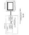
図2は、ビデオソース200とビデオディスプレイユニット204とを接続するために使用される、図1に図示したシステム100に基づくシステム200を例示している。例示した実施形態において、ビデオソース202は、デジタル画像(又はデジタルビデオソース)206及びアナログ画像(又はアナログビデオソース)208の一方又は両方を含むことができる。デジタル画像ソース206の場合、デジタルデータストリーム210がトランスミッタ102に提供されるが、アナログビデオソース208の場合には、結合されたA/Dコンバータユニット212が、アナログデータストリーム213を対応するデジタルデータストリーム214に変換する。デジタルデータストリーム214は、その後、トランスミッタ102によって、デジタルデータストリーム210とほぼ同じ形で処理される。ディスプレイユニット204は、アナログタイプのディスプレイ又はデジタルタイプのディスプレイにすることが可能であり、或いは一部のケースでは、提供されたアナログ又はデジタル信号のどちらでも処理できる。いずれの場合においても、ディスプレイユニット204は、レシーバとディスプレイ218、及びアナログタイプのディスプレイの場合にはD/Aコンバータユニット220とのインタフェースをとるディスプレイインタフェース216を含む。説明する実施形態において、ビデオソース202は、任意の数の形態(パーソナルデスクトップコンピュータ、デジタル又はアナログテレビ、セットトップボックス、その他)をとることが可能であり、ビデオディスプレイユニット104は、ビデオディスプレイ(LCD型ディスプレイ、CRT型ディスプレイ、その他)の形態をとることができる。 FIG. 2 illustrates a
しかしながら、ビデオソース又はビデオシンクのタイプに関係なく、様々なデータストリームは、物理リンク106上での伝送の前に(必要に応じて)デジタル化及びパケット化され、物理リンク106は、等時性データストリームのための単方向メインリンク222と、リンク設定及びビデオソース202とビデオディスプレイ204との間でのその他のデータトラフィック(様々なリンク管理情報、ユニバーサルシリアルバス(USB)データ、その他)のための双方向補助チャネル224とを含む。 However, regardless of the type of video source or video sink, the various data streams are digitized and packetized (as needed) prior to transmission over the
メインリンク222は、これにより、多数の等時性データストリーム(多数のビデオ/グラフィックストリーム及びマルチチャネルオーディオストリーム)を同時に伝送することができる。説明する実施形態において、メインリンク222は、多数の異なる仮想チャネルを含み、仮想チャネルのそれぞれは、数ギガビット/秒(Gbps)で等時性データストリーム(非圧縮グラフィック/ビデオ及びオーディオデータ)を転送できる。そのため、論理的な観点では、メインリンク222は、単一の物理パイプとして捉えられ、この単一の物理パイプ内部では、多数の仮想パイプを確立できる。これにより、論理データストリームが物理チャネルに割り当てられるのではなく、各論理データストリームが自分の論理パイプ(即ち、上記の仮想チャネル)において伝送される。 The
説明する実施形態において、メインリンク222の速度又は転送レートは、リンク条件を補償するために調整可能である。例えば、一実施において、メインリンク222の速度は、一チャネル当たり、最も遅い速度である約1.0Gbps〜約2.5Gbpsに近い範囲において、約0.4Gbpsの増分で調整できる(図3参照)。一チャネル当たり2.5Gbpsにおいて、メインリンク222は、単一のチャネル上で、SXGA 60Hzを一ピクセル当たり18ビットの色深度でサポートできる。チャネル数の減少により、相互接続のコストが減少するだけでなく、ポータブルデバイス及びその他といった電力に敏感な用途にとって重要な考慮事項(及び望ましい状態)である電力消費量の減少も発生することに留意されたい。しかしながら、チャネル数を四本に増加させることで、メインリンク222は、60HzのWQSXGA(3200×2048)を一ピクセル当たり24ビットの色深度で、或いは60HzのQSXGA(2560×2048)を一ピクセル当たり18ビットの色深度で、データ圧縮することなくサポートできる。最低レートの一チャネル当たり1.0Gbpsでも、非圧縮HDTV(即ち、1080i又は720p)データストリームをサポートするために必要なチャネルは僅か二本である。 In the described embodiment, the speed or transfer rate of the
説明する実施形態において、メインリンクのデータレートは、その構成要素である仮想リンクの総帯域幅を上回る帯域幅となるものが選択される。インタフェースに送信されたデータは、ネイティブレートでトランスミッタに到達する。レシーバ104内の時間基準回復(TBR)ユニット226は、必要な場合には、メインリンクデータパケットに埋め込まれたタイムスタンプを使用して、ストリームのオリジナルのネイティブレートを再生する。しかしながら、図2Bに図示した適切に構成されたデジタルディスプレイデバイス232では、ディスプレイデータがリンクキャラクタクロックレートでディスプレイドライバ電子回路に送信されるため、時間基準回復は不要であり、これにより、必要なチャネル数は、ディスプレイの複雑性及びコストの相応の低減と共に、大幅に減少することに留意されたい。例えば、図2Cは、アレイ240内の選択された表示素子238を駆動するためにロウドライバ236と組み合わせて使用される様々なカラムドライバ234へ、ディスプレイデータが本質的にパイプラインされるため、時間基準回復が存在しない形で構成された例示的なLCDパネル232を表している。 In the described embodiment, the data rate of the main link is selected so as to have a bandwidth that exceeds the total bandwidth of the constituent virtual links. Data sent to the interface reaches the transmitter at the native rate. A time base recovery (TBR)
その他の実施形態では、リンクレート及びピクセル/オーディオクロックレートの単純な算出法について説明する。現時点で存在する全ての標準ピクセル/オーディオクロック周波数は、以下のマスタ周波数のサブセットであることが研究及び理解されている。
23.76GHz=210ラ33ラ57ラ111HzIn other embodiments, a simple method for calculating the link rate and the pixel / audio clock rate will be described. All standard pixel / audio clock frequencies present at present are studied and understood to be a subset of the following master frequencies:
23.76GHz = 210 La 33 La 57 La 111Hz
これは、ピクセル(又はオーディオ)クロックレートを、四つのパラメータA、B、C、及びDによって、次のように表現できることを意味する。
ピクセルクロックレート=2A*3B×5C×11D
A=4ビット、B=2ビット、C=3ビット、及びD=1ビットThis means that the pixel (or audio) clock rate can be expressed by the four parameters A, B, C, and D as follows:
Pixel clock rate = 2A * 3B × 5C × 11D
A = 4 bits, B = 2 bits, C = 3 bits, and D = 1 bit
リンクレート(8B/10B文字のような10ビット文字を使用するリンクにおいて、シリアルリンクビットレート/10)がピクセルクロックレートとは異なる可能性があるリンクについても、こうした四つのパラメータA’、B’、C’、及びD’によってリンクレートを定義することには利点がある。この利点は、リンククロックからピクセル/オーディオクロックを再生する際の容易さである。例えば、リンクレートがA’=6、B’=3、C’=7、及びD’=0に設定され、対応するリンクレートが135MHzであるとする。しかしながら、ピクセルクロックレートがA=8、B=3、C=6、及びD=0(=108MHz)に設定されると仮定すると、ピクセルクロックは、ピクセルクロックレートがリンクレート*22/51に等しくなるように、リンククロックから生成できる。 For links where the link rate (serial link bit rate / 10 in links using 10-bit characters such as 8B / 10B characters) may differ from the pixel clock rate, these four parameters A ′, B ′ It is advantageous to define the link rate by C ′ and D ′. The advantage is the ease with which the pixel / audio clock is recovered from the link clock. For example, assume that the link rate is set to A ′ = 6, B ′ = 3, C ′ = 7, and D ′ = 0, and the corresponding link rate is 135 MHz. However, assuming the pixel clock rate is set to A = 8, B = 3, C = 6, and D = 0 (= 108 MHz), the pixel clock is equal to the link rate * 22/51. It can be generated from the link clock.
時間基準回復を必要とするシステムを再び参照すると、時間基準回復ユニット226は、デジタルクロックシンセサイザとして実施してよい。非圧縮ビデオストリームについて、タイムスタンプは、パケットヘッダに格納され、下で更に詳細に説明するように20ビット値となる。一定のストリームにおいて、20ビットのうちの各四ビットが、各ヘッダにおいて連続的に格納される(TS3-0、TS7-4、TS11-8、TS15-12、TS19-16)。ネイティブストリーム周波数(Freq_native)は、次のように、リンク文字クロック周波数(Freq_link_char)から取得される。
Freq_native = Freq_link_char*(TS19-0)/220Referring back to systems that require time reference recovery, the time
Freq_native = Freq_link_char * (TS19-0) / 220
トランスミッタ102は、220サイクルのリンク文字クロック周波数期間においてネイティブストリームクロック数をカウントすることで、このタイムスタンプを生成する。カウンタは、220サイクルのリンク文字クロック毎に値を更新する。これら二つのクロックは互いに非同期であるため、タイムスタンプ値は、時間と共に1ずつ変化することになる。更新と更新との間に、トランスミッタ102は、一定のパケットストリームのヘッダにおいて、同じタイムスタンプを繰り返し送信する。タイムスタンプ値の(1カウントより大きい)急変は、レシーバによって、ストリームソースの不安定状態を示すものと解釈される。 The
オーディオストリームでは、タイムスタンプが通信されないことに留意されたい。この場合、ソースデバイスは、ディスプレイデバイスに対して、オーディオサンプルレートと一サンプル当たりのビット数とを通知する。下のようにオーディオレート及びリンク文字レートを決定することで、ディスプレイデバイスは、オリジナルのオーディオストリームレートを再生する。
オーディオレート=(オーディオサンプルレート)×(サンプル当たりビット数)×(チャネル数)Note that timestamps are not communicated in the audio stream. In this case, the source device notifies the display device of the audio sample rate and the number of bits per sample. By determining the audio rate and link character rate as follows, the display device reproduces the original audio stream rate.
Audio rate = (audio sample rate) x (bits per sample) x (number of channels)
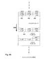
図4Aに図示したメインリンクデータパケット400は、図4Bに図示したようなメインリンクパケットヘッダ402を含み、パケットヘッダ402は、16ビットの形態であり、ビット3〜0はストリームID(SID)(最大ストリームカウントが16であることを示す)、ビット4はタイムスタンプ(TS)のLSBである。ビット4が1に等しい時、このパケットヘッダは、タイムスタンプ値の最下位の四ビットを有する(非圧縮ビデオストリームに対してのみ使用される)。ビット5は、ビデオフレームシーケンスビットであり、ビデオフレーム境界において「0」から「1」或いは「1」から「0」にトグルするフレームカウンタの最下位ビットの役割を果たす(非圧縮ビデオストリームに対してのみ使用される)。ビット7及び6はリザーブされるが、ビット8〜10は、先行する八ビットのエラーをチェックする四ビットCRC(CRC)となる。ビット15〜12は、タイムスタンプ/ストリームID反転(TSP/SIDn)であり、非圧縮ビデオでは、20ビットタイムスタンプ値のうちの四ビットとして使用される。 The main link data packet 400 illustrated in FIG. 4A includes a main
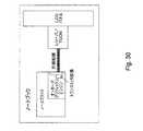
本発明のインタフェースの利点の一つは、それぞれ異なる形式にすることが可能な異なるデータストリームを多重化し、更に、一定のメインリンクデータパケットに多数のサブパケットを包含させる能力である。例えば、図5Aは、本発明の実施形態による、サブパケットエンクロージャ及び複数パケット多重化を提供するように構成されたシステム500を図示している。システム500は、図2に図示したシステム200の特定の実施形態であり、したがって、本発明の範囲及び意図のいずれかを限定するものと解釈されるべきではないことに留意されたい。システム500は、トランスミッタ102に含まれ、ストリーム1補足データストリーム504をデータストリーム210に組み合わせて多重化データストリーム506を形成するために使用される、ストリームソースマルチプレクサ502を含む。多重化データストリーム506は、その後、リンク層マルチプレクサ508に転送される。任意の数のデータストリームを組み合わせ、多重化メインリンクストリーム510を形成し、多重化メインリンクストリーム510は、多数のデータパケット512で形成され、データパケット512の一部は、内部に封入された任意の数のサブパケット514を含んでもよい。リンク層デマルチプレクサ516は、ストリームID(SID)と関連サブパケットヘッダとに基づいて、多重化データストリーム510を分割し、構成要素であるデータストリームとし、一方、ストリームシンクデマルチプレクサ518は、サブパケットに収容されたストリーム1補足データストリームを更に分割する。 One advantage of the interface of the present invention is the ability to multiplex different data streams, each of which can be in a different format, and to include a number of subpackets in a given main link data packet. For example, FIG. 5A illustrates a
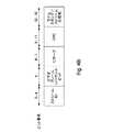
図6は、三本のストリームがメインリンク222上で多重化される時の図5に図示したストリーム510の例として、多重化メインリンクストリーム600の高レベル図を図示している。この例の三本のストリームは、UXGAグラフィックス(ストリームID=1)と、1280×720pビデオ(ストリームID=2)と、オーディオ(ストリームID=3)とである。メインリンクパケット400の小さなパケットヘッダサイズは、パケットオーバヘッドを最小化し、結果として、非常に高いリンク効率を生み出す。パケットヘッダをこれほど小さくできるのは、メインリンク222でのパケットの伝送前に、補助チャネル224を介して、パケット属性が通信されるためである。 FIG. 6 illustrates a high level diagram of the multiplexed
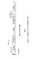
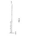
一般的に言えば、非圧縮ビデオデータストリームはビデオブランキング期間に対応するデータアイドル期間を有するため、サブパケットエンクロージャは、メインパケットストリームが非圧縮ビデオである時に効果的な方式となる。したがって、非圧縮ビデオストリームの形態であるメインリンクトラフィックは、この期間中に一連のNull特殊文字を含むことになる。様々なデータストリームを多重化する能力を十分に利用することで、本発明の特定の実施は、ソースストリームがビデオデータストリームである時に、様々な方法を使用して、メインリンクレートとピクセルデータレートとの間の差異を補正する。例えば、図7に例示したように、ピクセルデータレートは、0.5Gb/秒となり、2ns毎にピクセルデータのビットが送信されるようになる。この例において、リンクレートは、1.25Gb/秒に設定されており、0.8ns毎にピクセルデータのビットが送信されるようになっている。ここで、トランスミッタ102は、図8に例示したように、ピクセルデータ間に特殊文字を散在させる。二つの特殊文字は、ピクセルデータの第一のビットP1とピクセルデータの第二のビットP2との間に配置される。特殊文字によって、レシーバ104は、ピクセルデータの各ビットを区別することが可能となる。ピクセルデータのビット間に特殊文字を散在させることで、更に、リンクが同期を維持可能な安定したデータのストリームが形成される。この例において、特殊文字はNull文字である。こうした方法では、リンクレートが十分に高速であるため、ラインバッファは不要であり、小さなFIFOのみが必要となる。しかしながら、受信側では、ビデオ信号を再構築するために、相対的に多くのロジックが必要となる。レシーバは、特殊文字の開始及び終了の時期を認識する必要がある。 Generally speaking, since the uncompressed video data stream has a data idle period corresponding to the video blanking period, the sub-packet enclosure is an effective method when the main packet stream is uncompressed video. Thus, main link traffic in the form of an uncompressed video stream will contain a series of Null special characters during this period. By taking full advantage of the ability to multiplex different data streams, certain implementations of the present invention use different methods when the source stream is a video data stream, and use the main link rate and the pixel data rate. To compensate for the difference between For example, as illustrated in FIG. 7, the pixel data rate is 0.5 Gb / sec, and bits of pixel data are transmitted every 2 ns. In this example, the link rate is set to 1.25 Gb / sec, and a bit of pixel data is transmitted every 0.8 ns. Here, as illustrated in FIG. 8, the
散在法の代替は、ピクセルデータの連続ビットを、ヌル値のような特殊文字と交互に配置することである。例えば、P1からP4をトランスミッタ104に含まれるラインバッファに供給し、その後、更なるピクセルデータが利用可能になるまで、一つ以上のヌル値をバッファに供給することができる。こうした実施には、上記の散在法よりも相対的に大きなバッファスペースが必要となる。こうした多くの実施では、相対的に高速なリンク速度のため、ラインバッファを満たすのに必要な時間は、ラインバッファが一杯になった後でデータを伝送するのに必要な時間を上回ることになる。 An alternative to the sparse method is to interleave consecutive bits of pixel data with special characters such as null values. For example, P1 through P4 can be supplied to a line buffer included in the
図5Aを参照して説明したように、本発明のインタフェースの利点の一つは、様々なデータストリームを多重化する能力だけでなく、更に特定のメインリンクデータパケット内に任意の数のサブパケットを封入することである。図9Aは、本発明の実施形態による、代表的なサブパケット900を図示している。サブパケット900は、サブパケットヘッダ902を含み、説明する実施形態において、サブパケットヘッダ902は2バイトであり、SPS(サブパケットスタート)特殊文字を伴う。サブパケット900が封入されるメインリンクデータパケットがサブパケット900に加えてパケットペイロードを含む場合には、SPE(サブパケットエンド)特殊文字によって、サブパケット900の終了を示す必要がある。そうでない場合には、メインパケットの終了(図9Bに図示した例ではCOM文字に続くことで示される)が、サブパケット902と、封入するメインパケットとの両方の終了を示す。しかしながら、サブパケットは、サブパケットを封入するメインパケットがペイロードを有していない時、SPEで終了する必要はない。図9Bは、本発明の実施形態による、メインリンクパケット内の例示的なサブパケット形式を図示している。ヘッダフィールド及びサブパケットペイロードの定義は、サブパケット902を使用する特定のアプリケーションのプロファイルに応じて変化することに留意されたい。 As described with reference to FIG. 5A, one of the advantages of the interface of the present invention is not only the ability to multiplex various data streams, but also any number of subpackets within a particular main link data packet. Is to enclose. FIG. 9A illustrates an exemplary subpacket 900 according to an embodiment of the present invention. The subpacket 900 includes a
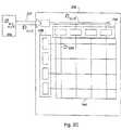
特に有用なサブパケットエンクロージャの使用法の例は、図10に図示した非圧縮グラフィックス画像1000の選択的リフレッシュである。フレーム1002全体の属性(水平/垂直合計、画像幅/高さ、その他)については、ストリームが有効であり続ける限り、こうした属性は一定のままであるため、補助チャネル224を介して通信されることになる。選択的リフレッシュ動作では、画像1000の一部1004のみが、ビデオフレーム毎に更新される。更新された(複数の)長方形(即ち、部分1004)の四つのX−Y座標は、フレーム毎に伝送する必要があり、これは長方形座標の値がフレーム毎に変化するためである。別の例は、256色グラフィックデータに必要なカラールックアップテーブル(CLUT)の伝送であり、この場合、八ビットピクセルデータが256エントリCLUTに対するエントリとなり、CLUTのコンテンツは、動的に更新されなければならない。 An example of a particularly useful subpacket enclosure usage is the selective refresh of the
単一の双方向補助チャネル224は、リンク設定に有用な、メインリンクの動作をサポートする様々なサポート機能のための経路で、更にUSBトラフィック等の補助アプリケーションデータを伝送する経路を提供する。例えば、補助チャネル224により、ディスプレイデバイスは、ソースデバイスに、同期消失等のイベント、欠落パケット、及びトレーニングセッションの結果(下記)を通知できる。例えば、特定のトレーニングセッションが失敗した場合、トランスミッタ102は、失敗したトレーニングセッションの事前に選択された或いは決定された結果に基づいて、メインリンクレートを調整する。これにより、調整可能な高速メインリンクと、相対的に低速で非常に信頼性の高い補助チャネルとを組み合わせることで形成される閉ループは、様々なリンク条件での堅牢な動作を可能にする。一部のケースでは(図5Bに図示した例)、データをソースデバイス202からシンクデバイス204に転送するメインリンク222の帯域幅の一部522と、シンクデバイス204からソースデバイス202への単方向バックチャネル524とを使用して、論理双方向補助チャネル520を確立できることに留意されたい。一部の応用では、この論理双方向補助チャネルの使用は、図5Aにおいて説明した半二重双方向チャネルを使用することより望ましい場合がある。 A single bi-directional
実際のパケットデータストリームの伝送を開始する前に、トランスミッタ102は、概念においてモデムのリンク設定に類似するリンクトレーニングセッションを通じて、安定したリンクを確立する。リンクトレーニング中、メインリンクトランスミッタ102は、確実なビット/文字ロックが達成可能かをレシーバ104が判断できるように、所定のトレーニングパターンを送信する。説明する実施形態では、トランスミッタ102とレシーバ104との間でのトレーニングに関連するハンドシェイクが、補助チャネル上で実行される。本発明の実施形態による、リンクトレーニングパターンの例は、図11に図示される。例示のように、トレーニングセッション中、段階1は、イコライザを最適化するためにレシーバによって使用される最短のランレングスを表し、一方、段階2は、最長のものである。段階3において、ビットロック及び文字ロックは、両方とも、リンク品質が妥当である限り達成される。通常、トレーニング期間は、約10msであり、この時間内に、約107ビットのデータが送信される。レシーバ104は、確実なロックを達成しない場合、補助チャネル224を介してトランスミッタ102に通知を行い、トランスミッタ102は、リンクレートを低下させて、トレーニングセッションを繰り返す。トレーニングセッション経路を提供することに加え、補助チャネル224は、更に、メインリンクパケットストリームの説明を伝送するために使用可能であり、これにより、メインリンク222でのパケット伝送のオーバヘッドは大幅に減少する。更に、補助チャネル224は、全てのモニタで見られるディスプレイデータチャネル(DDC)の代わりに、拡張表示識別データ(EDID)情報を伝送するように構成できる(EDIDは、VESA規格のデータ形式で、ベンダ情報と、最大画像サイズと、色特性と、工場プリセットタイミングと、周波数範囲限界と、モニタ名及びシリアル番号の文字列とを含め、モニタ及びその機能に関する基本情報を含む。情報は、ディスプレイに格納され、モニタとPCグラフィックスアダプタとの間に位置するDDCを通じてシステムと通信するために使用される。システムは、この情報を構成の目的で使用するため、モニタ及びシステムは連動が可能となる)。拡張プロトコルモードと呼ばれるものにおいて、補助チャネルは、キーボード、マウス、及びマイクロフォンといった追加的なデータタイプをサポートするために、必要に応じて、非同期パケット及び等時性パケットの両方を伝送できる。 Prior to starting the transmission of the actual packet data stream, the
図12は、本発明の実施形態による、データスケジューラ1202を有する代表的なシステム1200を図示している。システム1200は、図5A及び5Bを参照して説明したシステムに基づいており、そのため、本発明の任意の数の実施の一つに過ぎないと考えるべきであることに留意されたい。したがって、ストリームスケジューラ1202は、ビデオソース202に組み込まれるか、或いは結合され、続いて、マルチプレクサ1204と、スケジューラサイクル時間Tschedと呼ばれる期間中にリンクデータストリーム1208を送り込むのに使用される着信データストリーム(S1、S2、及びS3)の部分のみを格納するのに適したデータバッファ1206とに結合される。説明する実施形態において、データバッファ1206は、FireWireTM等の等時性ビデオ転送プロトコルで代表的な60Kバイトを超えるものとは対照的に、通常数十バイト程度のサイズである。これにより、リンク効率(利用可能帯域幅で除算したデータストリームのペイロード帯域幅合計の比較に基づく)は、およそ90%程度以上となる。FIG. 12 illustrates an
説明する実施形態において、リンクデータストリーム1208は、データストリームS1、S2、及びS3のそれぞれからのサイズデータパケットP1、P2、及びP3(サイズは、リンク帯域幅との関係における各データストリームの相対帯域幅を反映する)を組み合わせるために時分割多重化を使用することで、スケジューラ1202によって形成される。以前に説明したように、各データパケットのサイズは、特定のデータストリームビットレート(SBR)とリンクビットレート(LBR)との関数である。特に、特定のデータストリームビットレートが大きくなれば、表1の例で示したように、特定のデータパケットは大きくなる。例えば、リンクビットレートLBRが2.5Gbps程度であり、最大パケットサイズがおよそ80リンクシンボル程度であり(一リンクシンボルは、一リンククロック当たりのデータ単位として定義され、通常は4nsである)、表1の前提(即ち、SBR1が1.05Gbps、SBR2が0.3125Gbps、SBR3が0.25Gbps)を使用する場合、ストリームS1に関連するデータパケットP1は、32リンクシンボルとなり、一方、ストリームS2及びS3に関連するデータパケットP2及びP3は、それぞれ10リンクシンボル及び8リンクシンボルとなる。各スケジューラサイクル時間Tschedの開始時には、スケジューラ1202が、通常は2リンクシンボル程度のサイズである、レシーバ204用のアライメントツールを提供するレーン間アライメントパケット(ILA)を挿入することに留意されたい。そのため、この例においては、スケジューラサイクル時間Tschedは、(32+10+8+2)52リンクシンボル程度となる(各リンクシンボルが約4nsを表す時、約208nsと解釈される)。In the described embodiment, the
更に、各データパケットPは、次のようなストリームビットレート(SBR)及びリンクビットレート(LBR)に関するデータシンボルDの数とスタッフィングシンボルNとの関連アクティブデータ比を有することに留意されたい。
SBR/LBR = D/(D+N)Further, note that each data packet P has an associated active data ratio between the number of data symbols D and the stuffing symbol N for the stream bit rate (SBR) and link bit rate (LBR) as follows.
SBR / LBR = D / (D + N)
したがって、データストリームが追加(又は削除)され、スケジューラサイクル時間Tschedの増加(又は減少)が生じる状況においては、データシンボルDの数との関係において、スタッフィングシンボルNの数を変化させることで、パケットサイズPは、一定状態を維持する。データストリームの追加(又は削除)により、特定のパケットサイズは同じ状態を維持し、他のデータストリーム及びスケジューラサイクル時間Tschedは増加(又は減少)するため、スタッフィングシンボルNの数は、Tschedの変化に比例して増加(又は減少)する。単一のデータストリームのみが残る「縮退」のケースでは、スタッフィングシンボルNは存在しなくなる。Therefore, in a situation where a data stream is added (or deleted) and an increase (or decrease) in the scheduler cycle time Tsched occurs, by changing the number of stuffing symbols N in relation to the number of data symbols D, The packet size P remains constant. Due to the addition (or deletion) of the data stream, the specific packet size remains the same, and the other data streams and the scheduler cycle time Tsched increase (or decrease), so the number of stuffing symbols N is Tsched Increase (or decrease) in proportion to the change. In the “degenerate” case where only a single data stream remains, the stuffing symbol N does not exist.
図13は、実施形態によるデータストリーム1210の更に詳細な部分1300を図示している。特に、図13は、表1に示した値を使用したデータストリーム1208のデータシンボルDとスタッフィングシンボルNの配置を図示している。更に、特定のデータストリームを動的に追加又は削除することで、残りのデータストリームの特定のパケットサイズが影響されないままとなることに留意されたい。したがって、図14は、20リンクシンボルのパケットサイズP4に対応する0.625Gbpsのストリームビットレートを有する第四のデータストリームS4の追加を例示しており、この結果、Tschedは52から72リンクシンボル(4nsに等しいリンクシンボルでは288nsに相当する)に増加する。しかしながら、特定のパケットサイズP1、P2、及びP3を一定に保つために、スタッフィングシンボルNの数は、各データパケットについて増加する。反対に、(例えばS3のような)データストリームが削除される場合、スケジューラサイクル時間Tschedは、スタッフィングシンボルNの数に関係するデータシンボルDの数の相応の増加に応じて減少することになる。一つ以外の全データストリームが削除される「縮退」のケースでは、残存するデータパケットは、スタッフィングシンボルNを有しておらず、何らかのバッファの必要性も存在せず、これにより、上で説明したラスタスキャントランスポートプロトコルをシミュレートする。FIG. 13 illustrates a more detailed portion 1300 of the data stream 1210 according to an embodiment. In particular, FIG. 13 illustrates the arrangement of data symbols D and stuffing symbols N in the
リンクデータストリーム1208が(図15に図示するような)単一の非圧縮ビデオストリームである時の縮退接続のケースにおいて、ILAパケットは、S1のアイドル期間(水平ブランキング領域)に配置され、アクティブな表示領域は、その後、データシンボルDとスタッフィングシンボルNとの混合によって表現される(図16参照)。 In the case of a degenerate connection when the
更に、特定のデータストリームに関係しないデータシンボルと関連させて、特定のデータストリームのデータシンボルDの数をカウントすることで、問題のデータストリームのストリームクロックが提供されることから、データシンボルDの相対数が、埋め込みタイムスタンプを提供することに留意されたい。例えば、図13に図示したケースにおいて、回復のために、特定のデータストリームのストリームクロックFstream_clkは、単純に、スタッフィングシンボル及びストリームデータシンボルの合計数(P)と比較したストリームデータシンボルの数(M)を確定することで決定できる。更に詳しくは、ストリームクロックFstream_clkは、次のように決定される。
Fstream_clk= (M/P)*Flink_clk
ここで、M及びPは、レシーバ204によって測定できる。In addition, counting the number of data symbols D in a particular data stream in association with data symbols not related to the particular data stream provides a stream clock for the data stream in question, so Note that the relative number provides an embedded timestamp. For example, in the case illustrated in FIG. 13, for recovery, the stream clock Fstream_clk for a particular data stream is simply the number of stream data symbols (P) compared to the total number of stuffing symbols and stream data symbols (P). It can be determined by confirming M). More specifically, the stream clock Fstream_clk is determined as follows.
Fstream_clk = (M / P) * Flink_clk
Here, M and P can be measured by the
図17は、本発明の実施形態による、多数のデータストリームをスケジュールするプロセス1700を詳細に表すフローチャートを図示している。プロセス1700は、1702で、トランスミッタがストリーム属性データをレシーバに送信することで開始される。説明する実施形態において、属性データは、補助チャネルを経由して送信される。次に、1704において、レシーバは、着信データストリームを受領及び処理するために(利用可能な場合)十分なリソースを割り当てる。トランスミッタがデータストリーム1706を受領した後、ストリームトランスポートスケジューラは、1708において、リンクデータストリームを形成し、一方、1710において、リンクデータストリームは、メインリンクを経由して、トランスミッタによりレシーバへ送信される。次に、1712において、追加データストリームが追加され、1714において、レシーバが追加対象のデータストリームの受領及び処理の両方を行える場合、1716において、新しいデータストリームは、以前に伝送されたデータストリームのデータパケットサイズが一定に維持されるという点でトランスペアレントに追加される。 FIG. 17 illustrates a flowchart detailing a process 1700 for scheduling multiple data streams, in accordance with an embodiment of the present invention. Process 1700 begins at 1702 with a transmitter sending stream attribute data to a receiver. In the described embodiment, the attribute data is transmitted via an auxiliary channel. Next, at 1704, the receiver allocates sufficient resources (if available) to receive and process the incoming data stream. After the transmitter receives the
図18は、本発明の実施形態による、リンクデータストリームを形成するプロセス1800を詳細に表すフローチャートを図示している。処理1800は、処理1708の形成動作1708の特定の実施であることに留意されたい。したがって、トランスポートスケジューラは、1802において、メインリンクのリンクビットレートを決定し、1804において、トランスミッタからレシーバへのリンクを経由してトランスポートされるべきデータストリームのそれぞれについて、ストリームビットレートを決定する。次に1806において、それぞれのデータストリームのためのパケットサイズが、ストリームビットレートと、リンクビットレートと、所定の最大パケットサイズとに基づいて決定される。次に1808において、それぞれのデータストリームのためのデータパケットが、それぞれ多数のデータシンボルとスタッフィングシンボルとを含む状態で形成される。データパケットが形成されると、単一のトランスポートスケジューラサイクル時間中に、トランスポートスケジューラは、1810において、レシーバに送信されるべきデータストリームのそれぞれからのデータパケットを(時分割多重化を使用して)連結し、1812において、連結されたデータパケットにレーン間アライメントパケットを追加する。1814において、トランスポートスケジューラは、連結されたデータパケットをレシーバに伝送するために、トランスミッタに信号を送り、1816において決定されるような伝送の中止まで、1808〜1814を繰り返す。 FIG. 18 illustrates a flowchart detailing a process 1800 for forming a link data stream according to an embodiment of the present invention. Note that process 1800 is a specific implementation of forming
図19は、本発明の実施形態による、システム200の論理層構造1900を例示している。正確な実施は用途に応じて変化してよいが、一般に、ソース(ビデオソース202等)は、トランスミッタハードウェアを含むソース物理層1902と、多重化ハードウェア及びステートマシン(又はファームウェア)を含むソースリンク層1904と、オーディオ/ビジュアル/グラフィックスハードウェア及び関連ソフトウェアのようなデータストリームソース1906とにより形成されることに留意されたい。同様に、ディスプレイデバイスは、物理層1908(様々なレシーバハードウェアを含む)と、逆多重化ハードウェア及びステートマシン(又はファームウェア)を含むシンクリンク層1910と、ディスプレイ/タイミングコントローラハードウェア及びオプションのファームウェアを含むストリームシンク1912とを含む。ソースアプリケーションプロファイル層1914は、ソースがリンク層1904と通信する形式を定義し、同様に、シンクアプリケーションプロファイル層1916は、シンク1912がシンクリンク層1910と通信する形式を定義する。 FIG. 19 illustrates a logical layer structure 1900 of the
次に、様々な層について、更に詳細に説明する。 Next, the various layers will be described in more detail.
ソースデバイス物理層:
説明する実施形態において、ソースデバイス物理層1902は、電気副層1902−1と論理副層1902−2とを含む。電気副層1902−1は、ホットプラグ/アンプラグ検出回路と、ドライバ/レシーバ/終端レジスタと、パラレル−シリアル/シリアル−パラレル変換と、スペクトラム拡散対応PLLとのような、インタフェース初期化/動作のための全回路を含む。論理副層1902−2は、パケット化/逆パケット化と、データスクランブル化/スクランブル解除と、リンクトレーニング用パターン生成と、時間基準回復回路と、メインリンク222用の(図13に例が図示された)256リンクデータ文字及び12の制御文字を提供する8B/10B(ANSI X3.230-1994第11条において規定される)及び補助チャネル224用のManchester II(図21参照)のようなデータエンコード/デコードとのための回路を提供する。Source device physical layer:
In the described embodiment, the source device
8B/10Bエンコードアルゴリズムは、例えば、米国特許第4,486,739号において説明されており、参照により本明細書に組み込まれることに留意されたい。当業者に知られている通り、8B/10Bコードは、シリアル伝送のために8ビットデータブロックを10ビットコードワードにエンコードするブロックコードである。加えて、8B/10B伝送コードは、1及び0のバイト幅ストリームを、最大ランレングスが5である1及び0のDCバランスストリームに変換する。こうしたコードは、トランシーバ110等のレシーバによる信頼性の高いクロック回復を可能にするのに十分な信号遷移を提供する。更に、DCバランスデータストリームは、光ファイバ及び電磁線接続にとって有利となる。シリアルストリームにおける1及び0の平均数は、均等又は均等に近いレベルに維持される。8B/10B伝送コードは、1及び0の数の格差を、6及び4ビットブロック境界に渡って、−2、0、又は2となるように抑制する。このコード方式は、更に、コマンドコードと呼ばれる、信号送信用の追加コードを実施する。 It should be noted that the 8B / 10B encoding algorithm is described, for example, in US Pat. No. 4,486,739 and is incorporated herein by reference. As known to those skilled in the art, the 8B / 10B code is a block code that encodes an 8-bit data block into a 10-bit codeword for serial transmission. In addition, the 8B / 10B transmission code converts 1 and 0 byte wide streams into 1 and 0 DC balanced streams with a maximum run length of 5. Such code provides sufficient signal transitions to allow reliable clock recovery by a receiver such as
非圧縮ディスプレイデータが示す反復ビットパターンを回避する(したがって、EMIを低減する)ために、メインリンク222上で伝送されるデータは、8B/10Bエンコードの前に、まずスクランブル化されることに留意されたい。トレーニングパケットと特殊文字とを除き、全データがスクランブル化されることになる。スクランブル化機能は、リニアフィードバックシフトレジスタ(LFSR)により実施される。データ暗号化が有効である時、LFSRシードの初期値は、暗号鍵セットに応じて決まる。暗号化のないスクランブル化の場合、初期値は固定されることになる。 Note that data transmitted on
データストリーム属性は補助チャネル224上で伝送されるため、メインリンクパケットヘッダは、ストリーム識別番号の役割を果たし、これにより、オーバヘッドを大幅に減らし、リンク帯域幅を最大化する。更に、メインリンク222と補助リンク224とは、どちらも別個のクロック信号線を有していないことに留意されたい。これにより、メインリンク222及び補助リンク224上のレシーバは、データをサンプリングし、着信データストリームからクロックを抽出する。レシーバ電気副層内の任意の位相同期ループ(PLL)回路のための高速位相同期は、補助チャネル224が半二重双方向であり、トラフィックの方向が頻繁に変化するため、重要となる。したがって、補助チャネルレシーバのPLLは、Manchester II(MII)コードの頻繁かつ均一な信号遷移の結果、僅か16データ期間で位相同期を行う。 Since the data stream attributes are transmitted on the
リンク設定時、メインリンク222のデータレートは、補助チャネル224上でのハンドシェイクを使用して交渉される。このプロセス中には、トレーニングパケットの既知のセットが、メインリンク222上において、最高リンク速度で送信される。成功又は失敗は、補助チャネル224を介して、トランスミッタ102に連絡を返す。トレーニングが失敗した場合、メインリンク速度を低減し、成功するまでトレーニングを繰り返す。これにより、ソース物理層1902は、ケーブルのトラブルに対する抵抗力が更に増し、したがって、モニタアプリケーションの外部ホストとして更に適したものとなる。しかしながら、従来のディスプレイインタフェースとは異なり、メインチャネルのリンクデータレートは、ピクセルクロックレートから切り離される。リンクデータレートは、リンク帯域幅が伝送ストリームの総帯域幅を上回るように設定される。 At link setup, the data rate of the
ソースデバイスリンク層:
ソースリンク層1904は、リンクの初期化及び管理を扱う。例えば、モニタの電源投入時、或いはソース物理層1902からのモニタケーブルの接続時に生成されるホットプラグ検出イベントを受領すると、ソースデバイスリンク層1904は、補助チャネル224上でのやり取りを介して、レシーバの能力を評価し、トレーニングセッションで決定されるような最大メインリンクデータレートと、レシーバ上の時間基準回復ユニットの数と、両側で利用可能なバッファサイズと、USB拡張機能の可用性とを決定し、その後、ストリームソース1906に、関連するホットプラグイベントを通知する。加えて、ストリームソース1906からの要求時、ソースリンク層1904は、表示能力(EDID又は同等のもの)を読み出す。正常動作中、ソースリンク層1904は、補助チャネル224を介してレシーバ104にストリーム属性を送信し、メインリンク222が要求データストリームを処理するのに十分なリソースを有するかをストリームソース1904に通知し、同期消失及びバッファオーバフローといったリンク障害イベントをストリームソース1904に通知し、ストリームソース1904によって提出されたMCCSコマンドをレシーバに対して、補助チャネル224を介して送信する。ソースリンク層1904とストリームソース/シンクとの間の全ての通信では、アプリケーションプロファイル層1914において定義された形式を使用する。Source device link layer:
The
アプリケーションプロファイル層(ソース及びシンク):
一般に、アプリケーションプロファイル層は、ストリームソース(又はシンク)が関連するリンク層とインタフェースする際の形式を定義する。アプリケーションプロファイル層によって定義された形式は、以下のカテゴリ、即ち、アプリケーション独立形式(リンク状態問い合わせのためのリンクメッセージ)及びアプリケーション従属形式(メインリンクデータマッピング、レシーバのための時間基準回復数式、及び該当する場合のシンク能力/ストリーム属性メッセージサブパケット形式)に分類される。アプリケーションプロファイル層は、以下の色形式、即ち、24ビットRGB、16ビットRG2565、18ビットRGB、30ビットRGB、256色RGB(CLUTに基づく)、16ビットCbCr422、20ビットYCbCr422、及び24ビットYCbCr444をサポートする。Application profile layer (source and sink):
In general, the application profile layer defines the format in which the stream source (or sink) interfaces with the associated link layer. The formats defined by the application profile layer include the following categories: application-independent formats (link messages for link state queries) and application-dependent formats (main link data mapping, time base recovery formulas for receivers, and applicable) The sync capability / stream attribute message subpacket format. The application profile layer has the following color formats: 24-bit RGB, 16-bit RG2565, 18-bit RGB, 30-bit RGB, 256-color RGB (based on CLUT), 16-bit CbCr422, 20-bit YCbCr422, and 24-bit YCbCr444. to support.
例えば、ディスプレイデバイスのアプリケーションプロファイル層(APL)1914は、本質的には、インタフェース100に送信される又はインタフェース100から受領されるデータの提示形式を含む、メインリンク222上でのストリームソース/シンク通信のための形式を記述するアプリケーションプログラミングインタフェース(API)である。APL1914の一部の態様(電力管理コマンド形式等)は、基本モニタ機能であるため、インタフェース100のあらゆる使用法において共通である。データマッピング形式及びストリーム属性形式といった、その他の非基本モニタ機能は、アプリケーション、或いは伝送対象である等時性ストリームのタイプに固有のものとなる。アプリケーションに関係なく、ストリームソース1904は、ソースリンクレイヤ1914に問い合わせを行い、メインリンク222上で何らかのパケットストリーム伝送を開始する前に、メインリンク222が(複数の)保留中のデータストリームを処理できるかを確認する。 For example, the display device's application profile layer (APL) 1914 essentially includes stream source / sink communication over the
メインリンク222が(複数の)保留中のデータストリームを処理できると判断された時、ストリームソース1996は、ソースリンク層1914にストリーム属性を送信し、その後、ストリーム属性は補助チャネル224上でレシーバに伝送される。こうした属性は、特定のストリームのパケットを識別し、ストリームからオリジナルのデータを復元し、ストリームのネイティブデータレートにフォーマットし直すために、レシーバによって使用される情報である。データストリームの属性は、アプリケーション従属である。 When the
望ましい帯域幅がメインリンク222上で利用できない場合には、ストリームソース1914は、例えば、画像リフレッシュレート又は色深度を低減することで、修正措置を講じてもよい。 If the desired bandwidth is not available on the
ディスプレイデバイス物理層:
ディスプレイデバイス物理層1916は、ディスプレイデバイスリンク層1910とディスプレイデバイスAPL1916とを、リンクデータの送受信に使用される信号伝送技術から分離させる。メインリンク222及び補助チャネル224は、独自の物理層を有し、それぞれの物理層は、論理副層とコネクタ仕様を含む電気副層とで構成される。例えば、半二重双方向補助チャネル224は、図22に示すように、リンクの各端部にトランスミッタとレシーバとの両方を有する。補助リンクトランスミッタ2902には、論理副層1908−1によってリンク文字が提供され、その後、リンク文字はシリアル化され、対応する補助リンクレシーバ2904に伝送される。レシーバ2904は、次に、補助リンク224からのシリアル化されたリンク文字を受領し、リンク文字クロックレートでデータを非シリアル化する。ソース論理副層の主要な機能は、信号エンコードと、パケット化と、(EMI低減のための)データスクランブル化と、トランスミッタポート用のトレーニングパターン生成とを含むことに留意されたい。一方、レシーバポートについて、レシーバ論理副層の主要な機能は、信号デコードと、非パケット化と、データスクランブル解除と、時間基準回復とを含む。Display device physical layer:
The display device
補助チャネル:
補助チャネル論理副層のような機能は、データエンコード/デコードと、データのフレーム化/非フレーム化とを含み、補助チャネルプロトコルには二種類のオプションが存在し、スタンドアロンプロトコル(ポイントツーポイントトポロジにおけるリンク設定/管理機能に限定される)は、リンク層ステートマシン又はファームウェアによって管理可能な軽量プロトコルと、USBトラフィック等の他のデータタイプ及びデイジーチェイン方式でつながれたデバイス等のトポロジをサポートする拡張プロトコルとになる。データエンコード及びデコード方式はプロトコルに関係なく同一だが、データのフレーム化は二種類の間で異なることに留意されたい。Auxiliary channel:
Functions such as the auxiliary channel logical sublayer include data encoding / decoding and data framing / unframing, and there are two options for the auxiliary channel protocol, stand-alone protocol (in a point-to-point topology). (Limited to link setup / management functions) is a lightweight protocol that can be managed by a link layer state machine or firmware and other protocols that support other data types such as USB traffic and topologies such as devices connected in a daisy chain It becomes. Note that the data encoding and decoding schemes are the same regardless of the protocol, but the data framing is different between the two types.
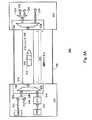
更に図29を参照すると、補助チャネル電気副層は、トランスミッタ2902及びレシーバ2904を含む。トランスミッタ2902には、論理副層によってリンク文字が提供され、リンク文字はシリアル化され外部に伝送される。レシーバ2904は、シリアル化されたリンク文字をリンク層から受領し、その後、リンク文字クロックレートで非シリアル化する。補助チャネル224の正及び負の信号は、図示したように、リンクの各端部で、50オーム終端抵抗を介してアースさせ終端とする。説明する実施において、ドライバ電流は、リンク条件に応じてプログラム可能であり、約8mA〜約24mAの範囲となり、結果として、約400mV〜約1.2VのVdifferential_ppの範囲が生じる。電気的アイドルモードでは、正及び負の信号は、どちらも駆動されない。電気的アイドル状態から伝送を開始する時には、SYNCパターンを伝送し、リンクを再び確立する必要がある。説明する実施形態において、SYNCパターンは、補助チャネル差動ペア信号をクロックレートで28回トグルさせ、Manchester IIコードの四つの1を続けることで構成される。ソースデバイスの補助チャネルマスタは、補助チャネル224の正及び負の信号を周期的に駆動及び測定することで、ホットプラグ及びホットアンプラグイベントを検出する。 Still referring to FIG. 29, the auxiliary channel electrical sublayer includes a transmitter 2902 and a receiver 2904. Link characters are provided to the transmitter 2902 by the logical sublayer, and the link characters are serialized and transmitted to the outside. The receiver 2904 receives the serialized link character from the link layer and then deserializes it at the link character clock rate. The positive and negative signals on the
メインリンク:
説明する実施形態において、メインリンク222は、ローカル水晶周波数の整数の倍数である個別の可変リンクレートをサポートする(24MHzのローカル水晶周波数を有するリンクレート定数の代表的なセットについては図3を参照)。図16に図示したように、メインリンク222(単方向チャネル)は、ソースデバイスにおいてトランスミッタ1602のみを有し、ディスプレイデバイスにおいてレシーバ1604のみを有する。Main link:
In the described embodiment, the
図示したように、ケーブル2304は、一組のツイストペア線を含む形態をとり、通常のRGBカラーに基づくビデオシステム(PALに基づくテレビシステム等)において提供される赤(R)、緑(G)、及び青(B)のそれぞれについて一本となる、当業者に知られている通り、ツイストペアケーブルは、独立して絶縁して互いに撚り合わせた二本の線で構成されるケーブルのタイプである。一方の線は信号を伝送し、他方の線はアースされ、信号の干渉を吸収する。他の一部のシステムにおいて、信号は、NTSCビデオテレビシステムで使用されるコンポーネントに基づく信号(Pb、Pr、Y)にもできることに留意されたい。ケーブル内で、各ツイストペアは、個別にシールドされる。+12Vの電力及び接地用の二本のピンが提供される。各差動ペアの特性インピーダンスは、100オーム±20%である。ケーブル全体もシールドされる。この外部シールド及び個別シールドは、両方の端部でコネクタシェルに短絡させる。コネクタシェルは、ソースデバイスにおいて、アースに短絡させる。図24に図示したコネクタ2400は、13ピンを一列で有し、ソースデバイス端部のコネクタとディスプレイデバイス端部のコネクタとの両方で同一なピンアウトを有する。ソースデバイスは、電力を供給する。 As shown, the cable 2304 takes a form that includes a set of twisted pair wires and is provided in a normal RGB color based video system (such as a PAL based television system) red (R), green (G), As known to those skilled in the art, one for each of blue and blue (B), a twisted pair cable is a type of cable comprised of two wires that are independently insulated and twisted together. One line carries the signal and the other line is grounded to absorb signal interference. Note that in some other systems, the signal can also be a signal (Pb, Pr, Y) based on the components used in the NTSC video television system. Within the cable, each twisted pair is individually shielded. Two pins for + 12V power and ground are provided. The characteristic impedance of each differential pair is 100 ohms ± 20%. The entire cable is also shielded. The outer shield and the individual shield are shorted to the connector shell at both ends. The connector shell is shorted to ground at the source device. The
メインリンク222は、両方の端部で終端され、メインリンク222がAC結合であることから、終端電圧は0V(アース)〜+3.6Vのいずれかにすることができる。説明する実施において、駆動電流は、リンク条件に応じてプログラム可能であり、約8mA〜約24mAの範囲となり、結果として、約400mV〜約1.2VのVdifferential_ppの範囲が生じる。最小電圧振幅は、トレーニングパターンを使用して、各接続について選択される。電気的アイドル状態は、電力管理モードを提供する。電気的アイドルにおいて、正及び負の信号は、どちらも駆動されない。電気的アイドル状態から伝送を開始する時、トランスミッタは、レシーバとのリンクを再確立するために、トレーニングセッションを実行する必要がある。 Since the
状態図:
次に、本発明を、下で説明する図25及び26に図示した状態図の観点から説明する。したがって、図25は、下で説明する状態図を図示している。オフ状態2502において、システムはオフとなり、ソースが無効化されるようになる。ソースが有効となった場合、システムは、省電力及びレシーバ検出に適した待機状態2504へ遷移する。レシーバが存在するかどうか(即ち、ホットプラグ/プレイ)を検出するために、補助チャネルには周期的にパルスが送られ(10ms毎に1us等)、駆動中の終端レジスタに渡る電圧降下の度合いを測定する。測定された電圧降下に基づいて、レシーバが存在すると判断された場合、システムは、レシーバが検出されたこと、即ち、ホットプラグイベントが検出されたことを示す検出レシーバ状態2506に遷移する。しかしながら、レシーバが検出されなかった場合、レシーバ検出は、発生する場合はレシーバが検出される時点まで、或いはタイムアウトが経過した時点まで、継続される。一部のケースにおいて、ソースデバイスは、更なるディスプレイ検出が試行されない「オフ」状態への移行を選択してもよいことに留意されたい。State diagram:
The present invention will now be described in terms of the state diagrams illustrated in FIGS. 25 and 26 described below. Accordingly, FIG. 25 illustrates a state diagram described below. In the
状態2506において、ディスプレイのホットアンプラグイベントが検出された場合、システムは、再び待機状態2504に遷移する。そうでない場合、ソースは、正及び負の信号により補助チャネルを駆動し、レシーバのスリープ解除を行い、存在する場合は、レシーバのその後の応答をチェックする。応答が受領されない場合、レシーバはスリープ解除されておらず、ソースは、状態2506にとどまる。しかしながら、ディスプレイから信号が受領された場合、ディスプレイはスリープ解除されており、ソースでは、レシーバのリンク能力(最大リンクレート、バッファサイズ、及び時間基準回復ユニット数等)を読み出す準備が整い、システムは、メインリンク初期化状態2508に遷移し、トレーニング開始通知段階を開始する準備が整う。 In
このとき、トレーニングセッションは、メインリンクにおいて、設定されたリンクレートでトレーニングパターンを送信することで開始され、関連するトレーニング状態をチェックする。レシーバは、三段階のそれぞれについて成功/失敗ビットを設定し、トランスミッタは、成功のみの検出によって次の段階に進み、成功が検出される時、メインリンクはそのリンクレートで準備されるようになる。このとき、インタフェースは、正常動作状態2510に遷移し、そうでない場合には、リンクレートが低減され、トレーニングセッションが繰り返される。正常動作状態2510の間、ソースは、リンク状態のインデックスを周期的にモニタし続け、失敗した場合には、ホットアンプラグイベントが検出され、システムは待機状態2504に遷移し、ホットプラグ検出イベントを待つ。しかしながら、同期消失が検出された場合、システムは、メインリンク再始動イベントのために状態2508に遷移する。 At this time, the training session is started by transmitting a training pattern at the set link rate in the main link, and checks the related training state. The receiver sets the success / failure bit for each of the three stages, and the transmitter proceeds to the next stage with detection of success only, and when a success is detected, the main link becomes ready at that link rate. . At this time, the interface transitions to a
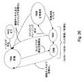
図26は、下で説明するディスプレイ状態図2600を図示している。状態2602では、電圧は検出されず、ディスプレイは、オフ状態へ進む。待機モード状態2604では、メインリンクレシーバ及び補助チャネルスレーブは、両方とも、電気的にアイドルとなり、補助チャネルスレーブポートの終端レジスタに渡る電圧降下が、所定の電圧についてモニタされる。所定の電圧が検出された場合、補助チャネルスレーブポートは、オンになってホットプラグイベントを示し、システムは表示状態2606へ移行し、そうでない場合、ディスプレイは待機状態2604にとどまる。状態2606(メインリンク初期化段階)において、ディスプレイが検出された場合、補助スレーブポートは、完全にオンとなり、トランスミッタは、レシーバリンク能力読み出しコマンドに応答し、ディスプレイ状態は2608に遷移し、そうでない場合には、所定の期間を超えて補助チャネルでの活動が存在しなければ、補助チャネルスレーブポートは、待機状態2604に入る。 FIG. 26 illustrates a display state diagram 2600 described below. In state 2602, no voltage is detected and the display proceeds to the off state. In standby mode state 2604, both the main link receiver and the auxiliary channel slave are electrically idle, and the voltage drop across the auxiliary channel slave port termination register is monitored for a predetermined voltage. If a predetermined voltage is detected, the auxiliary channel slave port is turned on to indicate a hot plug event, the system transitions to display state 2606, otherwise the display remains in standby state 2604. In state 2606 (main link initialization phase), if a display is detected, the auxiliary slave port is fully on, the transmitter responds to a receiver link capability read command, the display state transitions to 2608, otherwise In some cases, the auxiliary channel slave port enters a wait state 2604 if there is no activity on the auxiliary channel beyond a predetermined period of time.
トレーニング開始通知段階の間、ディスプレイは、トレーニングパターンを使用してイコライザを調整し、各段階の結果を更新することで、トランスミッタによるトレーニング始動に応答する。トレーニングが失敗した場合には、別のトレーニングセッションを待ち、トレーニングが成功した場合には、正常動作状態2610へ移行する。所定の時間(例えば、10ms)を超えて補助チャネル又は(トレーニングのための)メインリンクでの活動が存在しない場合、補助チャネルスレーブポートは、待機状態2604に設定される。 During the training start notification phase, the display responds to the training start by the transmitter by adjusting the equalizer using the training pattern and updating the results of each phase. If the training fails, another training session is waited, and if the training is successful, the normal operation state 2610 is entered. If there is no activity on the auxiliary channel or main link (for training) beyond a predetermined time (eg, 10 ms), the auxiliary channel slave port is set to a standby state 2604.
図27〜31は、クロスプラットフォームインタフェースの特定の実装を図示している。 Figures 27-31 illustrate specific implementations of the cross-platform interface.
図27は、本発明によるトランスミッタ2704を組み込んだオンボードグラフィックスエンジン2002を有するPCマザーボード200を図示している。トランスミッタ2704は、図1に図示したトランスミッタ102の特定の例であることに留意されたい。説明する実施形態において、トランスミッタ2704は、マザーボード2000にマウントされた(コネクタ2400の線に沿った)コネクタ2706に結合され、次にコネクタ2706は、ディスプレイデバイス2710を結合するツイストペアケーブル2710を経由して、ディスプレイデバイス2708に接続される。 FIG. 27 illustrates a
この技術で知られているように、PCI Express(カリフォルニア州サンタクララのIntel Corporationが開発)は、広帯域幅で低ピン数のシリアル相互接続技術であり、既存のPCIインフラとのソフトウェア互換性も維持する。この構成において、PCI Expressポートは、図示したマザーボードマウントコネクタを使用しても、ディスプレイデバイスを直接的に駆動できるクロスプラットフォームインタフェースの要件に準拠するように増強される。 As is known for this technology, PCI Express (developed by Intel Corporation, Santa Clara, Calif.) Is a high-bandwidth, low-pin-count serial interconnect technology that maintains software compatibility with existing PCI infrastructure. To do. In this configuration, the PCI Express port is augmented to comply with the requirements of a cross-platform interface that can directly drive the display device, even using the illustrated motherboard mount connector.
マザーボードにコネクタをマウントするのが実際的ではない状況において、信号は、PCI ExpressマザーボードのSDVOスロットを通じてルートを定め、図28に図示したような受動カードコネクタを使用して、PCの背面に伝えることができる。現世代のアドイングラフィックスカードと同様に、アドイングラフィックスカードは、図30に図示したようなオンボードグラフィックスエンジンに取って代わることができる。 In situations where it is not practical to mount the connector on the motherboard, the signal is routed through the SDVO slot on the PCI Express motherboard and passed to the back of the PC using a passive card connector as shown in FIG. Can do. Like current generation add-in graphics cards, add-in graphics cards can replace on-board graphics engines as illustrated in FIG.
ノートブックでの応用の場合、マザーボードグラフィックスエンジン上のトランスミッタにより、パネルを直接的に駆動する一体式レシーバ/TCONが、内部配線を通じて駆動される。最も費用効率に優れた実施では、レシーバ/TCONは、パネル上にマウントされ、これにより、相互接続線の数は、図31に図示したように八本又は十本に低減される。 For notebook applications, a transmitter on the motherboard graphics engine drives an integrated receiver / TCON that drives the panel directly through internal wiring. In the most cost effective implementation, the receiver / TCON is mounted on a panel, which reduces the number of interconnect lines to eight or ten as illustrated in FIG.
上の全ての例では、一体式トランスミッタを想定している。しかしながら、PCI及びPCI Express環境に、それぞれAGP又はSDVOスロットを通じて統合される、スタンドアロントランスミッタとしても、完全に実現可能である。スタンドアロントランスミッタは、グラフィックスハードウェア又はソフトウェアを全く変化させることなく、出力ストリームを可能にする。 All of the above examples assume an integral transmitter. However, it can also be fully implemented as a stand-alone transmitter integrated into the PCI and PCI Express environments through AGP or SDVO slots, respectively. Stand-alone transmitters allow output streams without any change in graphics hardware or software.
フローチャートの実施形態:
次に、本発明の方法について、本発明を可能にする特定のプロセスをそれぞれが説明する多数のフローチャートの観点から説明する。具体的には、図32〜36は、単独で或いは任意の組み合わせで使用される時に本発明の態様を説明する、多数の相互に関連するプロセスを表している。Flowchart embodiment:
The method of the present invention will now be described in terms of a number of flowcharts each describing a particular process that enables the present invention. Specifically, FIGS. 32-36 represent a number of interrelated processes that describe aspects of the present invention when used alone or in any combination.
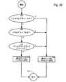
図32は、本発明の実施形態による、インタフェース100の動作モードを決定するプロセス3200を詳細に表すフローチャートを図示している。このプロセスにおいて、動作モードは、ビデオソース及びディスプレイデバイスが共にデジタルである場合、デジタルモードのみに設定されることになる。そうでない場合、動作モードは、アナログモードに設定されることになる。このコンテクストにおける「アナログモード」は、従来のVGAモードと、埋め込みアライメント信号及び双方向側波帯を備えた差動アナログビデオを有する拡張アナログモードとの両方を含むことに留意されたい。この拡張アナログモードについては、下で説明する。 FIG. 32 illustrates a flowchart detailing a process 3200 for determining an operating mode of the
ステップ3202において、ビデオソースは、ビデオソースがアナログ又はデジタルデータをサポートするかを判断するために問い合わせを受ける。ビデオソースがアナログデータのみをサポートする場合、結合デバイス100の動作モードは、アナログに設定され(ステップ3208)、プロセスは終了することになる(ステップ3212)。 In
ビデオソースがデジタルデータを出力できる場合、プロセスは、ステップ3206へ続く。ディスプレイデバイスは、次に、ディスプレイデバイスがデジタルデータを受領するように構成されているかを判断するために問い合わせを受ける。ディスプレイデバイスがアナログデータのみをサポートする場合、結合デバイス100の動作モードは、アナログに設定され(ステップ3208)、プロセスは終了することになる(ステップ3212)。そうでない場合、結合デバイス100の動作モードは、デジタルに設定される(ステップ3210)。例えば、プロセッサは、モードをデジタルに設定するために、結合デバイス内のスイッチを制御してよい。一般に、結合デバイスは、ビデオソース及びビデオシンクが対応するデジタルモードで動作する時のみ、完全デジタルモードで動作するように構成される。 If the video source can output digital data, the process continues to step 3206. The display device is then interrogated to determine if the display device is configured to receive digital data. If the display device supports only analog data, the operating mode of the
図33は、本発明の一部の態様による、リアルタイムビデオ画質チェックを提供するプロセス3300を詳細に表すフォーチャートを図示している。この例において、プロセス3300の全ての判定は、ディスプレイインタフェースに結合されたプロセッサにより行われる。 FIG. 33 illustrates a four-chart detailing a
ステップ3300において、ビデオ信号が、ビデオソースから受領される。次に、信号品質テストパターンが、受領ビデオ信号に関連するビデオソースによって提供される(ステップ3302)。ステップ3304において、品質テストパターンに基づいて、ビット誤り率が判定される。その後、ビット誤り率が閾値より大きいかについて判定される(ステップ3306)。ビット誤り率が閾値より大きくないと判定された場合には、ビデオフレームが更に存在するかどうかについて判定される(ステップ3314)。ビデオフレームが更に存在しないと判定された場合には、プロセスは、ステップ3300に戻る。そうでない場合、プロセスは終了する。 In
しかしながら、ステップ3306において、ビット誤り率が閾値より大きいと判定された場合、ビットレートが最小ビットレートより大きいかについての判定が行われる(ステップ3308)。ビットレートが最小ビットレートより大きい場合、ビットレートを低下させ(ステップ3310)、プロセスはステップ3306に戻る。ビットレートが最小ビットレートより大きくない場合は、モードをアナログモードに変更し(ステップ3312)、プロセスを終了する。 However, if it is determined in
図34は、本発明の実施形態による、リンク設定プロセス3400のフローチャートを図示している。プロセス3400は、3402において、ホットプラグ検出イベント通知の受領によって開始される。3404において、最大データレートと、レシーバに含まれる時間基準回復ユニット数と、利用可能なバッファサイズとを決定するために、関連する補助チャネルを経由して、メインリンクの問い合わせが行われる。次に、3406において、最大リンクデータレートが、トレーニングセッションを経由して検証され、3408において、データストリームソースは、ホットプラグイベントを通知される。3410において、ディスプレイの能力が、補助チャネルを経由して(例えば、EDIDを使用して)決定され、ディスプレイは、3412において、問い合わせに応答し、次に、3414において、メインリンクトレーニングセッションのための協働が生じる。 FIG. 34 illustrates a flowchart of a link setup process 3400 according to an embodiment of the present invention. Process 3400 begins at 3402 with receipt of a hot plug detection event notification. At 3404, the main link is queried via the associated auxiliary channel to determine the maximum data rate, the number of time base recovery units included in the receiver, and the available buffer size. Next, at 3406, the maximum link data rate is verified via the training session, and at 3408, the data stream source is notified of the hot plug event. At 3410, display capabilities are determined via an auxiliary channel (eg, using EDID), the display responds to the query at 3412, and then at 3414 for the main link training session. Collaboration occurs.
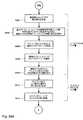
次に、3416において、ストリームソースは、補助チャネルを経由して、レシーバにストリーム属性を送信し、3418において、ストリームソースは、メインリンクが3420での要求データストリーム数をサポートできるかを更に通知される。3422において、様々なデータパケットが、関連するパケットヘッダを追加することで形成され、3424において、多数のソースストリームの多重化がスケジュールされる。3426において、リンク状態がOKかどうかについて、判定が行われる。リンク状態がOKではない場合、(複数の)ソースは、3428においてリンク障害イベントの通知を受け、そうでない場合、リンクデータストリームは、3430において様々なパケットヘッダに基づいて、ネイティブストリームに再構築される。3432において、再構築されたネイティブストリームは、ディスプレイデバイスに渡される。 Next, at 3416, the stream source sends the stream attribute to the receiver via the auxiliary channel, and at 3418 the stream source is further notified if the main link can support the requested number of data streams at 3420. The At 3422, various data packets are formed by adding associated packet headers, and at 3424, multiplexing of multiple source streams is scheduled. At 3426, a determination is made as to whether the link state is OK. If the link state is not OK, the source (s) are notified of a link failure event at 3428, otherwise the link data stream is reconstructed into a native stream at 3430 based on various packet headers. The At 3432, the reconstructed native stream is passed to the display device.
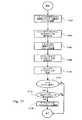
図35は、本発明の実施形態による、トレーニングセッションを実行するプロセス3500を詳細に表すフローチャートを図示している。トレーニングセッションプロセス3500は、図32において説明した動作3206の一実施であることに留意されたい。トレーニングセッションは、3502において、設定リンクレートにより、メインリンク上でトレーニングパターンをレシーバに送信することで開始される。通常のリンクトレーニングパターンは、本発明の実施形態による、通常のトレーニングパターンは、図11に図示される。例示のように、トレーニングセッション中、段階1は、最短のランレングスを表し、一方、段階2は、最長のものとなる。レシーバは、こうした二つの段階を使用して、イコライザを最適化する。段階3において、ビットロック及び文字ロックは、両方とも、リンク品質が妥当である限り達成される。3504において、レシーバは、関連するトレーニング状態をチェックし、トレーニング状態のチェックに基づいて、レシーバは、3506において、三段階のそれぞれとトランスミッタとについて、成功/失敗ビットを設定する。各段階において、レシーバは、成功のみが検出された時に次の段階に進み、3510において、レシーバが成功を検出しない場合、レシーバは、リンクレートを低減し、トレーニングセッションを繰り返す。メインリンクでは、3512において、成功が検出されたリンクレートでの準備が整う。 FIG. 35 illustrates a flowchart detailing a process 3500 for performing a training session according to an embodiment of the present invention. Note that the training session process 3500 is an implementation of the
図36は、本発明を実施するために利用されるコンピュータシステム3600を例示している。コンピュータシステム3600は、本発明の実施可能なグラフィックスシステムの例に過ぎない。コンピュータシステム3600は、中央処理装置(CPU)3610と、ランダムアクセスメモリ(RAM)3620と、読み出し専用メモリ(ROM)3625と、一つ以上の周辺機器3630と、グラフィックスコントローラ3660と、一次記憶デバイス3640及び3650と、デジタルディスプレイユニット3670とを含む。この技術でよく知られているように、ROMは、データ及び命令を単方向でCPU3610に転送する役割を果たし、一方、RAMは、通常、データ及び命令を双方向の形で転送するために使用される。CPU3610は、一般に、任意の数のプロセッサを含んでもよい。一次記憶デバイス3640及び3650は、両方とも、任意の適切なコンピュータ読取可能な媒体を含んでもよい。通常は大容量メモリデバイスである二次記憶媒体880も、双方向でCPU3610に結合され、追加的なデータ記憶容量を提供する。大容量メモリデバイス880は、コンピュータコード、データ、及びその他を含む、プログラムを格納するのに使用し得るコンピュータ可読媒体である。通常、大容量メモリデバイス880は、一次記録デバイス3640、3650よりも一般的に低速な、ハードディスク又はテープのような記憶媒体である。大容量メモリ記憶デバイス880は、磁気又は紙テープリーダ、或いは他の何らかの広く知られたデバイスの形態をとってもよい。大容量メモリデバイス880内で保持される情報は、適切である場合、標準的な形で、仮想メモリとしてRAM3620の一部に組み込んでもよいと理解される。 FIG. 36 illustrates a
CPU3610は、更に、ビデオモニタ、トラックボール、マウス、キーボード、マイクロフォン、タッチセンシティブディスプレイ、トランスデューサカードリーダ、磁気又は紙テープリーダ、タブレット、スタイラス、音声又は手書認識器、或いは、当然ながら、他のコンピュータ等、その他の広く知られた入力デバイスといったデバイスを一部として含んでもよい一つ以上の入出力デバイス890に結合される。最後に、CPU3610は、3695において一般的に図示したようなネットワーク接続を使用して、コンピュータ、或いはインターネットネットワーク又はイントラネットネットワーク等の電気通信ネットワークに、随意的に結合してもよい。こうしたネットワーク接続により、CPU3610は、上記の方法のステップを実行する過程で、ネットワークから情報を受領してよく、或いは、ネットワークに情報を出力してよいと考えられる。こうした情報は、CPU3610を使用して実行されるべき命令のシーケンスとして表現される場合が多く、例えば、搬送波内で具現化されるコンピュータデータ信号の形態で、ネットワークから受領され、ネットワークに出力されてよい。上記のデバイス及び材料は、コンピュータハードウェア及びソフトウェアに関わる当業者によく知られている。 The
グラフィックスコントローラ3660は、アナログ画像信号と対応する基準信号とを生成し、両方をデジタルディスプレイユニット3670に提供する。アナログ画像データは、例えば、CPU3610又は外部エンコード(図示なし)から受領したピクセルデータに基づいて生成できる。一実施形態において、アナログ画像データは、RGB形式で提供され、基準信号は、この技術で広く知られたVSYNC及びHSYNC信号を含む。しかしながら、本発明は、その他の形式のアナログ画像、データ、及び/又は基準信号により実施することも可能であると理解するべきである。例えば、アナログ画像データは、対応する時間基準信号を更に備えるビデオ信号データを含むことができる。 The
本発明のいくつかの実施形態のみを説明してきたが、本発明は、本発明の趣旨又は範囲から逸脱することなく他の多数の特定の形態で実施し得ると理解されるべきである。この説明は、制限的ではなく例示的なものと考えられるべきであり、本発明は、本明細書に記載した詳細に限定されず、付記する請求項の範囲内及び等価物の全範囲内で、変形し得る。 While only certain embodiments of the invention have been described, it should be understood that the invention can be embodied in many other specific forms without departing from the spirit or scope of the invention. This description is to be regarded as illustrative rather than restrictive, and the invention is not limited to the details described herein, but within the scope of the appended claims and the full scope of equivalents. Can be deformed.
以上、好適な実施形態の観点から本発明を説明してきたが、本発明の範囲内に含まれる変更、置換、及び等価物が存在する。また、本発明のプロセス及び装置の両方を実現する多数の代替方法が存在することに留意されたい。したがって、本発明は、本発明の本来の趣旨及び範囲内に入るこうした全ての変更、置換、及び等価物を含むものであると解釈されるべきである。 Although the invention has been described in terms of the preferred embodiments, there are alterations, substitutions, and equivalents that fall within the scope of the invention. It should also be noted that there are numerous alternative ways of implementing both the process and apparatus of the present invention. Accordingly, the present invention should be construed as including all such modifications, substitutions, and equivalents that fall within the true spirit and scope of the present invention.
Claims (13)
Translated fromJapaneseソースデバイスに接続され、ネイティブストリームレートに従ってソースパケットデータストリームを受領するように構成されたトランスミッタユニットと、
前記シンクデバイスに接続されたレシーバユニットと、
前記トランスミッタユニットと前記レシーバユニットを接続し、前記トランスミッタユニットと前記レシーバユニットとの間で前記ネイティブストリームレートから独立したリンクレートに従い前記ソースパケットデータストリームに基づいて多数のマルチメディアデータパケットから形成されるマルチメディアデータパケットストリームを転送するように構成されたリンクユニットと、
前記リンクユニットに接続され、前記データストリームのうちの選択されたものについて前記リンクユニットを介して転送するためにデータパケットをスケジュールするように構成されたデータパケットスケジューラと、
を備え、
各データストリームのデータパケットサイズは、関連する固定サイズを有し、前記固定サイズはデータストリームビットレートとリンクビットレートとの間の比に依存する、ディスプレイインタフェース。A packetized display interface configured to couple a multimedia source device to a multimedia sink device,
A transmitter unit connected to the source device and configured to receive a source packet data stream according to a native stream rate;
A receiver unit connected to the sink device;
The transmitter unit and the receiver unit are connected and formed from a number of multimedia data packets based on the source packet data stream according to a link rate independent of the native stream rate between the transmitter unit and the receiver unit. A link unit configured to transfer a multimedia data packet stream;
A data packet scheduler connected to the link unit and configured to schedule data packets for forwarding through the link unit for a selected one of the data streams;
With
The display interface, wherein the data packet size of each data stream has an associated fixed size, said fixed size being dependent on the ratio between the data stream bit rate and the link bit rate.
前記トランスミッタユニットから前記レシーバユニットへ前記マルチメディアデータパケットを伝送するように構成された単方向メインリンクと、
前記トランスミッタユニットと前記レシーバユニットとの間を双方向に情報を転送するように構成された双方向補助リンクと、を備える、請求項1記載のディスプレイインタフェース。The link unit further includes:
A unidirectional main link configured to transmit the multimedia data packet from the transmitter unit to the receiver unit;
The display interface of claim 1, comprising a bi-directional auxiliary link configured to transfer information bi-directionally between the transmitter unit and the receiver unit.
前記マルチメディアデータパケットストリームのうちの特定の一つとそれぞれ関連付けられた多数の仮想リンクを備え、
前記仮想リンクのそれぞれは、関連する仮想リンク帯域幅と仮想リンクレートとを有する、請求項2記載のディスプレイインタフェース。The main link unit further includes:
Comprising a number of virtual links each associated with a particular one of the multimedia data packet streams;
The display interface of claim 2, wherein each of the virtual links has an associated virtual link bandwidth and virtual link rate.
トランスミッタユニットが接続されたソースデバイスを提供するステップと、
レシーバユニットが接続されたシンクデバイスを提供するステップと、
前記トランスミッタユニットにより、ネイティブストリームレートに従ったソースデータストリームを受領するステップと、
リンクユニットを介して前記トランスミッタユニットと前記レシーバユニットとを接続するステップと、
多数のマルチメディアデータパケッから成るマルチメディアデータパケットストリームを形成するステップと、
前記トランスミッタユニットと前記レシーバユニットとの間のリンクレートに従って前記マルチメディアデータパケットストリームを転送するためのトランスポートスケジュールを生成するステップと、
を備え、
前記マルチメディアデータパケットのそれぞれは、前記リンクレートとデータストリームビットレートとに基づいた固定サイズである、方法。A method of connecting a multimedia source device to a multimedia sink device, comprising:
Providing a source device to which the transmitter unit is connected;
Providing a sink device with a receiver unit connected thereto;
Receiving a source data stream according to a native stream rate by the transmitter unit;
Connecting the transmitter unit and the receiver unit via a link unit;
Forming a multimedia data packet stream comprising a number of multimedia data packets;
Generating a transport schedule for transferring the multimedia data packet stream according to a link rate between the transmitter unit and the receiver unit;
With
Each of the multimedia data packets is a fixed size based on the link rate and data stream bit rate.
前記トランスミッタユニットと前記レシーバユニットとの間を双方向に情報を転送するように構成された双方向補助リンクを提供するステップと、を更に含む、請求項7記載の方法。Providing a unidirectional main link configured to transmit the multimedia data packet from the transmitter unit to the receiver unit;
8. The method of claim 7, further comprising providing a bi-directional auxiliary link configured to transfer information bi-directionally between the transmitter unit and the receiver unit.
前記マルチメディアデータパケットストリームのうちの特定の一つにそれぞれ関連付けられた多数の仮想リンクを備え、
前記仮想リンクのそれぞれは、関連する仮想リンク帯域幅と仮想リンクレートとを有する、請求項9記載の方法。The main link unit further includes:
Comprising a number of virtual links each associated with a particular one of the multimedia data packet streams;
The method of claim 9, wherein each of the virtual links has an associated virtual link bandwidth and virtual link rate.
前記データパケットソースから前記データパケットシンクへデータパケット属性を送信するステップと、
前記ソースから前記シンクへ送信されるべき多数のデータストリームのそれぞれについて、ストリームビットレートをデータリンクビットレートと比較するステップと、
前記比較に基づいて、前記データストリームのそれぞれのパケットサイズを固定パケットサイズに設定するステップと、
各データパケットの少なくとも一つを組み合わせるステップと、
組み合わせたデータパケットを前記ソースから前記シンクへ転送するステップと、
を含む方法。A method for scheduling the transfer of a large number of data packets between a data source and a data sink via a data link, comprising:
Transmitting data packet attributes from the data packet source to the data packet sink;
Comparing the stream bit rate with the data link bit rate for each of a number of data streams to be transmitted from the source to the sink;
Setting each packet size of the data stream to a fixed packet size based on the comparison;
Combining at least one of each data packet;
Transferring a combined data packet from the source to the sink;
Including methods.
前記データパケットソースから前記データパケットシンクへデータパケット属性を送信するコンピュータコードと、
前記ソースから前記シンクへ送信されるべき多数のデータストリームのそれぞれについて、ストリームビットレートをデータリンクビットレートと比較するコンピュータコードと、
前記比較に基づいて、前記データストリームのそれぞれのパケットサイズを固定パケットサイズに設定するコンピュータコードと、
各データパケットの少なくとも一つを組み合わせるコンピュータコードと、
組み合わせたデータパケットを前記ソースから前記シンクへ転送するコンピュータコードと、
前記コードを格納するコンピュータ読取可能な媒体と、
を備えるコンピュータプログラム製品。A computer program product that schedules the transfer of a large number of data packets between a data source and a data sink via a data link,
Computer code for transmitting data packet attributes from the data packet source to the data packet sink;
Computer code for comparing the stream bit rate with the data link bit rate for each of a number of data streams to be transmitted from the source to the sink;
Computer code for setting each packet size of the data stream to a fixed packet size based on the comparison;
Computer code combining at least one of each data packet;
Computer code for transferring a combined data packet from the source to the sink;
A computer readable medium for storing the code;
A computer program product comprising:
Applications Claiming Priority (3)
| Application Number | Priority Date | Filing Date | Title |
|---|---|---|---|
| US50406003P | 2003-09-18 | 2003-09-18 | |
| US55235204P | 2004-03-10 | 2004-03-10 | |
| US10/909,085US7487273B2 (en) | 2003-09-18 | 2004-07-29 | Data packet based stream transport scheduler wherein transport data link does not include a clock line |
Publications (2)
| Publication Number | Publication Date |
|---|---|
| JP2005173553Atrue JP2005173553A (en) | 2005-06-30 |
| JP2005173553A5 JP2005173553A5 (en) | 2007-11-01 |
Family
ID=34199000
Family Applications (1)
| Application Number | Title | Priority Date | Filing Date |
|---|---|---|---|
| JP2004271144AWithdrawnJP2005173553A (en) | 2003-09-18 | 2004-09-17 | Packet-type stream transport scheduler and method of using the same |
Country Status (7)
| Country | Link |
|---|---|
| US (1) | US7487273B2 (en) |
| EP (1) | EP1517295A3 (en) |
| JP (1) | JP2005173553A (en) |
| KR (1) | KR20050028869A (en) |
| CN (1) | CN1602001B (en) |
| SG (1) | SG110144A1 (en) |
| TW (1) | TWI353167B (en) |
Cited By (6)
| Publication number | Priority date | Publication date | Assignee | Title |
|---|---|---|---|---|
| JP2009116732A (en)* | 2007-11-08 | 2009-05-28 | Sony Corp | Information processor and information processing method |
| WO2009110561A1 (en)* | 2008-03-05 | 2009-09-11 | ソニー株式会社 | Transmission device and reception device |
| JP2010004510A (en)* | 2008-03-05 | 2010-01-07 | Sony Corp | Transmitting device and receiving device |
| JP2010539774A (en)* | 2007-09-14 | 2010-12-16 | ドゥー テクノロジーズ エフゼットシーオー | Method and system for processing images |
| JP2011515999A (en)* | 2008-03-27 | 2011-05-19 | シナーチップ カンパニー、リミテッド | Bidirectional digital interface for video and audio (DiiVA) |
| US9685785B2 (en) | 2008-12-11 | 2017-06-20 | Lattice Semiconductor Corporation | Power delivery over digital interaction interface for video and audio (DiiVA) |
Families Citing this family (83)
| Publication number | Priority date | Publication date | Assignee | Title |
|---|---|---|---|---|
| DE10252165A1 (en)* | 2002-11-09 | 2004-05-19 | Philips Intellectual Property & Standards Gmbh | Communications integrated circuit for implementation of send and receive functions of a network node, especially of a motor vehicle data bus node using the local interconnect network protocol, has an autonomous interface circuit |
| US7620062B2 (en)* | 2003-05-01 | 2009-11-17 | Genesis Microchips Inc. | Method of real time optimizing multimedia packet transmission rate |
| US20040218624A1 (en)* | 2003-05-01 | 2004-11-04 | Genesis Microchip Inc. | Packet based closed loop video display interface with periodic status checks |
| US7567592B2 (en)* | 2003-05-01 | 2009-07-28 | Genesis Microchip Inc. | Packet based video display interface enumeration method |
| US8068485B2 (en) | 2003-05-01 | 2011-11-29 | Genesis Microchip Inc. | Multimedia interface |
| US7068686B2 (en) | 2003-05-01 | 2006-06-27 | Genesis Microchip Inc. | Method and apparatus for efficient transmission of multimedia data packets |
| US8059673B2 (en)* | 2003-05-01 | 2011-11-15 | Genesis Microchip Inc. | Dynamic resource re-allocation in a packet based video display interface |
| US7424558B2 (en)* | 2003-05-01 | 2008-09-09 | Genesis Microchip Inc. | Method of adaptively connecting a video source and a video display |
| US7405719B2 (en)* | 2003-05-01 | 2008-07-29 | Genesis Microchip Inc. | Using packet transfer for driving LCD panel driver electronics |
| US20040221315A1 (en)* | 2003-05-01 | 2004-11-04 | Genesis Microchip Inc. | Video interface arranged to provide pixel data independent of a link character clock |
| US8204076B2 (en)* | 2003-05-01 | 2012-06-19 | Genesis Microchip Inc. | Compact packet based multimedia interface |
| US6992987B2 (en)* | 2003-05-01 | 2006-01-31 | Genesis Microchip Inc. | Enumeration method for the link clock rate and the pixel/audio clock rate |
| US7733915B2 (en)* | 2003-05-01 | 2010-06-08 | Genesis Microchip Inc. | Minimizing buffer requirements in a digital video system |
| US7839860B2 (en)* | 2003-05-01 | 2010-11-23 | Genesis Microchip Inc. | Packet based video display interface |
| US7088741B2 (en) | 2003-05-01 | 2006-08-08 | Genesis Microchip Inc. | Using an auxilary channel for video monitor training |
| US20040221312A1 (en)* | 2003-05-01 | 2004-11-04 | Genesis Microchip Inc. | Techniques for reducing multimedia data packet overhead |
| US20040218599A1 (en)* | 2003-05-01 | 2004-11-04 | Genesis Microchip Inc. | Packet based video display interface and methods of use thereof |
| KR100698620B1 (en)* | 2003-06-16 | 2007-03-21 | 삼성전자주식회사 | Digital Transmission / Reception System with Robust Error Correction Coding Device and Its Error Correction Coding / Correcting Method |
| US7487273B2 (en) | 2003-09-18 | 2009-02-03 | Genesis Microchip Inc. | Data packet based stream transport scheduler wherein transport data link does not include a clock line |
| US7800623B2 (en)* | 2003-09-18 | 2010-09-21 | Genesis Microchip Inc. | Bypassing pixel clock generation and CRTC circuits in a graphics controller chip |
| US7613300B2 (en)* | 2003-09-26 | 2009-11-03 | Genesis Microchip Inc. | Content-protected digital link over a single signal line |
| US7634090B2 (en)* | 2003-09-26 | 2009-12-15 | Genesis Microchip Inc. | Packet based high definition high-bandwidth digital content protection |
| US7840714B2 (en)* | 2003-12-24 | 2010-11-23 | Intel Corporation | Mapping SDVO functions from PCI express interface |
| JP2005328280A (en)* | 2004-05-13 | 2005-11-24 | Canon Inc | Data processing device |
| US7152136B1 (en)* | 2004-08-03 | 2006-12-19 | Altera Corporation | Implementation of PCI express |
| US7257655B1 (en) | 2004-10-13 | 2007-08-14 | Altera Corporation | Embedded PCI-Express implementation |
| IES20040777A2 (en)* | 2004-11-22 | 2006-04-19 | Pendula Ltd | Protection of electronic data |
| CN102394049B (en) | 2005-05-02 | 2015-04-15 | 株式会社半导体能源研究所 | Driving method of display device |
| US8059109B2 (en) | 2005-05-20 | 2011-11-15 | Semiconductor Energy Laboratory Co., Ltd. | Display device and electronic apparatus |
| EP1724751B1 (en)* | 2005-05-20 | 2013-04-10 | Semiconductor Energy Laboratory Co., Ltd. | Liquid crystal display device and electronic apparatus |
| US7536489B2 (en) | 2005-08-30 | 2009-05-19 | Ricoh Company Limited | Information processing system for determining payload size based on packet-to-payload size ratio |
| US8433173B2 (en)* | 2005-09-29 | 2013-04-30 | Nikon Corporation | Portable media player system |
| US7613848B2 (en)* | 2006-06-13 | 2009-11-03 | International Business Machines Corporation | Dynamic stabilization for a stream processing system |
| DE602007008582D1 (en)* | 2006-09-06 | 2010-09-30 | Thomson Licensing | DEVICE FOR PROCESSING A CURRENT OF DATA WORDS |
| US20080089321A1 (en)* | 2006-10-17 | 2008-04-17 | Cypress Semiconductor Corp. | Electronic Switch Architecture and Method having Multiple Ports Coupled by a Single Data Link for Transferring Different Data Types Across the Link |
| US7761469B2 (en)* | 2006-11-29 | 2010-07-20 | Red Hat, Inc. | Streamed attributes |
| TWI360803B (en)* | 2007-01-26 | 2012-03-21 | Realtek Semiconductor Corp | Apparatus and method for reducing output speed of |
| US7956856B2 (en)* | 2007-02-15 | 2011-06-07 | Parade Technologies, Ltd. | Method and apparatus of generating or reconstructing display streams in video interface systems |
| US8248960B2 (en) | 2007-05-01 | 2012-08-21 | Sharp Kabushiki Kaisha | Data transmission with dynamic modulation scheme and/or transfer rate |
| US7929525B2 (en)* | 2007-06-28 | 2011-04-19 | Dell Products L.P. | System and method for adding transport layer to uncompressed visual information packets |
| US20090094658A1 (en)* | 2007-10-09 | 2009-04-09 | Genesis Microchip Inc. | Methods and systems for driving multiple displays |
| US20090219932A1 (en)* | 2008-02-04 | 2009-09-03 | Stmicroelectronics, Inc. | Multi-stream data transport and methods of use |
| US20090262667A1 (en)* | 2008-04-21 | 2009-10-22 | Stmicroelectronics, Inc. | System and method for enabling topology mapping and communication between devices in a network |
| WO2009147839A1 (en)* | 2008-06-03 | 2009-12-10 | キヤノン株式会社 | Communication device and conversion adapter |
| US20100183004A1 (en)* | 2009-01-16 | 2010-07-22 | Stmicroelectronics, Inc. | System and method for dual mode communication between devices in a network |
| US8156238B2 (en) | 2009-05-13 | 2012-04-10 | Stmicroelectronics, Inc. | Wireless multimedia transport method and apparatus |
| US8760461B2 (en) | 2009-05-13 | 2014-06-24 | Stmicroelectronics, Inc. | Device, system, and method for wide gamut color space support |
| US8860888B2 (en)* | 2009-05-13 | 2014-10-14 | Stmicroelectronics, Inc. | Method and apparatus for power saving during video blanking periods |
| US8429440B2 (en)* | 2009-05-13 | 2013-04-23 | Stmicroelectronics, Inc. | Flat panel display driver method and system |
| US8291207B2 (en)* | 2009-05-18 | 2012-10-16 | Stmicroelectronics, Inc. | Frequency and symbol locking using signal generated clock frequency and symbol identification |
| US8582452B2 (en) | 2009-05-18 | 2013-11-12 | Stmicroelectronics, Inc. | Data link configuration by a receiver in the absence of link training data |
| US8468285B2 (en)* | 2009-05-18 | 2013-06-18 | Stmicroelectronics, Inc. | Operation of video source and sink with toggled hot plug detection |
| US8370554B2 (en)* | 2009-05-18 | 2013-02-05 | Stmicroelectronics, Inc. | Operation of video source and sink with hot plug detection not asserted |
| US8941693B2 (en)* | 2009-09-03 | 2015-01-27 | Ati Technologies Ulc | Method and apparatus for providing reduced power usage of a display interface |
| US8793410B2 (en)* | 2009-12-14 | 2014-07-29 | Stmicroelectronics, Inc. | Data rate throttling in an internal packet-based interface |
| CN102130819A (en)* | 2010-01-13 | 2011-07-20 | 中国移动通信集团公司 | Flow service scheduling method and device |
| US20110273805A1 (en)* | 2010-05-06 | 2011-11-10 | Nguyen Don J | Hdmi cable connect apparatus and method |
| US8671234B2 (en) | 2010-05-27 | 2014-03-11 | Stmicroelectronics, Inc. | Level shifting cable adaptor and chip system for use with dual-mode multi-media device |
| FR2969336B1 (en)* | 2010-12-17 | 2013-01-04 | Sagem Defense Securite | MULTIPLE ETHERNET CONNECTION DEVICE WITH COMPUTER UNIT AND COMPUTER UNIT ASSEMBLY AND RELATED EQUIPMENT TOGETHER |
| US8750176B2 (en) | 2010-12-22 | 2014-06-10 | Apple Inc. | Methods and apparatus for the intelligent association of control symbols |
| JP5771986B2 (en)* | 2010-12-28 | 2015-09-02 | ソニー株式会社 | Electronic device, electronic device control method, and electronic device system |
| US9053673B2 (en) | 2011-03-23 | 2015-06-09 | Parade Technologies, Ltd. | Scalable intra-panel interface |
| US8681170B2 (en)* | 2011-05-05 | 2014-03-25 | Ati Technologies Ulc | Apparatus and method for multi-streaming for more than three pixel component values |
| US9106770B2 (en)* | 2011-06-21 | 2015-08-11 | Parade Technologies, Ltd. | Column drivers with embedded high-speed video interface timing controller |
| US9311840B2 (en)* | 2011-08-26 | 2016-04-12 | Himax Technologies Limited | Display and operating method thereof |
| US8705639B2 (en)* | 2011-10-19 | 2014-04-22 | Comcast Cable Communications, Llc | Signal monitoring platform |
| US9838226B2 (en) | 2012-01-27 | 2017-12-05 | Apple Inc. | Methods and apparatus for the intelligent scrambling of control symbols |
| US8897398B2 (en) | 2012-01-27 | 2014-11-25 | Apple Inc. | Methods and apparatus for error rate estimation |
| TWI482472B (en)* | 2012-04-06 | 2015-04-21 | Realtek Semiconductor Corp | Multimedia transmission server, multimedia transmission method, and relevant computer program product |
| US20140098852A1 (en)* | 2012-10-05 | 2014-04-10 | Samsung Display Co., Ltd. | Compression bandwidth overflow management using auxiliary control channel |
| US8988416B2 (en) | 2012-12-14 | 2015-03-24 | Parade Technologies, Ltd. | Power reduction technique for digital display panel with point to point intra panel interface |
| US9450790B2 (en) | 2013-01-31 | 2016-09-20 | Apple Inc. | Methods and apparatus for enabling and disabling scrambling of control symbols |
| US8917194B2 (en) | 2013-03-15 | 2014-12-23 | Apple, Inc. | Methods and apparatus for context based line coding |
| US9210010B2 (en) | 2013-03-15 | 2015-12-08 | Apple, Inc. | Methods and apparatus for scrambling symbols over multi-lane serial interfaces |
| US9197680B2 (en)* | 2013-05-23 | 2015-11-24 | Qualcomm Incorporated | Establishing and controlling audio and voice back channels of a Wi-Fi display connection |
| US9578141B2 (en)* | 2013-11-03 | 2017-02-21 | Ixia | Packet flow modification |
| CN105791991B (en)* | 2014-12-22 | 2018-07-17 | Tcl集团股份有限公司 | Television system and its implementation based on Firefox OS platforms |
| CN104536929A (en)* | 2015-01-14 | 2015-04-22 | 浪潮(北京)电子信息产业有限公司 | Physical layer initialization method and client terminals |
| CN111130782B (en)* | 2020-03-31 | 2020-08-28 | 北京中创为南京量子通信技术有限公司 | Quantum key distribution networking method and system |
| US11082557B1 (en)* | 2020-03-31 | 2021-08-03 | T-Mobile Usa, Inc. | Announcement or advertisement in text or video format for real time text or video calls |
| KR20210133668A (en)* | 2020-04-29 | 2021-11-08 | 주식회사 엘엑스세미콘 | Data processing device, data driving device and system for driving display device |
| US12231529B2 (en)* | 2022-03-28 | 2025-02-18 | Avago Technologies International Sales Pte. Limited | Time-sensitive multimedia endpoint interface bridging through ethernet transport |
| CN120359771A (en)* | 2023-09-28 | 2025-07-22 | 深圳引望智能技术有限公司 | Data transmission method and device |
Family Cites Families (118)
| Publication number | Priority date | Publication date | Assignee | Title |
|---|---|---|---|---|
| US4796203A (en) | 1986-08-26 | 1989-01-03 | Kabushiki Kaisha Toshiba | High resolution monitor interface and related interfacing method |
| DE68924737T2 (en) | 1988-08-09 | 1996-05-02 | Seiko Epson Corp | Display signal generator. |
| JPH02226416A (en) | 1989-02-28 | 1990-09-10 | Toshiba Corp | Color LCD display control device |
| KR910006834A (en) | 1989-09-29 | 1991-04-30 | 아오이 죠이치 | Display control device which can change the brightness by the condition of power circuit |
| JPH03153299A (en) | 1989-11-10 | 1991-07-01 | Pfu Ltd | Image processor |
| JPH04328919A (en)* | 1991-04-26 | 1992-11-17 | Fujitsu Ltd | Radio paging signaling system |
| US5926155A (en) | 1993-02-02 | 1999-07-20 | Hitachi, Ltd. | Digital video display system |
| US5838875A (en) | 1993-02-05 | 1998-11-17 | Goldstar Co., Ltd. | Apparatus and method for discriminating between analog and digital video signals in high definition video cassette recorder |
| WO1995000917A1 (en) | 1993-06-21 | 1995-01-05 | Multimedia Design Corporation | Integrated multimedia information management system |
| US5821918A (en) | 1993-07-29 | 1998-10-13 | S3 Incorporated | Video processing apparatus, systems and methods |
| US5481542A (en) | 1993-11-10 | 1996-01-02 | Scientific-Atlanta, Inc. | Interactive information services control system |
| US5739803A (en) | 1994-01-24 | 1998-04-14 | Arithmos, Inc. | Electronic system for driving liquid crystal displays |
| DE69509420T2 (en) | 1994-01-28 | 1999-12-16 | Sun Microsystems, Inc. | Interface for a flat display in a high-resolution graphic computer system |
| FI97928C (en) | 1994-03-21 | 1997-03-10 | Nokia Technology Gmbh | Method of encrypting a television transmission transmitted in digital form |
| FI95756C (en) | 1994-03-21 | 1996-03-11 | Nokia Technology Gmbh | Procedure for encryption and decryption of a bit stream containing digital information |
| US5615376A (en) | 1994-08-03 | 1997-03-25 | Neomagic Corp. | Clock management for power reduction in a video display sub-system |
| US5541919A (en) | 1994-12-19 | 1996-07-30 | Motorola, Inc. | Multimedia multiplexing device and method using dynamic packet segmentation |
| US5953350A (en) | 1995-03-13 | 1999-09-14 | Selsius Systems, Inc. | Multimedia client for multimedia/hybrid network |
| US5745837A (en) | 1995-08-25 | 1998-04-28 | Terayon Corporation | Apparatus and method for digital data transmission over a CATV system using an ATM transport protocol and SCDMA |
| US5805173A (en) | 1995-10-02 | 1998-09-08 | Brooktree Corporation | System and method for capturing and transferring selected portions of a video stream in a computer system |
| US5835498A (en) | 1995-10-05 | 1998-11-10 | Silicon Image, Inc. | System and method for sending multiple data signals over a serial link |
| GB2309872A (en) | 1996-02-05 | 1997-08-06 | Ibm | Digital display apparatus |
| US5940137A (en) | 1996-03-01 | 1999-08-17 | Trw Inc. | Symbol timing generation and recovery for data transmission in an analog video signal |
| US5790083A (en) | 1996-04-10 | 1998-08-04 | Neomagic Corp. | Programmable burst of line-clock pulses during vertical retrace to reduce flicker and charge build-up on passive LCD display panels during simultaneous LCD and CRT display |
| US6154225A (en) | 1996-10-11 | 2000-11-28 | Silicon Motion, Inc. | Virtual refresh™ architecture for a video-graphics controller |
| JPH10145309A (en) | 1996-11-05 | 1998-05-29 | Kokusai Electric Co Ltd | Data transmission system |
| JP3434653B2 (en) | 1996-12-05 | 2003-08-11 | 富士通株式会社 | Method and apparatus for storing and transmitting multimedia data |
| US5909465A (en) | 1996-12-05 | 1999-06-01 | Ericsson Inc. | Method and apparatus for bidirectional demodulation of digitally modulated signals |
| US6038000A (en) | 1997-05-28 | 2000-03-14 | Sarnoff Corporation | Information stream syntax for indicating the presence of a splice point |
| US6542610B2 (en) | 1997-01-30 | 2003-04-01 | Intel Corporation | Content protection for digital transmission systems |
| EP0960509B1 (en) | 1997-02-17 | 2005-12-07 | COMMUNICATION & CONTROL ELECTRONICS LIMITED | Local communication system |
| US5949437A (en) | 1997-02-19 | 1999-09-07 | Appian Graphics Corp. | Dual video output board with a shared memory interface |
| US6104414A (en) | 1997-03-12 | 2000-08-15 | Cybex Computer Products Corporation | Video distribution hub |
| US6151632A (en) | 1997-03-14 | 2000-11-21 | Microsoft Corporation | Method and apparatus for distributed transmission of real-time multimedia information |
| US5918002A (en) | 1997-03-14 | 1999-06-29 | Microsoft Corporation | Selective retransmission for efficient and reliable streaming of multimedia packets in a computer network |
| JP3385301B2 (en) | 1997-04-23 | 2003-03-10 | シャープ株式会社 | Data signal line drive circuit and image display device |
| US6020901A (en) | 1997-06-30 | 2000-02-01 | Sun Microsystems, Inc. | Fast frame buffer system architecture for video display system |
| US5852630A (en) | 1997-07-17 | 1998-12-22 | Globespan Semiconductor, Inc. | Method and apparatus for a RADSL transceiver warm start activation procedure with precoding |
| GB2329741A (en) | 1997-09-29 | 1999-03-31 | Holtek Microelectronics Inc | Liquid crystal display driver |
| JPH11175045A (en) | 1997-12-16 | 1999-07-02 | Matsushita Joho System Kk | Multiscreen video display controller and its control method |
| US6353594B1 (en) | 1998-03-04 | 2002-03-05 | Alcatel Canada Inc. | Semi-permanent virtual paths for carrying virtual channels |
| US6249319B1 (en) | 1998-03-30 | 2001-06-19 | International Business Machines Corporation | Method and apparatus for finding a correct synchronization point within a data stream |
| US6356260B1 (en) | 1998-04-10 | 2002-03-12 | National Semiconductor Corporation | Method for reducing power and electromagnetic interference in conveying video data |
| AU4422799A (en) | 1998-06-04 | 1999-12-20 | Silicon Image, Inc. | Display module driving system and digital to analog converter for driving display |
| US6593937B2 (en) | 1998-06-18 | 2003-07-15 | Sony Corporation | Method of and apparatus for handling high bandwidth on-screen-display graphics data over a distributed IEEE 1394 network utilizing an isochronous data transmission format |
| US6326961B1 (en) | 1998-09-30 | 2001-12-04 | Ctx Opto-Electronics Corp. | Automatic detection method for tuning the frequency and phase of display and apparatus using the method |
| AU9686898A (en) | 1998-10-06 | 2000-04-26 | Huey-Shiang Chen | A method for just-in-time retrieval of multimedia files over computer networks by transmitting data packets at transmission rate determined frame size |
| US6661422B1 (en) | 1998-11-09 | 2003-12-09 | Broadcom Corporation | Video and graphics system with MPEG specific data transfer commands |
| US6697376B1 (en) | 1998-11-20 | 2004-02-24 | Diva Systems Corporation | Logical node identification in an information transmission network |
| JP3768712B2 (en) | 1999-02-09 | 2006-04-19 | キヤノン株式会社 | Stirring means, developing device, and process cartridge |
| US6223089B1 (en) | 1999-03-15 | 2001-04-24 | Raylar Design, Inc. | Method and apparatus for controlling computers remotely |
| US6446130B1 (en) | 1999-03-16 | 2002-09-03 | Interactive Digital Systems | Multimedia delivery system |
| JP3816689B2 (en) | 1999-03-31 | 2006-08-30 | 株式会社東芝 | Information distribution apparatus, information reception apparatus, and communication method |
| US6765931B1 (en) | 1999-04-13 | 2004-07-20 | Broadcom Corporation | Gateway with voice |
| EP1069721B1 (en) | 1999-07-12 | 2004-01-02 | International Business Machines Corporation | Apparatus and method for setting a data rate in a wireless communication system |
| JP2001036900A (en) | 1999-07-22 | 2001-02-09 | Matsushita Electric Ind Co Ltd | Optical transmission device, its optical transmission method, transmission format, optical transmission element, projection display device, video display device, liquid crystal display device, and driving method thereof |
| US6598161B1 (en) | 1999-08-09 | 2003-07-22 | International Business Machines Corporation | Methods, systems and computer program products for multi-level encryption |
| US6477252B1 (en) | 1999-08-29 | 2002-11-05 | Intel Corporation | Digital video content transmission ciphering and deciphering method and apparatus |
| US6614800B1 (en) | 1999-09-02 | 2003-09-02 | International Business Machines Corporation | Method and system for virtual private network administration channels |
| US6608828B1 (en) | 1999-09-15 | 2003-08-19 | Ericsson Inc. | Methods and systems for decoding headers that are repeatedly transmitted and received along with data on a radio channel |
| US6633288B2 (en) | 1999-09-15 | 2003-10-14 | Sage, Inc. | Pixel clock PLL frequency and phase optimization in sampling of video signals for high quality image display |
| US6779037B1 (en) | 1999-09-28 | 2004-08-17 | Levan Roberto Djaparidze | Method of obtaining optimum use of a shared transmission medium for multimedia traffic |
| JP3950926B2 (en) | 1999-11-30 | 2007-08-01 | エーユー オプトロニクス コーポレイション | Image display method, host device, image display device, and display interface |
| JP2001218082A (en) | 2000-02-04 | 2001-08-10 | Sony Corp | Method for improving image quality of video interface and video interface circuit device |
| JP3349490B2 (en) | 2000-02-14 | 2002-11-25 | インターナショナル・ビジネス・マシーンズ・コーポレーション | Image display method, image display system, host device, image display device, and display interface |
| JP4639420B2 (en) | 2000-03-08 | 2011-02-23 | ソニー株式会社 | Signal transmission apparatus and signal transmission method |
| KR100694034B1 (en) | 2000-05-13 | 2007-03-12 | 삼성전자주식회사 | Data rate automatic detection device |
| JP2002049363A (en) | 2000-05-24 | 2002-02-15 | Sharp Corp | Image display system |
| AU2001294142A1 (en) | 2000-09-20 | 2002-04-02 | Main.Net Communication Ltd. | Multimedia communications over power lines |
| US20020075902A1 (en) | 2000-09-22 | 2002-06-20 | Abbas Syed Aun | Optimum overhead framing techniques for ADSL DMT modems |
| EP1348289B1 (en) | 2000-10-11 | 2006-04-05 | Broadcom Corporation | Cable modem system and method for supporting extended protocols |
| KR100349205B1 (en) | 2000-11-17 | 2002-08-21 | 삼성전자 주식회사 | An apparatus for detecting a DVI connector in a digital video signal display system |
| US6820614B2 (en) | 2000-12-02 | 2004-11-23 | The Bonutti 2003 Trust -A | Tracheal intubination |
| CA2327898A1 (en) | 2000-12-08 | 2002-06-08 | Alcatel Canada Inc. | System and method for establishing a communication path associated with an mpls implementation on an atm platform |
| KR100467643B1 (en) | 2000-12-28 | 2005-01-24 | 엘지전자 주식회사 | Method for multimedia data transmission in wireless LAN |
| US20020163598A1 (en) | 2001-01-24 | 2002-11-07 | Christopher Pasqualino | Digital visual interface supporting transport of audio and auxiliary data |
| US7161998B2 (en) | 2001-01-24 | 2007-01-09 | Broadcom Corporation | Digital phase locked loop for regenerating the clock of an embedded signal |
| US6934389B2 (en) | 2001-03-02 | 2005-08-23 | Ati International Srl | Method and apparatus for providing bus-encrypted copy protection key to an unsecured bus |
| TW518844B (en) | 2001-03-21 | 2003-01-21 | Ind Tech Res Inst | Transmission method of multimedia data packet in network system |
| US20020149617A1 (en) | 2001-03-30 | 2002-10-17 | Becker David F. | Remote collaboration technology design and methodology |
| JP3781980B2 (en) | 2001-04-09 | 2006-06-07 | Necディスプレイソリューションズ株式会社 | Data transfer system |
| US7194009B2 (en) | 2001-04-14 | 2007-03-20 | John Wai Tsang Eng | Full-service broadband cable modem system |
| US6970481B2 (en) | 2001-04-17 | 2005-11-29 | Microsoft Corporation | Methods and systems for distributing multimedia data over heterogeneous networks |
| JP3744819B2 (en) | 2001-05-24 | 2006-02-15 | セイコーエプソン株式会社 | Signal driving circuit, display device, electro-optical device, and signal driving method |
| US7257163B2 (en) | 2001-09-12 | 2007-08-14 | Silicon Image, Inc. | Method and system for reducing inter-symbol interference effects in transmission over a serial link with mapping of each word in a cluster of received words to a single transmitted word |
| JP4011320B2 (en) | 2001-10-01 | 2007-11-21 | 株式会社半導体エネルギー研究所 | Display device and electronic apparatus using the same |
| US20030076282A1 (en) | 2001-10-19 | 2003-04-24 | Semiconductor Energy Laboratory Co., Ltd. | Display device and method for driving the same |
| US7589737B2 (en) | 2001-10-31 | 2009-09-15 | Hewlett-Packard Development Company, L.P. | System and method for communicating graphics image data over a communication network |
| GB2383240B (en) | 2001-12-17 | 2005-02-16 | Micron Technology Inc | DVi link with parallel test data |
| US7106757B2 (en) | 2001-12-19 | 2006-09-12 | Intel Corporation | System and method for streaming multimedia over packet networks |
| JP3778079B2 (en)* | 2001-12-20 | 2006-05-24 | 株式会社日立製作所 | Display device |
| US7088398B1 (en) | 2001-12-24 | 2006-08-08 | Silicon Image, Inc. | Method and apparatus for regenerating a clock for auxiliary data transmitted over a serial link with video data |
| US7308059B2 (en) | 2002-02-06 | 2007-12-11 | Broadcom Corporation | Synchronization of data links in a multiple link receiver |
| US7120203B2 (en) | 2002-02-12 | 2006-10-10 | Broadcom Corporation | Dual link DVI transmitter serviced by single Phase Locked Loop |
| JP2003241724A (en) | 2002-02-15 | 2003-08-29 | Rohm Co Ltd | Display monitor device |
| US7161557B2 (en) | 2002-04-08 | 2007-01-09 | Clearcube Technology, Inc. | Selectively updating a display in a multi-display system |
| US7283566B2 (en) | 2002-06-14 | 2007-10-16 | Silicon Image, Inc. | Method and circuit for generating time stamp data from an embedded-clock audio data stream and a video clock |
| US7634675B2 (en) | 2002-09-05 | 2009-12-15 | Gateway, Inc. | Monitor power management |
| US7075987B2 (en) | 2002-09-23 | 2006-07-11 | Intel Corporation | Adaptive video bit-rate control |
| US7802049B2 (en) | 2002-10-30 | 2010-09-21 | Intel Corporation | Links having flexible lane allocation |
| US7203853B2 (en) | 2002-11-22 | 2007-04-10 | Intel Corporation | Apparatus and method for low latency power management on a serial data link |
| US7555017B2 (en)* | 2002-12-17 | 2009-06-30 | Tls Corporation | Low latency digital audio over packet switched networks |
| US7197680B2 (en) | 2003-04-17 | 2007-03-27 | Arm Limited | Communication interface for diagnostic circuits of an integrated circuit |
| US7424558B2 (en) | 2003-05-01 | 2008-09-09 | Genesis Microchip Inc. | Method of adaptively connecting a video source and a video display |
| US7733915B2 (en) | 2003-05-01 | 2010-06-08 | Genesis Microchip Inc. | Minimizing buffer requirements in a digital video system |
| US7405719B2 (en) | 2003-05-01 | 2008-07-29 | Genesis Microchip Inc. | Using packet transfer for driving LCD panel driver electronics |
| US7088741B2 (en) | 2003-05-01 | 2006-08-08 | Genesis Microchip Inc. | Using an auxilary channel for video monitor training |
| US20040218599A1 (en) | 2003-05-01 | 2004-11-04 | Genesis Microchip Inc. | Packet based video display interface and methods of use thereof |
| US7068686B2 (en)* | 2003-05-01 | 2006-06-27 | Genesis Microchip Inc. | Method and apparatus for efficient transmission of multimedia data packets |
| US6992987B2 (en) | 2003-05-01 | 2006-01-31 | Genesis Microchip Inc. | Enumeration method for the link clock rate and the pixel/audio clock rate |
| US7620062B2 (en) | 2003-05-01 | 2009-11-17 | Genesis Microchips Inc. | Method of real time optimizing multimedia packet transmission rate |
| US20040221312A1 (en) | 2003-05-01 | 2004-11-04 | Genesis Microchip Inc. | Techniques for reducing multimedia data packet overhead |
| US20040221315A1 (en) | 2003-05-01 | 2004-11-04 | Genesis Microchip Inc. | Video interface arranged to provide pixel data independent of a link character clock |
| US20040218624A1 (en) | 2003-05-01 | 2004-11-04 | Genesis Microchip Inc. | Packet based closed loop video display interface with periodic status checks |
| US7296204B2 (en) | 2003-05-30 | 2007-11-13 | Wegener Communications, Inc. | Error correction apparatus and method |
| US7487273B2 (en) | 2003-09-18 | 2009-02-03 | Genesis Microchip Inc. | Data packet based stream transport scheduler wherein transport data link does not include a clock line |
| US7800623B2 (en) | 2003-09-18 | 2010-09-21 | Genesis Microchip Inc. | Bypassing pixel clock generation and CRTC circuits in a graphics controller chip |
| US7634090B2 (en) | 2003-09-26 | 2009-12-15 | Genesis Microchip Inc. | Packet based high definition high-bandwidth digital content protection |
- 2004
- 2004-07-29USUS10/909,085patent/US7487273B2/enactiveActive
- 2004-09-16EPEP04255611Apatent/EP1517295A3/ennot_activeWithdrawn
- 2004-09-17TWTW093128282Apatent/TWI353167B/ennot_activeIP Right Cessation
- 2004-09-17CNCN2004100874609Apatent/CN1602001B/ennot_activeExpired - Lifetime
- 2004-09-17SGSG200405115Apatent/SG110144A1/enunknown
- 2004-09-17KRKR1020040074690Apatent/KR20050028869A/ennot_activeWithdrawn
- 2004-09-17JPJP2004271144Apatent/JP2005173553A/ennot_activeWithdrawn
Cited By (11)
| Publication number | Priority date | Publication date | Assignee | Title |
|---|---|---|---|---|
| JP2010539774A (en)* | 2007-09-14 | 2010-12-16 | ドゥー テクノロジーズ エフゼットシーオー | Method and system for processing images |
| JP2009116732A (en)* | 2007-11-08 | 2009-05-28 | Sony Corp | Information processor and information processing method |
| WO2009110561A1 (en)* | 2008-03-05 | 2009-09-11 | ソニー株式会社 | Transmission device and reception device |
| JP2010004510A (en)* | 2008-03-05 | 2010-01-07 | Sony Corp | Transmitting device and receiving device |
| US8898727B2 (en) | 2008-03-05 | 2014-11-25 | Sony Corporation | Transmission device and reception device |
| US9154831B2 (en) | 2008-03-05 | 2015-10-06 | Sony Corporation | Transmission device and reception device |
| US9525908B2 (en) | 2008-03-05 | 2016-12-20 | Sony Corporation | Transmission device and reception device |
| US9900653B2 (en) | 2008-03-05 | 2018-02-20 | Sony Corporation | Transmission device and reception device |
| JP2011515999A (en)* | 2008-03-27 | 2011-05-19 | シナーチップ カンパニー、リミテッド | Bidirectional digital interface for video and audio (DiiVA) |
| US9030976B2 (en) | 2008-03-27 | 2015-05-12 | Silicon Image, Inc. | Bi-directional digital interface for video and audio (DIVA) |
| US9685785B2 (en) | 2008-12-11 | 2017-06-20 | Lattice Semiconductor Corporation | Power delivery over digital interaction interface for video and audio (DiiVA) |
Also Published As
| Publication number | Publication date |
|---|---|
| US20050066085A1 (en) | 2005-03-24 |
| KR20050028869A (en) | 2005-03-23 |
| TWI353167B (en) | 2011-11-21 |
| CN1602001B (en) | 2010-09-08 |
| EP1517295A2 (en) | 2005-03-23 |
| US7487273B2 (en) | 2009-02-03 |
| CN1602001A (en) | 2005-03-30 |
| SG110144A1 (en) | 2005-04-28 |
| EP1517295A3 (en) | 2006-03-15 |
| TW200520542A (en) | 2005-06-16 |
Similar Documents
| Publication | Publication Date | Title |
|---|---|---|
| CN1602001B (en) | Packet-based data stream transmission scheduling device and method for applying the device | |
| US7424558B2 (en) | Method of adaptively connecting a video source and a video display | |
| CN100596072C (en) | Minimizing Buffer Requirements in Digital Video Systems | |
| CN101295493B (en) | Compact packet based multimedia interface and method for coupling portable source and multimedia display | |
| US7068686B2 (en) | Method and apparatus for efficient transmission of multimedia data packets | |
| US7620062B2 (en) | Method of real time optimizing multimedia packet transmission rate | |
| JP5588606B2 (en) | Multimedia interface | |
| US8068485B2 (en) | Multimedia interface | |
| US20070200860A1 (en) | Integrated packet based video display interface and methods of use thereof | |
| US20040221315A1 (en) | Video interface arranged to provide pixel data independent of a link character clock | |
| US7567592B2 (en) | Packet based video display interface enumeration method | |
| US20040218624A1 (en) | Packet based closed loop video display interface with periodic status checks | |
| JP2004350266A (en) | Using auxiliary channels for video monitor training | |
| EP1473695A2 (en) | Method of adaptively connecting a video source and a video display | |
| JP2005051740A (en) | Techniques for reducing the overhead of multimedia data packets |
Legal Events
| Date | Code | Title | Description |
|---|---|---|---|
| A521 | Written amendment | Free format text:JAPANESE INTERMEDIATE CODE: A523 Effective date:20070912 | |
| A621 | Written request for application examination | Free format text:JAPANESE INTERMEDIATE CODE: A621 Effective date:20070912 | |
| A761 | Written withdrawal of application | Free format text:JAPANESE INTERMEDIATE CODE: A761 Effective date:20090313 |