JP2005171623A - Roof structure - Google Patents
Roof structureDownload PDFInfo
- Publication number
- JP2005171623A JP2005171623AJP2003413063AJP2003413063AJP2005171623AJP 2005171623 AJP2005171623 AJP 2005171623AJP 2003413063 AJP2003413063 AJP 2003413063AJP 2003413063 AJP2003413063 AJP 2003413063AJP 2005171623 AJP2005171623 AJP 2005171623A
- Authority
- JP
- Japan
- Prior art keywords
- roof
- heat insulating
- roof structure
- insulating material
- ribs
- Prior art date
- Legal status (The legal status is an assumption and is not a legal conclusion. Google has not performed a legal analysis and makes no representation as to the accuracy of the status listed.)
- Pending
Links
- 239000011810insulating materialSubstances0.000claimsabstractdescription30
- 239000003566sealing materialSubstances0.000claimsabstractdescription16
- 239000000463materialSubstances0.000claimsdescription19
- 230000000694effectsEffects0.000abstractdescription13
- 238000007789sealingMethods0.000abstract1
- 229910052751metalInorganic materials0.000description19
- 239000002184metalSubstances0.000description19
- 238000009413insulationMethods0.000description10
- 229910000831SteelInorganic materials0.000description7
- 239000010959steelSubstances0.000description7
- 238000010276constructionMethods0.000description6
- XLYOFNOQVPJJNP-UHFFFAOYSA-NwaterSubstancesOXLYOFNOQVPJJNP-UHFFFAOYSA-N0.000description6
- 230000006872improvementEffects0.000description5
- 238000000034methodMethods0.000description5
- 230000005494condensationEffects0.000description4
- 238000009833condensationMethods0.000description4
- 238000004078waterproofingMethods0.000description4
- 230000008569processEffects0.000description3
- 230000009467reductionEffects0.000description3
- JOYRKODLDBILNP-UHFFFAOYSA-NEthyl urethaneChemical compoundCCOC(N)=OJOYRKODLDBILNP-UHFFFAOYSA-N0.000description2
- 229910001335Galvanized steelInorganic materials0.000description2
- PPBRXRYQALVLMV-UHFFFAOYSA-NStyreneChemical compoundC=CC1=CC=CC=C1PPBRXRYQALVLMV-UHFFFAOYSA-N0.000description2
- BZHJMEDXRYGGRV-UHFFFAOYSA-NVinyl chlorideChemical compoundClC=CBZHJMEDXRYGGRV-UHFFFAOYSA-N0.000description2
- 239000000853adhesiveSubstances0.000description2
- 230000001070adhesive effectEffects0.000description2
- 239000010426asphaltSubstances0.000description2
- 229920005549butyl rubberPolymers0.000description2
- 239000004568cementSubstances0.000description2
- 239000008397galvanized steelSubstances0.000description2
- 238000010030laminatingMethods0.000description2
- 238000004519manufacturing processMethods0.000description2
- 230000002787reinforcementEffects0.000description2
- 238000010008shearingMethods0.000description2
- 239000002023woodSubstances0.000description2
- 208000019901Anxiety diseaseDiseases0.000description1
- 229910052782aluminiumInorganic materials0.000description1
- XAGFODPZIPBFFR-UHFFFAOYSA-NaluminiumChemical compound[Al]XAGFODPZIPBFFR-UHFFFAOYSA-N0.000description1
- 230000036506anxietyEffects0.000description1
- 238000005452bendingMethods0.000description1
- 230000008901benefitEffects0.000description1
- 239000011248coating agentSubstances0.000description1
- 238000000576coating methodMethods0.000description1
- 238000005260corrosionMethods0.000description1
- 230000007797corrosionEffects0.000description1
- 229920001971elastomerPolymers0.000description1
- HQQADJVZYDDRJT-UHFFFAOYSA-Nethene;prop-1-eneChemical groupC=C.CC=CHQQADJVZYDDRJT-UHFFFAOYSA-N0.000description1
- 239000003365glass fiberSubstances0.000description1
- 239000011491glass woolSubstances0.000description1
- 238000005304joiningMethods0.000description1
- 239000011490mineral woolSubstances0.000description1
- 239000005011phenolic resinSubstances0.000description1
- 238000004080punchingMethods0.000description1
- 239000011819refractory materialSubstances0.000description1
- 229920006395saturated elastomerPolymers0.000description1
- 239000002904solventSubstances0.000description1
- 239000010935stainless steelSubstances0.000description1
- 229910001220stainless steelInorganic materials0.000description1
- 238000003466weldingMethods0.000description1
- 210000002268woolAnatomy0.000description1
Images


Landscapes
- Roof Covering Using Slabs Or Stiff Sheets (AREA)
Abstract
Description
Translated fromJapanese本発明は、建築物の屋根構造に係り、とくに平坦な天井を安価に形成できる屋根構造に関する。 The present invention relates to a roof structure of a building, and more particularly to a roof structure that can form a flat ceiling at low cost.
屋根は、建築物の主要な部位をしめており、複雑で厳しい機能が求められている。従来から、屋根用部材として、薄肉の金属板が平板のまま、あるいは複雑な形状に加工されて用いられている。とくに、工場、倉庫等の屋根には、波型に折り曲げた形状の金属製折板を用いた屋根材が用いられることが多い。 The roof is the main part of the building and requires complex and strict functions. Conventionally, as a roof member, a thin metal plate is used as a flat plate or processed into a complicated shape. In particular, roofs made of metal folded plates bent into corrugations are often used for roofs of factories and warehouses.
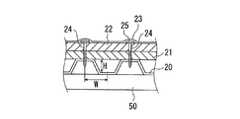
例えば、特許文献1には、梁に図5に示すような波型に折り曲げた形状の金属製折板20を載置し、その上に、下地ボード材21、断熱材22および防水層23を順次積層してなる屋根構造1が提案されている。特許文献1に記載された技術では、金属製折板20の上に下地ボード材21と断熱材22を敷き詰めて、断熱材22の上から、頭部に円盤状のディスク盤25を設けた固定金具24(ビス)を用いて金属製折板20に機械的に固定し、次に、断熱材22の上に防水シート(層)23を敷設してディスク盤表面と防水シート(層)裏面を接着して屋根構造を形成している。 For example, in
しかしながら、特許文献1に示された屋根構造では、天井などの内装面が複雑であり、しかもそのままでは取り付け用の固定金具が天井裏などの内側面に露出して、室内からの美観上問題があり、内装材を取り付けて内装面の美観を向上させる必要があり、工期が長くなり製造コストが高騰するうえ、さらには固定金具(ファスナー)に錆が発生するなどの問題があった。 However, in the roof structure shown in
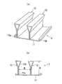
また、図6に示すような波型に折り曲げた形状の金属製折板20と、折板20の上に折り曲げられた形状の断熱材22を積層する断熱二重折板型屋根構造も実用化されている。 Further, a heat-insulated double folded plate roof structure in which a metal folded
しかし、図6に示す屋根構造では天井などの内装面が複雑であり天井の美観上問題がある。
本発明は、上記した従来技術の問題を解決して、平坦な天井面や安価に形成でき、天井内装面の美観性に優れ、しかも断熱効果や遮音効果にも優れ、さらには工事中の止水性、施工後の防水性にも優れた、屋根構造を提案することを目的とする。 The present invention solves the above-mentioned problems of the prior art, can be formed flat and inexpensively, has excellent aesthetics of the ceiling interior surface, and has excellent heat insulation and sound insulation effects. The purpose is to propose a roof structure that is water-based and waterproof after construction.
本発明の要旨はつぎのとおりである。 The gist of the present invention is as follows.
(1)梁と、該梁に載置固定される屋根用部材と、該屋根用部材の上側に積層される断熱材と、該断熱材を覆い屋根の上面を形成する防水用シートとを備える屋根構造であって、前記屋根用部材が、フラット部と、該フラット部の上方に突設されて、前記フラット部の長手方向に連続して延びる複数条のリブと、を備え、前記リブが、前記フラット部に連続する重ね合わせ部と、該重ね合わせ部の上端に形成される箱状部とを有する金属板製であり、前記断熱材が、前記箱状部に、長手方向に所定間隔を隔てて複数の止め手段で固定されてなることを特徴とする屋根構造。 (1) A beam, a roof member placed and fixed on the beam, a heat insulating material stacked on the roof member, and a waterproof sheet that covers the heat insulating material and forms an upper surface of the roof. A roof structure, wherein the roof member includes a flat portion, and a plurality of ribs protruding above the flat portion and continuously extending in a longitudinal direction of the flat portion. , Made of a metal plate having an overlapping portion continuous with the flat portion and a box-shaped portion formed at the upper end of the overlapping portion, and the heat insulating material is spaced apart from the box-shaped portion by a predetermined distance in the longitudinal direction. A roof structure characterized by being fixed by a plurality of stopping means with a gap therebetween.
(2)(1)において、前記屋根用部材の端部同士の突合せ部の下側近傍が、前記屋根用部材と前記梁との間にシーリング材を配設してなる構成を有することを特徴とする屋根構造。 (2) In (1), the lower vicinity of the abutting portion between the end portions of the roof member has a configuration in which a sealing material is disposed between the roof member and the beam. And the roof structure.
(3)(1)において、前記屋根用部材の端部同士の突合せ部の下側近傍が、前記屋根用部材と前記梁との間に屋根用部材側からシーリング材と高さ調整材とをこの順に配設してなる構成を有することを特徴とする屋根構造。 (3) In (1), the lower vicinity of the butted portion between the end portions of the roof member includes a sealing material and a height adjusting material from the roof member side between the roof member and the beam. A roof structure characterized by having a configuration arranged in this order.
(4)(1)ないし(3)のいずれかにおいて、前記複数条のリブの高さが50〜150mmの範囲内であることを特徴とする屋根構造。 (4) The roof structure according to any one of (1) to (3), wherein the height of the plurality of ribs is within a range of 50 to 150 mm.
(5)(4)において、前記複数条のリブの間隔が100〜600mmの範囲内であることを特徴とする記載の屋根構造。 (5) The roof structure according to (4), wherein an interval between the plurality of ribs is in a range of 100 to 600 mm.
(6)(1)ないし(5)のいずれかにおいて、前記止め具が、前記箱状部に10〜30mm突き出ていることを特徴とする屋根構造。 (6) The roof structure according to any one of (1) to (5), wherein the stopper protrudes 10 to 30 mm from the box-shaped portion.
本発明によれば、天井の美観および断熱効果に優れ、しかも遮音性、例えば雨音の滅音効果にも優れた軽量の陸屋根を安価に構成することができ、産業上格段の効果を奏する。また、本発明によれば、省エネルギーに寄与するという効果、があり、さらには工事中の止水性向上、施工後の防水性向上といった効果もある。 ADVANTAGE OF THE INVENTION According to this invention, the lightweight flat roof excellent in the aesthetics of a ceiling and the heat insulation effect, and also excellent in sound-insulating property, for example, the sound-deadening effect of rain sound, can be comprised cheaply, and there exists a remarkable effect on industry. Moreover, according to this invention, there exists an effect of contributing to energy saving, Furthermore, there also exists an effect of the waterproofing improvement during construction, and the waterproof improvement after construction.
本発明の屋根構造の一例を図1に断面図で示す。 An example of the roof structure of the present invention is shown in a sectional view in FIG.
本発明の屋根構造は、梁50と、該梁50に載置固定される屋根用部材1と、該屋根用部材1の上側に積層される断熱材2と、該断熱材2を覆い屋根の上面を形成する防水用シート3とを備える屋根構造10である。 The roof structure of the present invention includes a
本発明で使用する屋根用部材1は、金属板で構成される。金属板としては、とくに限定されるものではないが、めっき鋼板、ステンレス鋼板、あるいはフッ素樹脂塗装鋼板などの表面処理鋼板、またはアルミニウム板等の非鉄金属板がいずれも好適に使用できる。また、めっき鋼板としては、耐食性の観点から亜鉛めっき鋼板とすることが好ましい。 The
本発明の屋根構造で使用する屋根用部材1の一例を、図2に示す。図2(a)は斜視図、図2(b)は幅方向断面図である。 An example of the
本発明で使用する屋根用部材1は、フラット部11と複数条のリブ12,12とを備える。リブ12は、フラット部11の上方に突設され、フラット部11の長手方向に連続して延びる条として配設される。リブ12は、二枚の金属板を重ね合わせてなる重ね合わせ部12aと、重ね合わせ部12aの上端に箱状部12bを有する。重ね合わせ部12aはフラット部11に連続して形成される。なお、図2の箱状部12bは、横断面形状が三角形を呈しているが、本発明ではこれに限定されるものではない。三角形以外の四角形、五角形等の、上面が平坦な多角形状としてもよい。なお、重ね合わせ部12aは、長さ方向に所定の間隔をおいて、スポット溶接あるいは打抜き等により点接合してもよい。これにより、荷重が負荷されたときに重ね合わせ部が開くという問題は少なくなる。 The
また、リブ12aは、50〜150mmの範囲内の高さHを有することが好ましい。高さHが50 mm未満では、箱状部の加工が困難となる。一方、150mmを超えて高くなると、外圧荷重により変形しやくすくなるとともに、特性向上効果が飽和して使用する材料量に見合う部材特性の向上が得られなくなり、経済的に不利となる。 The
また、リブ12aは、幅方向に複数条配設されるが、その間隔W(重ね合わせ部間の距離)は、100〜600mmの範囲内とすることが好ましい。間隔が100mm未満では、部材構成に必要な材料量が増加しすぎて部材コストの高騰を招く。一方、600mmを超えて大きくなると、外圧荷重に対し変形しやすくなり、部材強度の低下を招く。 なお、図2に示す例は、リブが2条の場合の例であるが、本発明ではこれに限定されなるものではないことはいうまでもない。なお、リブ間隔が大きくなり、部材強度が低下する恐れのある場合には、補強用として、図3に示すようなリブ間に1つ以上のサブリブ14を設けてもよい。サブリブ14の高さ、個数、間隔は、部材強度の向上程度に応じ適宜選択でき、とくに限定されるものではない。 A plurality of
また、本発明で使用する屋根用部材1では、フラット部11は、必ずしもその面が平面である必要はなく、曲面としてもよく、また表面に凹凸模様を付与してもよい。また、本発明の屋根用部材では、強度補強の観点から、フラット部11および/またはリブ12にエンボス加工を施すこともできる。 Further, in the
また、本発明で使用する屋根用部材1の端部には、幅方向に所望の個数の屋根部材が接続可能なように、それぞれ雄型接続端13aおよび雌型接続端13bを有することが好ましい。図2に示す、接続端13a,13bは、鋼板を長さ方向にわたる折り曲げ加工により形成されたものであるが、本発明ではこれに限定されるものではない。 Moreover, it is preferable that the end of the
また、上記した構成の屋根用部材の製造方法は、とくに限定されるものではないが、金属板にロール成形加工を施し、幅方向にフラット部と所定間隔に設定した複数条のリブと、あるいはさらに両幅端における接続端とを形成し、さらに、剪断加工により所定長さの部材とする方法が好ましい。 In addition, the method for manufacturing the roof member having the above-described configuration is not particularly limited, and a roll forming process is performed on the metal plate, and a plurality of ribs set at a predetermined interval with a flat portion in the width direction, or Further, it is preferable to form a connection end at both width ends and further form a member having a predetermined length by shearing.
本発明で使用する屋根構造10は、上記した構造の屋根部材1を1個または必要に応じて幅方向に複数個接続し、あるいはさらに屋根部材を長さ方向に突き合せて、所望の大きさ(幅×長さ)の屋根部材とする。ついで、屋根用部材1,1の上側に所望厚さの断熱材2を積層し、さらに断熱材2を覆うように防水シート3を重ね、屋根面を形成する。なお、断熱材の下側に所定厚さの断熱材や下地ボード材を積層しても何ら問題はない。 The
断熱材2は、長手方向に所定間隔を隔てて止め手段4である複数の止め具4bで、箱状部12b(屋根部材1)に固定される。断熱材2は、ディスクまたは固定金具4aを介して止め具4bで固定されることが好ましい。止め具4bは、10〜30mmだけ箱状部12bに突き出るような長さとすることが好ましい。止め具の突き出し長さが10mm未満では、ヒートブリッジにより結露を発生させる危険性が高くなるとともに固定後の安定性に不安がある。一方、30mmを超えて長くなると、止め具のコストが高くなり経済的に不利となるとともに、止め具先端が箱状部12bに接触し先端が破損し、作業性が低下するという問題が生じる危険性が高くなる。 The
また、断熱材2は箱状部12bに固定するほかに、フラット部11上に所定の厚さ積層してもよい。 In addition to fixing the
なお、断熱材や下地ボード材としては、硬質ウレタンボード、発砲スチレンボード、ガラス繊維ボード、ロックウールボード、木片セメント板、木毛セメント板、フェノール樹脂系ボード等が例示できる。また、屋根面を形成する防水シート3は、塩化ビニル系シート、アスファルト系シート、ゴム系シート、エチレンプロパレン系シート、金属板等の材料とすることが好ましい。なお、防水シート3の重ね合わせ部や、防水シート3と下層の材料(例えば、デスク4a)との接合は、熱、溶剤、はぜ締め、接着剤等により行うことが好ましい。 Examples of the heat insulating material and the base board material include hard urethane board, foamed styrene board, glass fiber board, rock wool board, wood piece cement board, wood wool cement board, phenol resin board and the like. The
より広い屋根空間を構成するために、屋根部材1同士を、長さ方向端部で突き合せる場合に、本発明の屋根構造では、図4(a)に示すように、屋根用部材1の端部同士の突合せ部101の下側近傍が、屋根用部材1の下側と梁50との間にシーリング材5を配設した構成を有することが好ましい。これにより、水密性・気密性が向上し突合せ部からの水漏れを防止することができ、施工後の防水はもちろん工事中の止水を効果的に行うことができる。シーリング材としては、水密性・気密性を有する不定形の材料、あるいは水密性・気密性を有するテープ状材料とすることが好ましい。シーリング材の材質としてはブチルゴム系、アスファルト瀝青材系、あるいはウレタン系、変性シリコン系とすることが好ましい。なお、シーリング材の厚さは、0.5〜1.5 mm程度とすることが好ましい。 In order to construct a wider roof space, when the
また、図4(b)に示すように、屋根用部材の端部同士の突合せ部101の下側近傍が、屋根用部材の下側から梁50との間にシーリング材5と高さ調整材6とをこの順に配設した構成を有することが好ましい。梁50がハイテンボルト等による継手部を有する場合には梁上面の高さが一定とならないため、梁50と屋根用部材1との間に、C型チャンネル等の高さ調整材6を介してシーリング材5を配置することが好ましい。 Further, as shown in FIG. 4B, the sealing
上記した構成の屋根構造とすることにより、断熱材2の下層に、対流が生じにくい所定量の空気層を確保でき、断熱効果が顕著に向上し、省エネルギーに貢献できる。また、止め手段4が箱状部内に隠れるとともに、フラット部により天井面を平坦に形成できるという効果がある。なお、断熱材を箱状部以外にフラット部11上に積層することにより、断熱性、遮音性がさらに向上する。 By setting it as the roof structure of the above-mentioned structure, the predetermined amount of air layer which cannot produce a convection easily can be ensured in the lower layer of the
(実施例1)
JIS G 3302に規定される溶融亜鉛めっき鋼板SGC 490(板厚:0.8mm)を用いて図1に示す形状の屋根用部材(本発明例)を作製した。屋根用部材1は、めっき鋼板に、ロール成形加工により、幅方向にフラット部11と、所定間隔Wを隔てて2条の高さHのリブ12と、さらに両幅端に雄、雌型の接続端13を形成し、さらに、剪断加工により最大長さ(12m)に切断して使用した。この屋根用部材1を幅端の接続端13a、13bにより幅方向に接続した。これらを、梁50に載置して屋根構造10を構成した。なお、屋根用部材1の上に、ボード状の断熱材1(厚み:30mm)を積層し、ディスク4aを介して止め具(ビス)4bでリブ12の箱状部12bに固定した。ついで、断熱材2を塩化ビニル系防水材(シート:厚さ1.5mm)3で覆い、屋根を形成した。なお、ディスク4aの表面と防水シート3の裏面とを接着材で固定した。なお、リブの幅方向の間隔Wを200mm、高さHを100mm、止め具突き出量Iを20mmとした。(Example 1)
Using a hot dip galvanized steel sheet SGC 490 (plate thickness: 0.8 mm) defined in JIS G 3302, a roof member having the shape shown in FIG. 1 (example of the present invention) was produced. The
なお、従来例1として、屋根用部材に、図5に示すような、波型形状の金属製折板を用いた以外は、断熱材の種類、厚さ、止め具の大きさ等は本発明例と同様した。なお、金属製折板は、頂部と底部の間隔Wを100mm、頂部の高さHを75 mmとする形状のめっき鋼板(板厚:1.2 mm)製とした。 In addition, as a prior art example 1, except for using the corrugated metal folding plate as shown in FIG. Same as example. The metal folded plate was made of a plated steel plate (plate thickness: 1.2 mm) having a top-to-bottom distance W of 100 mm and a top height H of 75 mm.
また、従来例2として、図6に示すような断熱二重折板型屋根構造を構成した。屋根用部材として使用した金属製折板は従来例1と同様とし、断熱材の種類はグラスウール10kg/m3とした。なお断熱材の厚さは計算値50mm〜75mmとした。Further, as Conventional Example 2, a heat insulating double folded plate roof structure as shown in FIG. The metal folded plate used as the roof member was the same as that in Conventional Example 1, and the type of the heat insulating material was 10 kg / m3 of glass wool. The thickness of the heat insulating material was calculated to be 50 mm to 75 mm.
上記した構造の屋根構造について、断熱性、雨音減音効果、耐結露性を評価した。断熱性は、熱量流量を計算により求め、従来例2を基準(○)にしてそれより優れている場合を◎、それより劣る場合を△とした。また、雨音減音効果は、人工的に降雨を実行し、その際の室内での平均音圧を測定し、従来例2を基準(○)にして、それより優れる場合を◎、それより劣る場合を△とした。また、耐結露性は、外気温を−3℃、室内温度を15℃、室内湿度を50%の条件で、従来例2を基準(○)としてそれより優れる場合を◎、それより劣る場合を△として評価した。 The roof structure having the above-described structure was evaluated for heat insulation, rain sound reduction effect, and condensation resistance. For the heat insulation, the heat flow rate was obtained by calculation, and the case where it was superior to that of the conventional example 2 as a reference (◯) was indicated by ◎, and the case where it was inferior was indicated by △. In addition, the sound reduction effect of rain sound is artificially executed by rainfall, and the average sound pressure in the room at that time is measured. The case where it was inferior was rated as Δ. Condensation resistance is ◎ when the outside temperature is −3 ° C., the room temperature is 15 ° C., and the room humidity is 50%. Evaluated as △.
得られた結果を表1に示す。 The obtained results are shown in Table 1.

表1から、本発明例は従来例に比べて高い断熱性、優れた雨音減音効果、優れた耐結露性を有する屋根構造となっている。 From Table 1, the example of the present invention has a roof structure having higher heat insulation, excellent rain sound reduction effect, and better dew condensation resistance than the conventional example.
(実施例2)
実施例1で示した本発明例である屋根構造について、図4に示すように屋根用部材1の端部同士の突合せ部101の下側を梁との間にシーリング材5を配設し室内への漏水状況を目視で観察した。シーリング材としては、ブチルゴム系材(厚み:1mm)を用いた。その結果、突合せ部の下側にシーリング材を配設することにより、漏水を完全に防止できた。さらに、突合せ部にシーリング材を配設することにより、室内への汚れた空気の流入も防止できるという効果がある。(Example 2)
In the roof structure according to the present invention shown in the first embodiment, as shown in FIG. 4, the sealing
1 屋根用部材
5 シーリング材
6 高さ調整材
10 屋根構造
11 フラット部
12 リブ
12a 重ね合わせ部
12b 箱状部
13a 接続端(雄)
13b 接続端(雌)
14 サブリブ
20 金属製折板
21 耐火材
22 断熱材
23 防水シート(層)
24 固定金具(ビス)
25 ディスク盤
50 梁
101 突合せ部1
10 Roof structure
11 Flat part
12 ribs
12a Overlapping part
12b Box
13a Connection end (male)
13b Connection end (female)
14 Sub-rib
20 Metal folded board
21 Refractory material
22 Insulation
23 Tarpaulin (layer)
24 Fixing bracket (screw)
25 disc
50 beams
101 butt
Claims (6)
Translated fromJapanesePriority Applications (1)
| Application Number | Priority Date | Filing Date | Title |
|---|---|---|---|
| JP2003413063AJP2005171623A (en) | 2003-12-11 | 2003-12-11 | Roof structure |
Applications Claiming Priority (1)
| Application Number | Priority Date | Filing Date | Title |
|---|---|---|---|
| JP2003413063AJP2005171623A (en) | 2003-12-11 | 2003-12-11 | Roof structure |
Publications (1)
| Publication Number | Publication Date |
|---|---|
| JP2005171623Atrue JP2005171623A (en) | 2005-06-30 |
Family
ID=34733306
Family Applications (1)
| Application Number | Title | Priority Date | Filing Date |
|---|---|---|---|
| JP2003413063APendingJP2005171623A (en) | 2003-12-11 | 2003-12-11 | Roof structure |
Country Status (1)
| Country | Link |
|---|---|
| JP (1) | JP2005171623A (en) |
Cited By (16)
| Publication number | Priority date | Publication date | Assignee | Title |
|---|---|---|---|---|
| JP2007211563A (en)* | 2006-02-13 | 2007-08-23 | Jfe Galvanizing & Coating Co Ltd | Roof member and roof structure |
| JP2007277936A (en)* | 2006-04-07 | 2007-10-25 | Tajima Roofing Co Ltd | Waterproof heat-insulation structure and heat-insulation substrate for use therein |
| WO2011011596A1 (en) | 2009-07-23 | 2011-01-27 | Haddock Robert M M | Roof framing structure using triangular structural framing |
| US10443896B2 (en) | 2016-07-29 | 2019-10-15 | Rmh Tech Llc | Trapezoidal rib mounting bracket with flexible legs |
| US10502457B2 (en) | 2010-03-03 | 2019-12-10 | Robert M. M. Haddock | Photovoltaic module mounting assembly |
| US10634175B2 (en) | 2011-12-29 | 2020-04-28 | Rmh Tech Llc | Mounting device for nail strip panels |
| US10640980B2 (en) | 2016-10-31 | 2020-05-05 | Rmh Tech Llc | Metal panel electrical bonding clip |
| US10731355B2 (en) | 2011-02-25 | 2020-08-04 | Rmh Tech Llc | Mounting device for building surfaces having elongated mounting slot |
| US10903785B2 (en) | 2018-03-21 | 2021-01-26 | Rmh Tech Llc | PV module mounting assembly with clamp/standoff arrangement |
| US10948002B2 (en) | 2018-12-14 | 2021-03-16 | Rmh Tech Llc | Mounting device for nail strip panels |
| US11041310B1 (en) | 2020-03-17 | 2021-06-22 | Rmh Tech Llc | Mounting device for controlling uplift of a metal roof |
| US11352793B2 (en) | 2020-03-16 | 2022-06-07 | Rmh Tech Llc | Mounting device for a metal roof |
| US11774143B2 (en) | 2017-10-09 | 2023-10-03 | Rmh Tech Llc | Rail assembly with invertible side-mount adapter for direct and indirect mounting applications |
| JP7612310B2 (en) | 2021-12-29 | 2025-01-14 | 鹿島建設株式会社 | Heat-insulating and sound-proof roof structure |
| US12203496B2 (en) | 2020-07-09 | 2025-01-21 | Rmh Tech Llc | Mounting system, device, and method |
| USD1075493S1 (en) | 2022-07-06 | 2025-05-20 | Rmh Tech Llc | Clamp for a photovoltaic module mounting assembly |
- 2003
- 2003-12-11JPJP2003413063Apatent/JP2005171623A/enactivePending
Cited By (39)
| Publication number | Priority date | Publication date | Assignee | Title |
|---|---|---|---|---|
| JP2007211563A (en)* | 2006-02-13 | 2007-08-23 | Jfe Galvanizing & Coating Co Ltd | Roof member and roof structure |
| JP2007277936A (en)* | 2006-04-07 | 2007-10-25 | Tajima Roofing Co Ltd | Waterproof heat-insulation structure and heat-insulation substrate for use therein |
| WO2011011596A1 (en) | 2009-07-23 | 2011-01-27 | Haddock Robert M M | Roof framing structure using triangular structural framing |
| US8312678B1 (en)* | 2009-07-23 | 2012-11-20 | Haddock Robert M M | Roof framing structure using triangular structural framing |
| US8656649B2 (en) | 2009-07-23 | 2014-02-25 | Robert M. M. Haddock | Roof framing structure using triangular structural framing |
| US20140360119A1 (en)* | 2009-07-23 | 2014-12-11 | Robert M.M. Haddock | Roof framing structure using triangular structural framing |
| EP2456929A4 (en)* | 2009-07-23 | 2015-12-02 | Robert M M Haddock | Roof framing structure using triangular structural framing |
| US9222263B2 (en)* | 2009-07-23 | 2015-12-29 | Robert M. M. Haddock | Roof framing structure using triangular structural framing |
| US10502457B2 (en) | 2010-03-03 | 2019-12-10 | Robert M. M. Haddock | Photovoltaic module mounting assembly |
| US10731355B2 (en) | 2011-02-25 | 2020-08-04 | Rmh Tech Llc | Mounting device for building surfaces having elongated mounting slot |
| US11885139B2 (en) | 2011-02-25 | 2024-01-30 | Rmh Tech Llc | Mounting device for building surfaces having elongated mounting slot |
| US11035126B2 (en) | 2011-02-25 | 2021-06-15 | Rmh Tech Llc | Mounting device for building surfaces having elongated mounting slot |
| US10634175B2 (en) | 2011-12-29 | 2020-04-28 | Rmh Tech Llc | Mounting device for nail strip panels |
| US11333179B2 (en) | 2011-12-29 | 2022-05-17 | Rmh Tech Llc | Mounting device for nail strip panels |
| US12018861B2 (en) | 2011-12-29 | 2024-06-25 | Rmh Tech Llc | Mounting device for nail strip panels |
| US12044443B2 (en) | 2016-07-29 | 2024-07-23 | Rmh Tech Llc | Trapezoidal rib mounting bracket with flexible legs |
| US10859292B2 (en) | 2016-07-29 | 2020-12-08 | Rmh Tech Llc | Trapezoidal rib mounting bracket with flexible legs |
| US11573033B2 (en) | 2016-07-29 | 2023-02-07 | Rmh Tech Llc | Trapezoidal rib mounting bracket with flexible legs |
| US10443896B2 (en) | 2016-07-29 | 2019-10-15 | Rmh Tech Llc | Trapezoidal rib mounting bracket with flexible legs |
| US11085188B2 (en) | 2016-10-31 | 2021-08-10 | Rmh Tech Llc | Metal panel electrical bonding clip |
| US10640980B2 (en) | 2016-10-31 | 2020-05-05 | Rmh Tech Llc | Metal panel electrical bonding clip |
| US11808043B2 (en) | 2016-10-31 | 2023-11-07 | Rmh Tech Llc | Metal panel electrical bonding clip |
| US11774143B2 (en) | 2017-10-09 | 2023-10-03 | Rmh Tech Llc | Rail assembly with invertible side-mount adapter for direct and indirect mounting applications |
| US11616468B2 (en) | 2018-03-21 | 2023-03-28 | Rmh Tech Llc | PV module mounting assembly with clamp/standoff arrangement |
| US12231081B2 (en) | 2018-03-21 | 2025-02-18 | Rmh Tech Llc | PV module mounting assembly with clamp/standoff arrangement |
| US10903785B2 (en) | 2018-03-21 | 2021-01-26 | Rmh Tech Llc | PV module mounting assembly with clamp/standoff arrangement |
| US10948002B2 (en) | 2018-12-14 | 2021-03-16 | Rmh Tech Llc | Mounting device for nail strip panels |
| US11668332B2 (en) | 2018-12-14 | 2023-06-06 | Rmh Tech Llc | Mounting device for nail strip panels |
| US12320375B2 (en) | 2018-12-14 | 2025-06-03 | Rmh Tech Llc | Mounting device for nail strip panels |
| US11965337B2 (en) | 2020-03-16 | 2024-04-23 | Rmh Tech Llc | Mounting device for a metal roof |
| US11512474B2 (en) | 2020-03-16 | 2022-11-29 | Rmh Tech Llc | Mounting device for a metal roof |
| US11352793B2 (en) | 2020-03-16 | 2022-06-07 | Rmh Tech Llc | Mounting device for a metal roof |
| US12305397B2 (en) | 2020-03-16 | 2025-05-20 | Rmh Tech Llc | Mounting device for a metal roof |
| US11739529B2 (en) | 2020-03-16 | 2023-08-29 | Rmh Tech Llc | Mounting device for a metal roof |
| US11041310B1 (en) | 2020-03-17 | 2021-06-22 | Rmh Tech Llc | Mounting device for controlling uplift of a metal roof |
| US11788291B2 (en) | 2020-03-17 | 2023-10-17 | Rmh Tech Llc | Mounting device for controlling uplift of a metal roof |
| US12203496B2 (en) | 2020-07-09 | 2025-01-21 | Rmh Tech Llc | Mounting system, device, and method |
| JP7612310B2 (en) | 2021-12-29 | 2025-01-14 | 鹿島建設株式会社 | Heat-insulating and sound-proof roof structure |
| USD1075493S1 (en) | 2022-07-06 | 2025-05-20 | Rmh Tech Llc | Clamp for a photovoltaic module mounting assembly |
Similar Documents
| Publication | Publication Date | Title |
|---|---|---|
| JP2005171623A (en) | Roof structure | |
| US7021023B2 (en) | Standing seam roof and method of manufacturing same | |
| US9181692B1 (en) | Covering system for a building substrate | |
| US4432181A (en) | Wall construction for architectural structure | |
| US7107732B2 (en) | Purlin clip for an insulated ceiling of a metal building | |
| JP6147054B2 (en) | Parapet waterproof structure | |
| JP7193410B2 (en) | Interlocking roofing material and joining structure of interlocking roofing material | |
| CN201273022Y (en) | Heat-preserving energy-saving movable house | |
| JP2007211563A (en) | Roof member and roof structure | |
| WO2022055380A1 (en) | Modular roofing panel and method of installing roof covering | |
| JP5189401B2 (en) | Thermal insulation roof panel | |
| JP5516927B2 (en) | Exterior material | |
| JP2007309074A (en) | Eaves edge member and remodeling structure therewith | |
| WO2020189385A1 (en) | Roof structure | |
| JP4030485B2 (en) | Roof and wall components | |
| JP4104504B2 (en) | Double-sided metal insulation panel | |
| JP2018199990A (en) | Engaging structure of thin plate roof member and eaves arabesque member and its assembly construction method | |
| JP2015190174A (en) | Construction panels and panel bodies | |
| JP2907324B2 (en) | Exterior structure of building | |
| JP3177930U (en) | Corrugated plate fixing member | |
| JP6208969B2 (en) | Roof panel connection structure | |
| KR200463541Y1 (en) | Roof base structure | |
| EP1530663A1 (en) | Hidden fastening insulating panel for building roofs and roof thereby obtained | |
| KR20150030919A (en) | Prefab construction-absorbing insulation support Panel | |
| JP2007315100A (en) | Accessory for outer covering panel |
Legal Events
| Date | Code | Title | Description |
|---|---|---|---|
| A621 | Written request for application examination | Effective date:20061016 Free format text:JAPANESE INTERMEDIATE CODE: A621 | |
| A977 | Report on retrieval | Effective date:20081121 Free format text:JAPANESE INTERMEDIATE CODE: A971007 | |
| A131 | Notification of reasons for refusal | Effective date:20090908 Free format text:JAPANESE INTERMEDIATE CODE: A131 | |
| A02 | Decision of refusal | Effective date:20100112 Free format text:JAPANESE INTERMEDIATE CODE: A02 |