JP2005168820A - Endoscope holder - Google Patents
Endoscope holderDownload PDFInfo
- Publication number
- JP2005168820A JP2005168820AJP2003413408AJP2003413408AJP2005168820AJP 2005168820 AJP2005168820 AJP 2005168820AJP 2003413408 AJP2003413408 AJP 2003413408AJP 2003413408 AJP2003413408 AJP 2003413408AJP 2005168820 AJP2005168820 AJP 2005168820A
- Authority
- JP
- Japan
- Prior art keywords
- endoscope
- holding
- freedom
- switch
- unit
- Prior art date
- Legal status (The legal status is an assumption and is not a legal conclusion. Google has not performed a legal analysis and makes no representation as to the accuracy of the status listed.)
- Granted
Links
Images


Landscapes
- Endoscopes (AREA)
Abstract
Description
Translated fromJapanese本発明は、内視鏡を保持する内視鏡保持装置に関する。 The present invention relates to an endoscope holding apparatus that holds an endoscope.
近年、たとえば脳神経外科において手術用顕微鏡を用いての、いわゆるマイクロサージャリーが頻繁に行われている。特に、手術用顕微鏡の観察範囲は頭蓋の開創部を通して観察できる範囲に限られており、手術用顕微鏡では見えない部分(死角)がある。このような手術用顕微鏡では見えない死角部分を観察するために内視鏡が用いられる。
そして、内視鏡観察像を見ながら頭蓋内の治療部位に処置具を挿入してマイクロサージャリーが行われるが、頭蓋内は神経、血管等の重要組織が複雑かつ微細に絡み合って構成されているので、組織を傷付けないように内視鏡を微細かつスムーズに移動させ、正確な位置に保持する保持装置を必要としている。In recent years, for example, so-called microsurgery using a surgical microscope is frequently performed in neurosurgery. In particular, the observation range of the surgical microscope is limited to the range that can be observed through the retracted portion of the skull, and there is a portion (dead angle) that cannot be seen with the surgical microscope. An endoscope is used to observe a blind spot portion that cannot be seen with such a surgical microscope.
Microsurgery is performed by inserting a treatment tool into the treatment site in the skull while observing the endoscopic observation image. The inside of the skull is composed of complex and finely entangled important tissues such as nerves and blood vessels. Therefore, a holding device that moves the endoscope finely and smoothly so as not to damage the tissue and holds it in an accurate position is required.
[特許文献1]には、内視鏡の使用中に内視鏡を保持して術者の疲労を低減する一方で、内視鏡を使用する術者の手元近傍に、内視鏡周辺装置を操作するスイッチ部を設けて、周辺装置の操作を容易にする内視鏡保持装置が記載されている。
[特許文献2]には、挿入部の長さが異なる様々な内視鏡を、使用する目的に合わせて任意の挿入部長に調整して使用可能とし、内視鏡を操作し易いようにした内視鏡保持装置が記載されている。[Patent Document 1] describes an endoscope peripheral device in the vicinity of a hand of an operator who uses an endoscope while holding the endoscope while using the endoscope to reduce fatigue of the operator. There is described an endoscope holding device that is provided with a switch unit for operating the device to facilitate the operation of peripheral devices.
In [Patent Document 2], various endoscopes with different insertion lengths can be adjusted to any insertion length according to the purpose of use, and the endoscope can be operated easily. An endoscope holding device is described.
[特許文献3]には、術者が持ち易いようにして操作の容易化を図り、内視鏡保持具に内視鏡を固定して処置等の作業を行う場合に、顕微鏡による観察や処置等の作業の邪魔にならずにすみ、内視鏡を術部に挿入した際には、内視鏡と術部の温度差によって生じる内視鏡の観察光学系の曇りを防止する内視鏡と内視鏡保持装置が記載されている。
上述した[特許文献1〜3]の内視鏡保持装置においては、いずれも術者が内視鏡を保持し易い構造をなし、長時間の手術下であっても術者の疲労軽減化を図っていて、その点については満足する結果が得られている。
In the endoscope holding devices described in [
ところで、特に脳神経外科手術で行われる内視鏡手技については、挿入部の精密な挿入操作が要求されている。既存の内視鏡装置によっては、一人の術者が片手で挿入部を持ち、もう一方の片手で操作部を持ったまま挿入量、方向および先端湾曲部の操作に加えて内視鏡全体の軸周りの回転操作を行う必要がある。
挿入部と操作部との間は、消化器内視鏡のような十分な間隔が取れていないため、挿入部を捩って操作部の捩りを与えない使い方をすると、回転方向に戻ろうとする力を支えながらの挿入部の操作となり、精密な挿入操作の妨げとなる。あるいは、挿入部と操作部との間に十分な間隔を得るために、これらの間に必要以上のたるみを持たせた長尺部分を形成すると、術者はそのたるみ部分をぶら下げた状態で挿入操作を行うこととなり、やはり精密な挿入操作の妨げとなる。By the way, particularly for an endoscopic technique performed in a neurosurgery operation, a precise insertion operation of an insertion portion is required. Depending on the existing endoscope apparatus, one operator has the insertion part with one hand and the operation part with the other hand, in addition to the operation of the insertion amount, direction and tip bending part, It is necessary to perform rotation around the axis.
Since there is not enough space between the insertion part and the operation part as in the case of a digestive endoscopy, if the insertion part is twisted and the operation part is not twisted, it tends to return to the rotation direction. Operation of the insertion portion while supporting the force is hindered and precise insertion operation is hindered. Alternatively, in order to obtain a sufficient space between the insertion part and the operation part, if a long part having a slack more than necessary is formed between them, the operator inserts the slack part in a suspended state. Operation will be performed, and it will also hinder precise insertion operation.
このようにして、脳神経外科手術で行われる内視鏡手技は高度の熟練を要するので、専門科の一部術者にしか行えないのが実情である。内視鏡を使いこなせる術者の範囲を可能な限り拡大するためにも、操作の簡便化を図るとともに、正確性の向上化を得られるようにした内視鏡保持装置が求められている。 In this way, the endoscopic technique performed in neurosurgery requires a high degree of skill, so that it can be performed only by a part of specialists. In order to expand the range of surgeons who can use the endoscope as much as possible, there is a need for an endoscope holding apparatus that is easy to operate and can improve accuracy.
本発明は前記事情に着目してなされたものであり、その目的とするところは、操作性向上や術者の疲労軽減に加えて、内視鏡操作の正確性の向上化を得る内視鏡保持装置を提供しようとするものである。 The present invention has been made paying attention to the above-mentioned circumstances, and an object of the present invention is to provide an endoscope that improves the accuracy of endoscopic operation in addition to improving operability and reducing operator fatigue. A holding device is to be provided.
本発明は上述の目的を満足するためになされたものであり、請求項1として、先端が術部に挿入される挿入部と、この挿入部の基端側に連設される柔軟性を有する中間部と、この中間部を介して挿入部と連結され挿入部先端を操作する操作部とを備えた内視鏡を保持する内視鏡保持装置において、内視鏡における挿入部を術部に対して位置決め保持する第1の保持手段と、内視鏡における操作部を術部周辺の空間である術空間から外れた位置に位置決め保持する第2の保持手段を具備する。 The present invention has been made to satisfy the above-mentioned object, and as claimed in
請求項2として、請求項1記載の内視鏡保持装置において第1の保持手段は、挿入部を軸方向に沿ってスライド自在とする自由度および挿入部を軸回りに回転自在とする自由度との2自由度に対して固定保持しもしくは固定保持を解除する第1の制御手段と、挿入部を空間の所望の位置に保持する保持装置の固定もしくは固定を解除する第2の制御手段とを具備する。
請求項3として、請求項1記載の内視鏡保持装置において前記第2の保持手段は、操作部を軸回りに回転自在とする自由度の1自由度のみについて固定保持しもしくは固定保持を解除する第3の制御手段と、操作部を空間の所望の位置に保持する保持装置の固定もしくは固定を解除する第4の制御手段とを具備する。According to a second aspect of the present invention, in the endoscope holding device according to the first aspect, the first holding means has a degree of freedom to allow the insertion portion to slide along the axial direction and a degree of freedom to allow the insertion portion to rotate about the axis. And a second control means for releasing or fixing the holding device for holding the insertion portion at a desired position in the space; It comprises.
According to a third aspect of the present invention, in the endoscope holding device according to the first aspect, the second holding means holds or releases the fixed holding only for one degree of freedom in which the operation portion is rotatable about the axis. And a fourth control means for releasing or fixing the holding device that holds the operation unit at a desired position in the space.
このような構成を採用することにより、術部に対して挿入部を保持し、術空間から外れた位置に操作部を保持して、挿入部および操作部の操作がし易い位置および姿勢に固定でき、挿入部と操作部とを連結する中間部は挿入部から手術を邪魔しないルートを通って術空間から離間し、術空間から外れた操作部に至る。
そして、一時的に観察方向を変更するような場合には、挿入部のみの軸回り回転による操作を併用しつつ、挿入部の軸回り回転に応じた操作部の軸回り回転を与える操作を併用することによって、精密な挿入操作が可能となる。By adopting such a configuration, the insertion unit is held with respect to the surgical site, the operation unit is held at a position outside the surgical space, and the insertion unit and the operation unit are easily operated and fixed in a position and posture. The intermediate portion that connects the insertion portion and the operation portion is separated from the operation space through a route that does not disturb the operation from the insertion portion, and reaches the operation portion that is out of the operation space.
And when changing the observation direction temporarily, combined with the operation to rotate around the axis of the operation part according to the rotation around the axis of the insertion part while using the operation by rotation around the axis of only the insertion part By doing so, a precise insertion operation becomes possible.
本発明によれば、内視鏡の位置決めの作業性向上を得られるとともに、内視鏡に対する位置決めの正確性が向上するなどの効果を奏する。 According to the present invention, it is possible to improve the positioning workability of the endoscope and to improve the positioning accuracy with respect to the endoscope.
以下、図面を参照して本発明の内視鏡保持装置における第1の実施の形態について説明する。
図1は、内視鏡Sおよび、この内視鏡Sを保持する内視鏡保持装置Nの全体構成を示す説明図である。
手術台G上に被検体(患者)が仰臥しており、頭部に内視鏡Sを構成する挿入部5の先端一部が被検体の術部に挿入されている状態を概略的に示している。前記内視鏡Sは、後述するように前記挿入部5と軟性の中間部2を介して繋げられる操作部1とから構成される。Hereinafter, a first embodiment of an endoscope holding apparatus of the present invention will be described with reference to the drawings.
FIG. 1 is an explanatory diagram showing an overall configuration of an endoscope S and an endoscope holding apparatus N that holds the endoscope S.
The subject (patient) lies on the operating table G and schematically shows a state in which a part of the distal end of the
前記内視鏡保持装置Nは、後述するように内視鏡Sの前記挿入部5を術部に対して位置決め保持する先端側保持機構(第1の保持手段)12と、内視鏡Sの前記操作部1を術空間から外れた位置に位置決め保持する操作部用保持機構(第2の保持手段)20とから構成される。
前記先端側保持機構12は、内視鏡Sの挿入部5を軸方向に沿ってスライド自在とする自由度および、挿入部5を軸回りに回転自在とする自由度との2自由度に対して固定保持し、もしくは固定保持を解除する第1のスイッチ(第1の制御手段)15と、挿入部5を前記2自由度を除く自由度について固定保持し、もしくは固定保持を解除する第2のスイッチ(第2の制御手段)16とを備えている。The endoscope holding device N includes a distal-side holding mechanism (first holding means) 12 for positioning and holding the
The distal-end-
前記操作部用保持機構20は、内視鏡Sの前記操作部1を軸回りに回転自在とする自由度の1自由度のみについて固定保持し、もしくは固定保持を解除する第3のスイッチ(第3の制御手段)23と、操作部1を前記1自由度を除く自由度について固定保持し、もしくは固定保持を解除する第4のスイッチ(第4の制御手段)24とを備えている。
つぎに、内視鏡Sと内視鏡保持装置Nのそれぞれについて詳細に説明する。
図2は、内視鏡Sの一部斜視図である。この内視鏡Sは、手元側に備えられる前記操作部1と、この操作部1の先端側に連結される軟性の前記中間部2と、この中間部2の先端側に設けられる硬性部3および、この硬性部3のさらに先端側に設けられる湾曲部4を備えていて、前記硬性部3と湾曲部とで挿入部5が構成される。The operation
Next, each of the endoscope S and the endoscope holding device N will be described in detail.
FIG. 2 is a partial perspective view of the endoscope S. FIG. The endoscope S includes the
図2は、内視鏡Sにおいて挿入部5を構成する硬性部3に、内視鏡保持装置Nの一部を構成する係止部6を取付けた状態を示す斜視図である。
前記係止部6の具体的な構造は図示していないが、先に本出願人が出願した特開2001−149302号公報の図3に示すハンドル用把持部4のように、本体内に硬性部3が軸方向に沿って挿通する挿通管路が形成され、この挿通管路に挿通する硬性部3の外周面に当接可能な固定手段を備えていて、硬性部3を任意の位置で固定できる。
前記係止部6は固定・解除ボタン7を備えていて、このボタンを指で押すことにより固定手段の硬性部3に対する固定を解除してフリー状態となし、ボタンから指を離すことにより固定手段が作用して硬性部3を強制的に固定できるようになっている。FIG. 2 is a perspective view showing a state in which the locking portion 6 constituting a part of the endoscope holding device N is attached to the
Although the specific structure of the locking portion 6 is not shown in the drawing, it is hard in the main body like the
The locking portion 6 is provided with a fixing / releasing button 7, and when the button is pressed with a finger, the fixing means is released from being fixed to the
したがって、係止部6は硬性部3に対して単独に、かつ任意に位置調整が可能であり、係止部6は固定時に前記先端側保持機構12により挿入量が制限されるため誤挿入防止の機能を持つとともに、係止部6の固定時は硬性部3の軸回りの回転操作を行うツマミとして機能する。
図4は、前記操作部1を拡大して示す斜視図である。
前記操作部1には、前記湾曲部4を湾曲操作するための操作レバー10と、鉗子等の処置具を挿入するための口金部9が設けられる。この口金部9から挿入される鉗子は、操作部1から中間部2と硬性部3を介して湾曲部4の先端、すなわち挿入部5の先端から突没自在である。操作部1の基端部は一段直径が細くなった円柱形状に形成され、後述するようにして保持される受け部11が設けられている。Therefore, the position of the locking part 6 can be adjusted independently and arbitrarily with respect to the
FIG. 4 is an enlarged perspective view showing the
The
図5は、挿入部1を保持する先端側保持機構(第1の保持手段)12の構成を概略的に示す説明図である。
前記先端側保持機構12は、基端部にたとえば手術台Gの一部に着脱自在に取付けられる設置部Aを備えている。設置部Aとして、たとえば定位脳装置のごとく、頭蓋に直接固定する構成もあり得る。先端側保持機構12の先端部には、挿入部1の硬性部3を把持する把持部13が設けられる。
前記設置部Aと把持部13との間はアーム機構部14となっていて、このアーム機構部14は、たとえば先に本出願人が出願した特開平7−289563号公報における図1の構成のようになっている。FIG. 5 is an explanatory diagram schematically showing the configuration of the distal end side holding mechanism (first holding means) 12 that holds the
The distal end
An
具体的には、アーム機構部14は電磁ブレーキが組み込まれて受動的に動く複数の関節と、これら関節相互間に連結されるアームを備えている。電磁ブレーキを解除して複数の関節を駆動し硬性部3を把持する把持部13を3次元空間の所望の位置に所望の姿勢となるように移動したあと、電磁ブレーキを固定すると硬性部3の位置および姿勢を保持することができる。
前記把持部13は、先に本出願人が出願した特開平6−22901号公報における図9に記載されているホールド部の構成と略同一である。具体的には、硬性部3が挿通するとともに、摩擦を利用して硬性部3を確実に保持する受け枠と、この受け枠と一体に連結される電磁クラッチを備えている。電磁クラッチを駆動することにより受け枠の硬性部3に対する固定と、半固定、もしくは解除を選択して行えるようになっている。Specifically, the
The
前記把持部13の上面には、把持部13を構成する電磁クラッチを駆動制御する第1のスイッチ(第1の制御手段)15および第2のスイッチ(第2の制御手段)16が並設される。
前記第1のスイッチ15は、把持部13を制御して硬性部3である挿入部5を軸方向に沿ってスライド自在となす自由度(延出方向併進自由度)と、挿入部5を軸回りに回転自在とする自由度(延出方向軸回り回転自由度)との2自由度について固定状態と解除状態を選択できる。解除状態は半固定状態とする設計もあり得る。第2のスイッチ16は、把持部13を制御してアーム機構14について固定保持し、もしくは固定保持を解除することができる。A first switch (first control means) 15 and a second switch (second control means) 16 for driving and controlling the electromagnetic clutch constituting the gripping
The
ちなみに、「固定」とは軽い操作力では動かない状態を意味し、「半固定」とは自然に動き出すことのない固定状態であって操作力で動かせる。「解除」とは、人為的に支えていなければ自重あるいはその他の力によって動いてしまう状態を言う。
なお、ここでは把持部13上面に第1のスイッチ15と第2のスイッチ16を並設したが、これに限定されるものではなく、たとえば第1のスイッチ15を把持部13上に配し、第2のスイッチ16はアーム機構部14の所定部位に配する等、種々考えられる。By the way, “fixed” means a state that does not move with a light operating force, and “semi-fixed” means a fixed state that does not move naturally and can be moved with an operating force. “Release” means a state where the robot moves by its own weight or other force unless it is artificially supported.
Here, the
図6は、操作部1を保持する操作部用保持機構(第2の保持手段)20の構成を概略的に示す説明図である。
前記操作部用保持機構20は、底部に複数の自在車を備えて移動自在とする台車部Bに、先端側保持機構12を構成するアーム機構部14と同一構成で同一作用をなすアーム機構部21を備え、このアーム機構部21の先端部に前記操作部1を把持する把持部22が設けられる。FIG. 6 is an explanatory diagram schematically showing the configuration of the operation portion holding mechanism (second holding means) 20 that holds the
The operation
前記把持部22は、先端側保持機構12を構成する把持部13と同一の構成をなすが、ここでは操作部1における受け部11に嵌め込まれ、操作部1を固定すること、もしくは固定を解除することの作用をなす。
そして、前記把持部13の上面には、把持部22を構成する電磁クラッチを駆動制御する第3のスイッチ(第3の制御手段)23および第4のスイッチ(第4の制御手段)24が並設される。The
A third switch (third control means) 23 and a fourth switch (fourth control means) 24 for driving and controlling the electromagnetic clutch constituting the gripping
前記第3のスイッチ23は、把持部22を制御して操作部1を軸回りに回転自在とする自由度(延出方向軸回り回転自由度)の1自由度のみについて固定保持し、もしくは固定保持を解除することができる。第4のスイッチ24は、把持部22を制御してアーム機構部21について固定保持し、もしくは固定保持を解除することができる。 The
「固定」および「解除」の意味は、先に先端側保持機構12で説明したとおりであり、また把持部22の上面に第3のスイッチ23と第4のスイッチ24を並設したが、たとえば第3のスイッチ23を把持部22上に配し、第4のスイッチ24をアーム機構部21の所定部位に配してもよいことも同様である。
このようにして、内視鏡Sと内視鏡保持装置Nが構成されていて、これら装置の組合せを再び図1にもとづいて詳細に説明する。
手術台G上に被検体(患者)が仰臥し、頭部近傍部位に先端側保持機構12を構成する設置部Aが取付けられ、アーム機構部14先端の把持部13には内視鏡Sを構成する挿入部5のうちの硬性部3が把持されている。The meanings of “fixing” and “release” are as described in the front-end
Thus, the endoscope S and the endoscope holding device N are configured, and the combination of these devices will be described again in detail with reference to FIG.
A subject (patient) lies on the operating table G, an installation part A constituting the distal
一方、手術台Gから離間した位置に操作部用保持機構Nを構成する台車Bが配置され、ここでは台車Bの中段部に設けられる台板Cにアーム機構部21が設けられる。アーム機構部21先端の把持部22には内視鏡Sを構成する操作部1が把持されている。したがって、内視鏡Sの操作部1と挿入部5の硬性部3の位置は互いに離間しており、これら操作部1と硬性部3を連結する軟性の中間部2は長尺状に形成されている。
前記受け台Cに支柱26が立設されていて、この上端には吊り杆部26aを介してたとえば薬液パック類27が吊持され、薬液パック類27に接続されるチューブ28は内視鏡Sの口金部9に挿入される。なお、口金部9には鉗子等の処置具29も挿入されている。操作部1に内蔵するTVカメラから伸びるケーブルdはカメラコントロールユニット30を介してモニタ40に接続される。On the other hand, a carriage B constituting the operation part holding mechanism N is arranged at a position separated from the operating table G, and here, an
A
前記操作部用保持機構Nにおける台車B上には、制御部(電気的連動手段)45が載置されていて、コード類eを介して先端側保持機構12の把持部13を制御する第1のスイッチ15および第2のスイッチ16が電気的に接続され、操作部用保持機構20の把持部22を制御する第3のスイッチ23および第4のスイッチ24が電気的に接続される。 A control unit (electrical interlocking means) 45 is placed on the carriage B in the operation unit holding mechanism N, and controls the gripping
前記第1のスイッチ15と第3のスイッチ23は、以下に述べるように制御部45によって制御される。すなわち、術者が挿入部5を固定にすべく第1のスイッチ15を固定側(ロック側)に操作すると、その信号が制御部45に送られて、制御部45は所定時間経過後に第3のスイッチ23を固定側に連動する制御をなす。
このように、第1のスイッチ15を固定側にすると把持部13が挿入部5を固定保持し、所定時間経過後に第3のスイッチ23が連動して把持部22が操作部1を固定保持する。第1のスイッチ15が固定側にあるとき、たとえ第3のスイッチ23を解除側(フリー側)に操作したとしても、所定時間経過後には自動的に第3のスイッチ23は固定側に変る。The
As described above, when the
以上説明した内視鏡保持装置Nに内視鏡Sを保持し、かつ操作する。手技に応じて内視鏡Sの概略の位置と姿勢を決めたならば、先端側保持機構12における把持部13の第2のスイッチ16と、操作部用保持機構20における把持部22の第4のスイッチ24を固定側に操作する。この状態では、係止部6が把持部13によって挿入方向への自由度が制限されているので、中間部2の弾性によって硬性部3先端の湾曲部4が術部に押し込まれることはない。
粗調整が完了したら、係止部6を把持部13から想定する挿入量の分ずらして再固定する。この状態では硬性部3の挿入方向、軸回りの回転および湾曲部の湾曲の自由度が残されていて、これらを同時に操作しながら所望の観察像を得る位置を探すことができる。第2のスイッチ16、第4のスイッチ24および、操作レバー10を固定側に選択すれば、完全に固定された状態となる。もちろん、この状態でチャンネルを用いた処置は可能である。The endoscope S is held and operated on the endoscope holding device N described above. If the rough position and posture of the endoscope S are determined according to the procedure, the second switch 16 of the gripping
When the rough adjustment is completed, the locking portion 6 is shifted from the gripping
なお説明すると、術部に対して内視鏡Sの挿入部5は先端側保持機構(第1の保持手段)12によって固定保持され、操作部1は操作部用保持機構(第2の保持手段)20によって術空間から外れ、操作がし易い位置および姿勢に固定保持される。
前記挿入部5と前記操作部1との間は軟性の中間部2であるので、湾曲部4と硬性部3から手術を邪魔することのないルートを通って術空間から離脱させ、術空間から離間した位置にある操作部1に至ることができる。In other words, the
Since the space between the
先端側保持機構12において、第1のスイッチ15と第2のスイッチ16が固定側に操作されれば、硬性部3は把持部13によって6自由度とも拘束されることになり、挿入部5は完全拘束状態となる。
第1のスイッチ15を解除側に変え、第2のスイッチ16がそのまま固定側にあれば、挿入部5は把持部13に対して軸方向(延出方向)に沿ってスライド自在となり、かつ軸回り(延出方向軸回り)に回転自在となる。したがって、挿入部5の軸方向の姿勢を保持したまま、挿入部5先端を所望の深さおよび回転角に調整することができる。When the
If the
同様に、操作部用保持機構20において、第3のスイッチ23および第4のスイッチ24をともに固定側に操作すれば、操作部1は6自由度とも拘束されることになり、操作部1は完全拘束される。この状態で、操作レバー10に対する操作や、口金部9から各種の処置具の挿脱が可能となる。
第3のスイッチ23を解除側に変え、第4のスイッチ24がそのまま固定側にあれば、操作部1は把持部22に対して軸回りに回転自在となり、操作部1の姿勢を保持したまま所望の回転角に調整することができる。Similarly, in the operation
If the
すなわち、術部に対する挿入部5先端の挿入深さや、軸回り回転角度を調整するには、術部や内視鏡観察像を見ながら第1のスイッチ15および第3のスイッチ23を解除側に切換えることで可能であり、挿入部5の挿入深さと軸回り回転角度を操作して所望の観察像が得られたところで第1、第3のスイッチ15、23を固定側に変える。前記調整は装置が不要な運動を拘束した状態で行われるので、術者は内視鏡の自重の負担や、望まぬ方向への動作に対する配慮が不要となり、手術に集中できる。
なお、第1、第2のスイッチ15,16を同時に固定側にすると、操作部1が固定されている衝撃が中間部2に伝わって挿入部5がブレることが起こり得る。ただし、本実施の形態では第1のスイッチ15を固定側にすると、所定の時間差をもって自動的に第3のスイッチ23が固定側に変るようになっていて、先に挿入部5が固定され時間差をおいて後から操作部1が固定されることになるので、操作部1が固定される際に精密に位置決めした挿入部5の姿勢と位置がブレることがない。That is, in order to adjust the insertion depth of the distal end of the
If the first and
そして、一時的に観察方向を変更するような場合には、挿入部5のみの軸回り回転による操作を併用しつつ、挿入部5の軸回り回転に応じた操作部1の軸回り回転を与える操作を併用することによって、精密な挿入操作が可能となる。
以上述べたように、内視鏡Sを所望の観察像が得られるポジションに調整するにあたり、内視鏡Sの自重や不要な運動の自由度の拘束を内視鏡保持装置Nが負担することとなり、術者は手術に集中でき、精密な位置決めが可能となる。When the observation direction is temporarily changed, the
As described above, when the endoscope S is adjusted to a position where a desired observation image can be obtained, the endoscope holding device N bears constraints on the weight of the endoscope S and unnecessary freedom of movement. Thus, the surgeon can concentrate on the operation and can perform precise positioning.
つぎに、本発明における第2の実施の形態について図面にもとづいて説明する。
図7は、挿入部5Aに取付けられるアダプター50の断面図である。
内視鏡によっては、先に説明した硬性部3が存在せず、先端湾曲部4を除く挿入部5A全体が軟性長尺部であるところの可撓管部60から構成される機種がある。このような可撓管部60に直接、上述した把持部13や係止部6を取付けることができない。そこで、可撓管部60にアダプター50を取付けて、このアダプター50を介して把持部13や係止部6を取付けるようにする。Next, a second embodiment of the present invention will be described with reference to the drawings.
FIG. 7 is a cross-sectional view of the
Depending on the endoscope, there is a model that includes the
前記アダプター50は、硬性を有する素材からなり中空筒体状のアダプター本体51を備えている。このアダプター本体51の軸方向長さは、前記把持部13と係止部6の軸方向長さの合計よりも充分に長く形成される。アダプター本体51の軸芯に沿って挿通用孔52が設けられ、挿入部5Aを構成する可撓管部60の一部が挿通される。
アダプター本体51の両端部外径は他の部分の外径よりも一段と小さく形成され、周面に沿ってねじ部52a,52bが設けられる。そして、アダプター本体51の両側端面に当接するよう、可撓管部60にOリング53a,53bが嵌め込まれ、固定具(袋ナット)54a,54bが前記ねじ部52a,52bに螺着される。The
The outer diameter of both ends of the adapter
両方の固定具54a,54bをアダプター本体51に対して締め込むことで、Oリング53a,53bが軸方向に潰されて内径側に肉が寄る。これにより、アダプター50が取付けられる部分の可撓管部60は直状になり、互いに一体化される。先に説明した実施例1における硬性部3に相当する部分を軟性長尺部である可撓管部60に備えたのと同様になり、先端側保持機構12による保持が可能となる。
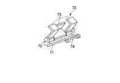
図8は、前記操作部1を把持する把持部22に代って用いることができる、鷲掴み機構70の斜視図である。
前記鷲掴み機構70は、長手方向にコ字状に形成される本体部71と、この本体部71両側部の立上がり片部に亘って架設されるピン72と、このピン72に図示しないコイルばねを介して掛止される複数枚(ここでは3枚)の爪部73とから構成される。By tightening both the
FIG. 8 is a perspective view of a
The
両側の爪部73は互いに同一方向に折曲形成され、真中の爪部73は逆方向に折曲形成される。そして、それぞれの爪部73とピン72との間に掛止されるコイルばねは、爪部73を折曲方向に回動するよう弾性的に付勢している。
前記本体部71の底面部に、本体部71の長手方向と平行する軸方向を備えた軸部74が設けられる。すなわち、前記軸部74は鷲掴み機構70における本体部71とはオフセットした位置にある。The
A
このような鷲掴み機構70の爪部73で操作部1の受け部11を挟持する。オフセットした位置にある軸部74を先に説明した操作部用保持機構12のアーム機構部14先端に保持する。操作部1を軸周りに回転自在とする自由度は、前記軸部74回りの回転で代用する。したがって、実施例1に準じた操作が可能である。
本発明は上述の実施例の形態に限定されるものではなく、他の装置等、本発明の要旨を逸脱しない範囲で種々変形実施できることは勿論である。
つぎに、本出願の他の特徴的な技術事項を下記の通り付記する。
記
(付記項1) 挿入部と操作部とこれらをつなぐ中間部との三体からなる内視鏡と、挿入部を術部に対して位置決め固定する第1の固定手段と、操作部を術空間から外れた位置に保持する第2の固定手段と、を有したことを特徴とする内視鏡システム。
(付記項2) 前記第1の固定手段が、前記内視鏡の延出方向併進自由度と、延出方向軸回り回転自由度の2自由度について固定、解除する第1の制御手段と、その他の4自由度について固定、解除する第2の制御手段とを具備するとともに、前記第2の固定手段が、前記内視鏡の延出方向軸回り回転自由度の1自由度について固定、解除する第3の制御手段と、その他の5自由度について固定、解除する第4の制御手段とを具備する、付記項1記載の内視鏡保持装置。The receiving
The present invention is not limited to the embodiment described above, and it is needless to say that various modifications may be made without departing from the spirit of the present invention, such as other devices.
Next, other characteristic technical matters of the present application are added as follows.
(Additional Item 1) A three-piece endoscope including an insertion portion, an operation portion, and an intermediate portion connecting them, a first fixing means for positioning and fixing the insertion portion with respect to the operation portion, and an operation portion. An endoscope system comprising: a second fixing unit that holds at a position out of space.
(Supplementary Item 2) The first fixing means fixes and releases the two degrees of freedom of the endoscope in the extending direction and the degree of freedom of rotation about the extending direction axis; And a second control means for fixing and releasing the other four degrees of freedom, and the second fixing means is fixed and released for one degree of freedom of rotation about the extending direction axis of the endoscope. The endoscope holding apparatus according to
(付記項3) 前記第1の制御手段と前記第3の制御手段を連動する連動手段を有したことを特徴とする付記項1記載の内視鏡保持装置。
(付記項4) 前記連動手段は、前記第1、第3の制御手段の動作を、時間差を持って動作させることを特徴とする付記項1記載の内視鏡保持装置。
(付記項5) 前記内視鏡の挿入部に、前記第1の固定手段に対して延出方向併進自由度を制限する手段を設けたことを特徴とする付記項1記載の内視鏡保持装置。
(付記項6) 前記内視鏡の操作部に、前記第2の固定手段に対応する円柱形状の被固定手段を設けたことを特徴とする付記項1記載の内視鏡保持装置。
(付記項7) 前記内視鏡の軟性部の柔軟性を拘束して硬性部の代用とし得る拘束手段を具備するとともに前記第1の固定手段が該拘束手段を保持することを特徴とする付記項1から3または付記項6のいずれかに記載の内視鏡保持装置。
(付記項8) 挿入部と、操作部と、これら挿入部と操作部をつなぐ柔性の中間部とからなる軟性内視鏡を保持する内視鏡保持装置において、前記内視鏡の前記操作部を術空間から外れた位置に位置決め保持する第2の保持手段とを具備することを特徴とする内視鏡保持装置。(Additional Item 3) The endoscope holding apparatus according to
(Additional Item 4) The endoscope holding apparatus according to
(Additional Item 5) The endoscope holding device according to
(Additional Item 6) The endoscope holding apparatus according to
(Additional Item 7) An additional note that includes a restraining unit that restrains the flexibility of the flexible portion of the endoscope and can substitute for the hard portion, and the first fixing unit holds the restraining unit.
(Additional Item 8) In an endoscope holding apparatus that holds a flexible endoscope including an insertion portion, an operation portion, and a flexible intermediate portion that connects the insertion portion and the operation portion, the operation portion of the endoscope An endoscope holding apparatus comprising: second holding means for positioning and holding the lens at a position outside the operation space.
5…挿入部、2…中間部、1…操作部、S…内視鏡、12…先端側保持機構(第1の保持手段)、20…操作部用保持機構(第2の保持手段)、15…第1のスイッチ(第1の制御手段)、16…第2のスイッチ(第2の制御手段)、23…第3のスイッチ(第3の制御手段)、24…第4のスイッチ(第4の制御手段)。 DESCRIPTION OF
Claims (3)
Translated fromJapanese前記内視鏡の前記挿入部を術部に対して位置決め保持する第1の保持手段と、
前記内視鏡の前記操作部を術空間から外れた位置に位置決め保持する第2の保持手段とを具備することを特徴とする内視鏡保持装置。In an endoscope holding apparatus that holds a flexible endoscope including an insertion portion, an operation portion, and a flexible intermediate portion that connects the insertion portion and the operation portion.
First holding means for positioning and holding the insertion portion of the endoscope with respect to an operation portion;
An endoscope holding apparatus comprising: a second holding unit that positions and holds the operation unit of the endoscope at a position deviating from an operation space.
前記挿入部を軸方向に沿ってスライド自在とする自由度および、挿入部を軸回りに回転自在とする自由度との2自由度に対して固定保持し、もしくは固定保持を解除する第1の制御手段と、
前記挿入部を前記2自由度を除く自由度について固定保持し、もしくは固定保持を解除する第2の制御手段とを具備することを特徴とする請求項1記載の内視鏡保持装置。The first holding means includes
A first holding unit that fixes or releases fixed holding with respect to two degrees of freedom, that is, a degree of freedom that allows the insertion unit to slide along the axial direction and a degree of freedom that allows the insertion unit to rotate about the axis. Control means;
The endoscope holding apparatus according to claim 1, further comprising: a second control unit configured to fix and hold the insertion portion with respect to the degrees of freedom excluding the two degrees of freedom, or to release the fixed holding.
前記操作部を軸回りに回転自在とする自由度の1自由度のみについて固定保持し、もしくは固定保持を解除する第3の制御手段と、
前記操作部を前記1自由度を除く自由度について固定保持し、もしくは固定保持を解除する第4の制御手段とを具備することを特徴とする請求項1記載の内視鏡保持装置。The second holding means is
A third control means for fixedly holding only one degree of freedom that allows the operation unit to be rotatable about an axis, or for releasing the fixed holding;
The endoscope holding apparatus according to claim 1, further comprising: a fourth control unit configured to fix and hold the operation unit in degrees of freedom excluding the one degree of freedom or to release the fixed hold.
Priority Applications (1)
| Application Number | Priority Date | Filing Date | Title |
|---|---|---|---|
| JP2003413408AJP4402444B2 (en) | 2003-12-11 | 2003-12-11 | Endoscope holding device |
Applications Claiming Priority (1)
| Application Number | Priority Date | Filing Date | Title |
|---|---|---|---|
| JP2003413408AJP4402444B2 (en) | 2003-12-11 | 2003-12-11 | Endoscope holding device |
Publications (2)
| Publication Number | Publication Date |
|---|---|
| JP2005168820Atrue JP2005168820A (en) | 2005-06-30 |
| JP4402444B2 JP4402444B2 (en) | 2010-01-20 |
Family
ID=34733553
Family Applications (1)
| Application Number | Title | Priority Date | Filing Date |
|---|---|---|---|
| JP2003413408AExpired - Fee RelatedJP4402444B2 (en) | 2003-12-11 | 2003-12-11 | Endoscope holding device |
Country Status (1)
| Country | Link |
|---|---|
| JP (1) | JP4402444B2 (en) |
Cited By (1)
| Publication number | Priority date | Publication date | Assignee | Title |
|---|---|---|---|---|
| JP2008154758A (en)* | 2006-12-22 | 2008-07-10 | Olympus Corp | Device for holding insert portion |
Families Citing this family (1)
| Publication number | Priority date | Publication date | Assignee | Title |
|---|---|---|---|---|
| WO2017048194A1 (en) | 2015-09-17 | 2017-03-23 | Endomaster Pte Ltd | Improved flexible robotic endoscopy system |
Citations (7)
| Publication number | Priority date | Publication date | Assignee | Title |
|---|---|---|---|---|
| JPH0622901A (en)* | 1993-06-14 | 1994-02-01 | Olympus Optical Co Ltd | Endoscope holding device |
| JPH0666604U (en)* | 1993-02-25 | 1994-09-20 | オリンパス光学工業株式会社 | Endoscope cover type endoscope system |
| JPH07275190A (en)* | 1994-04-05 | 1995-10-24 | Olympus Optical Co Ltd | Endoscope photographing device |
| JP2000279368A (en)* | 1999-03-31 | 2000-10-10 | Olympus Optical Co Ltd | Endoscope device |
| JP2000316793A (en)* | 1999-05-07 | 2000-11-21 | Asahi Optical Co Ltd | Endoscope holding device |
| JP3081670U (en)* | 2001-05-11 | 2001-11-16 | 松田医科株式会社 | Scope and trocar fixture |
| JP2002165804A (en)* | 2000-09-22 | 2002-06-11 | Mitaka Koki Co Ltd | Medical stand device |
- 2003
- 2003-12-11JPJP2003413408Apatent/JP4402444B2/ennot_activeExpired - Fee Related
Patent Citations (7)
| Publication number | Priority date | Publication date | Assignee | Title |
|---|---|---|---|---|
| JPH0666604U (en)* | 1993-02-25 | 1994-09-20 | オリンパス光学工業株式会社 | Endoscope cover type endoscope system |
| JPH0622901A (en)* | 1993-06-14 | 1994-02-01 | Olympus Optical Co Ltd | Endoscope holding device |
| JPH07275190A (en)* | 1994-04-05 | 1995-10-24 | Olympus Optical Co Ltd | Endoscope photographing device |
| JP2000279368A (en)* | 1999-03-31 | 2000-10-10 | Olympus Optical Co Ltd | Endoscope device |
| JP2000316793A (en)* | 1999-05-07 | 2000-11-21 | Asahi Optical Co Ltd | Endoscope holding device |
| JP2002165804A (en)* | 2000-09-22 | 2002-06-11 | Mitaka Koki Co Ltd | Medical stand device |
| JP3081670U (en)* | 2001-05-11 | 2001-11-16 | 松田医科株式会社 | Scope and trocar fixture |
Cited By (1)
| Publication number | Priority date | Publication date | Assignee | Title |
|---|---|---|---|---|
| JP2008154758A (en)* | 2006-12-22 | 2008-07-10 | Olympus Corp | Device for holding insert portion |
Also Published As
| Publication number | Publication date |
|---|---|
| JP4402444B2 (en) | 2010-01-20 |
Similar Documents
| Publication | Publication Date | Title |
|---|---|---|
| CN111936027B (en) | Arm device | |
| EP2471472B1 (en) | Intra-abdominal cavity operation supporting forceps and medical procedure using intra-abdominal cavity operation supporting forceps | |
| JP4460857B2 (en) | Surgical system | |
| JP4266582B2 (en) | Surgical instruments and surgical systems | |
| US8444547B2 (en) | Medical treatment endoscope | |
| JP5009251B2 (en) | Arthroscopic instruments | |
| US6554766B2 (en) | Endoscope device | |
| JP4856109B2 (en) | Surgical instrument and surgical instrument | |
| US8460276B2 (en) | Manipulation mechanism and medical device instrument | |
| US20190269478A1 (en) | Fixing stand | |
| CN102058437A (en) | Surgical accessory clamp and system method | |
| JP2008307226A (en) | Endoscope system | |
| US20120265007A1 (en) | Endoscope | |
| JP2004180858A (en) | Surgery apparatus | |
| KR101801393B1 (en) | Surgical endoscope and process for exchanging surgical tools in a surgical endoscope | |
| WO2023200981A1 (en) | Endoscopic devices, systems and methods | |
| JPH07328024A (en) | Medical manipulator device | |
| US20190269306A1 (en) | Fixing device for endoscope | |
| JP4402444B2 (en) | Endoscope holding device | |
| WO2018070042A1 (en) | Medical instrument and surgical system | |
| JP2006110053A (en) | Endoscope and endoscope system | |
| JPWO2022198236A5 (en) | ||
| JP2004313319A (en) | Surgical instrument | |
| WO2018070040A1 (en) | Gripping mechanism |
Legal Events
| Date | Code | Title | Description |
|---|---|---|---|
| A621 | Written request for application examination | Free format text:JAPANESE INTERMEDIATE CODE: A621 Effective date:20061018 | |
| A131 | Notification of reasons for refusal | Free format text:JAPANESE INTERMEDIATE CODE: A131 Effective date:20090714 | |
| A521 | Request for written amendment filed | Free format text:JAPANESE INTERMEDIATE CODE: A523 Effective date:20090904 | |
| TRDD | Decision of grant or rejection written | ||
| A01 | Written decision to grant a patent or to grant a registration (utility model) | Free format text:JAPANESE INTERMEDIATE CODE: A01 Effective date:20091006 | |
| A01 | Written decision to grant a patent or to grant a registration (utility model) | Free format text:JAPANESE INTERMEDIATE CODE: A01 | |
| A61 | First payment of annual fees (during grant procedure) | Free format text:JAPANESE INTERMEDIATE CODE: A61 Effective date:20091029 | |
| R151 | Written notification of patent or utility model registration | Ref document number:4402444 Country of ref document:JP Free format text:JAPANESE INTERMEDIATE CODE: R151 | |
| FPAY | Renewal fee payment (event date is renewal date of database) | Free format text:PAYMENT UNTIL: 20121106 Year of fee payment:3 | |
| FPAY | Renewal fee payment (event date is renewal date of database) | Free format text:PAYMENT UNTIL: 20131106 Year of fee payment:4 | |
| S531 | Written request for registration of change of domicile | Free format text:JAPANESE INTERMEDIATE CODE: R313531 | |
| R350 | Written notification of registration of transfer | Free format text:JAPANESE INTERMEDIATE CODE: R350 | |
| R250 | Receipt of annual fees | Free format text:JAPANESE INTERMEDIATE CODE: R250 | |
| R250 | Receipt of annual fees | Free format text:JAPANESE INTERMEDIATE CODE: R250 | |
| R250 | Receipt of annual fees | Free format text:JAPANESE INTERMEDIATE CODE: R250 | |
| R250 | Receipt of annual fees | Free format text:JAPANESE INTERMEDIATE CODE: R250 | |
| LAPS | Cancellation because of no payment of annual fees |