JP2005167986A - Method and apparatus for modulating video signal with data - Google Patents
Method and apparatus for modulating video signal with dataDownload PDFInfo
- Publication number
- JP2005167986A JP2005167986AJP2004290220AJP2004290220AJP2005167986AJP 2005167986 AJP2005167986 AJP 2005167986AJP 2004290220 AJP2004290220 AJP 2004290220AJP 2004290220 AJP2004290220 AJP 2004290220AJP 2005167986 AJP2005167986 AJP 2005167986A
- Authority
- JP
- Japan
- Prior art keywords
- video signal
- auxiliary data
- field
- portable device
- data
- Prior art date
- Legal status (The legal status is an assumption and is not a legal conclusion. Google has not performed a legal analysis and makes no representation as to the accuracy of the status listed.)
- Withdrawn
Links
Images


Classifications
- H—ELECTRICITY
- H04—ELECTRIC COMMUNICATION TECHNIQUE
- H04N—PICTORIAL COMMUNICATION, e.g. TELEVISION
- H04N7/00—Television systems
- H04N7/14—Systems for two-way working
- H—ELECTRICITY
- H04—ELECTRIC COMMUNICATION TECHNIQUE
- H04N—PICTORIAL COMMUNICATION, e.g. TELEVISION
- H04N21/00—Selective content distribution, e.g. interactive television or video on demand [VOD]
- H04N21/40—Client devices specifically adapted for the reception of or interaction with content, e.g. set-top-box [STB]; Operations thereof
- H04N21/41—Structure of client; Structure of client peripherals
- H04N21/414—Specialised client platforms, e.g. receiver in car or embedded in a mobile appliance
- H04N21/41407—Specialised client platforms, e.g. receiver in car or embedded in a mobile appliance embedded in a portable device, e.g. video client on a mobile phone, PDA, laptop
- G—PHYSICS
- G06—COMPUTING OR CALCULATING; COUNTING
- G06Q—INFORMATION AND COMMUNICATION TECHNOLOGY [ICT] SPECIALLY ADAPTED FOR ADMINISTRATIVE, COMMERCIAL, FINANCIAL, MANAGERIAL OR SUPERVISORY PURPOSES; SYSTEMS OR METHODS SPECIALLY ADAPTED FOR ADMINISTRATIVE, COMMERCIAL, FINANCIAL, MANAGERIAL OR SUPERVISORY PURPOSES, NOT OTHERWISE PROVIDED FOR
- G06Q30/00—Commerce
- G06Q30/02—Marketing; Price estimation or determination; Fundraising
- G06Q30/0207—Discounts or incentives, e.g. coupons or rebates
- H—ELECTRICITY
- H04—ELECTRIC COMMUNICATION TECHNIQUE
- H04N—PICTORIAL COMMUNICATION, e.g. TELEVISION
- H04N21/00—Selective content distribution, e.g. interactive television or video on demand [VOD]
- H04N21/20—Servers specifically adapted for the distribution of content, e.g. VOD servers; Operations thereof
- H04N21/23—Processing of content or additional data; Elementary server operations; Server middleware
- H04N21/235—Processing of additional data, e.g. scrambling of additional data or processing content descriptors
- H—ELECTRICITY
- H04—ELECTRIC COMMUNICATION TECHNIQUE
- H04N—PICTORIAL COMMUNICATION, e.g. TELEVISION
- H04N21/00—Selective content distribution, e.g. interactive television or video on demand [VOD]
- H04N21/40—Client devices specifically adapted for the reception of or interaction with content, e.g. set-top-box [STB]; Operations thereof
- H04N21/43—Processing of content or additional data, e.g. demultiplexing additional data from a digital video stream; Elementary client operations, e.g. monitoring of home network or synchronising decoder's clock; Client middleware
- H04N21/435—Processing of additional data, e.g. decrypting of additional data, reconstructing software from modules extracted from the transport stream
- H—ELECTRICITY
- H04—ELECTRIC COMMUNICATION TECHNIQUE
- H04N—PICTORIAL COMMUNICATION, e.g. TELEVISION
- H04N21/00—Selective content distribution, e.g. interactive television or video on demand [VOD]
- H04N21/40—Client devices specifically adapted for the reception of or interaction with content, e.g. set-top-box [STB]; Operations thereof
- H04N21/43—Processing of content or additional data, e.g. demultiplexing additional data from a digital video stream; Elementary client operations, e.g. monitoring of home network or synchronising decoder's clock; Client middleware
- H04N21/436—Interfacing a local distribution network, e.g. communicating with another STB or one or more peripheral devices inside the home
- H04N21/4363—Adapting the video stream to a specific local network, e.g. a Bluetooth® network
- H04N21/43637—Adapting the video stream to a specific local network, e.g. a Bluetooth® network involving a wireless protocol, e.g. Bluetooth, RF or wireless LAN [IEEE 802.11]
- H—ELECTRICITY
- H04—ELECTRIC COMMUNICATION TECHNIQUE
- H04N—PICTORIAL COMMUNICATION, e.g. TELEVISION
- H04N21/00—Selective content distribution, e.g. interactive television or video on demand [VOD]
- H04N21/40—Client devices specifically adapted for the reception of or interaction with content, e.g. set-top-box [STB]; Operations thereof
- H04N21/47—End-user applications
- H04N21/478—Supplemental services, e.g. displaying phone caller identification, shopping application
- H04N21/4784—Supplemental services, e.g. displaying phone caller identification, shopping application receiving rewards
- H—ELECTRICITY
- H04—ELECTRIC COMMUNICATION TECHNIQUE
- H04N—PICTORIAL COMMUNICATION, e.g. TELEVISION
- H04N21/00—Selective content distribution, e.g. interactive television or video on demand [VOD]
- H04N21/80—Generation or processing of content or additional data by content creator independently of the distribution process; Content per se
- H04N21/81—Monomedia components thereof
- H04N21/8166—Monomedia components thereof involving executable data, e.g. software
- H—ELECTRICITY
- H04—ELECTRIC COMMUNICATION TECHNIQUE
- H04N—PICTORIAL COMMUNICATION, e.g. TELEVISION
- H04N7/00—Television systems
- H04N7/025—Systems for the transmission of digital non-picture data, e.g. of text during the active part of a television frame
- H—ELECTRICITY
- H04—ELECTRIC COMMUNICATION TECHNIQUE
- H04N—PICTORIAL COMMUNICATION, e.g. TELEVISION
- H04N7/00—Television systems
- H04N7/08—Systems for the simultaneous or sequential transmission of more than one television signal, e.g. additional information signals, the signals occupying wholly or partially the same frequency band, e.g. by time division
- H04N7/081—Systems for the simultaneous or sequential transmission of more than one television signal, e.g. additional information signals, the signals occupying wholly or partially the same frequency band, e.g. by time division the additional information signals being transmitted by means of a subcarrier
- H—ELECTRICITY
- H04—ELECTRIC COMMUNICATION TECHNIQUE
- H04N—PICTORIAL COMMUNICATION, e.g. TELEVISION
- H04N7/00—Television systems
- H04N7/16—Analogue secrecy systems; Analogue subscription systems
- H04N7/173—Analogue secrecy systems; Analogue subscription systems with two-way working, e.g. subscriber sending a programme selection signal
- H04N7/17309—Transmission or handling of upstream communications
- H04N7/17318—Direct or substantially direct transmission and handling of requests
- H—ELECTRICITY
- H04—ELECTRIC COMMUNICATION TECHNIQUE
- H04N—PICTORIAL COMMUNICATION, e.g. TELEVISION
- H04N21/00—Selective content distribution, e.g. interactive television or video on demand [VOD]
- H04N21/40—Client devices specifically adapted for the reception of or interaction with content, e.g. set-top-box [STB]; Operations thereof
- H04N21/47—End-user applications
- H04N21/478—Supplemental services, e.g. displaying phone caller identification, shopping application
Landscapes
- Engineering & Computer Science (AREA)
- Signal Processing (AREA)
- Multimedia (AREA)
- Business, Economics & Management (AREA)
- Computer Networks & Wireless Communication (AREA)
- Strategic Management (AREA)
- Accounting & Taxation (AREA)
- Development Economics (AREA)
- General Engineering & Computer Science (AREA)
- Finance (AREA)
- Marketing (AREA)
- Theoretical Computer Science (AREA)
- Economics (AREA)
- Software Systems (AREA)
- Physics & Mathematics (AREA)
- General Business, Economics & Management (AREA)
- General Physics & Mathematics (AREA)
- Game Theory and Decision Science (AREA)
- Entrepreneurship & Innovation (AREA)
- Controls And Circuits For Display Device (AREA)
- Television Systems (AREA)
- Two-Way Televisions, Distribution Of Moving Picture Or The Like (AREA)
- Details Of Television Systems (AREA)
- Mobile Radio Communication Systems (AREA)
Abstract
Description
Translated fromJapanese本発明は、インタラクティブな携帯機器に関係し、より具体的には、携帯機器などの受信機で受信して使用するための補助データで映像信号を変調し、信号を受信することによってこれら受信機の利用者に販促機会などの便益を提供するための方法および装置に関係する。 The present invention relates to interactive portable devices, and more specifically, these receivers by modulating a video signal with auxiliary data to be received and used by a receiver such as a portable device and receiving the signal. Relates to a method and apparatus for providing benefits such as promotional opportunities to consumers.
これら携帯機器およびその他の受信機の利用者は、本明細書において集合的に「販促機会」と呼ばれる娯楽、販促、情報の伝達、データ収集、商業上の照合、セキュリティ、教育、取引や販売時点の照合を始めとする目的、およびその他商業的、個人的、エンターテイメント又はアミューズメントの目的のために、補助データを選択的に受信する。
Broughtonらによる「インタラクティブなビデオ方法および装置」と題する米国特許第4,807,031号明細書(以下、「Broughton」という)は、一般的には命令やその他符号化された情報をインタラクティブ機器に帯域内ビデオ放送することに関係する。そこで説明される発明は、一般的にはインタラクティブな教育およびエンターテイメントシステムに関係し、ある実施例では住居内のように、テレビ受信機のある場所に置かれるゲーム機のテレビ番組コントローラーが説明されている。Users of these mobile devices and other receivers are referred to collectively as “promotional opportunities” in this document as entertainment, promotions, information transmission, data collection, commercial verification, security, education, transactions and point-of-sale. Auxiliary data is selectively received for purposes such as collation, and other commercial, personal, entertainment or amusement purposes.
U.S. Pat. No. 4,807,031, entitled “Interactive Video Methods and Devices” by Broughton et al. (Hereinafter “Broughton”) generally provides instructions and other encoded information to interactive devices. Related to in-band video broadcasting. The invention described therein generally relates to an interactive educational and entertainment system, and in one embodiment, describes a television program controller for a gaming machine located at a location of a television receiver, such as in a residence. Yes.
利用者に便益を提供できる制御データを符号化するために、Broughtonは映像信号の輝度又は色変調の新規な方法を開示しており、その方法で、映像信号を制御データで変調する合成映像信号(つまり、変調映像信号)を作る。新規な変調方法は、隣接した水平走査線の輝度/色を交互に上下させて、制御データを含むビデオ副搬送波を作る。
Broughtonでは、映像信号を他のデータと交換することはなく、またデータを映像信号に付随する個別信号として追加することもない。むしろ、映像信号自体を変調して制御データを搬送する。そのため、制御データは映像信号の一部であるか、又は映像信号内に含まれており、その上人の目で認識できない。符号化の方法にはプレビューおよび除去回路も含まれており、適切性、つまりデータ符号化の存在とデータ符号化の除去をそれぞれ確保する。 In Broughton, the video signal is not exchanged with other data, and the data is not added as an individual signal accompanying the video signal. Rather, the video signal itself is modulated to carry control data. Therefore, the control data is a part of the video signal or is included in the video signal and cannot be recognized by the human eye. The encoding method also includes a preview and removal circuit to ensure the adequacy, ie the presence of data encoding and the removal of data encoding, respectively.
制御データは、テレビ放送手段又はビデオディスプレイに接続される録画されたビデオプレーヤーによって伝送される。それから制御データはビデオディスプレイで受信され、そこでビデオディスプレイの少なくとも1つのビデオフィールドを制御データによって変調する。さらに制御データは、番組素材と制御データを判別して制御データを検出する光電子又は無線周波数(RF)検出手段で検出する。検出された制御データはさらに、制御データをインタラクティブ機器で利用できるように再生される。 The control data is transmitted by a recorded video player connected to a television broadcast means or a video display. Control data is then received at the video display, where at least one video field of the video display is modulated with the control data. Further, the control data is detected by a photoelectron or radio frequency (RF) detection means for discriminating program material and control data and detecting the control data. The detected control data is further reproduced so that the control data can be used by the interactive device.
Broughtonの符号化方法を使用して、テレビジョン映像信号のすべてのフィールドで「1」又は「0」を録画できる。NTSC規格では、映像信号は毎秒30フレームが放送されるため、毎秒60フィールドにすると毎秒60ビットのデータ速度になる。しかし、以下詳細に説明するように、この方法を使って確実な連続データを毎秒60ビットにするのは難しいことが多い。 Using the Brownton encoding method, “1” or “0” can be recorded in all fields of the television video signal. In the NTSC standard, video signals are broadcast at 30 frames per second. Therefore, if 60 fields are used per second, the data rate is 60 bits per second. However, as explained in detail below, it is often difficult to achieve reliable continuous data at 60 bits per second using this method.
Broughtonのデータ伝送速度は、比較的遅いということに加えて、処理・再生用の携帯機器やその他の受信機に長い文字列データを伝送するためには、信頼性が低い場合がある。従って、ある出願のBroughtonは、機器に動作をトリガする(つまり、機器がトリガモードで動作する)補助データを捕捉するために、インタラクティブ機器で一般的に使われている。また、Broughtonの補助データ信号は非同期で検出される。これは、インタラクティブ機器やその他の受信機(例えば、デコーダボックス)でのデコード処理が、ディスプレイ機器から受信する映像信号と同期しないためである。さらに、Broughtonのインタラクティブ機器では、ビデオフィールドの始まりが確認できなかった。 In addition to the relatively low data transmission speed of the Broughton, there are cases where the reliability is low in order to transmit long character string data to a portable device for processing / playback or other receivers. Thus, one application, Broughton, is commonly used in interactive equipment to capture auxiliary data that triggers action on the equipment (ie, the equipment operates in trigger mode). Further, the auxiliary data signal of the Brownton is detected asynchronously. This is because the decoding process in the interactive device or other receiver (for example, decoder box) is not synchronized with the video signal received from the display device. In addition, the beginning of the video field could not be confirmed on the interactive device of Broughton.
Broughtonは、好ましくは映像信号に7875Hzの副搬送波を重ね合わせて操作するが、これは15750Hzの水平帰線周波数の半分の速さである。映像信号を副搬送波信号で変調するために、水平線の強度を上げて、フィールドの次の線の強度を下げることによって、7875Hzの副搬送波信号にする。
Broughtonの実施例は、次のとおりである。エンコーダが映像信号の各フィールドを8等分に分割して、各スライスが約2ミリ秒を占め、同じデータビットで符号化される。インタラクティブ機器は8ビットごとに記録と追跡を行い、その後、受信した最新の8ビット(つまり、1バイト)を、インタラクティブ機器のテーブルに記憶された8ビットの所望の組み合わせと比較する。この2つの8ビットのセットが一致すれば、インタラクティブ機器はその後2番目のバイト、それから3番目のバイトの突き合わせへと進む。3つのバイトすべてが一致すれば、インタラクティブ機器での動作がトリガされ、ここに販促機会の視覚又は音声の通知を含めることができる。Broughtonの成功はさておき、当業界には高速でより信頼性の高い、映像信号をデータで変調するための新しい装置および方法へのニーズがある。The Broughton is preferably operated by superimposing a 7875 Hz subcarrier on the video signal, which is half as fast as the horizontal retrace frequency of 15750 Hz. In order to modulate the video signal with the subcarrier signal, the intensity of the horizontal line is increased and the intensity of the next line of the field is decreased to form a 7875 Hz subcarrier signal.
An example of Broughton is as follows. The encoder divides each field of the video signal into 8 equal parts, and each slice occupies about 2 milliseconds and is encoded with the same data bits. The interactive device records and tracks every 8 bits, and then compares the last 8 bits received (ie, 1 byte) with the desired combination of 8 bits stored in the interactive device table. If the two 8-bit sets match, the interactive device then proceeds to match the second byte and then the third byte. If all three bytes match, an action on the interactive device is triggered, which can include a visual or audio notification of the promotional opportunity. Apart from the success of Broughton, there is a need in the industry for new devices and methods for modulating video signals with data that are faster and more reliable.
Broughtonが説明する変調方法の改良が、Ciardulloらによる米国特許第6,094,228号明細書と、Ciardulloらによる米国特許第6,229,572号明細書(本明細書では集合的に「Ciardullo」という)に説明されている。Ciardulloの両特許は、制御データに関係する搬送波信号(つまり補助データ)を、対の線の輝度を反対方向に変えて、映像信号のビジュアル部分に挿入する改良型変調方法を説明している。Broughtonのように映像信号の走査線全体の強度を上下させる代わりに、Ciardulloは擬似雑音シーケンスを利用して、映像信号のフィールドにあるビデオ走査線の一つおき毎に、最初の線系列の部分の強度を上下させ、そこで最初の線と対になる線を逆の擬似雑音シーケンスで変調する。Ciardulloはそれによって、擬似雑音シーケンスを利用して大量の補助データを映像信号内で変調させることができる。BroughtonとCiardulloはともに本発明の譲受人が所有しているが、参照により本明細書に組み込む。 The modification of the modulation method described by Broughton is described in US Pat. No. 6,094,228 by Cirullulo et al. And US Pat. No. 6,229,572 by Cirullullo et al. "). Both Cardullo patents describe an improved modulation method in which a carrier signal related to control data (ie, auxiliary data) is inserted into the visual portion of the video signal with the brightness of the pair of lines changing in the opposite direction. Instead of raising and lowering the intensity of the entire scanning line of the video signal as in the case of Broughton, Cardullo uses a pseudo-noise sequence to generate a portion of the first line series for every other video scanning line in the video signal field. , And then the first pair of lines is modulated with an inverse pseudo-noise sequence. Cardullo can thereby modulate a large amount of auxiliary data in the video signal using a pseudo-noise sequence. Both Brownton and Cardullo are owned by the assignee of the present invention, but are incorporated herein by reference.
本発明の譲受人による過去の成果には、2000年1月21日にEdward J. KoplarとDaniel A. Ciardulloが出願した米国特許願09/489,373号、「接続性を高めたインタラクティブオプティカルカードおよびその他携帯機器」と題する米国実用特許出願(以下、「Koplar I」という)があり、参照により本明細書に組み込む。Koplar Iは、対話型の広告およびゲームなど、販促機会で使用するための様々な方法および装置に関係する。Koplar Iは、携帯機器とデータや信号をやりとりする様々な方法と、販促機会で使用するための装置およびそれを使用する方法を説明している。 Past results by the assignee of the present invention include: Edward J. On January 21, 2000. Koplar and Daniel A. There is US Patent Application No. 09 / 489,373, filed by Cardullo, and a US utility patent application entitled “Interactive Optical Card and Other Portable Devices with Improved Connectivity” (hereinafter referred to as “Koplar I”), which is incorporated herein by reference. Include in the book. Koplar I relates to various methods and devices for use in promotional opportunities, such as interactive advertising and games. Koplar I describes various methods for exchanging data and signals with portable devices, devices for use in promotional opportunities, and methods for using them.
本発明の譲受人による別の特許出願は、2001年4月9日にEdward J. Koplar、Daniel A. Ciardullo、James G. WithersおよびChristopher E. Chuppが出願した米国特許願09/829,223号、「携帯販促機会のための普遍的方法および機器」と題する米国実用特許出願(以下、「Koplar II」という)であり、参照により本明細書に組み込む。Koplar IIは、携帯機器とデータや信号をやりとるするための追加方法と、販促機会を受信するための装置およびそれを使用する方法を説明している。 Another patent application by the assignee of the present invention was issued on April 9, 2001 by Edward J. Koplar, Daniel A. et al. Ciardullo, James G. Withers and Christopher E. et al. US patent application Ser. No. 09 / 829,223 filed by Chupp, a US utility patent application entitled “Universal Methods and Equipment for Mobile Promotional Opportunities” (hereinafter “Koplar II”), which is incorporated herein by reference. Incorporate into. Koplar II describes additional methods for exchanging data and signals with mobile devices, devices for receiving promotional opportunities, and methods for using them.
本発明の譲受人によるさらに別の特許出願は、2002年4月19日にJames G. WithersとAlan G. Maltagliatiが出願した米国特許願10/126,770号、「販促機会を処理するためのRBDS方法および機器」と題する米国特許出願(以下、「Withers」という)であり、参照により本明細書に組み込む。Withers Iは、RBDSシステムを利用した携帯機器への補助データの伝送を始めとして、Koplar IおよびKoplar IIをさらに改良したものを説明している。 Yet another patent application by the assignee of the present invention was filed on April 19, 2002 by James G. Withers and Alan G. US patent application Ser. No. 10 / 126,770, filed by Maltagriati, US patent application entitled “RBDS Methods and Equipment for Processing Promotion Opportunities” (hereinafter “Withers”), incorporated herein by reference. . Withers I describes further improvements to Koplar I and Koplar II, including the transmission of auxiliary data to portable devices using the RBDS system.
本発明の目的上、「携帯機器」という用語は、持ち運びできる特徴をもつインタラクティブ機器で、好ましくは利用者の手のひらや利用者の指の間で持て、又は利用者が手で容易に掴んで扱えることを目的とした手持ち型のインタラクティブ機器を意味する。例として、携帯機器には、スマートカード、携帯電話、個人用の携帯情報端末(PDA)、ゲーム機器、および補助データを受信して処理できるその他の携帯機器が含まれる。 For the purposes of the present invention, the term “portable device” is an interactive device with portable characteristics, preferably held between the palm of the user's palm or the user's finger, or easily grasped and handled by the user. It means a hand-held interactive device for the purpose. By way of example, portable devices include smart cards, cell phones, personal digital assistants (PDAs), gaming devices, and other portable devices that can receive and process auxiliary data.
本発明は、本発明の機能性を組み込むために特注の携帯機器を製造して実施する必要はない。携帯機器には、一般的にメモリーカードを差し込むことができ、場合によっては他の種類の情報を受信するために特別に設計したインターフェースカードを利用できるスロットがあればよい。
フラッシュメモリーカードあるいはストレージカードとも呼ばれることがあるメモリーカードは小型の記憶媒体で、一般的にはフラッシュメモリーを利用して、小型の携帯電子コンピューティング機器で使うための文章、画像、オーディオ、ビデオなどのデータを記憶する。本発明の日現在市販されているメモリーカードには、SDTM(セキュアデジタル)カード、コンパクトフラッシュ(登録商標)カード、メモリースティック(登録商標)カード、マルチメディアカードTM(MMC)、スマートメディア(登録商標)カードがある。メモリーカードは不揮発性固体デバイスで、大きな記憶容量、高速なデータ伝送、高いフレキシビリティ、優れたセキュリティと小型のサイズを兼ね備える。メモリーカードは一般的に携帯機器のスロットに差し込む。The present invention need not be manufactured and implemented with a custom-made portable device to incorporate the functionality of the present invention. A portable device typically has a slot into which a memory card can be inserted, and in some cases a specially designed interface card can be used to receive other types of information.
Memory cards, sometimes called flash memory cards or storage cards, are small storage media that typically use flash memory to write text, images, audio, video, etc. for use in small portable electronic computing devices. Store the data. Memory cards that are commercially available as of the present invention include SDTM (Secure Digital) cards, CompactFlash (registered trademark) cards, Memory Stick (registered trademark) cards, Multimedia CardTM (MMC), SmartMedia (registered trademark). ) There is a card. Memory cards are non-volatile solid state devices that combine large storage capacity, high-speed data transmission, high flexibility, excellent security and small size. A memory card is generally inserted into a slot of a portable device.
スロットは、データの記憶のみを行なうメモリーカードを差し込むために主に使われるが、スロットの機能の中には、それほど制限がなく周辺機器とインターフェースできるものもある。前述の例としては、SDスロットがあり、これは元々携帯機器にフラッシュメモリーを備えるためのものであった。しかし、このスロットはオープンスタンダードで書かれたので、携帯機器で動作するコンピュータソフトウェアを書き込んで、SDスロットを使って接続する周辺機器を制御することができた。このようなスロットとオープンプロトコルをもつ携帯機器を、本明細書では「スロット付き携帯機器」という。本発明の時点では、SDスロットはカメラ、携帯電話、MP3プレーヤー、およびその他携帯機器で利用されている。 Slots are mainly used to insert memory cards that only store data, but some slot functions are not so limited and can interface with peripheral devices. As an example of the above, there is an SD slot, which was originally for providing a flash memory in a portable device. However, since this slot was written in open standards, it was possible to write computer software that runs on a portable device and control peripheral devices to be connected using the SD slot. A portable device having such a slot and an open protocol is referred to as a “portable device with a slot” in this specification. At the time of the present invention, the SD slot is used in cameras, mobile phones, MP3 players, and other portable devices.
インターフェース機器とは、従来スロット付き携帯機器には利用できなかった情報源からデータや他の情報を得ることを主な目的として、カードスロットに差し込むことのできるカードであり、これ以降「インターフェースカード」という。インターフェースカードを製造し利用する(つまり、特注の携帯機器ではなく、スロット付き携帯機器がもつ)最大の利点とは、インターフェースカードが既存のスロット付き携帯機器のリソース(例えば、LCD、インターネットへのアクセス、キーパッドなど)を活かし、それによって製造コストを削減し、このような既存の機器の機能を高めることである。 An interface device is a card that can be inserted into a card slot for the main purpose of obtaining data and other information from information sources that could not be used with portable devices with conventional slots. That's it. The biggest advantage of manufacturing and using an interface card (that is, a slotted mobile device rather than a custom mobile device) is that the interface card has access to existing slotted mobile resources (eg LCD, Internet access) , Keypad, etc.), thereby reducing manufacturing costs and enhancing the functionality of such existing equipment.
SDIO(SD入出力)プロトコルなどのインターフェースプロトコルとは、記憶媒体や周辺機器を適切なスロット(例えば、SDスロット)を使って操作できる様々なスロット付き携帯機器に実装できる規格である。例えば、SDスロットをもち、SDIOプロトコルおよび関連ソフトウェアで有効にされるPDAで、そのSDスロットに差し込めるカメラのような機器を備えるSDカードをもつものは、カメラのような機器を使用して写真を撮ることができ、写真をPDAに記憶するか、又は所定のインターネットの場所に自動的にアップロードする。 An interface protocol such as an SDIO (SD input / output) protocol is a standard that allows a storage medium or a peripheral device to be mounted on various slotted portable devices that can be operated using appropriate slots (for example, SD slots). For example, a PDA that has an SD slot and is enabled by the SDIO protocol and related software that has an SD card with a camera-like device that can be plugged into the SD slot can be photographed using the camera-like device. And store the photos on a PDA or automatically upload them to a predetermined Internet location.
スロット付き携帯機器となるように構成できる別の機器は、任天堂(登録商標)のゲームボーイ(登録商標)というゲーム機である。2002年後半現在、毎日約25,000台の任天堂(登録商標)のゲームボーイアドバンス(登録商標)というゲーム機が販売されており、現在世界中で100,000,000台以上のゲームボーイが使われている。ゲームボーイというゲーム機はSDメモリースロットなどのスロットを装備していないが、X−traFunという社名で運営している会社は、SDスロットを装備したブルートゥースTM対応のゲームボーイカートリッジを開発している。このカートリッジは通信のためのネットワークメカニズムを提供し、スロットにより本発明の機能を備える記憶カードとインターフェースカードを受け入れることができる。Another device that can be configured to be a slotted portable device is a Nintendo (registered trademark) Game Boy (registered trademark) game machine. As of the second half of 2002, about 25,000 Nintendo (registered trademark) Game Boy Advance (registered trademark) game machines are sold every day, and more than 100,000,000 game boys are currently used worldwide. Yes. A game machine called Game Boy does not have a slot such as an SD memory slot, but a company operating under the name X-traFun has developed a Game Boy Cartridge that is equipped with an SD slot and is compatible with Bluetooth™ . This cartridge provides a network mechanism for communication and can accept storage cards and interface cards with the functions of the present invention through slots.
「コンピュータ」という用語も、本明細書ではできる限り広い意味で使われており、ラップトップコンピュータ、コンパクトコンピュータ、パーソナルコンピュータ、携帯電話、ゲーム機器、個人用の携帯情報端末(PDA)、又はその他コンピュータ様の機器、あるいは一以上のマイクロプロセッサ又はデジタルプロセッサを使って、計算やデータ処理、もしくはデータ操作プロセス、又は類似もしくは同様な機能を果たす他の機器を含み、それだけに限定されない。 The term “computer” is also used herein in the broadest possible sense, and is a laptop computer, compact computer, personal computer, mobile phone, gaming device, personal digital assistant (PDA), or other computer. Including, but not limited to, other devices that perform calculations, data processing, or data manipulation processes, or similar or similar functions using one or more microprocessors or digital processors.
本発明は、映像信号をデータで変調するための方法および機器からなる。より具体的には、その方法は、利用者が、放送源からの補助データで変調される映像信号を表示しているディスプレイ機器で、インターフェースカードを差し込んだスロット付き携帯機器を指示することに関わる。
携帯機器は、ディスプレイ機器の垂直帰線信号を使って、映像信号のタイミングを判定するマイクロコントローラと付属回路を有する。映像信号は光検出器を使ってインターフェースカードで受信する。インターフェースカードのマイクロコントローラはさらに、映像信号に補助データが存在するかどうかを判定する。マイクロコントローラは次に、受信した補助データがデータパケットに関係するかどうかを評価する。関係するなら、マイクロコントローラはデータパケットをアセンブルして、利用者に有益なデータを提供し、スロット付き携帯機器の利用者に、有益なデータを受信することにより受ける販促機会やその他の便益を提供する。The present invention comprises a method and apparatus for modulating a video signal with data. More specifically, the method involves a user pointing to a slotted portable device with an interface card inserted in a display device displaying a video signal modulated with auxiliary data from a broadcast source. .
The portable device has a microcontroller and an attached circuit for determining the timing of the video signal using the vertical blanking signal of the display device. The video signal is received by the interface card using a photodetector. The interface card microcontroller further determines whether auxiliary data is present in the video signal. The microcontroller then evaluates whether the received auxiliary data relates to the data packet. If relevant, the microcontroller assembles the data packet to provide the user with useful data and the slotted mobile device user with the promotional opportunities and other benefits received by receiving the useful data. To do.
本発明の好適な実施形態では、スロット付き携帯機器に装着したインターフェースカードと、スロット付き携帯機器で受信したデータを解釈するために実行する適切なソフトウェアを使って、本発明の機能を提供するために、様々な適切な携帯機器を使うことができる。好ましくは、本発明は、SDカードと、任天堂のゲームボーイ、コンパックのiPAQ、およびSDスロットを内蔵するその他のスロット付き携帯機器とインターフェースするSDIOプロトコルを使用する。 In a preferred embodiment of the present invention, the interface card installed in the slotted mobile device and the appropriate software executed to interpret the data received by the slotted mobile device are used to provide the functionality of the present invention. In addition, various suitable portable devices can be used. Preferably, the present invention uses the SDIO protocol to interface with SD cards and Nintendo Gameboys, Compaq iPAQs, and other slotted portable devices that incorporate SD slots.
補助データをインターフェースカード又は携帯機器を使って再生する場合、様々な信号、指示、ディスプレイ表示、又はその他のインタラクティブイベントが、補助データの内容に従って販促機会やその他の便益を利用者に提供する。参照により本明細書に組み込まれるKoplar I、Koplar II、およびWithersで説明される様々なインタラクティブイベントは、本発明とともに使用する携帯機器および方法によって、またそれらと合わせて、互換性をもって使用できる。互換性には、Koplar I、Koplar II、およびWithersの様々な装置および方法のいずれかを選択的に使用することに加えて、本発明の特徴を選択的に使用することも含まれる。 When playing back auxiliary data using an interface card or portable device, various signals, instructions, display displays, or other interactive events provide users with promotional opportunities and other benefits according to the content of the auxiliary data. The various interactive events described in Koplar I, Koplar II, and Withers, which are incorporated herein by reference, can be used interchangeably by and in conjunction with the portable devices and methods used with the present invention. Compatibility includes selective use of any of the various apparatus and methods of Koplar I, Koplar II, and Withers, as well as selective use of features of the present invention.
映像信号をデータで変調するための以下の方法および装置は、Broughtonで以前に開示された方法および装置の改良である。Broughtonは、好ましくは光検出器を使ってデータを携帯機器で光学的に読み取れる、補助データをディスプレイ機器から受信できる通信システムを開示している。
図1を参照すると、映像信号18が信号源10からエンコーダ12に伝送される。映像信号18は好ましくはアナログNTSC映像信号であるが、本発明と互換性のある他の映像信号または映像信号フォーマットでもよい。信号源10は一般的には、ビデオプログラムを内蔵するビデオテープを備える専門仕様のビデオテーププレーヤーであるが、プログラムを内蔵するDVDビデオを備えるカムコーダー又はデジタル多用途ディスク(DVD)プレーヤーを含む他の映像信号源でもよい。エンコーダ12については、以下図5の説明で詳細に記述する。The following method and apparatus for modulating a video signal with data is an improvement over the method and apparatus previously disclosed by Broughton. Brookton discloses a communication system that can receive auxiliary data from a display device, preferably using a photodetector to optically read the data on a portable device.
Referring to FIG. 1, a
オペレータ16はエンコーダ12と対話して、その操作を制御する。好ましくは、オペレータ16は、コンピュータ又は他の電子制御機器を使ってエンコーダ12と対話する人である。しかし、オペレータ16は、自動的にエンコーダ12の操作を指示するコンピュータ又はその他電子制御機器だけでもよい。
搬送波信号20は、エンコーダ12でオペレータ16により映像信号18に選択的に加えられて、映像信号18の中で補助データ21を変調する。搬送波信号20を加える方法では、Broughtonで説明されるように、対の走査線の画素強度を選択的に増減する。しかし、本符号化方法は、Broughtonとは異なり、以下で詳細に説明するように、エンコーダ12が映像信号18の各フィールドを複数のセグメントに分割するので、各セグメントがそれぞれ搬送波信号20で変調でき、最初のフィールドで放送されるデータビットの補数が2番目のフィールドで変調される。選択的に変調するこの方法では、ある実施形態で必要又は望ましい場合には、フィールドの順番(つまり、最初のフィールドと2番目のフィールド)を逆にできることは自明である。好適な実施形態では、本発明はフィールド毎に4等分のセグメントを利用する。The operator 16 interacts with the encoder 12 to control its operation. Preferably, the operator 16 is a person who interacts with the encoder 12 using a computer or other electronic control device. However, the operator 16 may be only a computer or other electronic control device that automatically instructs the operation of the encoder 12.
The
映像信号18を変調する際、エンコーダ12は、映像信号18と補助データ21とからなる変調映像信号22(つまり、合成映像信号)を出力する。変調映像信号22はさらに、番組を視聴するエンドユーザーに配信するために、放送源14に供給される。放送源14は好ましくは番組を放送するテレビ放送局であるが、他の放送映像源および複数のエンドユーザーに提供するDVD媒体やビデオテープを含むその他メディアソースでもよい。 When modulating the
図2および3を参照すると、放送源14は変調映像信号22をディスプレイ機器26に供給する。ディスプレイ機器26の例としては、テレビ画面、ビデオモニターやその他ビデオディスプレイ、映画のスクリーン、コンピュータモニター、またはテレビ送信機、ビデオテープ、ストリーミングビデオサーバー、DVDのような画像コンテンツ源のコンピュータ化ディスプレイ表示などの適切な信号源から、アナログもしくはデジタルビデオ又はビデオ表示信号を受信できるビデオ変換ディスプレイやビデオのようなディスプレイが代表的である。ここでの目的上、ディスプレイ機器26は受像管又はその他従来型のテレビジョンディスプレイもしくはモニターである(複数又は単一ビーム型のプロジェクターディスプレイを含めてもよい)。 With reference to FIGS. 2 and 3, the
ディスプレイ機器26は大まかにいうと映像信号18を表示するビデオディスプレイを表すが、可視できる形態の画像情報だけでなく、実質的に透過モードの補助情報(つまり、データ)も提供できるあらゆる種類の電子銃、アクティブアレイ又はパッシブアレイのディスプレイ機器でもよい。ディスプレイ機器26はまた、コンピュータモニター又はディスプレイ、およびディスプレイ機器26の一部又はコンピュータウィンドウとして特徴付けることもできる。ディスプレイ機器26は、高解像度テレビジョン、デジタルテレビジョン、又はその他デジタルビデオ表示機器でもよい。ディスプレイ機器26の大きさは様々でよく、ソニー(登録商標)のウォッチマン(登録商標)のように小型でも、映画のスクリーンやソニージャンボトロン(登録商標)にように大型でもよい。ディスプレイ機器26によって放送源14から受信できる映像信号18には、マイクロ波リレー、衛星再伝送又はケーブル、ダウンロード可能なもしくは視聴可能なコンピュータビデオ放送のストリーミングおよびその他の形態によって送られるもの、有線もしくは無線の方法によって一般に利用できるものが含まれる。
変調映像信号22はディスプレイ機器26上に表示される。スロット付き携帯機器29は、インタラクティブカード60に搭載する光検出器62を使って、変調映像信号22を光学的に受信する。スロット付き携帯機器29は、スマートカード、携帯電話、PDA、ゲーム機、又はスロット66を有するその他手のひらサイズの機器など、あらゆる種類の手で扱うことのできる機器の形態でよい。スロット付き携帯機器29は、ディスプレイ機器26の近辺で、一般的には同じ室内で、利用者の手のひら又は指の間に保持してもよいし、また必要ならば、光検出器62が、ディスプレイ機器26からの変調映像信号22のビジュアル表示から、光を光学的に受信できるように方向付けてもよい。あるいは、光検出器62、インターフェースカード60、データデコーダ72、スロット付き携帯機器29は、Koplar Iで使用したようなスロットなしの携帯機器28に連結できることは自明である。 The modulated
本発明の好適な実施形態では、PDA、ゲーム機、又は携帯電話などのスロット付き携帯機器29にはスロット66が備えられ、インターフェースプロトコル68を実行するソフトウェアおよび/又は他の電子機器が内蔵される。本発明は、機器29がそのプロトコル(つまり、「オープンプロトコル」)をカード60とスロット66で拡張的に使用できるインターフェースプロトコル68を使うのであれば、様々なインターフェースカード60とスロット66で使うことができる。好ましくは、スロット66はSDスロットであり、インターフェースプロトコル68はSDIOプロトコルである。インターフェースプロトコル68を動作させるインターフェースカード60も、スロット付き携帯機器29に差し込まれて、機器29がソフトウェアを実行してカード60から受け取るデータを解釈し、インターフェースプロトコル68を使ってそれを機器29に伝える。 In a preferred embodiment of the present invention, a slotted
図3で詳細に示すように、映像信号20と補助データ21から構成される変調映像信号22は、ディスプレイ機器26から伝送されて、インターフェースカード60の光検出器62で検出される。その後、受信した変調映像信号22は、インターフェースカード60上にあるデータデコーダ72で復号化される。復号化された補助データ21は、インターフェースプロトコル68を使って、スロット付き携帯機器29に渡される。スロット付き携帯機器29は補助データ21を利用して、補助データ21の受け取りに基づいて便益や販促機会を利用者に提供する。販促機会は、Koplar Iで説明されるように、オプションのワイヤレスインターネットアクセス70を使って補う又は取得してもよい。 As shown in detail in FIG. 3, the modulated
スロット付き携帯機器29は、好ましくはワイヤレスインターネットアクセス70を利用して、インターネットを介して販促機会を提供および/又は補う。ワイヤレスインターネットアクセスの好適なプロトコルは、ブルートゥースの利用である。ブルートゥースは、RFデータを2.4GHz周波数で、スロット付き携帯機器29とインターネットに接続されるトランシーバーとの間を指定の形で受け渡す手段を提供する。インターネットネットワークの業界において、有線および無線のインターネットを提供する他の手段も、Wifi 802.11を含む本発明とともに使用できることは理解されるであろう。 The slotted
本発明の別の実施形態として、光検出器62に追加して、又は光検出器62の代用として、インターフェースカード60は、放送源14が、RFなどの信号伝送の業界において周知の様々な方法によって、変調映像信号を復調し、補助データ21を伝送するデコーダボックスであるときなど、RF受信機を使用するなどの他の手段によって、変調映像信号22又は補助データ21を受信することができる。 As another embodiment of the present invention, in addition to or as a substitute for the
また、望ましい場合には、データ記憶装置(図示せず)をインターフェースカード60に追加して、補助データ21又は販促機会を後で呼戻すために記憶することができる。アプリケーションによって、インターフェースカード60に大量のスペースを設けることにより莫大な量のデータを記憶し、後で検索できるようにすることが望ましいことは自明である。 Also, if desired, a data storage device (not shown) can be added to the
図2の光検出の別の態様として、図4は補助データ21の電気検出を示す。放送源14が変調映像信号22をデコーダ13に供給する。以下詳細に取り上げるように、デコーダ13は、補助データ21が変調映像信号22に存在するかどうかを判定することによって、データデコーダ72と同様に動作するが、伝送機器24とビデオ出力も内蔵しているので、変調映像信号22をディスプレイ機器26に供給する。補助データ21が伝送機器24に供給されて、そこから、光検出器62ではなく、RF受信機、赤外線接続やコンピュータ同様の接続などの非光学受信機64で、情報をスロットのない携帯機器28に転送する。変調映像信号22は、変更されずにデコーダ13を通ってビデオ出力を出し、利用者がビデオプログラムを視聴できるようにディスプレイ機器26に表示される。補助データ21の受信時には、スロットのない携帯機器28は、利用者に便益や販促機会を提供する。 As another aspect of the light detection of FIG. 2, FIG. 4 shows electrical detection of the
前述の別の態様として、非光学受信機64は、スロット付き携帯機器29がスロットのない携帯機器28に代わって、前述の説明と一致する方法で動作するように、インターフェースカード60に実装できる。
図5のエンコーダ12は、映像信号18を信号源10から受信して、それをマイクロコントローラ36に伝えるデジタルビデオ入力30を内蔵する。しかし、エンコーダ12はアナログビデオ入力32とアナログ/デジタル変換器34を介して、アナログ映像信号18を受信することもできる。アナログ/デジタル変換器34は、周知の技術に従って、アナログ映像信号18をデジタル化して、マイクロコントローラ36に送信できるようにする。As another aspect described above, the non-optical receiver 64 can be implemented in the
The encoder 12 of FIG. 5 includes a
マイクロコントローラ36はキャリアプレゼンス38に電気接続されて、それが、オペレータの指示により、エンコーダ12が搬送波信号20を映像信号18に挿入する場所、時期、および強度のタイミングを、マイクロコントローラ36に提供する。好ましくは、前述の指示は、シリアルポートを介してキャリアプレゼンス38によってオペレータ16から受け取る。しかし、電子工学の業界において、ユニバーサルシリアルバス(UBS)、「ファイヤワイヤー」プロトコル(IEEE 1394)、および様々な無線プロトコルを介するなど、エンコーダ12の他の機器との相互接続が考えられることは自明である。代替の実施形態において、キャリアプレゼンス38は、オペレータ16がエンコーダ12に直接インターフェースできるようなオペレータインターフェースでもよい。 The
マイクロコントローラ36が映像信号18とキャリアプレゼンス38からの情報を受け取ると、ソフトウェア50がエンコーダ12のその後の動作を管理し、記憶装置40に映像信号18の色情報を記憶するようマイクロコントローラ36に指示を出す。エンコーダの電子回路42はソフトウェア50の指示で、好ましくは以下詳細に説明するBroughtonと本発明の方法を利用して、搬送信号20を映像信号18の輝度に変調し、それによって変調映像信号22を生成する。生成された変調映像信号22はさらに、デジタルビデオ出力44によってエンコーダ12からデジタル方式で送られ、又は生成されたデジタル信号をデジタル/アナログ変換器46で変換し、変調映像信号22をアナログビデオ出力48で出力することによって、アナログ方式で送られる。 When the
マイクロコントローラ36は、本発明の様々な処理と入出力を管理する複数のプロセッサから構成できるが、好ましくは1つのプロセッサから構成する。また、エンコーダ12が使用する特別な電子機器やソフトウェアは、スタンドアローン型機器ではなく、その技術が既存の機器に内蔵されている場合には、別のものでもよい。エンコーダ12は、様々なコンポーネントが互いに互換性をもって使用できるため、ハードウェアおよびソフトウェアを様々な範囲で具備することができる。 The
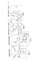
図6には、データデコーダ32のマイクロコントローラ100とデバイス回路102の好適な実施形態の概要を示す。デバイス回路102は、アナログプレフィルタ104と、垂直検出/信号強度回路106と、補助データ検出器108とから構成され、そのすべてが相互に、また図示するマイクロコントローラ100と連動する。
図7を参照すると、回路を正確にデジタル化するためのアナログプレフィルタ104の好適な実施形態は、まず電流電圧変換器300を具備する。電流電圧変換器300は、まず光検出器D200を具備し、これがディスプレイ機器26からの映像信号18を光学的に読み取って、電流を電流電圧変換器300に出力する。その後、電流電圧変換器300は、光検出器D200が検出した電流を電圧に変換する。電圧変換器300の回路はさらに、3つの抵抗器R200、R201、R202と、3つのコンデンサC200、C201、C202と、演算増幅器U200と、電圧VAおよびVCCとを具備し、そのすべてが図示するように連動する。FIG. 6 shows an overview of a preferred embodiment of the
Referring to FIG. 7, a preferred embodiment of the
アナログプレフィルタ104の自動利得制御装置310の部分が、フィードバック回路の抵抗を変えることによって、映像信号18を増幅する。回路に供給される利得の量は、マイクロコントローラ100で制御される。自動利得制御装置310は、ディスプレイ機器26から受信する距離と強度が変わるため、インターフェースカード60と一緒に使う。従って、映像信号18の強度が低いとき、利得を追加して、映像信号18を読み取りやすくできるようにすることが望ましい。そのため、本発明は信号強度を測定し、利得を下げるか上げるかを判断する。自動利得制御装置310のコンポーネントには、抵抗器R203、R208、R209と、コンデンサC212と、電圧VAおよびVCCと、演算増幅器U400Cと、デジタルポテンショメーターU204とがあり、そのすべてが図示するように連動する。 The
映像信号18は、自動利得制御装置310から遮断周波数80KHzの低域フィルタ320へと渡る。この回路は、予め設定したレベル(つまり、80キロヘルツ)を超えるすべての周波数を排除することによって、信号から高周波雑音を除く低域フィルタとなる。遮断周波数80KHzの低域フィルタ320のコンポーネントには、抵抗器R210、R204、R205と、コンデンサC203、C204、C206と、電圧VAおよびVCCと、演算増幅器U201とがあり、そのすべてが図示するように連動する。 The
映像信号18はまた、遮断周波数80KHzの低域フィルタ320から遮断周波数7KHzの高域フィルタ330に渡る。遮断周波数7KHzの高域フィルタ330は、所望しない信号を切り捨てて、7KHz未満の信号を一掃する。遮断周波数7KHzの高域フィルタ330のコンポーネントには、抵抗器R206およびR207と、コンデンサC207、C208、C209、C210、C211と、電圧VAおよびVCCと、演算増幅器U201とがあり、そのすべてが図示するように連動する。信号が遮断周波数7KHzの高域フィルタ330を通過すると、映像信号18のプレフィルタリングが完了する。 The
ここで図8を参照すると、好適な実施形態の垂直検出/信号強度回路106の回路が、信号強度検出器340とアナログ垂直同期350とを具備する。信号強度検出器340はまず、映像信号18を分極する整流器D300を具備する。その後、映像信号18は、抵抗器R306およびR307と、電圧VAと、演算増幅器U300Bとから構成されるバッファに転移して、信号を逆にする。この回路の最後の部分は積分器であるが、これは映像信号18の強度を測定し、抵抗器R308と、コンデンサR305と、電圧VAと、演算増幅器U300Dとから構成され、そのすべてが図示するように連動する。積分器の出力は信号SSRES1であり、マイクロコントローラ100で受信され、その後、マイクロコントローラ100は、信号強度積分器をリセットする。 Referring now to FIG. 8, the circuit of the preferred embodiment vertical detection /
アナログ垂直同期350への信号は、遮断周波数80KHzの低域フィルタ320から渡される。アナログ垂直同期350は、補助データ21からのデータビットの読み取り値を同期するために使用する、所望の垂直同期信号を生成する。回路の最初の部分は利得増幅器で、これが信号を取得して、抵抗器R300およびR301と、コンデンサC300と、電圧VAと、ゲートU300Dとを使って、信号を逆にする。回路の2番目の部分は小さなフィルタリング段階をおく。抵抗器R302およびR303とコンデンサC301が、信号から高いスパイクをフィルタリングする。 The signal to the analog
その後、信号は、バッファとして機能する二重反転であるシュミットトリガインバーターU302AおよびU302Dで処理される。シュミットトリガの性質により、電圧スパイクが信号から取り除かれる。その後、信号はフリップフロップ74HD74をトリガする。フリップフロップ74HD74の出力が、555タイマー555をトリガし、これを使って一定間隔のパルスを生成する。各パルスの間、555タイマー555が何度トリガを受けても、タイムアウトするまで不要なパルスを生成しない。抵抗器R305を使って時定数を調整することができ、それによってパルスは広くすることも狭くすることもできる。マイクロコントローラ100がパルスを検出してから、さらに垂直帰線期間(つまり、16.67ミリ秒)の間待って、もう一度パルスを検出すると、垂直同期信号で固定されていることが分かる。 The signal is then processed by Schmitt trigger inverters U302A and U302D, which are double inversions that function as buffers. Due to the nature of the Schmitt trigger, voltage spikes are removed from the signal. The signal then triggers flip-flop 74HD74. The output of flip-flop 74HD74 triggers 555 timer 555, which is used to generate regularly spaced pulses. During each pulse, no matter how many times the 555 timer 555 is triggered, an unnecessary pulse is not generated until it times out. Resistor R305 can be used to adjust the time constant so that the pulse can be widened or narrowed. When the
図9を参照して、プレフィルタ信号が水平ノッチフィルタ360に渡され、ノッチフィルタが変調映像信号22から水平線走査速度(つまり、15570KHz)で映像信号18を取り除き、補助データ21の読み取り値を妨害しないようにする。その後、VEIL周波数370でカットオフする低域フィルタは追加フィルタリングのために使われ、8キロヘルツより高い信号を確実に切り捨てる。それから、信号を帯域フィルタ380に渡すが、これは8キロヘルツ近傍をフィルタリングする別の段階である。信号はその後、1の利得をもつ積分器として機能する信号整流器390を通過する。最後に、信号は、電圧を測定することによって信号強度を測定するVEIL信号エネルギー積分器400を通る。前述の回路は、多数の抵抗器R400〜R413、コンデンサC400〜410、電圧VAおよびVCC、演算増幅器U400A、U400B、U400D、U401D、U401C、U401Bから構成され、そのすべてが図示するように連動する。 Referring to FIG. 9, the prefilter signal is passed to the
図10に図示するように、光検出器62を備えるスロットのない携帯機器28において、スロット付き携帯機器29、データデコーダ72、インターフェースカード60の組み合わせの最初のバーションで使用されるであろうマイクロコントローラ100と付属回路は、まず4個のバッテリBC500、BC501、BC502、BC503から構成される電源を具備する。各バッテリは1.5ボルトで、電力は電圧調整器U501に供給される。電圧調整器U501は、D501から安定した5ボルトの電力をマイクロコントローラ100に供給する。VCCとVAも電圧調整器U501によって供給され、そこで分圧器によって、VAは2.5ボルトに、VCCは5ボルトになる。VCCはバッテリ電圧を供給するダイオードD501から供給されることになる。 As shown in FIG. 10, in a slotless
ダイオードD501は、電圧需要を減らせるように、マイクロコントローラ100をスリープモードにすることができる。マイクロコントローラ100がスリープ状態になりたいとき、電圧調整器U501を遮断して、スリープモードになることができる。デュアルアナログスイッチMAX323を使って、信号強度積分器とVEIL信号強度積分器の両方を、マイクロコントローラ100からリセットする。 The diode D501 can put the
この実施形態に存在する別のコンポーネントは、スピーカーSPK1、トランジスタQ504、視覚表示装置U503、スイッチS500、S501、S502、S503、S504、インターフェースRS232であり、このすべてが図示するように連動し、その使用は本発明と、Koplar I、Koplar IIおよびWithersで説明する携帯機器に一致する。 Other components present in this embodiment are speaker SPK1, transistor Q504, visual display U503, switches S500, S501, S502, S503, S504, interface RS232, all of which work together as shown and are used Is consistent with the present invention and the portable devices described in Koplar I, Koplar II and Withers.
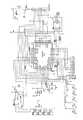
本発明の別の好適な態様では、図11のマイクロコントローラ100がインターフェースカード60に実装されて図示されている。マイクロコントローラ100はこの好適な実施形態では、2つの別々のマイクロコントローラU500とU503から構成されるように示されており、そのうちマイクロコントローラU500は、光検出や、補助データ21が映像信号18に存在するかどうかの判定など、図10で説明するようにマイクロコントローラ100の動作を制御し、マイクロコントローラU503は、スロット66とのインターフェースを管理する(つまり、SDIOコネクタJ501)。SDIOコネクタJ501は、以下に説明するように、インターフェースカード60と通信する。マイクロコントローラU503はさらに、回路の光学部分とSD部分との通信も制御する。好ましくは、マイクロコントローラU503は8MHzで実行し、マイクロコントローラU500は4MHzで実行する。 In another preferred aspect of the present invention, the
ポートRS232は、適切な補助データをインターフェースカード60で確実に受信して変調するようにシステムをデバックするためなど、様々な実施形態で任意に内蔵できるコンピュータインターフェースである。集積回路Max232は、インターフェースカード60を、コンピュータポートRS232を介して通信できるようにするので、インターフェースカード60は、デバック目的などのために、コンピュータと直接対話できる。 Port RS232 is a computer interface that can optionally be incorporated in various embodiments, such as for debugging the system to ensure that appropriate auxiliary data is received and modulated by
好適な実施形態では、電力がスロット66から供給されるので、インターフェースカード60に電源は必要ない。ただし、チャージポンプU504が、スロット66から受け取る3ボルトを、インターフェースカード60に適切に電力を流せるように5ボルトに変える。図11に図示する他のコンポーネントは、図10で使用するとおりである。
映像信号18を補助データ21で変調するための方法の好適な実施形態を、図12に示す。最初の工程1000では、利用者は、スロット付き携帯機器29などの受信機を、変調映像信号28を捕捉するために、ディスプレイ機器26に向けるか、又はディスプレイ機器26に連結して接続する。その後、第2の工程1100で、映像信号18を、インターフェースカード60の光検出器30によって、ディスプレイ機器26から捕捉する。マイクロコントローラ100とデバイス回路104は、第3の工程1200で受信する映像信号18を増幅、フィルタリング、整形する。In the preferred embodiment, no power is required for the
A preferred embodiment of a method for modulating
さらに図12を参照して、第4の工程1300で、マイクロコントローラ100は、補助データ21が映像信号18に存在するかどうか(つまり、映像信号18が変調映像信号22に変調されているかどうか)を判定する。映像信号18に補助データ21が存在しない場合、方法は第2工程1100に戻って、もう一度変調映像信号22の捕捉を試みる。第4工程1300で、マイクロコントローラ100が補助データ21の存在を確認したら、方法は第5工程1400に進み、マイクロコントローラ100は、インターフェースカード60が完全なデータパケット112を受信しているかどうかを判定する。補助データ21がデータパケット112の形になっていない場合、又はそれ以外で使用できない場合、補助データ21は廃棄されて、方法は第2工程1100に戻る。 Still referring to FIG. 12, in a
補助データ21がデータパケット112の形になっている場合、第6工程1600で、マイクロコントローラ100は、インターフェースカード60が受信すると予想するパケットの総数114と、ちょうど受信したデータパケット112のデータパケット数116の同一性を判定する。インターフェースカード60が受信するパケットの総数114が1ならば、マイクロコントローラ100はさらに、スロット付き携帯機器29の利用者に対して、第9工程1800で開示する所望の補助データ21をすべて受信する結果としての便益(例、販促機会)を提供するために、必要な措置をとる。パケットの総数114が1よりも大きい場合、マイクロコントローラ100は、第8工程1700に進み、それによってマイクロコントローラ100は、各データパケット数116に対応するすべてのデータパケット112を捕捉しているかどうかを判定する。 If the
第8工程1700で、すべてのデータパケット112が捕捉されていなければ、インターフェースカード60は第2工程1100に戻って、抜けているデータパケット112の捕捉を試みる。すべてのデータパケット112が捕捉されたら、スロット付き携帯機器29は、第9工程1800に従って、利用者に販促機会を提供することになる。第9工程1800で、スロット付き携帯機器29の利用者は、文字情報、懸賞、割引券、ゲーム、特別な利用権などを含むことができる販促機会やその他の便益を受信する。その後、本発明の方法は、最終工程1900で終了する。 If all data packets 112 have not been captured in the eighth step 1700, the
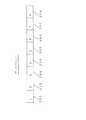
前述の方法の間、映像信号20のフィールドは、Broughtonとは違った形で符号化される。Broughtonの方法は、フィールド200の各部分を同一のビットで符号化することを必要とする。図13に図示するように、フィールド200の各スライス200a〜hはビット「1」を含む。
本発明では、フレーム220のフィールド210aと210bは、補間ビットで符号化する。このように、論理「1」は2つのフィールド210aと210bで「1 0」として符号化され、論理「0」は2つのフィールド210aと210bで「0 1」として符号化される。インターフェースカード60がビットを受信すると、2つの連続したフィールド210aと210bの強度の結果を引き算して、フィールドの比較を行なう。この方法で、毎秒30ビットという信頼できるデータ速度が生まれる。During the above method, the field of the
In the present invention, fields 210a and 210b of
図13に図示するように、すべてのフィールド210を、各部分がそれぞれ独自のビットをもつ複数のセグメントに分割して、本発明の速度を上げる。好ましくは、各フィールド210を4等分に分割して、各部分が互いに等しくずれた位置になるようにする。このように、フィールド210aと210bの分割は、4つのデータビットが「1 0 1 1」と符号化された状態で図13のようになる。フィールドを分割するというこの方法で、毎秒120ビットの信頼できる速度が生じる。 As illustrated in FIG. 13, all
図12の第2工程の間に、前述の方法が機能するためには、マイクロコントローラ100が、すべてのビットをきちんと得られるように、復号中にフィールド210aと210bが始まる場所を判定する必要がある。第1の実施形態では、データデコーダ32は、映像信号20の垂直帰線期間を探して、それに同期させることによって、その正確なタイミングを得る。 In order for the method described above to work during the second step of FIG. 12, the
図14を参照して、マイクロコントローラ100はまず、ディスプレイ機器26に真っ黒(つまり、ビデオがない)に表示されるため、画像の垂直リフレッシュが生じていることを示す垂直帰線信号となる画像部分を探す。その後、マイクロコントローラ100は、別の垂直リフレッシュが生じるだけの時間(つまり、16.67ミリ秒)を待つ。マイクロコントローラ100が真っ黒な2つの連続する領域を読み取り、それが16.67ミリ秒離れていると、マイクロコントローラ100は、垂直帰線信号を固定しているという考えのもとに働き、垂直帰線信号の始まりから2ミリ秒という好適な変位で、データパケット112を読み取って記録し続ける。前述の同期プロセスの間に、データデコーダ32が第1および第2の黒領域を検出しない場合、前に探したところから16.67ミリ秒離れた黒領域を探すことによって、同期を試み続ける。 Referring to FIG. 14,
垂直帰線信号が同期して、データデコーダ32が有効なデータをうまく読み取ったら、データデコーダ32はその時映像信号18と同期していることになり、一次的に垂直帰線信号の探索を止める。本発明における映像信号18の固定の第1の好適な実施形態では、データデコーダ32は数秒間垂直帰線信号を固定し、その後それを解放して、同期プロセスを再び開始する。マイクロコントローラ100のタイミングが完全には正確でないために、垂直帰線信号の同期が数秒後にドリフトし、有効な補助データ21の検出がさらに難しくなるため、この実施形態においては、本発明の再検出および再同期が好ましい。 If the vertical blanking signal is synchronized and the
第2の好適な実施形態では、補助データ21の始まりは、同期を探すことによって判定する。データデコーダ32は、A5など、マーカー又はプリアンブルとして機能するデータパケット112の最初のデータビットを探す。データデコーダ32が、マーカーを捕捉しようとしながら、ディスプレイ機器26全体を非常にゆっくりドリフトした後、データデコーダ32は、データパケット112の始まりであるかのように動作して、連続的に様々なビットを読み取る。データビットは連続的に読み取られて、レジスタの左側に移り、データデコーダ32がまずA5バイトを受信できるようにする。有効なデータパケット112が受信されたら、データデコーダ32は完全に同期され、連続的なデータパケット112の読み取りを続けることができる。データデコーダ32は、データパケット112のCRCバイトを点検することによって、有効なデータパケット112を確保する。 In the second preferred embodiment, the start of
補助データ21は、好ましくは8バイト(つまり、64ビット)長のデータパケット112で、マイクロコントローラ32によって読み取られる。図14に図示するように、データパケット112の好適な実施形態はまず、データパケット112の始まりと一致するプリアンブルを含む第1のバイト250を備える。第2バイト252は、送られるパケットの総数25に対するデータパケット数26(つまり、パケットは5つのうちの2つ)を含む。次の5つのバイト254、256、258、260、262(つまり、バイト3〜7)は実際のデータを含み、これはデータ圧縮の当業者には容易に理解されるように、圧縮できる。最後のバイト264には、受信したデータバイト250〜262が信号源から伝送されたものと正確に一致したことを保証する巡回冗長検査(CRC)が含まれる。 The
メッセージ118のデータパケット112は、コンピュータネットワークの業界では理解されるように、一般的には放送源14から複数回送られる。好適な実施形態のメッセージ118は、最高16のデータパケット112を含むことができる。データパケット112は、スロット付き携帯機器29やその他の受信機で、どのような順番でも受信することができ、スロット付き携帯機器29がそれ以前に捕捉に成功したデータパケット112は無視される。すべてのデータパケット112がスロット付き携帯機器29で正確に受信されると、全体のメッセージ118は復号化に成功したことを宣言され、スロット付き携帯機器29は、便益や一以上のその他の販促機会を利用者に提供することによって、適切な行動をとる。 The data packet 112 of the message 118 is typically sent multiple times from the
以上、発明の具体的な実施形態を例示して説明してきたが、発明の精神と範囲を逸脱することなく、そこに様々な変更を行なえることは自明である。そのため、発明は明細書によって制限されるものではなく、本発明の範囲は添付の請求項によってのみ制限するよう意図される。 Although specific embodiments of the invention have been described above as examples, it is obvious that various modifications can be made without departing from the spirit and scope of the invention. As such, the invention is not limited by the specification and the scope of the present invention is intended to be limited only by the appended claims.
10 信号源
12 エンコーダ
14 放送源
16 オペレータ
18 映像信号
20 搬送信号
21 補助データ
22 変調映像信号
24 伝送機器
26 ディスプレイ機器
28 携帯機器
29 スロット付き携帯機器
30 デジタルビデオ入力
32 アナログビデオ入力
34 ビデオデコーダ
36 プロセッサ
38 キャリアプレゼンス
40 記憶装置
42 エンコーダの電子回路
44 デジタルビデオ出力
46 デジタル-アナログ変換器
48 アナログビデオ出力
50 エンコーダのソフトウェア
60 インターフェースカード
62 光検出器
64 非光学受信機
68 インターフェースプロトコル
70 ワイヤレスインターネットアクセス
72 データデコーダ
100 マイクロコントローラ
104 アナログプレフィルタ
106 垂直検出/信号強度
108 VEIL検出器
300 電流電圧変換器
310 自動利得制御装置
320 遮断周波数80KHzの低域フィルタ
330 遮断周波数7KHzの高域フィルタ
360 水平ノッチフィルタ
370 低域フィルタw/VEIL周波数でカットオフ
380 VEIL帯域フィルタ1
390 信号整流器
400 VEIL信号エネルギー積分器10 Signal source 12
390
Claims (26)
Translated fromJapanese補助データを前記変調映像信号を介してスロット付き携帯機器に伝送するための手段を具備する放送源と、
前記スロットを介して携帯機器に電子的に連結され、カードマイクロコントローラと、前記放送源から変調映像信号を受信するためにカードマイクロコントローラに電子的に連結される受信機と、前記変調映像信号を復調して補助データを再生し、補助データをインターフェースプロトコルを介して携帯機器に転送するために、カードマイクロコントローラと受信機に電子的に連結される回路とを具備するインターフェース機器と、
前記インターフェース機器からインターフェースプロトコルを介して受信する信号補助データを処理するためのマイクロコントローラを具備するスロット付きの携帯機器と
からなることを特徴とするシステム。A system for transmitting auxiliary data in a modulated video signal from a broadcast source to a portable device with a slot.
A broadcast source comprising means for transmitting auxiliary data to the slotted portable device via the modulated video signal;
A card microcontroller, a receiver electronically coupled to the card microcontroller to receive the modulated video signal from the broadcast source, and the modulated video signal; An interface device comprising a card microcontroller and circuitry electronically coupled to the receiver for demodulating and reproducing auxiliary data and transferring the auxiliary data to the portable device via an interface protocol;
A slotted portable device comprising a microcontroller for processing signal auxiliary data received from the interface device via an interface protocol.
補助データを前記変調映像信号を介してスロット付き携帯機器に伝送するための手段を具備する放送源と、
前記スロットを介して携帯機器に電子的に連結され、カードマイクロコントローラと、前記放送源から変調映像信号を受信するためにカードマイクロコントローラに電子的に連結される受信機と、前記変調映像信号をインターフェースプロトコルを介して前記携帯機器に転送するために、カードマイクロコントローラと受信機に電子的に連結される回路とを具備するインターフェース機器と、
前記インターフェース機器からインターフェースプロトコルを介して受信した変調映像信号を処理し、変調映像信号を復調して補助データを再生するために、マイクロコントローラとその他の回路を具備するスロット付きの携帯機器と
からなることを特徴とするシステム。A system for transmitting auxiliary data in a modulated video signal from a broadcast source to a portable device with a slot.
A broadcast source comprising means for transmitting auxiliary data to the slotted portable device via the modulated video signal;
A card microcontroller, a receiver electronically coupled to the card microcontroller to receive the modulated video signal from the broadcast source, and the modulated video signal; An interface device comprising a card microcontroller and circuitry electronically coupled to a receiver for transfer to the portable device via an interface protocol;
A slotted portable device having a microcontroller and other circuits for processing a modulated video signal received from the interface device via an interface protocol, demodulating the modulated video signal, and reproducing auxiliary data. A system characterized by that.
搬送波信号を前記映像信号の第1フィールド又は第2フィールドのいずれかに選択的に変調し、それによって映像信号を補助データの補間ビットで変調するための工程と、
前記放送源から前記携帯機器に映像信号を伝送するための工程と、
前記映像信号を前記携帯機器の受信機で受信するための工程と、
前記携帯機器の連続するフィールドでフィールド比較を行なうための工程と、
前記受信機で受信した補助データを判定するために、前記第1フィールドから第2フィールドの強度を引き算するための工程と
からなることを特徴とする方法。A method for transmitting auxiliary data in first and second fields of at least one frame of a video signal from a broadcast source to a portable device,
Selectively modulating a carrier signal to either the first field or the second field of the video signal, thereby modulating the video signal with interpolated bits of auxiliary data;
Transmitting a video signal from the broadcast source to the portable device;
Receiving the video signal at a receiver of the portable device;
A step for performing field comparison in successive fields of the portable device;
Subtracting the intensity of the second field from the first field to determine auxiliary data received at the receiver.
前記映像信号の1つのフレームの各フィールドを、複数のセグメントに分割するための工程と、
前記映像信号の少なくとも1つのフィールドの各セグメントを搬送波信号で選択的に変調し、それによって変調映像信号を作るための工程と、
前記変調映像信号を前記放送源から携帯機器の受信機に伝送するための工程と、
前記変調映像信号を受信機で受信するための工程と、
前記変調映像信号の少なくとも1つのフィールドの最初のフィールドの始まりの位置を判定するための工程と、
前記変調映像信号の最初のフィールドが始まる位置からのオフセットを使って、前記複数のセグメントの少なくとも1つのフィールド内の前記複数ビットの補助データを読み取るための工程と
からなることを特徴とする方法。A method for transmitting a plurality of bits of auxiliary data in at least one field of a video signal from a broadcast source to a portable device,
Dividing each field of one frame of the video signal into a plurality of segments;
Selectively modulating each segment of at least one field of the video signal with a carrier signal, thereby creating a modulated video signal;
Transmitting the modulated video signal from the broadcast source to a receiver of a portable device;
Receiving the modulated video signal at a receiver;
Determining the position of the beginning of the first field of at least one field of the modulated video signal;
Reading the plurality of bits of auxiliary data in at least one field of the plurality of segments using an offset from a position where the first field of the modulated video signal begins.
前記垂直帰線期間のタイミングを、ディスプレイ機器のリフレッシュ後に、補助データによらず、映像信号の再検出の確認によって判定する工程であることを特徴とする方法。21. The method of claim 19, wherein the step of synchronizing the reception of the video signal with a vertical blanking period detects a portion of the video signal without relying on auxiliary data regarding the timing of the vertical blanking period, Waiting for a period equal to the vertical blanking period for refresh, and re-detecting a part of the video signal regardless of auxiliary data,
A method of determining the timing of the vertical blanking period by confirming re-detection of a video signal after refreshing a display device, irrespective of auxiliary data.
第1フィールドと第2フィールドをもつ少なくとも1つのフレームから構成される映像信号を、エンコーダの信号源から取得するための工程と、
映像信号の少なくとも1つのフレームのフィールドを複数のセグメントに分割し、第2フィールドが第1フィールドの補間ビットをもつように、搬送波信号を第1フィールドの選択したセグメントに選択的に変調して、搬送波信号を第2フィールドに逆に変調し、その結果変調映像信号を作ることによって、映像信号のビデオ副搬送波をエンコーダでオペレータによって変調するための工程と、
前記変調映像信号を、エンコーダから、補助データを変調映像信号を介して携帯機器に伝送する手段を具備する放送源に供給するための工程と、
前記変調映像信号を、放送源からマイクロコントローラを備える携帯機器に伝送するための工程と、
放送源から変調映像信号を受信するために、受信機が携帯機器のマイクロコントローラに電子的に連結される携帯機器の受信機で、変調映像信号を受信するための工程と、
前記変調映像信号の少なくとも1つのフィールドの最初のフィールドが始まる位置を判定し、前記複数のセグメントで少なくとも1つのフィールド内の複数ビットの補助データを、前記変調映像信号の最初のフィールドの始まる位置からのオフセットを使って読み取り、携帯機器の連続したフィールドのフィールド比較を行い、第1フィールドから第2フィールドの強度を引き算して、受信機が受信した補助データを判定するための工程と
からなることを特徴とする方法。A method for providing auxiliary data to mobile device users.
Obtaining a video signal comprising at least one frame having a first field and a second field from an encoder signal source;
Selectively modulating the carrier signal to a selected segment of the first field so that the field of at least one frame of the video signal is divided into a plurality of segments and the second field has interpolation bits of the first field; Modulating the video subcarrier of the video signal by an operator at the encoder by modulating the carrier signal back into the second field, thereby creating a modulated video signal;
Supplying the modulated video signal from the encoder to a broadcast source comprising means for transmitting auxiliary data to the portable device via the modulated video signal;
Transmitting the modulated video signal from a broadcast source to a portable device comprising a microcontroller;
Receiving a modulated video signal at a receiver of a portable device in which the receiver is electronically coupled to a microcontroller of the portable device to receive the modulated video signal from a broadcast source;
Determining a position at which a first field of at least one field of the modulated video signal starts, and adding a plurality of bits of auxiliary data in at least one field in the plurality of segments from a position at which the first field of the modulated video signal starts; And a step of comparing the field of the continuous field of the portable device, subtracting the intensity of the second field from the first field, and determining the auxiliary data received by the receiver. A method characterized by.
Applications Claiming Priority (1)
| Application Number | Priority Date | Filing Date | Title |
|---|---|---|---|
| US10/676,940US7650624B2 (en) | 2002-10-01 | 2003-10-01 | Method and apparatus for modulating a video signal with data |
Publications (1)
| Publication Number | Publication Date |
|---|---|
| JP2005167986Atrue JP2005167986A (en) | 2005-06-23 |
Family
ID=34314043
Family Applications (1)
| Application Number | Title | Priority Date | Filing Date |
|---|---|---|---|
| JP2004290220AWithdrawnJP2005167986A (en) | 2003-10-01 | 2004-10-01 | Method and apparatus for modulating video signal with data |
Country Status (5)
| Country | Link |
|---|---|
| US (3) | US7650624B2 (en) |
| EP (1) | EP1521464A3 (en) |
| JP (1) | JP2005167986A (en) |
| KR (1) | KR20050032487A (en) |
| CA (1) | CA2483492A1 (en) |
Families Citing this family (37)
| Publication number | Priority date | Publication date | Assignee | Title |
|---|---|---|---|---|
| US7650624B2 (en) | 2002-10-01 | 2010-01-19 | Koplar Interactive Systems International, L.L.C. | Method and apparatus for modulating a video signal with data |
| US7197583B2 (en)* | 2003-01-21 | 2007-03-27 | Zentek Technology Japan, Inc. | SDIO controller |
| US7330511B2 (en)* | 2003-08-18 | 2008-02-12 | Koplar Interactive Systems International, L.L.C. | Method and system for embedding device positional data in video signals |
| US7116374B2 (en)* | 2003-08-26 | 2006-10-03 | Koplar Interactive Systems International, L.L.C. | Method and system for enhanced modulation of video signals |
| JP2005117447A (en)* | 2003-10-09 | 2005-04-28 | Nec Corp | Movie recording apparatus, movie recording method, and movie recording program |
| US7075583B2 (en)* | 2003-10-20 | 2006-07-11 | Koplar Interactive Systems International, L.L.C. | Methods for improved modulation of video signals |
| US7830357B2 (en)* | 2004-07-28 | 2010-11-09 | Panasonic Corporation | Image display device and image display system |
| US7826674B1 (en) | 2004-09-10 | 2010-11-02 | Koplar Interactive Systems International, L.L.C. | Content signal analysis |
| EP1922872A2 (en)* | 2005-08-11 | 2008-05-21 | MARACIC, Mario | Method, system and apparatus for communication by means of transmitted signals over visual media |
| US20070153025A1 (en)* | 2005-12-29 | 2007-07-05 | Mitchell Owen R | Method, apparatus, and system for encoding and decoding a signal on a viewable portion of a video |
| US8363161B2 (en)* | 2006-05-26 | 2013-01-29 | Broadcom Corporation | Systems, methods, and apparatus for synchronization of audio and video signals |
| WO2008025824A1 (en)* | 2006-08-31 | 2008-03-06 | Siemens Enterprise Communications Gmbh & Co. Kg | Method for secured transmission of digital information by means of optical information |
| KR100838575B1 (en) | 2007-01-15 | 2008-06-19 | 주식회사 대우일렉트로닉스 | Noise reduction circuit of LCD TV |
| JPWO2009069692A1 (en)* | 2007-11-27 | 2011-04-14 | 日本電気株式会社 | Content distribution system, content distribution server, content distribution method, and content distribution program |
| US8665374B2 (en)* | 2008-08-22 | 2014-03-04 | Disney Enterprises, Inc. | Interactive video insertions, and applications thereof |
| US9015741B2 (en) | 2009-04-17 | 2015-04-21 | Gracenote, Inc. | Method and system for remotely controlling consumer electronic devices |
| US8189340B2 (en) | 2009-06-24 | 2012-05-29 | Ivs, Inc. | Mobile digital video recorder |
| US9277183B2 (en)* | 2009-10-13 | 2016-03-01 | Sony Corporation | System and method for distributing auxiliary data embedded in video data |
| US8713604B2 (en) | 2010-06-23 | 2014-04-29 | Echostar Technologies L.L.C. | Systems and methods for processing supplemental information associated with media programming |
| US9147222B2 (en)* | 2010-06-23 | 2015-09-29 | Digimarc Corporation | Detecting encoded signals under adverse lighting conditions using adaptive signal detection |
| US20130009969A1 (en)* | 2011-07-05 | 2013-01-10 | Netanel Goldberg | Methods circuits & systems for wireless transmission of a video signal from a computing platform |
| US8599311B2 (en)* | 2011-07-14 | 2013-12-03 | Amimon Ltd. | Methods circuits devices and systems for transmission and display of video |
| US8949923B2 (en)* | 2012-02-21 | 2015-02-03 | Time Warner Cable Enterprises Llc | Remote media streaming |
| CN103607559A (en)* | 2013-11-07 | 2014-02-26 | 成都斯科瑞特科技有限公司 | Communication method of video file, monitoring terminal, monitoring server and video monitoring system |
| US20160065647A1 (en)* | 2014-08-26 | 2016-03-03 | Sandeep VENKATESH | System and method for enabling downloading of files |
| WO2016047030A1 (en)* | 2014-09-26 | 2016-03-31 | パナソニックIpマネジメント株式会社 | Display apparatus and display method |
| FR3053557B1 (en)* | 2016-07-01 | 2018-07-06 | Sagemcom Broadband Sas | METHOD FOR STORING A MULTIMEDIA CONTENT, ASSOCIATED READING METHOD AND METHOD FOR MANAGING A STORAGE SPACE CONTAINING SUCH CONTENT |
| WO2019083845A1 (en) | 2017-10-26 | 2019-05-02 | Brian Handrigan | Online advertising and promotional coordination system |
| US10945033B2 (en)* | 2018-03-14 | 2021-03-09 | Idomoo Ltd. | System and method to generate a customized, parameter-based video |
| US10904637B2 (en)* | 2018-12-17 | 2021-01-26 | Qualcomm Incorporated | Embedded rendering engine for media data |
| CN110428788A (en)* | 2019-07-24 | 2019-11-08 | 深圳市华星光电技术有限公司 | A kind of the common voltage compensation circuit and compensation system of display panel |
| US11865434B2 (en)* | 2019-10-01 | 2024-01-09 | Sony Interactive Entertainment Inc. | Reducing latency in cloud gaming applications by overlapping receive and decode of video frames and their display at the client |
| US11288212B2 (en)* | 2019-12-18 | 2022-03-29 | Samsung Electronics Co., Ltd. | System, apparatus, and method for secure deduplication |
| JP7513087B2 (en)* | 2020-05-21 | 2024-07-09 | ソニーグループ株式会社 | Image display device, method for generating trained neural network model, and computer program |
| EP4441562A4 (en)* | 2021-11-29 | 2025-09-10 | Lumileds Llc | PROJECTOR WITH LOCAL DIMMING |
| US12289490B2 (en)* | 2022-11-17 | 2025-04-29 | Lilac Cloud, Inc. | Application cache acceleration using device content cache |
| US12206836B1 (en)* | 2023-06-29 | 2025-01-21 | GM Global Technology Operations LLC | Polarization-based optical arrangement with virtual displays and multiple fields of view |
Family Cites Families (66)
| Publication number | Priority date | Publication date | Assignee | Title |
|---|---|---|---|---|
| US3493674A (en) | 1965-05-28 | 1970-02-03 | Rca Corp | Television message system for transmitting auxiliary information during the vertical blanking interval of each television field |
| US3993861A (en) | 1975-03-24 | 1976-11-23 | Sanders Associates, Inc. | Digital video modulation and demodulation system |
| JPS5280734A (en) | 1975-12-27 | 1977-07-06 | Sony Corp | Tv picture receiver |
| US4186413A (en) | 1977-11-14 | 1980-01-29 | Sanders Associates, Inc. | Apparatus for receiving encoded messages on the screen of a television receiver and for redisplay thereof on the same receiver screen in a readable format |
| US4688102A (en) | 1982-11-11 | 1987-08-18 | Canon Kabushiki Kaisha | Color video signal mixing system |
| US4642682A (en) | 1984-04-27 | 1987-02-10 | Vta Technologies, Inc. | Phase responsive composite video signal control system |
| US4691245A (en) | 1984-12-03 | 1987-09-01 | Eastman Kodak Company | Method and apparatus for combining two color video signals |
| US4654700A (en) | 1985-04-01 | 1987-03-31 | Sanders Associates, Inc. | Optical decoder |
| US5128752A (en) | 1986-03-10 | 1992-07-07 | Kohorn H Von | System and method for generating and redeeming tokens |
| US4807031A (en)* | 1987-10-20 | 1989-02-21 | Interactive Systems, Incorporated | Interactive video method and apparatus |
| US5010499A (en) | 1988-02-22 | 1991-04-23 | Yee Keen Y | Digital data capture for use with TV set or monitor |
| DE3942570A1 (en) | 1989-12-22 | 1991-07-04 | Inst Rundfunktechnik Gmbh | METHOD FOR TRANSMITTING DIGITAL INFORMATION, IN PARTICULAR SOUND INFORMATION, IN A TELEVISION CHANNEL |
| US5561467A (en) | 1990-03-26 | 1996-10-01 | Nippon Hoso Kyokai | Receiver and channel compatible encoding/decoding system for high definition video |
| US5526034A (en) | 1990-09-28 | 1996-06-11 | Ictv, Inc. | Interactive home information system with signal assignment |
| US5387941A (en) | 1991-06-14 | 1995-02-07 | Wavephore, Inc. | Data with video transmitter |
| US5831679A (en) | 1991-06-14 | 1998-11-03 | Wavephore, Inc. | Network for retrieval and video transmission of information |
| US5327237A (en) | 1991-06-14 | 1994-07-05 | Wavephore, Inc. | Transmitting data with video |
| US5343239A (en) | 1991-11-20 | 1994-08-30 | Zing Systems, L.P. | Transaction based interactive television system |
| US5721788A (en) | 1992-07-31 | 1998-02-24 | Corbis Corporation | Method and system for digital image signatures |
| US5557334A (en) | 1993-01-12 | 1996-09-17 | Visual Automation Systems, Inc. | Apparatus for tracking the flow of video signals by incorporating patterns of machine readable signals which will appear at predetermined locations of a television picture |
| US5423555A (en) | 1993-04-14 | 1995-06-13 | Kidrin; Thom | Interactive television and video game system |
| US5461426A (en) | 1993-08-20 | 1995-10-24 | Samsung Electronics Co., Ltd. | Apparatus for processing modified NTSC television signals, with digital signals buried therewithin |
| US5768426A (en) | 1993-11-18 | 1998-06-16 | Digimarc Corporation | Graphics processing system employing embedded code signals |
| US5594493A (en) | 1994-01-19 | 1997-01-14 | Nemirofsky; Frank R. | Television signal activated interactive smart card system |
| AU2390895A (en) | 1994-04-20 | 1995-11-16 | Shoot The Moon Products, Inc. | Method and apparatus for nesting secondary signals within a television signal |
| US5621471A (en) | 1994-05-03 | 1997-04-15 | Microsoft Corporation | System and method for inserting and recovering an add-on data signal for transmission with a video signal |
| US5539471A (en) | 1994-05-03 | 1996-07-23 | Microsoft Corporation | System and method for inserting and recovering an add-on data signal for transmission with a video signal |
| JP3089160B2 (en) | 1994-05-20 | 2000-09-18 | シャープ株式会社 | Digital recording and playback device |
| US5488423A (en)* | 1994-11-17 | 1996-01-30 | U.S. Narrow Networks, Inc. | Home communication method and apparatus |
| US5510845A (en) | 1994-12-23 | 1996-04-23 | Samsung Electronics Co., Ltd. | Receivers for digital signals buried within the trace and retrace intervals of NTSC television signals |
| US5555024A (en) | 1994-12-23 | 1996-09-10 | Samsung Electronics Co., Ltd. | Transmitters for burying digital signals within the trace and retrace intervals of NTSC television signals |
| US5737417A (en) | 1995-04-24 | 1998-04-07 | Technicolor Videocassette, Inc. | Videotape anti-copying encryption scheme |
| US6072521A (en) | 1995-06-15 | 2000-06-06 | Intel Corporation | Hand held apparatus for simulating two way connectivity for one way data streams |
| CA2195037C (en) | 1996-01-25 | 2001-03-20 | Theodore Ii Sizer | System and method for encoding digital information in a television signal |
| US6240555B1 (en) | 1996-03-29 | 2001-05-29 | Microsoft Corporation | Interactive entertainment system for presenting supplemental interactive content together with continuous video programs |
| US6647548B1 (en) | 1996-09-06 | 2003-11-11 | Nielsen Media Research, Inc. | Coded/non-coded program audience measurement system |
| US6415439B1 (en) | 1997-02-04 | 2002-07-02 | Microsoft Corporation | Protocol for a wireless control system |
| US6211919B1 (en) | 1997-03-28 | 2001-04-03 | Tektronix, Inc. | Transparent embedment of data in a video signal |
| US6118490A (en) | 1997-05-01 | 2000-09-12 | Interactive Learning Group, Inc. | Display based optical communication system |
| US6094228A (en) | 1997-10-28 | 2000-07-25 | Ciardullo; Daniel Andrew | Method for transmitting data on viewable portion of a video signal |
| US6330034B1 (en) | 1997-10-31 | 2001-12-11 | Texas Instruments Incorporated | Color phase-locked loop for video decoder |
| US6091822A (en) | 1998-01-08 | 2000-07-18 | Macrovision Corporation | Method and apparatus for recording scrambled video audio signals and playing back said video signal, descrambled, within a secure environment |
| DE29802270U1 (en)* | 1998-02-10 | 1998-04-30 | Scm Microsystems Gmbh | Multimedia system, portable control device and communication module for use in this system |
| US6661905B1 (en) | 1998-03-23 | 2003-12-09 | Koplar Interactive Systems International Llc | Method for transmitting data on a viewable portion of a video signal |
| US6593972B1 (en) | 1998-05-12 | 2003-07-15 | Clark E. Johnson, Jr. | Interactive display system |
| US6256070B1 (en) | 1998-08-03 | 2001-07-03 | Ati International Srl | Concurrent discrete time oscillators (DTO) for video and closed caption encoding |
| US6215526B1 (en) | 1998-11-06 | 2001-04-10 | Tivo, Inc. | Analog video tagging and encoding system |
| US6351289B1 (en) | 1998-11-24 | 2002-02-26 | Winbond Electronics Corp. | Method and apparatus that generates VBI data coding waveforms |
| US6411800B1 (en)* | 1999-01-07 | 2002-06-25 | Surfernetwork.Com, Inc | Enhanced radio data system |
| US6415438B1 (en)* | 1999-10-05 | 2002-07-02 | Webtv Networks, Inc. | Trigger having a time attribute |
| US6704058B2 (en) | 1999-12-30 | 2004-03-09 | Microsoft Corporation | System and method of adaptive timing estimation for horizontal overscan data |
| AU2001230972A1 (en) | 2000-02-04 | 2001-08-14 | Intel Corporation | Displaying enhanced content information on a remote control unit |
| US7213254B2 (en) | 2000-04-07 | 2007-05-01 | Koplar Interactive Systems International Llc | Universal methods and device for hand-held promotional opportunities |
| US6804377B2 (en) | 2000-04-19 | 2004-10-12 | Digimarc Corporation | Detecting information hidden out-of-phase in color channels |
| IL153048A0 (en)* | 2000-05-31 | 2003-06-24 | Optinetix Israel Ltd | Systems and methods for distributing information through broadcast media |
| US7057666B2 (en) | 2000-10-24 | 2006-06-06 | Harris Corporation | System and method for encoding information into a video signal |
| US7071994B2 (en) | 2001-01-04 | 2006-07-04 | Telisar Corporation | System and method for nondisruptively embedding an OFDM modulated data signal into a composite video signal |
| US20020183102A1 (en) | 2001-04-21 | 2002-12-05 | Withers James G. | RBDS method and device for processing promotional opportunities |
| WO2002098029A1 (en) | 2001-05-25 | 2002-12-05 | Think Tank & Associates | Interactive system and method for collecting data and generating reports regarding viewer habits |
| US20030144035A1 (en)* | 2001-12-19 | 2003-07-31 | Lee Weinblatt | Electronically generating and displaying a reward coupon |
| US7313375B2 (en)* | 2002-05-02 | 2007-12-25 | Lucent Technologies Inc. | Follow-me broadcast reception method and system |
| US7650624B2 (en) | 2002-10-01 | 2010-01-19 | Koplar Interactive Systems International, L.L.C. | Method and apparatus for modulating a video signal with data |
| WO2004073168A2 (en) | 2003-02-07 | 2004-08-26 | Warner Bros. Entertainment Inc. | Methods for encoding data in an analog video signal such that it survives resolution conversion |
| US7069494B2 (en) | 2003-04-17 | 2006-06-27 | International Business Machines Corporation | Application of special ECC matrix for solving stuck bit faults in an ECC protected mechanism |
| US7116374B2 (en) | 2003-08-26 | 2006-10-03 | Koplar Interactive Systems International, L.L.C. | Method and system for enhanced modulation of video signals |
| US7075583B2 (en) | 2003-10-20 | 2006-07-11 | Koplar Interactive Systems International, L.L.C. | Methods for improved modulation of video signals |
- 2003
- 2003-10-01USUS10/676,940patent/US7650624B2/enactiveActive - Reinstated
- 2004
- 2004-10-01JPJP2004290220Apatent/JP2005167986A/ennot_activeWithdrawn
- 2004-10-01KRKR1020040078258Apatent/KR20050032487A/ennot_activeWithdrawn
- 2004-10-01CACA002483492Apatent/CA2483492A1/ennot_activeAbandoned
- 2004-10-01EPEP04077707Apatent/EP1521464A3/ennot_activeWithdrawn
- 2009
- 2009-12-04USUS12/630,970patent/US7900236B2/ennot_activeExpired - Lifetime
- 2010
- 2010-04-30USUS12/771,571patent/US10511877B2/ennot_activeExpired - Fee Related
Also Published As
| Publication number | Publication date |
|---|---|
| US7650624B2 (en) | 2010-01-19 |
| US20040117856A1 (en) | 2004-06-17 |
| US7900236B2 (en) | 2011-03-01 |
| KR20050032487A (en) | 2005-04-07 |
| EP1521464A3 (en) | 2005-04-20 |
| EP1521464A2 (en) | 2005-04-06 |
| US20100141837A1 (en) | 2010-06-10 |
| CA2483492A1 (en) | 2005-04-01 |
| US10511877B2 (en) | 2019-12-17 |
| US20100274643A1 (en) | 2010-10-28 |
Similar Documents
| Publication | Publication Date | Title |
|---|---|---|
| JP2005167986A (en) | Method and apparatus for modulating video signal with data | |
| FI93916C (en) | Interactive video system and device | |
| EP2053855A1 (en) | Camera, image display device, and image storage device | |
| JP3081675B2 (en) | Image recording device and image reproducing device | |
| US7212731B1 (en) | Recording and/or reproduction apparatus and recording and/or reproduction method | |
| CN102256092B (en) | Data send and data receiver, data send and data method of reseptance | |
| CN101589621A (en) | Reproduction apparatus, display apparatus, reproduction method, and display method | |
| CN103197836B (en) | The exchange method of a kind of multimedia messages, Apparatus and system | |
| CN107622541A (en) | A kind of storage device, USB camera and its driving recording method, system | |
| CN1193442A (en) | Simple bus and interface system for consumer digital devices | |
| NL8500937A (en) | ERROR BLOCK DETECTION DEVICE FOR DIGITAL DATA AND PLAYBACK DEVICE. | |
| US20130010133A1 (en) | Control apparatus and method therefor | |
| US20050001903A1 (en) | Methods and apparatuses for displaying and rating content | |
| CN1115096A (en) | Video cassette recorder capable of automatically setting a television receiver | |
| JP2003519978A (en) | Method and apparatus for communicating status information using a vertical blanking interval | |
| JPS58131874A (en) | Television signal transmission system | |
| CN100394786C (en) | Audio signal delay device and method | |
| JPS6114713B2 (en) | ||
| KR100809771B1 (en) | Image Display System and Control Method of the System | |
| US20060271994A1 (en) | Information output device and information output method, information recording device and information recording method, information output program and information recording program, and information recording medium | |
| JPS63222586A (en) | Television video signal recording system | |
| KR0155693B1 (en) | Subtitle information recording and playback device and method | |
| KR101049778B1 (en) | Simple broadcasting providing method using personal computer and personal computer system for providing simple broadcasting | |
| CN201114337Y (en) | Television box with digital photo playing function | |
| JP2002354409A (en) | Viewing system |
Legal Events
| Date | Code | Title | Description |
|---|---|---|---|
| A300 | Application deemed to be withdrawn because no request for examination was validly filed | Free format text:JAPANESE INTERMEDIATE CODE: A300 Effective date:20071204 |